EP4108308B1 - Dispositif de bouchage filtrant, bouchon pour celui-ci et unité de bouchage de bouteille contenant un liquide - Google Patents
Dispositif de bouchage filtrant, bouchon pour celui-ci et unité de bouchage de bouteille contenant un liquide Download PDFInfo
- Publication number
- EP4108308B1 EP4108308B1 EP20841081.1A EP20841081A EP4108308B1 EP 4108308 B1 EP4108308 B1 EP 4108308B1 EP 20841081 A EP20841081 A EP 20841081A EP 4108308 B1 EP4108308 B1 EP 4108308B1
- Authority
- EP
- European Patent Office
- Prior art keywords
- stopper
- pouring
- insert
- air duct
- pouring insert
- Prior art date
- Legal status (The legal status is an assumption and is not a legal conclusion. Google has not performed a legal analysis and makes no representation as to the accuracy of the status listed.)
- Active
Links
Images





Classifications
-
- B—PERFORMING OPERATIONS; TRANSPORTING
- B65—CONVEYING; PACKING; STORING; HANDLING THIN OR FILAMENTARY MATERIAL
- B65D—CONTAINERS FOR STORAGE OR TRANSPORT OF ARTICLES OR MATERIALS, e.g. BAGS, BARRELS, BOTTLES, BOXES, CANS, CARTONS, CRATES, DRUMS, JARS, TANKS, HOPPERS, FORWARDING CONTAINERS; ACCESSORIES, CLOSURES, OR FITTINGS THEREFOR; PACKAGING ELEMENTS; PACKAGES
- B65D41/00—Caps, e.g. crown caps or crown seals, i.e. members having parts arranged for engagement with the external periphery of a neck or wall defining a pouring opening or discharge aperture; Protective cap-like covers for closure members, e.g. decorative covers of metal foil or paper
- B65D41/32—Caps or cap-like covers with lines of weakness, tearing-strips, tags, or like opening or removal devices, e.g. to facilitate formation of pouring openings
- B65D41/34—Threaded or like caps or cap-like covers provided with tamper elements formed in, or attached to, the closure skirt
- B65D41/348—Threaded or like caps or cap-like covers provided with tamper elements formed in, or attached to, the closure skirt the tamper element being rolled or pressed to conform to the shape of the container, e.g. metallic closures
-
- B—PERFORMING OPERATIONS; TRANSPORTING
- B01—PHYSICAL OR CHEMICAL PROCESSES OR APPARATUS IN GENERAL
- B01D—SEPARATION
- B01D35/00—Filtering devices having features not specifically covered by groups B01D24/00 - B01D33/00, or for applications not specifically covered by groups B01D24/00 - B01D33/00; Auxiliary devices for filtration; Filter housing constructions
- B01D35/02—Filters adapted for location in special places, e.g. pipe-lines, pumps, stop-cocks
- B01D35/04—Plug, tap, or cock filters filtering elements mounted in or on a faucet
-
- B—PERFORMING OPERATIONS; TRANSPORTING
- B65—CONVEYING; PACKING; STORING; HANDLING THIN OR FILAMENTARY MATERIAL
- B65D—CONTAINERS FOR STORAGE OR TRANSPORT OF ARTICLES OR MATERIALS, e.g. BAGS, BARRELS, BOTTLES, BOXES, CANS, CARTONS, CRATES, DRUMS, JARS, TANKS, HOPPERS, FORWARDING CONTAINERS; ACCESSORIES, CLOSURES, OR FITTINGS THEREFOR; PACKAGING ELEMENTS; PACKAGES
- B65D39/00—Closures arranged within necks or pouring openings or in discharge apertures, e.g. stoppers
- B65D39/08—Threaded or like closure members secured by rotation; Bushes therefor
-
- B—PERFORMING OPERATIONS; TRANSPORTING
- B65—CONVEYING; PACKING; STORING; HANDLING THIN OR FILAMENTARY MATERIAL
- B65D—CONTAINERS FOR STORAGE OR TRANSPORT OF ARTICLES OR MATERIALS, e.g. BAGS, BARRELS, BOTTLES, BOXES, CANS, CARTONS, CRATES, DRUMS, JARS, TANKS, HOPPERS, FORWARDING CONTAINERS; ACCESSORIES, CLOSURES, OR FITTINGS THEREFOR; PACKAGING ELEMENTS; PACKAGES
- B65D47/00—Closures with filling and discharging, or with discharging, devices
- B65D47/04—Closures with discharging devices other than pumps
- B65D47/043—Closures with discharging devices other than pumps with pouring baffles, e.g. for controlling the flow
-
- B—PERFORMING OPERATIONS; TRANSPORTING
- B65—CONVEYING; PACKING; STORING; HANDLING THIN OR FILAMENTARY MATERIAL
- B65D—CONTAINERS FOR STORAGE OR TRANSPORT OF ARTICLES OR MATERIALS, e.g. BAGS, BARRELS, BOTTLES, BOXES, CANS, CARTONS, CRATES, DRUMS, JARS, TANKS, HOPPERS, FORWARDING CONTAINERS; ACCESSORIES, CLOSURES, OR FITTINGS THEREFOR; PACKAGING ELEMENTS; PACKAGES
- B65D47/00—Closures with filling and discharging, or with discharging, devices
- B65D47/04—Closures with discharging devices other than pumps
- B65D47/06—Closures with discharging devices other than pumps with pouring spouts or tubes; with discharge nozzles or passages
-
- B—PERFORMING OPERATIONS; TRANSPORTING
- B65—CONVEYING; PACKING; STORING; HANDLING THIN OR FILAMENTARY MATERIAL
- B65D—CONTAINERS FOR STORAGE OR TRANSPORT OF ARTICLES OR MATERIALS, e.g. BAGS, BARRELS, BOTTLES, BOXES, CANS, CARTONS, CRATES, DRUMS, JARS, TANKS, HOPPERS, FORWARDING CONTAINERS; ACCESSORIES, CLOSURES, OR FITTINGS THEREFOR; PACKAGING ELEMENTS; PACKAGES
- B65D47/00—Closures with filling and discharging, or with discharging, devices
- B65D47/04—Closures with discharging devices other than pumps
- B65D47/06—Closures with discharging devices other than pumps with pouring spouts or tubes; with discharge nozzles or passages
- B65D47/12—Closures with discharging devices other than pumps with pouring spouts or tubes; with discharge nozzles or passages having removable closures
-
- B—PERFORMING OPERATIONS; TRANSPORTING
- B65—CONVEYING; PACKING; STORING; HANDLING THIN OR FILAMENTARY MATERIAL
- B65D—CONTAINERS FOR STORAGE OR TRANSPORT OF ARTICLES OR MATERIALS, e.g. BAGS, BARRELS, BOTTLES, BOXES, CANS, CARTONS, CRATES, DRUMS, JARS, TANKS, HOPPERS, FORWARDING CONTAINERS; ACCESSORIES, CLOSURES, OR FITTINGS THEREFOR; PACKAGING ELEMENTS; PACKAGES
- B65D47/00—Closures with filling and discharging, or with discharging, devices
- B65D47/04—Closures with discharging devices other than pumps
- B65D47/06—Closures with discharging devices other than pumps with pouring spouts or tubes; with discharge nozzles or passages
- B65D47/12—Closures with discharging devices other than pumps with pouring spouts or tubes; with discharge nozzles or passages having removable closures
- B65D47/122—Threaded caps
-
- B—PERFORMING OPERATIONS; TRANSPORTING
- B65—CONVEYING; PACKING; STORING; HANDLING THIN OR FILAMENTARY MATERIAL
- B65D—CONTAINERS FOR STORAGE OR TRANSPORT OF ARTICLES OR MATERIALS, e.g. BAGS, BARRELS, BOTTLES, BOXES, CANS, CARTONS, CRATES, DRUMS, JARS, TANKS, HOPPERS, FORWARDING CONTAINERS; ACCESSORIES, CLOSURES, OR FITTINGS THEREFOR; PACKAGING ELEMENTS; PACKAGES
- B65D47/00—Closures with filling and discharging, or with discharging, devices
- B65D47/04—Closures with discharging devices other than pumps
- B65D47/32—Closures with discharging devices other than pumps with means for venting
-
- B—PERFORMING OPERATIONS; TRANSPORTING
- B65—CONVEYING; PACKING; STORING; HANDLING THIN OR FILAMENTARY MATERIAL
- B65D—CONTAINERS FOR STORAGE OR TRANSPORT OF ARTICLES OR MATERIALS, e.g. BAGS, BARRELS, BOTTLES, BOXES, CANS, CARTONS, CRATES, DRUMS, JARS, TANKS, HOPPERS, FORWARDING CONTAINERS; ACCESSORIES, CLOSURES, OR FITTINGS THEREFOR; PACKAGING ELEMENTS; PACKAGES
- B65D51/00—Closures not otherwise provided for
- B65D51/24—Closures not otherwise provided for combined or co-operating with auxiliary devices for non-closing purposes
-
- B—PERFORMING OPERATIONS; TRANSPORTING
- B65—CONVEYING; PACKING; STORING; HANDLING THIN OR FILAMENTARY MATERIAL
- B65D—CONTAINERS FOR STORAGE OR TRANSPORT OF ARTICLES OR MATERIALS, e.g. BAGS, BARRELS, BOTTLES, BOXES, CANS, CARTONS, CRATES, DRUMS, JARS, TANKS, HOPPERS, FORWARDING CONTAINERS; ACCESSORIES, CLOSURES, OR FITTINGS THEREFOR; PACKAGING ELEMENTS; PACKAGES
- B65D2251/00—Details relating to container closures
- B65D2251/0003—Two or more closures
- B65D2251/0006—Upper closure
- B65D2251/0015—Upper closure of the 41-type
-
- B—PERFORMING OPERATIONS; TRANSPORTING
- B65—CONVEYING; PACKING; STORING; HANDLING THIN OR FILAMENTARY MATERIAL
- B65D—CONTAINERS FOR STORAGE OR TRANSPORT OF ARTICLES OR MATERIALS, e.g. BAGS, BARRELS, BOTTLES, BOXES, CANS, CARTONS, CRATES, DRUMS, JARS, TANKS, HOPPERS, FORWARDING CONTAINERS; ACCESSORIES, CLOSURES, OR FITTINGS THEREFOR; PACKAGING ELEMENTS; PACKAGES
- B65D2251/00—Details relating to container closures
- B65D2251/0003—Two or more closures
- B65D2251/0068—Lower closure
- B65D2251/0087—Lower closure of the 47-type
Definitions
- the invention relates to closing filtering devices for a bottle containing a liquid.
- the invention claimed is intended to separate solid particles from the liquid that is poured out of the bottle.
- alcoholic and low-alcohol beverages such as vodka, whiskey, wine, etc.
- solid contents are added to the bottle, for example, pepper, wheat ears, etc. are added to vodkas, giving or quickly indicating to the buyer the consumer properties of the internal contents of the bottle containing a liquid.
- the solid contents may break down to form solid particles or impurities, which are distributed in the liquid and which may be poured out of the bottle with the liquid.
- the presence of solids poured out of the bottle with the liquid is undesirable, because the ultimate consumer will try, on a subconscious level, to separate the solids from the liquid, despite their small size, and, furthermore, due to the presence of solids, may relate with caution to the consumer properties of the liquid and advance unreasonably judgment of its low quality.
- Cereal plants (lat. Gramineae ) form solid particles in the form of awns (lat. arista ), which may stick to the throat and cause its irritation, which is also an undesirable phenomenon.
- the most similar to the closing filtering device for a bottle containing a liquid in accordance with the present invention is a closing filtering device for a bottle containing a liquid disclosed in document No. PCT/IB2018/051426 , that comprises a stopper, a pouring insert with pouring openings, the pouring insert being connected to the stopper, the pouring insert comprising additionally an air duct that adjoins the pouring insert on the inlet side, the outlet side of the air duct going from the central opening of the stopper, and, furthermore, said closing filtering device comprising a sealing element of the pouring insert.
- the stopper of the prior art closing filtering device for a bottle containing a liquid which is placed in the pouring opening of the neck of said bottle containing the liquid, comprises sealing protrusions provided on the outer surface of said stopper in the upper part thereof, with the lower part of the stopper being made narrowed in the form of a truncated cone, in the upper smaller base whereof a central opening being provided and the stopper also comprising longitudinal ribs.
- the assembly for closing a bottle containing a liquid is formed as a result of the fixation, at the bottleneck, of the closing filtering device for a bottle containing a liquid, said device comprising the stopper fixed in a pouring opening of the bottle neck of said bottle by means of the sealing protrusions provided on the outer surface of said stopper in the upper part thereof, with the lower part of the stopper plug being made narrowed in the form of a truncated cone, in the upper smaller base whereof a central opening being provided, the stopper also containing the longitudinal ribs and the air duct, the pouring insert with the pouring openings adjoining to the outlet side of said air duct, the pouring insert being connected to the stopper with the air duct going from the central opening of the stopper on the outlet side of said air duct, said closing filtering device comprising also filtering openings and the sealing element of the pouring insert.
- the design feature of the prior art technical solution is that it comprises, as a separate part, a lamellar filtering insert, installed on the longitudinal ribs of the stopper across its cavity.
- the lamellar filtering insert is provided with pass-through openings, and the lamellar filter insert is also provided with a mesh with filtering openings for separating solid impurities from liquid which is poured from the bottle.
- the lamellar insert is pressed by the pouring insert against the longitudinal ribs this ensuring that the lamellar insert is securely seated in the stopper cavity.
- the sealing element of the pouring insert is in the form of a cover located on the pouring insert and covering the pouring openings and the outlet opening of the air duct.
- the prior art technical solution functions as follows: For pouring out the liquid from the cavity of the bottle, it is tilted and the liquid comes through the central opening of the stopper in its cavity. From the stopper cavity, the liquid passes through the filtering openings of the mesh of the plate insert, as a result of which the liquid is filtered and the filtered liquid, through the holes of the lamellar insert, enters the pouring insert, wherefrom the filtered liquid is poured out of the bottle through its pouring opening.
- the prior art stopper of a closing filtering device for a bottle containing a liquid which is placed in the pouring opening of the neck of said bottle containing the liquid, comprises sealing protrusions provided on the external surface of said stopper in the upper part thereof, with the lower part of the stopper being made narrowed in the form of a truncated cone, in the upper smaller base whereof a central opening being provided, which opening being connected to the stopper cavity, and the stopper also comprising longitudinal ribs, in accordance with the present invention, filtering openings are provided on the lateral surface of the truncated cone of the lower part of the stopper and, in the smaller, upper base of the truncated cone of the lower part of the stopper, a support band is provided running all the way around the central opening, with an air duct tube adjoining to said support band and being connected, at its inlet, to the central opening of the stopper.
- the outlet opening of the air duct tube is made in the form of a confuser expanding from the central opening of the stopper.
- the longitudinal ribs adjoin to the support band.
- the filtering openings are made slit-like and are disposed between adjacent longitudinal ribs.
- the prior art closing filtering device for a bottle containing a liquid which comprises the sealing protrusions, the stopper fixed in the pouring opening of the neck of said bottle by means of the sealing protrusions provided on the outer surface of said stopper in the upper part thereof, with the lower part of the stopper being made narrowed in the form of the truncated cone, in the upper smaller base whereof the central opening being provided, which opening being connected to the stopper cavity, the closing filtering device comprising also the air duct tube, the pouring insert with the pouring openings the pouring insert being connected to the stopper, the filtering openings and the sealing element of the pouring insert and the longitudinal ribs of the stopper, in accordance with present invention, the filtering openings are provided on the lateral surface of the truncated cone of the lower part of the stopper and, in the smaller, upper base of the truncated cone of the lower part of the stopper, a support band is provided running all the way around the central opening, the air duct tube connected,
- the prior art closing filtering device for a bottle containing a liquid comprises the stopper, configured in accordance with the present invention, the pouring insert with the pouring openings the pouring insert being connected to said stopper, the pouring insert comprising additionally the air duct, which adjoins, on its inlet side, to the pouring insert with the outlet side of the air duct being inserted, in a backlash-free manner, into the central opening of the stopper communicating with the air duct tube of the stopper, said closing filtering device comprising also the sealing element of the pouring insert.
- the outlet opening of the air duct comprises a cross partition with pass-through openings.
- the outer surface of the air duct of the pouring insert has a taper, whose diameter decreases from the pouring insert.
- a thread on the outer surface of the pouring insert that engages with the inner thread of the cover cap.
- the protective cap with the sealing element of the pouring insert being configured in the form of a sealing gasket secured on the internal end surface of the protective cap.
- an elastic insert on the end face whereof an elastic insert is fixed, on the end face whereof a sealing element configured in the form of a sealing gasket, said elastic insert comprising a female thread that engages with the male thread provided on the outer surface of the bottleneck.
- a skirt with retainers that face inward into the pouring insert and engage with an external collar provided on the bottleneck.
- a cross-sectional narrowing of the air duct tube is provided in the area of the outlet opening of the air duct and, as a result thereof, a shoulder is formed on its outer surface said shoulder resting on the longitudinal ribs in the area where they adjoin to the support band of the central opening.
- the prior art closing filtering device for a bottle containing a liquid comprising the stopper fixed in the pouring opening of the bottle neck of said bottle by means of the sealing protrusions provided on the outer surface of said stopper in the upper part thereof, with the lower part of the stopper plug being made narrowed in the form of the truncated cone, in the upper smaller base whereof the central opening being provided said central opening being in fluid communication with the stopper cavity, said closing filtering device comprising also the air duct tube, the pouring insert with the pouring openings in fluid communication with the stopper, the filtering openings, and the sealing element of the pouring insert and longitudinal ribs of the stopper, in accordance with the present invention, the filtering openings are provided on the side surface of the truncated cone of the lower part of the stopper, the support band is provided in the upper smaller base of the truncated cone all the way around the central opening, the air duct tube adjoining the support band in fluid communication, at the inlet thereof, with the central opening
- the closing filtering device for a bottle containing a liquid in accordance with the present invention comprises the stopper configured in accordance with the present invention, the pouring insert with the pouring openings said pouring insert comprising additionally the cross partition that adjoins to the pouring insert by means of the radial ribs with the pouring openings being disposed therebetween, said closing filtering device also comprising the sealing element of said pouring insert.
- the assembly for closing a bottle containing a liquid which is characterized by the presence of the bottleneck of the bottle containing the liquid with the closing filtering device fixed thereat, in accordance with the present invention, wherein the pouring insert comprises additionally the cross partition that adjoins to the pouring insert by means of the radial ribs with the pouring openings being disposed therebetween.
- the end wall is provided on the outlet side of the air duct tube of the stopper.
- Said end wall comprises the outlet opening this making it possible to regulate both shape and diameter of the outlet opening of the air duct tube of the stopper over a wide range.
- the location of the filtering openings between the longitudinal ribs makes it possible to increase the total filtering surface of the stopper.
- the presence of the support band, to which the longitudinal ribs of the stopper adjoin increases the reliability of the stopper design this making it possible to reduce the wall thickness of the stopper in the upper part thereof from 1 mm down to 0.7 mm while, in the area of disposition of the filtering openings, the reduction of the thickness of the lower part of the stopper from 1 mm down to 0.3 mm is possible with the preservation of its operational (strength) characteristics this making it possible to reduce material consumption for manufacturing the stopper this also being an advantage of the present invention.
- the present invention makes it possible to reduce significantly the time of its production and assembly because, during the manufacture of the stopper, the filtering openings of the lower cone part of the stopper are made at once.
- the necessity of manufacturing the filtering plate and installing it during assembly is eliminated as compared with the prior art.
- the present invention makes it possible to reduce the number of parts this leading to a reduction in the technological operations for assembling the closing filtering device this also being an advantage of the present invention.
- the alignment of the parts is simplified in the assembly process this also being an advantage of the present invention.
- the inventors of the present invention have found that the presence of the cross partition increases the quality of the manufacture of the pouring insert and reduces the probability of formation of caverns on its surface, the presence of which worsens the tightness of the pouring insert in the area of its adjacency to the stopper. Also, the presence of the cross partition leads to acceleration of the casting process of the pouring insert with the air duct by up to 30% this also being an advantage of the present invention.
- the length of the air duct of the pouring insert does not exceed the height of the cavity of the stopper, and this makes it possible to reduce expenses for expensive polycarbonate, from which the pouring insert is made, which also increases the quality and speed of casting the pouring insert with the air duct, and also reduces the amount of stress caused by the air duct on the radial ribs during the storage and transportation of manufactured pouring inserts with the air duct and this leads to a decrease in their rejects this also being an advantage of the present invention.
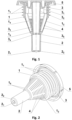
- Fig.1 to Fig.9 depict the first embodiment of the present invention in accordance wherewith the closing filtering device for a bottle containing a liquid comprises a hollow stopper 1, which is fixed in a pouring opening of a bottleneck 6 ( Fig.8 ) by means of sealing protrusions 1 1 .
- the sealing protrusions 1 1 are provided on the external surface of the stopper 1 in the upper part thereof ( Fig.1 ).
- a lower part 1 2 of the stopper 1 is made in the form of the truncated cone ( Fig.2 ) with a central opening 1 3 being formed in the upper, smaller base whereof ( Fig.4 ).
- An air duct tube 2 adjoins to a support band 1 5 and, in its inlet, is in fluid communication with the central opening 1 3 of the stopper 1.
- an end wall 2 2 is provided, in which an outlet opening 2 1 is provided in the form of a confuser ( Fig.1 ) expanding from the central opening 1 3 of the stopper 1.
- the outlet opening of the air duct 3 3 of the pouring insert 3 comprises a cross partition 3 4 with pass-through openings 3 5 .
- the longitudinal ribs 1 4 Disposed in the cavity of the stopper 1 are the longitudinal ribs 1 4 , which adjoin (see Fig.1 , Fig. 4 ) to the support band 1 5 , which is provided in the upper, smaller base of the truncated cone of the lower part 1 2 of the stopper 1.
- Filtering openings 4 are provided on the side surface of the truncated cone of the lower part 1 2 of the stopper 1.
- the filtering openings 4 have a slit-like shape and are located between adjacent longitudinal ribs 1 4 ( Fig.4 ).
- a sealing element of the pouring insert 3 is made in the form of a cover 5, which closes (seals) the pouring openings 3 1 and the inlet opening of the air duct 3 3 of the pouring insert 3.
- the closing filtering device for a bottle containing a liquid in accordance with the first embodiment of this invention is fabricated as follows: First, the stopper 1 with the air duct tube 2; the pouring insert 3 with the air duct 3 3 ; the cover 5, a protective cap 7 are produced in separate casting molds.
- the stopper 1 and the cover 5 are produced, for example, of polyethylene.
- the pouring insert 3 with the air duct 3 3 is made, for example, of polycarbonate.
- the protective cap 7 is fabricated, for example, using a metal drawing method, for example, of aluminum or alloys thereof.
- the protective cap 7 Prior to the assembly, the protective cap 7 is molded, namely, an internal collar 7 1 is molded to retain the closing filtering device assembled in the protective cap 7 due to the engagement thereof with the cover 5, as well as a perforation line 7 2 used to separate a lower part 7 3 of the protective cap 7 is produced.
- the closing filtering device is then assembled.
- the stopper 1 is connected to the pouring insert 3, and, as a result thereof, the pouring insert 3 is fixed on the stopper 1 and the outlet of the air duct 3 3 is inserted into the central opening 1 3 of the stopper 1.
- the external surface of air duct 3 3 adjoins the support band 1 5 , and the internal cavity of the air duct 3 3 is in fluid communication with the internal cavity of the air duct tube 2 of the stopper 1.
- the assembled closing filtering device is ten installed into the protective cap 7; when doing so, the outer edge of the cover 5 engages with the internal collar 7 1 of the protective cap 7 and, as a result thereof, the cover 5 is fixed on the internal end surface of the protective cap 7.
- the closing filtering device for a bottle containing a liquid which device is inserted into the protective cap 7 ( Fig.7 ), is produced.
- the assembled closing filtering device ( Fig.7 ) is then delivered (transported) to a filling line where a solid content is placed into the bottle cavity (not shown in the Figures) and a liquid is poured into the bottle cavity through the pouring opening of the bottleneck 6.
- the closing filtering device is then installed onto the bottleneck 6 and is fixed thereon ( Fig.7 ).
- the stopper 1 is disposed in the pouring openings of the bottleneck 6 and is fixed therein by means of the sealing protrusions 1 1 .
- the pouring insert 3 is fixed on the stopper 1.
- a thread 7 4 is then rolled in the upper part of the protective cap 7, which thread matches a male thread 6 1 of the bottleneck 6 and a fixing groove 7 5 at a lower part 7 3 of the protective cap 7 is rolled.
- the fixing groove 7 5 engages with an external collar 6 2 of the bottleneck 6.
- the assembly for closing a bottle containing a liquid in accordance with the first embodiment of the present invention is characterized by the presence of the bottleneck 6, fixed whereon is the closing filtering device, in which, on the side surface of the truncated cone of the lower part 1 2 of the stopper 1, the filtering openings 4 are provided while in the upper, smaller base of the truncated cone of the lower part 1 2 of the stopper 1, the support band 1 5 is provided all the way around the central opening 1 3 .
- the air duct tube 2 being, in its inlet, in fluid communication with the central opening 1 3 adjoins the support band 1 5 ;
- the pouring insert 3 comprises additionally the air duct 3 3 , which, on its inlet side, adjoins to the pouring insert 3, while the outlet side of the air duct 3 3 in inserted, in a backlash-free manner, into the central opening 3 1 of the stopper 1, which opening being in fluid communication with air duct tube 2 of the stopper 1.
- the sealing element of the pouring insert 3 is made in the form of the cover 5.
- the cover 5 is fixed by means of the internal collar 7 1 on the internal end surface of the protective cap 7.
- the thread 7 4 of the protective cap 7 matches a male thread 6 1 of the bottleneck 6.
- the fixing groove 7 5 is provided in the lower part 7 3 of the protective cap 7 and engages with c the external collar 6 2 of the bottleneck 6 this being necessary to separate the lower part 7 3 of the protective cap 7 along the perforation line 7 2 .
- the bottle containing the liquid with the closing assembly formed on its bottleneck 6 is delivered to the ultimate consumer.
- the ultimate consumer holds the bottle with one hand, while, with the other hand, holds the upper part the protective cap 7 of the assembly for closing and starts rotating it counterclockwise and, as a result of that the protective cap 7 has the thread 7 4 that mates the male thread 6 1 provided on the external surface of the bottleneck 6, the protective cap 7 at the bottleneck 6, is unscrewed this resulting in the separation of the upper part of the protective cap 7 from its lower part 7 3 , which stays on the bottleneck 6 ( Fig.9 ) and evidences the first opening of the assembly for closing a bottle containing a liquid. Also, in the process of unscrewing the protective cap 7, he cover 5 is separated from the pouring insert 3, this resulting in the opening of the pouring openings 3 1 and the inlet opening of the air duct 3 3 .
- the bottle 6 is tilted and the liquid from the bottle cavity enters the bottleneck 6 and starts flowing through the filtering openings 4 of the lower part 1 3 of the stopper 1.
- the filtering openings 4 solid particles are separated from the liquid and, as a result thereof, the filtered liquid enters the cavity of the stopper 1, where the liquid flow to be poured out is formed.
- the liquid is then poured out of the cavity of the stopper 1 through the pouring openings 3 1 of the pouring insert 3.
- outlet opening 2 1 in the end wall 2 2 in the form of a confuser expanding from the central opening 1 3 of the stopper 1 makes it possible to increase a liquid contact area and, accordingly, this resistance reduces the likelihood of a possible leaking of an unfiltered liquid in the cavity of the air duct tube 2 of the stopper 1 through its outlet opening 2 1 .
- the pass-through openings 3 5 of the cross partition 3 4 comprise a smaller cross-sectional area as compared to the outlet opening 2 1 of the air duct tube 2, and this reduces the likelihood of the flowing of an unfiltered liquid in the cavity of the air duct 3 3 .
- Fig.10 depicts the second embodiment of the present invention, which differs from the first embodiment of the present invention in that in the area of the outlet opening of the air duct 3 3 , a cross-sectional narrowing of the air duct tube 3 3 is provided and, as a result whereof, a shoulder 3 6 is formed on its outer surface said shoulder resting on the longitudinal ribs 1 4 in the area where they adjoin to the support band 1 5 of the central opening 1 3 of the stopper 1.
- the presence of the shoulder 3 6 of the air duct 3 3 makes it possible to install the pouring insert 3 with an interference fit this reducing the vibration of the outlet side of the air duct 3 3 .
- the sealing element is configured in the form of a sealing gasket 5 1 secured on the internal end surface of the protective cap 7 by means of the internal collar 7 1 .
- the option of gluing the sealing gasket 5 1 to the internal end surface of the protective cap 7 is also envisaged.
- the sealing gasket 5 1 may be provided on the internal end surface of the protective cap 7 by casting a sealing material, for example, PROVALIN ® brand.
- the closing filtering device in accordance with the second embodiment consists of the following elements: the stopper 1 with the air duct tube 2, the pouring insert 3 with the air duct 3 3 , the sealing gasket 5 1 and the protective cap 7.
- the closing filtering device for a bottle containing a liquid in accordance with this embodiment comprises the stopper 1, the pouring insert 3 with the pouring openings 3 1 , connected to said stopper 1, and the sealing element of said pouring insert 3, configured in the form of the sealing gasket 5 1 .
- the pouring insert 3 comprises additionally the air duct 3 3 , which, on its inlet side, adjoins to the pouring insert 3 while the the outlet side of the air duct 3 3 is inserted, in a backlash-free manner, into the central opening 3 1 of the stopper 1 connected to the air duct tube 2 of the stopper 1.
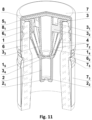
- the third embodiment of the present invention depicted in Fig.11 differs from the second embodiment in that an elastic insert 8 is secured on the end surface of the protective cap 7 with a sealing element configured in the form of the sealing gasket 5 1 being disposed on the end surface of said elastic insert.
- the elastic insert 8 comprises a female thread 8 1 , which engages with the male thread 6 1 provided on the external surface of the bottleneck 6.
- the sealing gasket 5 1 may be secured on the internal end surface of the elastic insert 8 or may be molded by casting a sealing material, for example, PROVALIN ® brand, on the internal end surface of the elastic insert.
- the closing filtering device in accordance with the third embodiment consists of the following elements: the stopper 1 with the air duct tube 2, the pouring insert 3 with the air duct 3 3 , the elastic insert 8, the sealing gasket 5 1 and the protective cap 7.
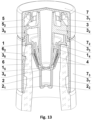
- the fourth embodiment of the present invention depicted in Fig.12 differs from the second embodiment in that a thread 3 9 , which engages with the female thread 5 2 of the cover 5 is provided on the external surface of the pouring insert 3.
- a skirt 3 7 with retainers 3 8 that face inward into the pouring insert 3 and engage with an external collar 6 2 provided on the bottleneck 6.
- the stopper 1 is disposed in the pouring opening of the bottleneck 6 while comprises an external bent provided in the upper part of the stopper 1 and resting onto the external end surface of the pouring opening of the bottleneck 6. Also, in the upper part of the stopper 1 an upper skirt is provided the upper surface whereof adjoins to the internal surface of the pouring insert.
- the closing filtering device in accordance with the fourth embodiment consists of the following elements: the stopper 1 with the air duct tube 2, the pouring insert 3 with the air duct 3 3 , with the thread 3 9 , with the lower skirt 3 7 and with the retainers 3 8 ; the cover 5 with the female thread 5 2 , and the protective cap 7.
- the fifth embodiment of the present invention depicted in Fig.15 differs from the fourth embodiment of the present invention in that the skirt 3 7 of the pouring insert 3 has an elongated shape and is located in the upper part thereof are retainers 3 8 that face inward into the pouring insert 3 and engage with the external collar 6 2 provided on the bottleneck 6.
- the sixth embodiment of the present invention depicted in Fig.14 , Fig.15 differs from the first embodiment in that the pouring insert 3 comprises a cross partition 3 10 , which, through the radial ribs 3 2 , adjoins to the pouring insert 3 with the pouring openings 3 1 being disposed between the radial ribs 3 2 .
- the inventors have found that the use the stopper 1 in accordance with the present invention, due to the fluid communication between the air duct tube 2 and the central opening 1 3 of the support band 1 5 of the stopper 1 located in the upper, smaller base of the truncated cone of the lower part 1 2 of the stopper 1 produces a pressure difference sufficient to carry air from the cavity of the stopper 1 into the bottle cavity through the outlet opening 2 1 of the air duct tube 2.
- the lower part 1 2 of the stopper 1 identification configured in the form of the truncated cone, and, In the process of pouring the liquid out of the bottle, it is tilted, all this leads to an uneven passage of the liquid through the filtering openings 4 and this results in the presence of air in the cavity of the stopper 1, which air enters said cavity through the pouring openings 3 1 of the pouring insert 3.
- the presence of the cross partition 3 10 contributes to the formation of a liquid flow, which is poured out of the pouring openings 3 1 , as well as prevents the liquid from being splashed.
- the assembly for closing a bottle containing a liquid ( Fig.15 ), wherein the sixth embodiment of the present invention is implemented.
- Said assembly for closing a bottle containing comprises the bottleneck 6 of the bottle, on the pouring opening whereof the closing filtering device is secured, which device comprises the stopper 1, the pouring insert 3 ( Fig.14 ) with the pouring openings 3 1 , said pouring insert being connected to said stopper 1, the filtering openings 4 and the sealing element of the pouring insert 3 configured in the form of the cover 5.
- the filtering openings 4 are provided while in the upper, smaller base of the truncated cone of the lower part 1 2 of the stopper 1, the support band 1 5 is provided all the way around the central opening 1 3 of the stopper 1.
- the pouring insert 3 comprises the cross partition 3 10 , which adjoins to the pouring insert 3 through the radial ribs 3 2 .
- the pouring openings 3 1 are disposed between the radial ribs 3 2 .
- the authors carried out a series of experiments to determine the rate of pouring liquid from a bottle when using the present invention.
- a 0.5-L glass bottle with a diameter of the bottleneck pouring openings of 20.5 mm was selected. Pre-crushed solid contents were placed in the bottle cavity, and then liquid - 40% vodka - was poured into the bottle cavity. A liquid with a high concentration of fine solids was artificially formed in the bottle cavity.
- a developed filtering surface is formed, on which the filtering openings are provided, and making them slit-like simplifies the manufacture of the stopper and increases their throughput capacity.
- the location of the filtering openings between the longitudinal ribs increases the reliability of the stopper design.
- truncated cone also refers to cone-like truncated shapes similar to a truncated cone, for example, the presence of kinks on the internal lateral surface of the truncated cone.
- the filter filtering device may be installed onto the bottleneck without the protective cap.
- a protective film (not shown in the figures) is applied to the cover and the bottleneck on the filling line after the closing filtering device has been installed, for example, by means of heat welding. The ultimate consumer tears off this protective film and then removes the cover from the stopper.
- the protective cap or the end surface and/or the side surface of the protective cap may also be embossed.
- the filtering openings may be provided either in parallel or at an angle to the stopper or in various combinations.
- the technical result of the present invention is that the manufacture and service of the closing filtering device, the stopper thereof, and the assembly for closing a bottle containing a liquid are simplified and the reliability thereof is improved.
Landscapes
- Engineering & Computer Science (AREA)
- Mechanical Engineering (AREA)
- Water Supply & Treatment (AREA)
- Chemical & Material Sciences (AREA)
- Chemical Kinetics & Catalysis (AREA)
- Closures For Containers (AREA)
- Filling Of Jars Or Cans And Processes For Cleaning And Sealing Jars (AREA)
Claims (23)
- Bouchon de dispositif de bouchage filtrant pour une bouteille contenant un liquide, lequel est placé dans l'ouverture de versement du col de ladite bouteille contenant le liquide, ledit bouchon comprenant des saillies d'étanchéité (11) disposées sur la surface extérieure dudit bouchon (1) dans la partie supérieure de celui-ci, la partie inférieure (12) du bouchon (1) étant rétrécie en forme de cône tronqué, dans la base plus étroite supérieure duquel se trouve une ouverture centrale (13), ledit bouchon (1) comprenant également des nervures longitudinales (14),
caractérisé en ce que ladite ouverture est reliée à la cavité du bouchon (1) et en ce que des ouvertures filtrantes (4) sont disposées sur la surface latérale du cône tronqué de la partie inférieure (12) du bouchon (1), et, dans la base supérieure plus étroite du cône tronqué de la partie inférieure (12) du bouchon (1), il est prévu une bande de support (15) s'étendant tout autour de l'ouverture centrale (13), avec une tube de conduit d'air (2) adjacent à ladite bande de support (15) et relié à l'ouverture centrale (13) du bouchon (1) au niveau de son entrée. - Bouchon selon la revendication 1, dans lequel une paroi terminale (22) comprenant une ouverture de sortie (21) est disposée sur le côté sortie du tube de conduit d'air (2).
- Bouchon selon la revendication 2, dans lequel l'ouverture de sortie (21) du tube de conduit d'air (2) est configurée sous la forme d'un concentrateur s'élargissant à partir de l'ouverture centrale (13) du bouchon (1).
- Bouchon selon la revendication 1, dans lequel les nervures longitudinales (14) sont adjacentes à la bande de support (15).
- Bouchon selon la revendication 1, dans lequel les ouvertures filtrantes (4) sont conçues comme des fentes et disposées entre des nervures longitudinales (14) adjacentes.
- Dispositif de bouchage filtrant pour une bouteille contenant un liquide, caractérisé en ce que ledit dispositif comprend le bouchon (1) selon l'une quelconque des revendications 1 à 5, un insert verseur (3) avec des ouvertures de versement (31), ledit insert verseur étant relié audit bouchon (1), l'insert verseur (3) comprenant en outre un conduit d'air (33), lequel est adjacent à l'insert verseur (3) sur son côté entrée, tandis que le côté sortie du conduit d'air (33) est inséré sans jeu dans l'ouverture centrale (31) du bouchon (1) en communication fluidique avec le tube de conduit d'air (2) du bouchon (1), ledit dispositif de bouchage filtrant comprenant en outre un élément d'étanchéité de l'insert verseur (3).
- Dispositif selon la revendication 6, dans lequel l'ouverture de sortie du conduit d'air (33) comprend une cloison transversale (34) avec des ouvertures de passage (35).
- Dispositif selon la revendication 6, dans lequel la surface extérieure du conduit d'air (33) de l'insert verseur (3) présente une partie effilée, dont le diamètre diminue à partir de l'insert verseur (3).
- Dispositif selon la revendication 6, dans lequel un élément d'étanchéité de l'insert verseur (3) est configuré sous la forme d'un couvercle (5).
- Dispositif selon la revendication 9, dans lequel ledit dispositif comprend un capuchon de protection (7) à la surface terminale intérieure duquel le couvercle (5) est fixé.
- Dispositif selon la revendication 9, dans lequel, sur la surface extérieure de l'insert verseur (3), il est prévu un filetage (39) s'engageant avec un filetage femelle (52) du couvercle (5).
- Dispositif selon la revendication 6, dans lequel ledit dispositif comprend le capuchon de protection (7) et un élément d'étanchéité de l'insert verseur (3) est configuré sous la forme d'une garniture d'étanchéité (51) fixée à la surface terminale intérieure du capuchon de protection (7).
- Dispositif selon la revendication 6, dans lequel ledit dispositif comprend le capuchon de protection (7), sur la surface terminale duquel est fixé un insert élastique (8), sur la surface terminale intérieure duquel est disposé un élément d'étanchéité configuré sous la forme de la garniture d'étanchéité (51), l'insert élastique (8) comprenant un filetage femelle (81), lequel s'engage avec un filetage mâle (61) disposé sur la surface extérieure du col de bouteille (6).
- Dispositif selon la revendication 6, dans lequel, dans la partie inférieure de l'insert verseur (3), il est prévu une collerette (37) avec des éléments de retenue (38), lesquels sont tournés vers l'intérieur dans l'insert verseur (3) et s'engagent avec un collier externe (62) disposé sur le col de bouteille (6).
- Dispositif selon la revendication 6, dans lequel, dans la zone de l'ouverture de sortie du conduit d'air (33), il est prévu un rétrécissement de section transversale du tube de conduit d'air (33) et, par conséquent, un épaulement (36) est formé sur sa surface extérieure, ledit épaulement reposant sur les nervures longitudinales dans la zone où celles-ci sont adjacentes à la bande de support (15) de l'ouverture centrale (13).
- Dispositif de bouchage filtrant pour une bouteille contenant un liquide, caractérisé en ce que ledit dispositif comprend le bouchon (1) selon l'une quelconque des revendications 1 à 5, l'insert verseur (3) comprenant les ouvertures de versement (31) et étant relié audit bouchon (1), l'insert verseur (3) comprenant en outre une cloison transversale (310) adjacente à l'insert verseur (3) par le biais de nervures radiales (32) avec les ouvertures de versement (31) disposées entre celles-ci, et le dispositif de bouchage filtrant comprend également un élément d'étanchéité de l'insert verseur (3).
- Dispositif selon la revendication 16, dans lequel l'élément d'étanchéité de l'insert verseur (3) est configuré sous la forme du couvercle (5) fixé à l'insert verseur (3).
- Dispositif selon la revendication 17, dans lequel ledit dispositif comprend le capuchon de protection (7), le couvercle (5) étant fixé à la surface terminale intérieure de celui-ci.
- Dispositif selon la revendication 17, dans lequel le filetage (39) est disposé sur la surface extérieure de l'insert verseur (3), ledit filetage d'engageant avec le filetage femelle (52) du couvercle (5).
- Dispositif selon la revendication 16, dans lequel ledit dispositif comprend le capuchon de protection (7), l'élément d'étanchéité est configuré sous la forme de la garniture d'étanchéité (51) fixée à la surface terminale intérieure du capuchon de protection (7).
- Dispositif selon la revendication 16, dans lequel ledit dispositif comprend le capuchon de protection (7), à la surface terminale duquel est fixé un insert élastique (8), à la surface terminale intérieure duquel est disposé un élément d'étanchéité configuré sous la forme de la garniture d'étanchéité (51), l'insert élastique (8) comprenant un filetage femelle (81), lequel s'engage avec un filetage mâle (61) disposé sur la surface extérieure du col de bouteille (6).
- Dispositif selon la revendication 16, dans lequel, dans la partie inférieure de l'insert verseur (3), il est prévu une collerette (37) avec des éléments de retenue (38), lesquels sont tournés vers l'intérieur ans l'insert verseur (3) et s'engagent avec un collier extérieur (62) disposé sur le col de bouteille (6).
- Ensemble de bouchage pour une bouteille contenant un ensemble de liquide, caractérisé par la présence d'un col de bouteille de la bouteille contenant le liquide, le dispositif de bouchage filtrant pour une bouteille contenant un liquide selon l'une quelconque des revendications 6 à 22 étant fixé à celui-ci.
Applications Claiming Priority (1)
| Application Number | Priority Date | Filing Date | Title |
|---|---|---|---|
| PCT/IB2020/051377 WO2021009571A1 (fr) | 2020-02-19 | 2020-02-19 | Dispositif de bouchage filtrant, bouchon pour celui-ci et unité de bouchage de bouteille contenant un liquide |
Publications (4)
| Publication Number | Publication Date |
|---|---|
| EP4108308A1 EP4108308A1 (fr) | 2022-12-28 |
| EP4108308A4 EP4108308A4 (fr) | 2023-11-08 |
| EP4108308C0 EP4108308C0 (fr) | 2025-04-02 |
| EP4108308B1 true EP4108308B1 (fr) | 2025-04-02 |
Family
ID=74210231
Family Applications (1)
| Application Number | Title | Priority Date | Filing Date |
|---|---|---|---|
| EP20841081.1A Active EP4108308B1 (fr) | 2020-02-19 | 2020-02-19 | Dispositif de bouchage filtrant, bouchon pour celui-ci et unité de bouchage de bouteille contenant un liquide |
Country Status (5)
| Country | Link |
|---|---|
| US (1) | US20230113632A1 (fr) |
| EP (1) | EP4108308B1 (fr) |
| PL (1) | PL4108308T3 (fr) |
| UA (1) | UA128343C2 (fr) |
| WO (1) | WO2021009571A1 (fr) |
Families Citing this family (1)
| Publication number | Priority date | Publication date | Assignee | Title |
|---|---|---|---|---|
| FR3105186B1 (fr) * | 2019-12-20 | 2021-11-12 | Abc Transfer | Conteneur etanche comprenant un dispositif permettant un raccordement amovible a une enceinte |
Family Cites Families (21)
| Publication number | Priority date | Publication date | Assignee | Title |
|---|---|---|---|---|
| US98343A (en) | 1869-12-28 | Boy -ge | ||
| US3220555A (en) | 1963-05-01 | 1965-11-30 | Elmer D Silha | Ageing filter for whisky in glass bottles |
| DE1915356A1 (de) * | 1969-03-26 | 1970-10-08 | Reinhard Petrich | Flaschenverschluss mit Sieb zum Zurueckhalten von Korkstuecken oder Absetzrueckstaenden |
| US5417860A (en) * | 1993-08-30 | 1995-05-23 | Filtertek, Inc. | Bottle filter and pouring device |
| US5616242A (en) * | 1995-05-26 | 1997-04-01 | Mandola; Mary D. | Two stage bottle filter for the removal of sediment |
| US5688397A (en) * | 1995-06-05 | 1997-11-18 | Malmborg; Rick | Combination bottle cap and filter |
| US5928512A (en) | 1996-04-03 | 1999-07-27 | Plymouth Products, Inc. | Demountable filter for a bottle or the like |
| US5840185A (en) * | 1996-07-23 | 1998-11-24 | Douglass E. Hughes | Sports bottle filter cartridge |
| US5799836A (en) * | 1997-09-10 | 1998-09-01 | Lee; Huoo-Ke | Vented pouring spout with filter |
| US5899349A (en) * | 1997-10-02 | 1999-05-04 | Beckman Instruments, Inc. | Cap/closure having a venting mechanism for use with centrifuge containers |
| RU2381268C1 (ru) * | 2008-05-29 | 2010-02-10 | Общество С Ограниченной Ответственностью "Евростандарт" | Устройство для обработки и очистки жидкого продукта и его узлы |
| JP5224915B2 (ja) * | 2008-06-03 | 2013-07-03 | 大成化工株式会社 | フィルター付き吐出容器 |
| CN102438716A (zh) | 2009-02-27 | 2012-05-02 | T.A.里谢克 | 具有可更换过滤器的多隔间水净化瓶 |
| US20110198279A1 (en) * | 2010-02-12 | 2011-08-18 | Pure Water Global, Inc. | Beverage bottle filter system |
| AU2011316628A1 (en) * | 2010-10-12 | 2013-05-02 | Nalge Nunc International Corporation | Ventable closure with port |
| RU2456342C9 (ru) * | 2011-04-14 | 2016-04-10 | Павел Дмитриевич Жердев | Устройство с наполнителем для укупоривания бутылки и обработки находящегося в ней жидкого продукта |
| EP2692657B1 (fr) * | 2012-08-03 | 2016-10-05 | N.V. quiding | Dispositif de fermeture de bouteilles et procédé de fermeture d'une bouteille muni d'un tel dispositif. |
| US9724629B2 (en) * | 2013-05-20 | 2017-08-08 | Thermos L.L.C. | Bottle system and method for filtering or treating a beverage |
| WO2015125244A1 (fr) * | 2014-02-20 | 2015-08-27 | 堺ディスプレイプロダクト株式会社 | Couvercle et procédé de piégeage de corps étrangers |
| WO2016189528A1 (fr) * | 2015-05-26 | 2016-12-01 | Jumpn'pour Ltd. | Distributeur de liquide sans direction à versement régulier |
| LT6581B (lt) * | 2017-03-22 | 2019-01-10 | Ab "Mv Group Production" | Filtras su oro pralaida butelio kamštyje |
-
2020
- 2020-02-19 US US17/799,777 patent/US20230113632A1/en not_active Abandoned
- 2020-02-19 UA UAA202202814A patent/UA128343C2/uk unknown
- 2020-02-19 EP EP20841081.1A patent/EP4108308B1/fr active Active
- 2020-02-19 WO PCT/IB2020/051377 patent/WO2021009571A1/fr not_active Ceased
- 2020-02-19 PL PL20841081.1T patent/PL4108308T3/pl unknown
Also Published As
| Publication number | Publication date |
|---|---|
| US20230113632A1 (en) | 2023-04-13 |
| EP4108308C0 (fr) | 2025-04-02 |
| PL4108308T3 (pl) | 2025-11-24 |
| WO2021009571A1 (fr) | 2021-01-21 |
| UA128343C2 (uk) | 2024-06-12 |
| EP4108308A4 (fr) | 2023-11-08 |
| EP4108308A1 (fr) | 2022-12-28 |
Similar Documents
| Publication | Publication Date | Title |
|---|---|---|
| US9486754B2 (en) | Wine and liquor aerator fitment | |
| US20130092713A1 (en) | Container fitment having ellipsoidal opening | |
| US6454137B1 (en) | Flow vented and pressure vented closures | |
| EP4108308B1 (fr) | Dispositif de bouchage filtrant, bouchon pour celui-ci et unité de bouchage de bouteille contenant un liquide | |
| US20100018940A1 (en) | Anti-refillling device for the neck of a container, typically a bottle, and a composite stopper cap including said device | |
| MXPA03009520A (es) | Copa para consumo de bebidas, y su uso para degustar champagne. | |
| US11547235B2 (en) | Beverage dripper assemblies and methods | |
| EP0180411B1 (fr) | Verseur empêchant le réemplissage | |
| CA3007522C (fr) | Extremite de canette avec element d'aeration | |
| JPH0680139A (ja) | 液体貯蔵用タンク | |
| US3915360A (en) | Container with tear-out portion | |
| CN1911747B (zh) | 具有内压释放特性的金属制容器盖 | |
| JPH1081356A (ja) | 液体注出具 | |
| JP2001513446A (ja) | 連続鋳造鋳型のための注入口部 | |
| CN108545308A (zh) | 一种防伪防渗漏的瓶盖结构 | |
| CA2237847A1 (fr) | Procede et dispositif de commande d'ecoulement et recipient adapte | |
| KR910000808B1 (ko) | 팩키지와 일체로 형성된 통기관(通氣管) | |
| JP3705913B2 (ja) | 液体注出容器 | |
| US2057745A (en) | Liquid container | |
| KR102689612B1 (ko) | 막걸리 용기 | |
| JP2004210354A (ja) | 容器 | |
| EP3873823B1 (fr) | Bec-verseur pour récipient, en particulier pour une bouteille | |
| KR20120015251A (ko) | 막걸리 병마개 | |
| US20070125783A1 (en) | Scallop cap closures | |
| KR102423879B1 (ko) | 공기유입용 체크밸브가 구비된 액체 용기 뚜껑 |
Legal Events
| Date | Code | Title | Description |
|---|---|---|---|
| STAA | Information on the status of an ep patent application or granted ep patent |
Free format text: STATUS: THE INTERNATIONAL PUBLICATION HAS BEEN MADE |
|
| PUAI | Public reference made under article 153(3) epc to a published international application that has entered the european phase |
Free format text: ORIGINAL CODE: 0009012 |
|
| STAA | Information on the status of an ep patent application or granted ep patent |
Free format text: STATUS: REQUEST FOR EXAMINATION WAS MADE |
|
| 17P | Request for examination filed |
Effective date: 20220913 |
|
| AK | Designated contracting states |
Kind code of ref document: A1 Designated state(s): AL AT BE BG CH CY CZ DE DK EE ES FI FR GB GR HR HU IE IS IT LI LT LU LV MC MK MT NL NO PL PT RO RS SE SI SK SM TR |
|
| DAV | Request for validation of the european patent (deleted) | ||
| DAX | Request for extension of the european patent (deleted) | ||
| REG | Reference to a national code |
Ref country code: DE Ref legal event code: R079 Free format text: PREVIOUS MAIN CLASS: B01D0035020000 Ipc: B65D0047060000 Ref country code: DE Ref legal event code: R079 Ref document number: 602020048852 Country of ref document: DE Free format text: PREVIOUS MAIN CLASS: B01D0035020000 Ipc: B65D0047060000 |
|
| A4 | Supplementary search report drawn up and despatched |
Effective date: 20231010 |
|
| RIC1 | Information provided on ipc code assigned before grant |
Ipc: B65D 41/34 20060101ALI20231004BHEP Ipc: B01D 35/02 20060101ALI20231004BHEP Ipc: B65D 51/24 20060101ALI20231004BHEP Ipc: B65D 47/12 20060101ALI20231004BHEP Ipc: B65D 47/06 20060101AFI20231004BHEP |
|
| REG | Reference to a national code |
Ref country code: DE Ref legal event code: R079 Free format text: PREVIOUS MAIN CLASS: B65D0047060000 Ipc: B65D0041340000 Ref document number: 602020048852 Country of ref document: DE |
|
| GRAP | Despatch of communication of intention to grant a patent |
Free format text: ORIGINAL CODE: EPIDOSNIGR1 |
|
| STAA | Information on the status of an ep patent application or granted ep patent |
Free format text: STATUS: GRANT OF PATENT IS INTENDED |
|
| RIC1 | Information provided on ipc code assigned before grant |
Ipc: B65D 47/04 20060101ALI20241011BHEP Ipc: B65D 51/24 20060101ALI20241011BHEP Ipc: B65D 47/12 20060101ALI20241011BHEP Ipc: B65D 47/06 20060101ALI20241011BHEP Ipc: B65D 41/34 20060101AFI20241011BHEP |
|
| INTG | Intention to grant announced |
Effective date: 20241108 |
|
| GRAS | Grant fee paid |
Free format text: ORIGINAL CODE: EPIDOSNIGR3 |
|
| GRAA | (expected) grant |
Free format text: ORIGINAL CODE: 0009210 |
|
| STAA | Information on the status of an ep patent application or granted ep patent |
Free format text: STATUS: THE PATENT HAS BEEN GRANTED |
|
| AK | Designated contracting states |
Kind code of ref document: B1 Designated state(s): AL AT BE BG CH CY CZ DE DK EE ES FI FR GB GR HR HU IE IS IT LI LT LU LV MC MK MT NL NO PL PT RO RS SE SI SK SM TR |
|
| REG | Reference to a national code |
Ref country code: GB Ref legal event code: FG4D |
|
| REG | Reference to a national code |
Ref country code: CH Ref legal event code: EP |
|
| REG | Reference to a national code |
Ref country code: DE Ref legal event code: R096 Ref document number: 602020048852 Country of ref document: DE |
|
| REG | Reference to a national code |
Ref country code: IE Ref legal event code: FG4D |
|
| U01 | Request for unitary effect filed |
Effective date: 20250424 |
|
| U07 | Unitary effect registered |
Designated state(s): AT BE BG DE DK EE FI FR IT LT LU LV MT NL PT RO SE SI Effective date: 20250502 |
|
| PG25 | Lapsed in a contracting state [announced via postgrant information from national office to epo] |
Ref country code: ES Free format text: LAPSE BECAUSE OF FAILURE TO SUBMIT A TRANSLATION OF THE DESCRIPTION OR TO PAY THE FEE WITHIN THE PRESCRIBED TIME-LIMIT Effective date: 20250402 |
|
| PG25 | Lapsed in a contracting state [announced via postgrant information from national office to epo] |
Ref country code: GR Free format text: LAPSE BECAUSE OF FAILURE TO SUBMIT A TRANSLATION OF THE DESCRIPTION OR TO PAY THE FEE WITHIN THE PRESCRIBED TIME-LIMIT Effective date: 20250703 Ref country code: NO Free format text: LAPSE BECAUSE OF FAILURE TO SUBMIT A TRANSLATION OF THE DESCRIPTION OR TO PAY THE FEE WITHIN THE PRESCRIBED TIME-LIMIT Effective date: 20250702 |
|
| PG25 | Lapsed in a contracting state [announced via postgrant information from national office to epo] |
Ref country code: HR Free format text: LAPSE BECAUSE OF FAILURE TO SUBMIT A TRANSLATION OF THE DESCRIPTION OR TO PAY THE FEE WITHIN THE PRESCRIBED TIME-LIMIT Effective date: 20250402 |
|
| PG25 | Lapsed in a contracting state [announced via postgrant information from national office to epo] |
Ref country code: RS Free format text: LAPSE BECAUSE OF FAILURE TO SUBMIT A TRANSLATION OF THE DESCRIPTION OR TO PAY THE FEE WITHIN THE PRESCRIBED TIME-LIMIT Effective date: 20250702 |
|
| PG25 | Lapsed in a contracting state [announced via postgrant information from national office to epo] |
Ref country code: IS Free format text: LAPSE BECAUSE OF FAILURE TO SUBMIT A TRANSLATION OF THE DESCRIPTION OR TO PAY THE FEE WITHIN THE PRESCRIBED TIME-LIMIT Effective date: 20250802 |
|
| PG25 | Lapsed in a contracting state [announced via postgrant information from national office to epo] |
Ref country code: SM Free format text: LAPSE BECAUSE OF FAILURE TO SUBMIT A TRANSLATION OF THE DESCRIPTION OR TO PAY THE FEE WITHIN THE PRESCRIBED TIME-LIMIT Effective date: 20250402 |
|
| PG25 | Lapsed in a contracting state [announced via postgrant information from national office to epo] |
Ref country code: CZ Free format text: LAPSE BECAUSE OF FAILURE TO SUBMIT A TRANSLATION OF THE DESCRIPTION OR TO PAY THE FEE WITHIN THE PRESCRIBED TIME-LIMIT Effective date: 20250402 |
|
| PGFP | Annual fee paid to national office [announced via postgrant information from national office to epo] |
Ref country code: PL Payment date: 20250521 Year of fee payment: 7 |
|
| PG25 | Lapsed in a contracting state [announced via postgrant information from national office to epo] |
Ref country code: SK Free format text: LAPSE BECAUSE OF FAILURE TO SUBMIT A TRANSLATION OF THE DESCRIPTION OR TO PAY THE FEE WITHIN THE PRESCRIBED TIME-LIMIT Effective date: 20250402 |
|
| PLBE | No opposition filed within time limit |
Free format text: ORIGINAL CODE: 0009261 |
|
| STAA | Information on the status of an ep patent application or granted ep patent |
Free format text: STATUS: NO OPPOSITION FILED WITHIN TIME LIMIT |
|
| REG | Reference to a national code |
Ref country code: CH Ref legal event code: L10 Free format text: ST27 STATUS EVENT CODE: U-0-0-L10-L00 (AS PROVIDED BY THE NATIONAL OFFICE) Effective date: 20260211 |
|
| 26N | No opposition filed |
Effective date: 20260105 |
|
| U20 | Renewal fee for the european patent with unitary effect paid |
Year of fee payment: 7 Effective date: 20260226 |