EP4108358A1 - Appareil, machine et procédé pour déformer les extrémités opposées d'une pièce de fil - Google Patents
Appareil, machine et procédé pour déformer les extrémités opposées d'une pièce de fil Download PDFInfo
- Publication number
- EP4108358A1 EP4108358A1 EP22180631.8A EP22180631A EP4108358A1 EP 4108358 A1 EP4108358 A1 EP 4108358A1 EP 22180631 A EP22180631 A EP 22180631A EP 4108358 A1 EP4108358 A1 EP 4108358A1
- Authority
- EP
- European Patent Office
- Prior art keywords
- piece
- die
- forming
- wire
- mould
- Prior art date
- Legal status (The legal status is an assumption and is not a legal conclusion. Google has not performed a legal analysis and makes no representation as to the accuracy of the status listed.)
- Granted
Links
Images



Classifications
-
- B—PERFORMING OPERATIONS; TRANSPORTING
- B21—MECHANICAL METAL-WORKING WITHOUT ESSENTIALLY REMOVING MATERIAL; PUNCHING METAL
- B21F—WORKING OR PROCESSING OF METAL WIRE
- B21F5/00—Upsetting wire
- B21F5/005—Upsetting wire
-
- B—PERFORMING OPERATIONS; TRANSPORTING
- B21—MECHANICAL METAL-WORKING WITHOUT ESSENTIALLY REMOVING MATERIAL; PUNCHING METAL
- B21J—FORGING; HAMMERING; PRESSING METAL; RIVETING; FORGE FURNACES
- B21J5/00—Methods for forging, hammering, or pressing; Special equipment or accessories therefor
- B21J5/06—Methods for forging, hammering, or pressing; Special equipment or accessories therefor for performing particular operations
- B21J5/08—Upsetting
-
- B—PERFORMING OPERATIONS; TRANSPORTING
- B21—MECHANICAL METAL-WORKING WITHOUT ESSENTIALLY REMOVING MATERIAL; PUNCHING METAL
- B21J—FORGING; HAMMERING; PRESSING METAL; RIVETING; FORGE FURNACES
- B21J9/00—Forging presses
- B21J9/02—Special design or construction
- B21J9/022—Special design or construction multi-stage forging presses
-
- B—PERFORMING OPERATIONS; TRANSPORTING
- B21—MECHANICAL METAL-WORKING WITHOUT ESSENTIALLY REMOVING MATERIAL; PUNCHING METAL
- B21K—MAKING FORGED OR PRESSED METAL PRODUCTS, e.g. HORSE-SHOES, RIVETS, BOLTS OR WHEELS
- B21K5/00—Making tools or tool parts, e.g. pliers
- B21K5/16—Making tools or tool parts, e.g. pliers tools for turning nuts
Definitions
- the present invention relates to:
- an example of such a need consists in spanners with a shaped double end having a specific form, for example a hexagonal or male star-like form, used to operate corresponding parts with a female hexagonal form (socket-head screw) or star-like form and the like.
- forming/bending machines designed to machine sections of wire having a predefined length so as to deform the opposite ends thereof; said machines however have a number of drawbacks including the fact that it is not possible to shape both ends since double deformation with upsetting and enlargement of the two ends would result in the formation of undercuts which would prevent the extraction of the machined piece.
- the known machines therefore envisage the formation of a first end with a diameter greater than that of the initial wire by means of a first cold-moulding upsetting operation so as to obtain the necessary increased diameter and a subsequent extrusion operation in order to obtain the final desired (for example hexagonal) form; and the formation of the second end with a diameter smaller than that of the wire by means of a corresponding extrusion operation which also defines the final form of the spanner.
- Machines of this type are for example known from EP 1 018 406 B1 in the name of the same present Applicant.
- the technical problem which is posed, therefore, is to provide an apparatus which is able to machine portions of wire-shaped material in order to obtain operating spanners having both ends shaped, for example in the manner of hexagons or the like, with a cross-sectional area greater than that of the initial wire, achieving a significant reduction in the amount of initial material required and at the same time resulting in spanners which have a high mechanical resistance in particular to bending.
- this apparatus should have small dimensions, be easy and inexpensive to produce and assemble and be able to be easily installed at any user location using normal standardized connection means.
- the invention therefore relates to an apparatus for deforming opposite first and second ends of a piece of wire extending in a longitudinal direction, comprising a first device for forming the first end of the piece of wire, configured to form the first end by means of cold-deformation, such as to produce a cross-section of the first end greater than the cross-section of the initial piece of wire; and a second device for forming the second end of the same piece of wire, configured to form the second end by means of cold-deformation such as to produce a cross-section of the formed second end greater than the cross-section of the initial piece of wire.
- the apparatus is therefore able to form the two ends with the desired final form employing only two forming steps/devices, being moreover compact and simpler and resulting in less wastage of material.
- said first device for forming the first end and second device for forming the opposite end may be arranged alongside each other in a transverse direction perpendicular to the longitudinal direction.
- the first device for forming the first end and the second device for forming the second end each comprise a fixed die assembly and a finishing assembly which is coaxially movable in the longitudinal direction from/towards the associated die assembly from a distanced position into a position in contact with the latter.
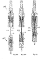
- the first end is deformed inside the first movable finishing assembly with the finishing assembly in the position in contact with the first die assembly and the second end is deformed inside the second fixed die assembly with the first end housed inside the second movable finishing assembly which is in the position where it is in contact with the second die assembly.
- the two opposite ends may be formed by moving only the two finishing assemblies and preferably without having to adjust the orientation of the piece of wire.
- the second finishing assembly comprises a housing mould for housing the already formed first end of the piece of wire and a clamp arranged in front of the housing mould, the clamp being operable to close/open so as to grip the body of the piece of wire.
- the second die assembly comprises in turn a mould for forming the second end of the piece of wire and a die clamp, axially arranged between an inlet for the piece of wire and the die mould, which can be operated so as to close around the piece of wire.
- the clamp of the second finisher and the die clamp are preferably in contact with each other, with the clamp of the second finisher partially inserted inside the second die assembly.
- the piece of wire is firmly retained and correctly positioned during forming of the second end, reducing further the risk of deformations and improving the machining precision and therefore the quality of the finished product.
- the present invention relates furthermore to a forming machine according to Claim 19 and a forming method according to Claim 21.
- the step for forming the first end comprises:
- the step for forming the second end comprises:
- the step for forming the second end may comprise:
- the cold-deformation may be in particular an upsetting operation.
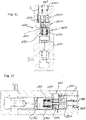
- a longitudinal reference axis X-X corresponding to the greater dimension of the piece of wire 1 whose opposite ends 1a,1b are to be formed, as well as a radial/transverse direction Y-Y perpendicular to the preceding direction, are assumed solely for easier description and without a limiting meaning; below adjectives such as “lower” (or “bottom”) and “upper” (or “top”) and will be used to identify relative positions of components of the assemblies with reference to the vertical orientations shown in the figures; it is understood that these adjectives may be modified for example with reference to a horizontal orientation as shown by way of example in Figs. 11,12 .
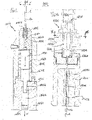
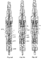
- the apparatus comprises a first device 1000 for forming the first end 1a of a piece of wire 1, and a second device 2000 for forming the second end 1b of the same piece 1 of wire.
- the first device 1000 comprises:
- the first finisher 1100 is movable in the axial/longitudinal direction X-X from a position distanced from the first die 1200, said position allowing the positioning of the piece of wire 1 between the two assemblies where it is arranged coaxially therewith, a position close to the first die 1200 where the subsequent movements for forming the first end 1a of the wire will be performed.
- the first finishing assembly 1100 comprises:
- the ram 1150 may in turn be moved by actuating means conventional per se and only schematically illustrated in Figs. 11 and 12 .
- the piston 1130 is coaxially arranged inside the casing and displaceable in both senses of the longitudinal direction X-X between a positioned distanced from the plug 1160, corresponding to the position where the punch 1112 is extracted from the casing 1101 and a position of bearing contact against the plug 1160, corresponding to the retracted position of the punch.
- the piston 1130 is in particular movable together with the casing so as to push against the punch 1112 during forming and in the opposite sense to the casing so as to allow the punch 1112 to return into the position extracted from the casing, following the return movement of the casing.
- a spring 1140 is arranged between the mould 1110 and a shoulder 1102, inside the casing and axially opposite the mould, said spring, as will become clearer below, being designed to be compressed by a movement of the casing with respect to the mould 1111 towards the first die, when the mould is stably resting against the die 1200 during the forming step.
- the ram 1150 is crossed by a through-duct 1150a which is designed to allow the coaxial insertion of a pusher 1131, movable in the longitudinal direction X-X with respect to the ram 1150 so as to act on the rod 1130a of the piston 1130 and displace it coaxially with respect to the casing 1101.
- the plug 1160 of the casing 1101 has a through-hole such as to allow the insertion of the rod 1130a, but not the passage of the piston 1130; with this configuration, when the casing is displaced towards the first die of the ram 1150, the piston 1130 comes into bearing contact with the plug 1160 and becomes displaceably integral with the casing 1101 for the forming of the first end.
- the pusher 1132 acts against the rod 1130a of the piston, causing the relative movement thereof with respect to the casing, as far as the position distanced from the plug 1160, corresponding to the position where the punch 1112 is extracted from the casing 1101.
- an example of the first auxiliary assembly or first fixed die 1200 comprises:
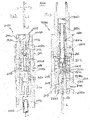
- a preferred example of a second forming device 2000 designed to form the second end 1b of the piece of wire 1 comprises:
- the second finisher 2100 is movable from a first position coaxially spaced from the second die 2200 and designed to allow the positioning, in the transverse direction, of the piece of wire 1 between the two assemblies, into a position coaxially in contact with the second die, where insertion of the second end 1b of the piece inside the second die 2000 and the movements for forming the second end 1b of the piece 1 inside the second die 2000 will be performed.
- the second finisher 2100 comprises a sleeve 2101, extending coaxially between a free end directed towards the second die and a rear end which is rigidly connected to a plug 2160 for connection to the ram 2150 for performing displacement.
- the sleeve 2101 has, coaxially arranged inside it, a mould 2111 inserted along the longitudinal axis X-X, a bottom part 2111b of which (distal from the second die) has a circular profile corresponding to the cross-section of a coaxial punch spindle 2120 and the free end 2111a of which (proximal to the second die) is shaped with the form - for example hexagonal form - of the first already formed end 1a which must be inserted inside the mould during forming of the second end 1b of the wire.
- a clamp 2112 is coaxially arranged at the top of the mould 2110 and is inserted inside the free end (top end in the example shown) of the sleeve 2101, the jaws thereof being able to be operated so as to open/close in the radial/transverse direction Y-Y so as to clamp the cylindrical body of the piece of wire 1.
- the opening/closing of the clamp 2112 is controlled by means of a coaxial counter-wedge 2113, a free end of which (directed towards the second die) contains and operates said jaws and an opposite (rear) end of which is displaceably integral with the plug 2160 and therefore with the actuating ram 2150 and the sleeve 2101.
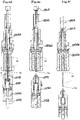
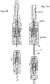
- the clamp 2112 is of the type with four segments 2112a ( Figs. 8a, 8b ) in the form of an overturned truncated cone with an inclined outer side; the segments are closed ( Fig. 8a ) in the radial direction by the counter-wedge 2113.
- the counter-wedge 2113 moves axially towards the second die 2200 together with the clamp 2112, pushed by the ram 2150; when the counter-wedge 2113 reaches and bears against the second die, the clamp 2112 is forced to move coaxially with respect to the counter-wedge 2113 against the action of springs 2115, causing the closing of the segments which form the jaws 2112a; the reverse opening movement ( Fig. 8b ) of the segments is instead produced by the action of the springs 2115 which, compressed during clamping, return into the initial position following retraction of the ram and therefore the counter-wedge with respect to the open position of the jaws 2112a.
- a longitudinal spindle 2120 which is coaxially inserted inside the sleeve 2101 through the clamp 2112 and the mould 2111, is movable axially with respect to the mould 2111 between a forming position, in which it is designed to form a longitudinal positioning stop for the first end 1a of the wire inside the second finisher, in particular inside the free end 2111a of the mould 2111 designed to receive the already formed first end 1a of the piece of wire 1, and an extraction position, in which it projects from the mould 2111.
- a plunger 2131 coaxial with the spindle 2120 is arranged below the latter, having one end 2131a placed in contact with the spindle 2120.
- the other end 2131b of the plunger is situated opposite a coaxial piston 2130, which can be operated in both senses of the longitudinal direction X-X, between a forming position where it is fixed with respect to the sleeve 2101, in particular bearing against the plunger 2160 and therefore rigidly connected to the ram 2150, so as to push against the plunger 2131 and therefore the spindle 2120 when the finisher moves towards the die during the forming step, and an extraction position, in which it is displaced towards the second die with respect to the sleeve 2101 and the ram 2150, so as to allow the return movement of the spindle 2120 into the extraction position for extraction of the piece 1 once forming has been completed.
- the return movement of the piston 2130 may be produced by the movement of the sleeve 2201 away from the die 220, in cooperation with a pusher 2132 which is inserted coaxially inside a through-duct which passes through the ram 2150 so as to act on the piston 2130 and displace it coaxially with respect to the sleeve 2101 and the ram 2150.
- the second assembly or second, fixed, die 2200 for forming the second end 1b of the wire 1 comprises:
- the second die assembly further comprises: an upper spacer 2203, which is axially constrained to the base of the machine and inside which a coaxial duct 2204 is formed, inside said duct there being axially slidable a pusher 2205 movable in the longitudinal direction X-X upon operation of an extractor 2204b in turn moved by external synchronized actuating mechanisms (not shown), from a position extracted at the top (not shown in the figures) into a position ( Fig. 4 ) axially inserted as far an end-of-travel position determined by the rod 2204b by means of mechanisms of the machine (not shown).
- the pusher 2205 is coaxially prolonged towards the second finisher by the pin 2205a inserted and slidable inside the duct 2201a, as will become clear below, the extracted position of the pin allowing the coaxial insertion of the piece 1 inside the die and acting as a reaction stop for the forming of the second end 1b of the piece, while the inserted end-of-travel position allows the piece 1 to be pushed out of the die by way of completion of the step for forming the second end.
- the pusher 2205 has a cross-section with hollow lobes 2205a inside which axial pins 2206 are axially inserted, said pins being arranged at a uniform axial distance and being designed to keep the punch centred so as to avoid deformations due to the peak load applied during the forming of the end, the pusher therefore has the same configuration shown in Fig. 7 .
- the apparatus and the machine according to the invention are suitable for the production, with a small number of forming steps, of tools from a piece of wire, the two opposite ends of which have a cross-sectional area greater than the cross-sectional area of the initial wire, said area being able to be kept at a minimum value in relation to the forces, in particular flexing and/or twisting forces, which the finished tool must withstand during use.
Landscapes
- Engineering & Computer Science (AREA)
- Mechanical Engineering (AREA)
- Forging (AREA)
Applications Claiming Priority (1)
| Application Number | Priority Date | Filing Date | Title |
|---|---|---|---|
| IT202100016778 | 2021-06-25 |
Publications (2)
| Publication Number | Publication Date |
|---|---|
| EP4108358A1 true EP4108358A1 (fr) | 2022-12-28 |
| EP4108358B1 EP4108358B1 (fr) | 2024-04-10 |
Family
ID=77802064
Family Applications (1)
| Application Number | Title | Priority Date | Filing Date |
|---|---|---|---|
| EP22180631.8A Active EP4108358B1 (fr) | 2021-06-25 | 2022-06-23 | Appareil, machine et procédé pour déformer les extrémités opposées d'une pièce de fil |
Country Status (1)
| Country | Link |
|---|---|
| EP (1) | EP4108358B1 (fr) |
Citations (5)
| Publication number | Priority date | Publication date | Assignee | Title |
|---|---|---|---|---|
| EP1057553A2 (fr) * | 1999-05-31 | 2000-12-06 | HILTI Aktiengesellschaft | Procédé de fabrication d'un élément de fixation |
| EP1018406B1 (fr) | 1999-11-02 | 2006-04-26 | F.lli Mauri S.r.l. | Procédé de fabrication d'une clé mâle multiple avec différentes dimensions pour serrer des vis, écrous ou semblables |
| US20100300173A1 (en) * | 2009-05-28 | 2010-12-02 | Wafios Aktiengesellschaft | Heading device |
| CN110666075A (zh) * | 2019-11-18 | 2020-01-10 | 黎东 | 螺丝冷镦加工成型装置 |
| WO2020212813A1 (fr) * | 2019-04-18 | 2020-10-22 | F.Lli Mauri S.R.L. | Machine pour l'usinage à froid d'un matériau filiforme et procédé d'usinage de fils au moyen de ladite machine |
-
2022
- 2022-06-23 EP EP22180631.8A patent/EP4108358B1/fr active Active
Patent Citations (5)
| Publication number | Priority date | Publication date | Assignee | Title |
|---|---|---|---|---|
| EP1057553A2 (fr) * | 1999-05-31 | 2000-12-06 | HILTI Aktiengesellschaft | Procédé de fabrication d'un élément de fixation |
| EP1018406B1 (fr) | 1999-11-02 | 2006-04-26 | F.lli Mauri S.r.l. | Procédé de fabrication d'une clé mâle multiple avec différentes dimensions pour serrer des vis, écrous ou semblables |
| US20100300173A1 (en) * | 2009-05-28 | 2010-12-02 | Wafios Aktiengesellschaft | Heading device |
| WO2020212813A1 (fr) * | 2019-04-18 | 2020-10-22 | F.Lli Mauri S.R.L. | Machine pour l'usinage à froid d'un matériau filiforme et procédé d'usinage de fils au moyen de ladite machine |
| CN110666075A (zh) * | 2019-11-18 | 2020-01-10 | 黎东 | 螺丝冷镦加工成型装置 |
Also Published As
| Publication number | Publication date |
|---|---|
| EP4108358B1 (fr) | 2024-04-10 |
Similar Documents
| Publication | Publication Date | Title |
|---|---|---|
| EP1831942B1 (fr) | Procede et appareil pour la fabrication d'une borne pour un accumulateur au plomb | |
| KR101989078B1 (ko) | 렌치볼트 제조방법 | |
| JP5688593B2 (ja) | 螺旋状溝付き金属製細長部材におけるツイストドリルまたはスクリューの製造方法および製造装置 | |
| CA2714856C (fr) | Procedes de faconnage par points | |
| CN102170981A (zh) | 用于在空心金属工件上非切削制作外螺纹的方法和装置 | |
| EP3956083B1 (fr) | Machine pour l'usinage à froid d'un matériau filiforme et procédé d'usinage de fils au moyen de ladite machine | |
| EP4108358B1 (fr) | Appareil, machine et procédé pour déformer les extrémités opposées d'une pièce de fil | |
| US3540255A (en) | Method and apparatus for making hollow metal articles | |
| CN118180266A (zh) | 一种精密元件的防变形连续冲压设备 | |
| US3547334A (en) | Apparatus for making cold bonded electrical composite contacts | |
| US3068929A (en) | Tube pointer | |
| US3247533A (en) | Method and apparatus for forming headed blanks | |
| EP4360774B1 (fr) | Procédé de refoulement de tête de barre d'acier et machine associée de refoulement de barre d'acier | |
| US4698902A (en) | Method of making commutator rings | |
| US3349596A (en) | Method and apparatus for making pinion wire and the like | |
| EP0623408B1 (fr) | Appareil et procédé pour la fabrication d'un élément métallique | |
| US6151937A (en) | Machine for forming T-shaped tubular components using a forming material insert | |
| US3587287A (en) | Automatic machine for preparing the ends of metal pipes for the drawing operation | |
| CN117340116A (zh) | 一种铜鼻子冲压成型工艺 | |
| JP3962156B2 (ja) | クリップ成形方法及びクリップ成形装置 | |
| JPH0252140A (ja) | 歯車の鍛造成形装置 | |
| PL225397B1 (pl) | Urządzenie do jednoczesnego wykrawania otworów i przetłoczenia powierzchni metalowych elementów rurowych | |
| KR100579118B1 (ko) | 오일압력스위치용 몸체 제조방법 | |
| US3737999A (en) | Method for making cold bonded electrical composite contacts | |
| EP0533322A1 (fr) | Procédé de fabrication d'objets creux |
Legal Events
| Date | Code | Title | Description |
|---|---|---|---|
| PUAI | Public reference made under article 153(3) epc to a published international application that has entered the european phase |
Free format text: ORIGINAL CODE: 0009012 |
|
| STAA | Information on the status of an ep patent application or granted ep patent |
Free format text: STATUS: THE APPLICATION HAS BEEN PUBLISHED |
|
| AK | Designated contracting states |
Kind code of ref document: A1 Designated state(s): AL AT BE BG CH CY CZ DE DK EE ES FI FR GB GR HR HU IE IS IT LI LT LU LV MC MK MT NL NO PL PT RO RS SE SI SK SM TR |
|
| STAA | Information on the status of an ep patent application or granted ep patent |
Free format text: STATUS: REQUEST FOR EXAMINATION WAS MADE |
|
| 17P | Request for examination filed |
Effective date: 20230612 |
|
| RBV | Designated contracting states (corrected) |
Designated state(s): AL AT BE BG CH CY CZ DE DK EE ES FI FR GB GR HR HU IE IS IT LI LT LU LV MC MK MT NL NO PL PT RO RS SE SI SK SM TR |
|
| GRAP | Despatch of communication of intention to grant a patent |
Free format text: ORIGINAL CODE: EPIDOSNIGR1 |
|
| STAA | Information on the status of an ep patent application or granted ep patent |
Free format text: STATUS: GRANT OF PATENT IS INTENDED |
|
| RIC1 | Information provided on ipc code assigned before grant |
Ipc: B21K 5/16 20060101ALI20231013BHEP Ipc: B21J 9/02 20060101ALI20231013BHEP Ipc: B21J 5/08 20060101ALI20231013BHEP Ipc: B21F 5/00 20060101AFI20231013BHEP |
|
| INTG | Intention to grant announced |
Effective date: 20231116 |
|
| GRAS | Grant fee paid |
Free format text: ORIGINAL CODE: EPIDOSNIGR3 |
|
| GRAA | (expected) grant |
Free format text: ORIGINAL CODE: 0009210 |
|
| STAA | Information on the status of an ep patent application or granted ep patent |
Free format text: STATUS: THE PATENT HAS BEEN GRANTED |
|
| AK | Designated contracting states |
Kind code of ref document: B1 Designated state(s): AL AT BE BG CH CY CZ DE DK EE ES FI FR GB GR HR HU IE IS IT LI LT LU LV MC MK MT NL NO PL PT RO RS SE SI SK SM TR |
|
| REG | Reference to a national code |
Ref country code: GB Ref legal event code: FG4D |
|
| REG | Reference to a national code |
Ref country code: CH Ref legal event code: EP |
|
| P01 | Opt-out of the competence of the unified patent court (upc) registered |
Effective date: 20240311 |
|
| REG | Reference to a national code |
Ref country code: DE Ref legal event code: R096 Ref document number: 602022002786 Country of ref document: DE |
|
| REG | Reference to a national code |
Ref country code: IE Ref legal event code: FG4D |
|
| REG | Reference to a national code |
Ref country code: LT Ref legal event code: MG9D |
|
| REG | Reference to a national code |
Ref country code: NL Ref legal event code: MP Effective date: 20240410 |
|
| REG | Reference to a national code |
Ref country code: AT Ref legal event code: MK05 Ref document number: 1674411 Country of ref document: AT Kind code of ref document: T Effective date: 20240410 |
|
| PG25 | Lapsed in a contracting state [announced via postgrant information from national office to epo] |
Ref country code: NL Free format text: LAPSE BECAUSE OF FAILURE TO SUBMIT A TRANSLATION OF THE DESCRIPTION OR TO PAY THE FEE WITHIN THE PRESCRIBED TIME-LIMIT Effective date: 20240410 |
|
| PG25 | Lapsed in a contracting state [announced via postgrant information from national office to epo] |
Ref country code: NL Free format text: LAPSE BECAUSE OF FAILURE TO SUBMIT A TRANSLATION OF THE DESCRIPTION OR TO PAY THE FEE WITHIN THE PRESCRIBED TIME-LIMIT Effective date: 20240410 |
|
| PG25 | Lapsed in a contracting state [announced via postgrant information from national office to epo] |
Ref country code: IS Free format text: LAPSE BECAUSE OF FAILURE TO SUBMIT A TRANSLATION OF THE DESCRIPTION OR TO PAY THE FEE WITHIN THE PRESCRIBED TIME-LIMIT Effective date: 20240810 |
|
| PG25 | Lapsed in a contracting state [announced via postgrant information from national office to epo] |
Ref country code: BG Free format text: LAPSE BECAUSE OF FAILURE TO SUBMIT A TRANSLATION OF THE DESCRIPTION OR TO PAY THE FEE WITHIN THE PRESCRIBED TIME-LIMIT Effective date: 20240410 |
|
| PG25 | Lapsed in a contracting state [announced via postgrant information from national office to epo] |
Ref country code: FI Free format text: LAPSE BECAUSE OF FAILURE TO SUBMIT A TRANSLATION OF THE DESCRIPTION OR TO PAY THE FEE WITHIN THE PRESCRIBED TIME-LIMIT Effective date: 20240410 Ref country code: HR Free format text: LAPSE BECAUSE OF FAILURE TO SUBMIT A TRANSLATION OF THE DESCRIPTION OR TO PAY THE FEE WITHIN THE PRESCRIBED TIME-LIMIT Effective date: 20240410 |
|
| PG25 | Lapsed in a contracting state [announced via postgrant information from national office to epo] |
Ref country code: GR Free format text: LAPSE BECAUSE OF FAILURE TO SUBMIT A TRANSLATION OF THE DESCRIPTION OR TO PAY THE FEE WITHIN THE PRESCRIBED TIME-LIMIT Effective date: 20240711 |
|
| PG25 | Lapsed in a contracting state [announced via postgrant information from national office to epo] |
Ref country code: PT Free format text: LAPSE BECAUSE OF FAILURE TO SUBMIT A TRANSLATION OF THE DESCRIPTION OR TO PAY THE FEE WITHIN THE PRESCRIBED TIME-LIMIT Effective date: 20240812 |
|
| PG25 | Lapsed in a contracting state [announced via postgrant information from national office to epo] |
Ref country code: ES Free format text: LAPSE BECAUSE OF FAILURE TO SUBMIT A TRANSLATION OF THE DESCRIPTION OR TO PAY THE FEE WITHIN THE PRESCRIBED TIME-LIMIT Effective date: 20240410 |
|
| PG25 | Lapsed in a contracting state [announced via postgrant information from national office to epo] |
Ref country code: AT Free format text: LAPSE BECAUSE OF FAILURE TO SUBMIT A TRANSLATION OF THE DESCRIPTION OR TO PAY THE FEE WITHIN THE PRESCRIBED TIME-LIMIT Effective date: 20240410 |
|
| PG25 | Lapsed in a contracting state [announced via postgrant information from national office to epo] |
Ref country code: PL Free format text: LAPSE BECAUSE OF FAILURE TO SUBMIT A TRANSLATION OF THE DESCRIPTION OR TO PAY THE FEE WITHIN THE PRESCRIBED TIME-LIMIT Effective date: 20240410 |
|
| PG25 | Lapsed in a contracting state [announced via postgrant information from national office to epo] |
Ref country code: LV Free format text: LAPSE BECAUSE OF FAILURE TO SUBMIT A TRANSLATION OF THE DESCRIPTION OR TO PAY THE FEE WITHIN THE PRESCRIBED TIME-LIMIT Effective date: 20240410 |
|
| PG25 | Lapsed in a contracting state [announced via postgrant information from national office to epo] |
Ref country code: PT Free format text: LAPSE BECAUSE OF FAILURE TO SUBMIT A TRANSLATION OF THE DESCRIPTION OR TO PAY THE FEE WITHIN THE PRESCRIBED TIME-LIMIT Effective date: 20240812 Ref country code: PL Free format text: LAPSE BECAUSE OF FAILURE TO SUBMIT A TRANSLATION OF THE DESCRIPTION OR TO PAY THE FEE WITHIN THE PRESCRIBED TIME-LIMIT Effective date: 20240410 Ref country code: NO Free format text: LAPSE BECAUSE OF FAILURE TO SUBMIT A TRANSLATION OF THE DESCRIPTION OR TO PAY THE FEE WITHIN THE PRESCRIBED TIME-LIMIT Effective date: 20240710 Ref country code: LV Free format text: LAPSE BECAUSE OF FAILURE TO SUBMIT A TRANSLATION OF THE DESCRIPTION OR TO PAY THE FEE WITHIN THE PRESCRIBED TIME-LIMIT Effective date: 20240410 Ref country code: IS Free format text: LAPSE BECAUSE OF FAILURE TO SUBMIT A TRANSLATION OF THE DESCRIPTION OR TO PAY THE FEE WITHIN THE PRESCRIBED TIME-LIMIT Effective date: 20240810 Ref country code: HR Free format text: LAPSE BECAUSE OF FAILURE TO SUBMIT A TRANSLATION OF THE DESCRIPTION OR TO PAY THE FEE WITHIN THE PRESCRIBED TIME-LIMIT Effective date: 20240410 Ref country code: GR Free format text: LAPSE BECAUSE OF FAILURE TO SUBMIT A TRANSLATION OF THE DESCRIPTION OR TO PAY THE FEE WITHIN THE PRESCRIBED TIME-LIMIT Effective date: 20240711 Ref country code: FI Free format text: LAPSE BECAUSE OF FAILURE TO SUBMIT A TRANSLATION OF THE DESCRIPTION OR TO PAY THE FEE WITHIN THE PRESCRIBED TIME-LIMIT Effective date: 20240410 Ref country code: ES Free format text: LAPSE BECAUSE OF FAILURE TO SUBMIT A TRANSLATION OF THE DESCRIPTION OR TO PAY THE FEE WITHIN THE PRESCRIBED TIME-LIMIT Effective date: 20240410 Ref country code: BG Free format text: LAPSE BECAUSE OF FAILURE TO SUBMIT A TRANSLATION OF THE DESCRIPTION OR TO PAY THE FEE WITHIN THE PRESCRIBED TIME-LIMIT Effective date: 20240410 Ref country code: AT Free format text: LAPSE BECAUSE OF FAILURE TO SUBMIT A TRANSLATION OF THE DESCRIPTION OR TO PAY THE FEE WITHIN THE PRESCRIBED TIME-LIMIT Effective date: 20240410 Ref country code: RS Free format text: LAPSE BECAUSE OF FAILURE TO SUBMIT A TRANSLATION OF THE DESCRIPTION OR TO PAY THE FEE WITHIN THE PRESCRIBED TIME-LIMIT Effective date: 20240710 |
|
| REG | Reference to a national code |
Ref country code: DE Ref legal event code: R097 Ref document number: 602022002786 Country of ref document: DE |
|
| PG25 | Lapsed in a contracting state [announced via postgrant information from national office to epo] |
Ref country code: DK Free format text: LAPSE BECAUSE OF FAILURE TO SUBMIT A TRANSLATION OF THE DESCRIPTION OR TO PAY THE FEE WITHIN THE PRESCRIBED TIME-LIMIT Effective date: 20240410 |
|
| PG25 | Lapsed in a contracting state [announced via postgrant information from national office to epo] |
Ref country code: EE Free format text: LAPSE BECAUSE OF FAILURE TO SUBMIT A TRANSLATION OF THE DESCRIPTION OR TO PAY THE FEE WITHIN THE PRESCRIBED TIME-LIMIT Effective date: 20240410 |
|
| PG25 | Lapsed in a contracting state [announced via postgrant information from national office to epo] |
Ref country code: CZ Free format text: LAPSE BECAUSE OF FAILURE TO SUBMIT A TRANSLATION OF THE DESCRIPTION OR TO PAY THE FEE WITHIN THE PRESCRIBED TIME-LIMIT Effective date: 20240410 |
|
| PG25 | Lapsed in a contracting state [announced via postgrant information from national office to epo] |
Ref country code: SK Free format text: LAPSE BECAUSE OF FAILURE TO SUBMIT A TRANSLATION OF THE DESCRIPTION OR TO PAY THE FEE WITHIN THE PRESCRIBED TIME-LIMIT Effective date: 20240410 Ref country code: RO Free format text: LAPSE BECAUSE OF FAILURE TO SUBMIT A TRANSLATION OF THE DESCRIPTION OR TO PAY THE FEE WITHIN THE PRESCRIBED TIME-LIMIT Effective date: 20240410 |
|
| PG25 | Lapsed in a contracting state [announced via postgrant information from national office to epo] |
Ref country code: SM Free format text: LAPSE BECAUSE OF FAILURE TO SUBMIT A TRANSLATION OF THE DESCRIPTION OR TO PAY THE FEE WITHIN THE PRESCRIBED TIME-LIMIT Effective date: 20240410 |
|
| PG25 | Lapsed in a contracting state [announced via postgrant information from national office to epo] |
Ref country code: SM Free format text: LAPSE BECAUSE OF FAILURE TO SUBMIT A TRANSLATION OF THE DESCRIPTION OR TO PAY THE FEE WITHIN THE PRESCRIBED TIME-LIMIT Effective date: 20240410 Ref country code: SK Free format text: LAPSE BECAUSE OF FAILURE TO SUBMIT A TRANSLATION OF THE DESCRIPTION OR TO PAY THE FEE WITHIN THE PRESCRIBED TIME-LIMIT Effective date: 20240410 Ref country code: RO Free format text: LAPSE BECAUSE OF FAILURE TO SUBMIT A TRANSLATION OF THE DESCRIPTION OR TO PAY THE FEE WITHIN THE PRESCRIBED TIME-LIMIT Effective date: 20240410 Ref country code: EE Free format text: LAPSE BECAUSE OF FAILURE TO SUBMIT A TRANSLATION OF THE DESCRIPTION OR TO PAY THE FEE WITHIN THE PRESCRIBED TIME-LIMIT Effective date: 20240410 Ref country code: DK Free format text: LAPSE BECAUSE OF FAILURE TO SUBMIT A TRANSLATION OF THE DESCRIPTION OR TO PAY THE FEE WITHIN THE PRESCRIBED TIME-LIMIT Effective date: 20240410 Ref country code: CZ Free format text: LAPSE BECAUSE OF FAILURE TO SUBMIT A TRANSLATION OF THE DESCRIPTION OR TO PAY THE FEE WITHIN THE PRESCRIBED TIME-LIMIT Effective date: 20240410 Ref country code: MC Free format text: LAPSE BECAUSE OF FAILURE TO SUBMIT A TRANSLATION OF THE DESCRIPTION OR TO PAY THE FEE WITHIN THE PRESCRIBED TIME-LIMIT Effective date: 20240410 |
|
| PLBE | No opposition filed within time limit |
Free format text: ORIGINAL CODE: 0009261 |
|
| STAA | Information on the status of an ep patent application or granted ep patent |
Free format text: STATUS: NO OPPOSITION FILED WITHIN TIME LIMIT |
|
| PG25 | Lapsed in a contracting state [announced via postgrant information from national office to epo] |
Ref country code: LU Free format text: LAPSE BECAUSE OF NON-PAYMENT OF DUE FEES Effective date: 20240623 |
|
| 26N | No opposition filed |
Effective date: 20250113 |
|
| PG25 | Lapsed in a contracting state [announced via postgrant information from national office to epo] |
Ref country code: IE Free format text: LAPSE BECAUSE OF NON-PAYMENT OF DUE FEES Effective date: 20240623 |
|
| PG25 | Lapsed in a contracting state [announced via postgrant information from national office to epo] |
Ref country code: SI Free format text: LAPSE BECAUSE OF FAILURE TO SUBMIT A TRANSLATION OF THE DESCRIPTION OR TO PAY THE FEE WITHIN THE PRESCRIBED TIME-LIMIT Effective date: 20240410 Ref country code: BE Free format text: LAPSE BECAUSE OF NON-PAYMENT OF DUE FEES Effective date: 20240630 |
|
| PG25 | Lapsed in a contracting state [announced via postgrant information from national office to epo] |
Ref country code: FR Free format text: LAPSE BECAUSE OF NON-PAYMENT OF DUE FEES Effective date: 20240630 |
|
| REG | Reference to a national code |
Ref country code: BE Ref legal event code: MM Effective date: 20240630 |
|
| PG25 | Lapsed in a contracting state [announced via postgrant information from national office to epo] |
Ref country code: SE Free format text: LAPSE BECAUSE OF FAILURE TO SUBMIT A TRANSLATION OF THE DESCRIPTION OR TO PAY THE FEE WITHIN THE PRESCRIBED TIME-LIMIT Effective date: 20240410 |
|
| PGFP | Annual fee paid to national office [announced via postgrant information from national office to epo] |
Ref country code: DE Payment date: 20250701 Year of fee payment: 4 |
|
| PGFP | Annual fee paid to national office [announced via postgrant information from national office to epo] |
Ref country code: IT Payment date: 20250630 Year of fee payment: 4 |
|
| PG25 | Lapsed in a contracting state [announced via postgrant information from national office to epo] |
Ref country code: CY Free format text: LAPSE BECAUSE OF FAILURE TO SUBMIT A TRANSLATION OF THE DESCRIPTION OR TO PAY THE FEE WITHIN THE PRESCRIBED TIME-LIMIT; INVALID AB INITIO Effective date: 20220623 |
|
| REG | Reference to a national code |
Ref country code: CH Ref legal event code: H13 Free format text: ST27 STATUS EVENT CODE: U-0-0-H10-H13 (AS PROVIDED BY THE NATIONAL OFFICE) Effective date: 20260127 |
|
| PG25 | Lapsed in a contracting state [announced via postgrant information from national office to epo] |
Ref country code: HU Free format text: LAPSE BECAUSE OF FAILURE TO SUBMIT A TRANSLATION OF THE DESCRIPTION OR TO PAY THE FEE WITHIN THE PRESCRIBED TIME-LIMIT; INVALID AB INITIO Effective date: 20220623 |
|
| PG25 | Lapsed in a contracting state [announced via postgrant information from national office to epo] |
Ref country code: CH Free format text: LAPSE BECAUSE OF NON-PAYMENT OF DUE FEES Effective date: 20250630 |