EP4108600A1 - Machine d'emballage dotée d'un convoyeur à barre de poussée - Google Patents
Machine d'emballage dotée d'un convoyeur à barre de poussée Download PDFInfo
- Publication number
- EP4108600A1 EP4108600A1 EP21382564.9A EP21382564A EP4108600A1 EP 4108600 A1 EP4108600 A1 EP 4108600A1 EP 21382564 A EP21382564 A EP 21382564A EP 4108600 A1 EP4108600 A1 EP 4108600A1
- Authority
- EP
- European Patent Office
- Prior art keywords
- push bar
- packaging machine
- coupling device
- machine according
- resilient
- Prior art date
- Legal status (The legal status is an assumption and is not a legal conclusion. Google has not performed a legal analysis and makes no representation as to the accuracy of the status listed.)
- Pending
Links
Images


Classifications
-
- B—PERFORMING OPERATIONS; TRANSPORTING
- B65—CONVEYING; PACKING; STORING; HANDLING THIN OR FILAMENTARY MATERIAL
- B65G—TRANSPORT OR STORAGE DEVICES, e.g. CONVEYORS FOR LOADING OR TIPPING, SHOP CONVEYOR SYSTEMS OR PNEUMATIC TUBE CONVEYORS
- B65G19/00—Conveyors comprising an impeller or a series of impellers carried by an endless traction element and arranged to move articles or materials over a supporting surface or underlying material, e.g. endless scraper conveyors
- B65G19/18—Details
- B65G19/22—Impellers, e.g. push-plates, scrapers; Guiding means therefor
- B65G19/24—Attachment of impellers to traction element
- B65G19/245—Attachment of impellers to traction element for article conveyors, e.g. for container conveyors
-
- B—PERFORMING OPERATIONS; TRANSPORTING
- B65—CONVEYING; PACKING; STORING; HANDLING THIN OR FILAMENTARY MATERIAL
- B65B—MACHINES, APPARATUS OR DEVICES FOR, OR METHODS OF, PACKAGING ARTICLES OR MATERIALS; UNPACKING
- B65B43/00—Forming, feeding, opening or setting-up containers or receptacles in association with packaging
- B65B43/42—Feeding or positioning bags, boxes, or cartons in the distended, opened, or set-up state; Feeding preformed rigid containers, e.g. tins, capsules, glass tubes, glasses, to the packaging position; Locating containers or receptacles at the filling position; Supporting containers or receptacles during the filling operation
- B65B43/52—Feeding or positioning bags, boxes, or cartons in the distended, opened, or set-up state; Feeding preformed rigid containers, e.g. tins, capsules, glass tubes, glasses, to the packaging position; Locating containers or receptacles at the filling position; Supporting containers or receptacles during the filling operation using roller-ways or endless conveyors
-
- B—PERFORMING OPERATIONS; TRANSPORTING
- B65—CONVEYING; PACKING; STORING; HANDLING THIN OR FILAMENTARY MATERIAL
- B65B—MACHINES, APPARATUS OR DEVICES FOR, OR METHODS OF, PACKAGING ARTICLES OR MATERIALS; UNPACKING
- B65B57/00—Automatic control, checking, warning, or safety devices
- B65B57/005—Safety-devices
-
- B—PERFORMING OPERATIONS; TRANSPORTING
- B65—CONVEYING; PACKING; STORING; HANDLING THIN OR FILAMENTARY MATERIAL
- B65G—TRANSPORT OR STORAGE DEVICES, e.g. CONVEYORS FOR LOADING OR TIPPING, SHOP CONVEYOR SYSTEMS OR PNEUMATIC TUBE CONVEYORS
- B65G2207/00—Indexing codes relating to constructional details, configuration and additional features of a handling device, e.g. Conveyors
- B65G2207/40—Safety features of loads, equipment or persons
Definitions
- the present invention refers to a packaging machine according to claim 1.
- EP 3 789 321 A1 discloses a packaging machine that is configured as a tray sealer.
- This tray sealer comprises a push bar conveyor that is configured for transporting product containers from a loading station, where an operator manually fills products into the product containers, towards a downstream positioned sealing station of the tray sealer.
- the push bar conveyor as disclosed in EP 3 789 321 A1 comprises lateral drive chains. In between these lateral drive chains, several push bars are mounted transversely with respect to a conveying direction of the push bar conveyor. The push bars are used to push the filled product containers towards the sealing station, where these containers become closed with a lid foil. The push bars are fixed at their opposite ends with a coupling element at the lateral drive chains. The coupling element is provided as a hollow body that can be pushed onto the ends of the push bar.
- the push bar For coupling the push bar, its ends are positioned in between two mounting pins that protrude inwards from the lateral drive chains. Once both ends of the push bar are positioned in between said mounting pins of the lateral drive chains, at both sides of the push bar the thereat mounted coupling elements are shifted outwards onto the mounting pins of the drive chains. Thereby, the coupling elements are fixed to the mounting pins with frictional forces, such that the push bar has a stable mounting in all directions.
- the above-described mounting of the push bars can be critical with respect to safety requirements at the loading station. Specifically, at the above-described push bar conveyor, a thereat mounted push bar as described above stays secured at the drive chains, even if forces, e.g. effected by an entrapped product container or by an operator's hand, act on the push bar.
- the present invention refers to a packaging machine, preferably a packaging machine that is configured as a tray sealer.
- the inventive packaging machine comprises a loading station where a product container, e.g. a plastic tray or a cardboard tray, is filled with a product.
- a product container e.g. a plastic tray or a cardboard tray
- an operator fills the product container with a product, such as a foodstuff product, like a piece of meat or cheese.
- the loading station comprises a push bar conveyor for transporting the product container along a conveying direction.
- the push bar conveyor comprises at least one pack support plate for supporting a bottom of the product container in a conveying plane, a drive chain, a push bar and a coupling device for mounting the push bar at the drive chain.
- the coupling device comprises a resilient clip for receiving an end of the push bar.
- a resilient clip for receiving an end of the push bar.
- Such resilient clip enables that the end of the push bar can be mounted easily by a clipping action and that the end of the push bar is released from the clip when the push bar receives a force against the clipping action.
- the resilient clip allows the push bar to jump off the clip when an operator's hand, fingers or some kind of object, e.g. a product container, is entrapped between the pack support plate and the push bar while acting with a jamming force onto the push bar that is beyond the clipping action.
- the inventive resilient clip is deformable in such a manner that the thereby clipped end of the push bar can be released in a direction that corresponds to a direction of the jamming force that results from the above mentioned entrapment between the pack support plate and the push bar.
- the inventive resilient clip provides an automatic releasing function which enables the push bar to jump off the coupling device in an emergency.
- the push bar may jump off if a product container jams in between the pack support plate and the push bar, which can prevent the loaded product from being spilled from the product container into an interior of the push bar conveyor. Therefore, machine-cleaning cycles can be reduced, too.
- the inventive coupling device allows an easy and quick mounting of the push bar without using tools.
- the push bar may be mounted at the resilient clip of the coupling device by conducting a clipping action.
- the end of the push bar can be pushed from above into to resilient clip.
- the push bar is mounted to the coupling device by shifting the clip onto the end of the push bar, i.e. in a longitudinal direction of the push bar without thereby conducting a clipping action.
- both ends of the push bar are secured to a coupling device as above and/or in the following.
- each end of the push bar may be clipped into a resilient clip for mounting the push bar in between lateral drive chains of the push bar conveyor.
- both coupling devices that are used for holding the opposite ends of the push bar are identical. Thus, at both sides the same releasing function can be guaranteed.
- both coupling devices that are holding the ends of the push bar act as grippers that may apply parallel holding forces onto the push bar.
- the inventive coupling device is described with respect to one end of the push bar, wherein the technical features of such a coupling device can be identically provided by the other coupling device that is used for holding and mounting the other end of the same push bar at the opposite lateral drive chain.
- the resilient clip holds the end of the push bar with a holding force that is less in an upward direction than in a downward direction, when the push bar is moved along the conveying direction.
- the push bar can jump off the resilient clip in a reliable manner when a jamming force acts from below onto the push bar, wherein the push bar can carry forces from above, such as transport forces that are effected for holding an edge of a product container.
- the clip provides a holding force that is approximately 1.1 to 1.3 times higher than a force of gravity effected by the weight of the push bar. This enables a secure mounting of the push bar when it is moved underneath the transportation plane in an opposite direction with respect to the conveying direction.
- the resilient clip is made of a synthetic material.
- Such clip can be produced as a low cost component.
- the entire coupling device is made of a synthetic material.
- Such coupling device is inexpensive and provides improved haptic properties, such that the operator may conveniently mount it at the end of the push bar, as well as at the lateral drive chains of the push bar conveyor. This results in a more secure mounting of the push bar in a correct manner.
- the coupling device is made of Polyoxymethylene (POM).
- the resilient clip is configured for applying the holding force at the end of the push bar effected by an inherent resistance to deformation of the synthetic material.
- no separate mounting components are necessary for connecting the clip at the end of the push bar.
- the resilient clip is U-shaped. Therefore, the clip provides one open side that allows the end of the push bar to jump off from the clip when a jamming force being produced by a product container or an entrapped hand of the operator is acting on the push bar at least somehow in the direction towards the open side of the clip.
- a U-shaped clip is easy to manufacture and can be handled ergonomically by the operator for mounting the push bar at the coupling device and vice versa in a correct manner.
- the coupling device comprises a cavity for holding the end of the push bar in the conveying direction.
- the cavity can be shaped according to a contour of an outmost section of the end of the push bar.
- the cavity may be formed next to the resilient clip and may be formed with a rigid shape.
- the cavity may have a bottom as vertical support for the end of the push bar.
- the bottom provides a rigid support on which the end of the push bar can be positioned in a stable manner.
- the bottom of the cavity can absorb forces that act from above onto the push bar.
- the cavity may receive the outmost section of the end of the push bar in such a manner that it provides rigidity against forces in the conveying direction but gives little or no resistance to forces that result from an entrapment between the push bar and the pack support plate, i.e. forces with at least some vertically acting force component directed away from the pack support plate.
- the cavity may be a rigid form fitting next to the resilient clip.
- the cavity and the clip are very simple technical means that may synergetically act as co-operating members that allow the push bar to jump off from the coupling device when an entrapment occurs, wherein the cavity additionally gives the push bar a rigid support for precisely positioning and holding the push bar against forces in and opposite to the conveying direction.
- the resilient clip By using the cavity for holding the push bar in the conveying direction, the resilient clip can be formed very flexible for allowing the push bar to easily jump off for safety reasons. Also, thanks to the cavity, the resilient clip can be formed in such a shape that no or at least minimal forces are applied in the conveying direction thereto. In other terms, the cavity unburdens the resilient clip with respect to forces that act in the conveying direction. Thereby, the resilient clip's life span can be increased.
- the cavity is formed with opposing rigid side walls that are distanced from each other with respect to a width of the outmost section of the end of the push bar.
- the outmost section may be received in between these opposing side walls by a form fit.
- the rigid side walls provide inwards facing surfaces towards the outmost section of the end of the push bar. During operation, these surfaces might contact the outmost section of the end of the push bar such that in the conveying direction the push bar is mounted in a predetermined position at the coupling device.
- the cavity comprises a mouth for receiving the end of the push bar, wherein the mouth is facing away from the pack support plate when the push bar is moved in the conveying direction.
- the mouth allows the end of the push bar to jump off the cavity when a force comes from below, e.g. a jamming force that results from a product container or a hand entrapped in between the pack support plate and the push bar.
- the resilient clip comprises a first resilient leg and/or a second resilient leg. These legs can be used for applying the gripping action onto the end of the push bar and enables the same to easily jump off in reaction to a jamming force acting on the push bar, especially when it comes from below.
- first resilient leg and/or the second resilient leg comprises a thickened end portion.
- Said thickened end portion prevents the push bar from jumping off the coupling device in response to a normal movement of the lateral drive chains. It may occur that during operation of the packaging machine, the drive chains might smoothly vibrate, such that the said thickened end portions enable securing the push bar at the coupling device, even if such vibrations occur. Consequently, with respect to normal operating conditions of the packaging machine, i.e. without jamming or entrapped objects, the coupling device safely holds the push bar.
- the thickened end portions can have a form such that forces on the push bar from below resulting from jamming between the pack support plate and the push bar result in that the clip legs spreading in a predetermined manner. Thanks to such spreading action, the push bar can be kicked off when it is released to a point that allows the spread legs contracting towards one another. Thereby, the operator can better recognize that the push bar is no longer securely held at the coupling device.
- the resilient clip comprises at least one notch.
- Such notch can be foreseen in a region of the clip between one of its legs and a bottom of the clip.
- the notch can be formed in order to reach a predetermined holding force that can be performed by the clip.
- a notch is formed between each of the resilient legs and the bottom of the clip.lt is conceivable that the coupling device comprises at least one connector pin for mounting the coupling device at the drive chain.
- the drive chain may comprise a corresponding hollow pin with a receiving hole for accommodating therein the connector pin. Therefore, the coupling device may act as a plug and the drive chain may act as a corresponding socket.
- the coupling device provides two parallel connector pins. This gives the coupling device at least at this side the appearance of a plug connector.
- the coupling device can be secured with a predetermined orientation at the drive chain of the push bar conveyor.
- these two connector pins being coupled at the drive chain, it can be ensured that the resilient clip is held in a predetermined orientation.
- the resilient clip and the connector pins may be formed at opposite sides of the coupling device, such that an operator, at a first instance, recognizes how the coupling device can be used for mounting the push bar thereat, as well as how the coupling device can be mounted at the drive chain in a correct manner.
- the connector pin comprises a deformable head. It is possible that such head comprises at least two hooks that can function as an anchor for mounting the coupling device at the drive chain.
- the coupling device comprises a central solid body, i.e. the coupling device is not formed as a hollow body.
- the operator can hold the coupling device at the central solid body for mounting the coupling device at the drive chain and/or at the end of push bar.
- the aforementioned cavity is formed between the central solid body and the resilient clip.
- the coupling device is an injection molded component, e.g. a POM injection molded component.
- the complete coupling device including the clip and the connector pins, is produced as an integral low cost part that allows mounting the push bar at the drive chain without any other components, such as screws or washers.
- a mounting process for the push bar can be done very quickly and easily.
- the coupling device can be mounted without using tools at the push bar and the drive chain, which prevents the operator from using tools incorrectly. This prevents tools from lying around the push bar conveyor area, especially on the pack support plate, which could be a safety risk during operation of the packaging machine.
- the packaging machine comprises a sensor unit for detecting a mounting state of the push bar.
- the sensor unit may be configured as a visual system, e.g. as a camera that surveilles the operation at the loading station, especially the operation of the push bar conveyor.
- the camera may detect a mounting state of the end of the push bar along its pathway in the conveying direction.
- Such sensor unit can be mounted at a sealing station that is provided downstream of the push bar conveyor.
- the packaging machine comprises a control unit that is connected with the sensor unit.
- the control unit may be configured to continuously receive signals from the sensor unit, wherein in an event of emergency, e.g. by detecting an entrapped hand or a jammed product container, the control unit stops an operation of the entire packaging machine.
- an emergency stop could trigger the control unit to display instructions to the operator on how the packaging machine must be checked and/or get refitted such that a controlled and safe re-start of the packaging machine is possible.
- Fig. 1 shows a packaging machine 1, which is configured as a tray sealer T.
- the packaging machine 1 comprising a loading station 2 where a product container 3 can be filled with a product P.
- the product P can be a foodstuff product.
- an operator who is standing at a lateral side of the loading station 2 manually fills the product P into the container 3.
- there is an increased requirement for safety Specifically, it is important that the operator can be prevented from getting injured, when the operator carelessly takes a hand into an operating area of a push bar conveyor 4.
- the push bar conveyor 4 is configured for transporting the product containers 3 along a conveying direction R. Downstream of the loading station 2, the packaging machine 1 comprises a sealing station 5.
- the sealing station 5 receives the filled product containers 3 from the push bar conveyor 4 and seals the therein received, filled product containers 3 with an upper lid foil 6 that is directed through the sealing station 5.
- a sensor unit 26 is provided for surveilling the loading station 2, especially the operation of the push bar conveyor 4.
- the sealing station 5 is equipped with a control unit 30 with a display 28 for controlling and displaying processes of the packaging machine 1.
- a discharging unit 7 is provided from where the sealed product containers 3 are moved away from the packaging machine 1.
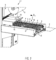
- Fig. 2 shows an enlarged version of the loading station 2.
- the push bar conveyor 4 comprises a pack support plate 8 for supporting a bottom of the product container 3 in a conveying plane E.
- the conveying plane E is formed as a horizontal plane along which the product containers 3 are moved along the loading station 2 in the conveying direction R.
- the push bar conveyor 4 further comprises a drive chain 9, a push bar 10 and a coupling device 11 for mounting the push bar 10 at the drive chain 9.
- Another drive chain which is not shown in Fig. 2 , runs at the other lateral side of the push bar conveyor 4, i.e. opposite to the illustrated drive chain 9.
- Fig. 2 only shows the coupling device 11 for mounting the push bar 10 at the drive chain 9, at the opposite lateral side, another coupling device is used for holding the same push bar 10 against the thereat installed drive chain.
- two coupling devices 11 are used for mounting one push bar 10.
- Fig. 3 shows the coupling device 11 in an isolated manner.
- the coupling device 11 is provided as a safety component that allows the push bar 10 to be released from its mounting state when a jamming force is applied onto the push bar 10, especially a jamming force that acts from a region in between the pack support plate 8 and the push bar 10 onto the same.
- Fig. 3 further shows that the coupling device 11 comprises a resilient clip 12 that is formed for holding an end 13 (see Fig. 5 ) of the push bar 10 in a detachable manner.
- the resilient clip 12 comprises a first resilient leg 14 and a second resilient leg 15.
- the first resilient leg 14 and the second resilient leg 15 protrude from a bottom 16 of the clip 12.
- the first and the second resilient legs 14, 15 are used for clipping in between the end 13 of the push bar 10 for holding the push bar 10 transversely to the conveying direction R.
- the bottom 16 thereby acts as a vertical support for the end 13 of the push bar 10.
- Fig. 3 shows that the coupling device 11 comprises a central solid body 17 and a cavity 22 which is formed between the resilient clip 12 and the central body 17.
- the central solid body 17 has an octagonal shape for easy handling.
- the central solid body 17 provides a first lateral side 18 where the cavity 22 is formed.
- the cavity 22 comprises opposing side walls 22a, 22b that provide a form fit for accurately accommodating there between the end 13 of the push bar 10, especially an outmost section 27 (see Fig. 7 ) thereof.
- the cavity 22 comprises a bottom 22c which acts as a vertical support for the end 13 of the push bar 10. As illustrated in Fig. 3 , the bottom 16 of the clip 12 and the bottom 22c of the cavity 22 together form a flush support surface for the end 13 of the push bar 10.
- Fig. 3 shows connector pins 19 that are provided at a second lateral side 20 of the central solid body 17, wherein the second lateral side 20 is opposite to the first lateral side 18.
- Each of the connector pins 19 comprises a deformable head 21.
- the coupling device 11 can be mounted at the drive chain 9 in thereat provided receiving holes.
- the drive chain 9 is therefore provided as a pin-hole drive chain, wherein the drive chain 9 comprises pins that may connect sections of the chain and which provide the receiving holes for accommodating the connector pins 19.
- Fig. 4 shows a front view of the coupling device 11.
- the cavity 22 provides an upwards opened mouth 23.
- the mouth 23 is facing upwards away from the pack support plate 8 when the coupling device 11 is mounted at the drive chain 9 moving in the conveying direction R.
- the resilient clip 12 comprises lateral notches 24 that are formed between the bottom 16 and each of the first and second resilient legs 14, 15. These notches 24 enable the first and the second legs 14, 15 to be easily forced apart from each other when a jamming force is applied onto the push bar 10 which comes from an entrapped hand or product container 3.
- Fig. 4 shows that the first resilient leg 14 comprises a thickened end portion 25. Such a thickened end portion is also provided on the second resilient leg 15.
- the coupling device 11 as illustrated by Figs. 3 and 4 , is provided as an integral injection-molded component.
- the coupling device 11 looks like a plug, such that a familiar handling thereof can be guaranteed for mounting same at the end 13 of the push bar 10, as well as the drive chain 9.
- Fig. 5 shows the push bar 10 in an isolated manner with coupling devices 11 being mounted at its both ends 13.
- Each of the coupling devices 11 can be pushed onto the end 13 of the push bar 10 or the end 13 of the push bar 10 can be clipped into the resilient clips 12, alternatively, for mounting the push bar 10 at the coupling devices 11.
- Fig. 6 shows an enlarged view of a mounting state of the push bar 10 at the drive chain 9 via the coupling device 11.
- Fig. 6 shows that the end 13 of the push bar 10 has a reduce size in comparison to a rather inward section of the push bar 10. Thereby, the clip 12 can be produced with a reduced size, too.
- Such a reduced end section can be made a standard profile for different push bars 10 for transporting different kinds of product containers 3.
- Fig. 7 shows the push bar 10 with its end 13 mounted at the resilient clip 12 and into the cavity 22 of the coupling device 11 in an isolated manner. Specifically, the outmost section 27 of the end 13 of the push bar 10 is accommodated within the cavity 22 by form fit. Next to the outmost section 27, the end 13 of the push bar 10 is received in the clip 12. Here, it is not necessary to establish a form fit by the clip 12. Rather, the clip 12 may receive the end 13 of the push bar 10 with a very little contact area, e.g. solely in the region of the thickened portions 25.
- Fig. 7 shows several forces in a schematic manner that may act during operation of the push bar conveyor 4. Specifically, Fig. 7 shows in a schematic matter force components of a holding force F for holding the end 13 of the push bar 10 by means of the resilient clip 12 and the cavity 22.
- Fig. 7 shows that the holding force F may act with a vertical force component F1 being directed upwards provided by the resilient clip 12. Such vertical force component F1 allows the push bar 10 to easily jump off the coupling device 11. Also, Fig. 7 shows a transporting force component F2 being directed in the conveying direction R provided by the cavity 22, as well as a support force component F3 that is directed vertically downwards, i.e. opposite to the force component F1, primarily acting onto the bottom 22c of the cavity 22.
- Fig. 7 shows that force component F1 is smaller compared to force component F2, while force component F2 is smaller compared to force component F3, respectively. Therefore, with such a holding force F, the resilient clip 12 opens easier in reaction to a jamming force, i.e. a force that may exist when an operator's hand is jammed between the pack support pate 8 and the push bar 10, than in reaction to other forces that may act in or contrary to the conveying direction R or from above. Consequently, the push bar 10 may jump off the resilient clip 12 without a great resistance, such that a hand form the operator which collides the push bar 10 in an area between the pack support plate 8 and the push bar 10 can be prevented from getting injured.
- a jamming force i.e. a force that may exist when an operator's hand is jammed between the pack support pate 8 and the push bar 10
- the push bar 10 may jump off the resilient clip 12 without a great resistance, such that a hand form the operator which collides the push bar 10 in an area between the pack support plate 8
- Fig. 7 further shows that the transport force component F2, which is bigger than the clipping force component F1, ensures secure transport of the product conveyor 3 in the conveying direction R.
- the force component F3 enables a product container 3 with a heavy product P to dock at the push bar 10 and be pushed securely along the conveying direction R. Due to the rigid shape of the cavity 22, it may provide a big rigidity to big force components F3.
- the coupling device 11 shown by Figs. 3 to 7 is configured as a safety component, such that the push bar 10 may jump off when a finger, hand or some kind of object such as the product container 3 becomes blocked in between the pack support plate 9 and the push bar 10. Due to the shape of the clip 12, the push bar 10 may be easily and quickly mounted thereat without using additional tools.
- the coupling device 11 enables improved machine safety, as a push bar 10 that collides with a die-set of the sealing station 5 may not really counteract as it jumps off from its mounting. Further, the drive chains 9 remain unaffected when the push bar 10 jumps off in reaction to a jamming force, such that the drive chains 9 can be prevented from being stressed.
- the resilient clip 12 gives little resistance to forces thereon resulting from a collision in an area between the transportation plane E and a plane in that the push bar 10 is moving in the conveying direction R, e.g. by a therein jammed product container 3 or an entrapped operator's hand.
Landscapes
- Engineering & Computer Science (AREA)
- Mechanical Engineering (AREA)
- Microelectronics & Electronic Packaging (AREA)
- Supplying Of Containers To The Packaging Station (AREA)
Priority Applications (1)
| Application Number | Priority Date | Filing Date | Title |
|---|---|---|---|
| EP21382564.9A EP4108600A1 (fr) | 2021-06-25 | 2021-06-25 | Machine d'emballage dotée d'un convoyeur à barre de poussée |
Applications Claiming Priority (1)
| Application Number | Priority Date | Filing Date | Title |
|---|---|---|---|
| EP21382564.9A EP4108600A1 (fr) | 2021-06-25 | 2021-06-25 | Machine d'emballage dotée d'un convoyeur à barre de poussée |
Publications (1)
| Publication Number | Publication Date |
|---|---|
| EP4108600A1 true EP4108600A1 (fr) | 2022-12-28 |
Family
ID=76890958
Family Applications (1)
| Application Number | Title | Priority Date | Filing Date |
|---|---|---|---|
| EP21382564.9A Pending EP4108600A1 (fr) | 2021-06-25 | 2021-06-25 | Machine d'emballage dotée d'un convoyeur à barre de poussée |
Country Status (1)
| Country | Link |
|---|---|
| EP (1) | EP4108600A1 (fr) |
Citations (7)
| Publication number | Priority date | Publication date | Assignee | Title |
|---|---|---|---|---|
| US3798732A (en) * | 1971-08-06 | 1974-03-26 | Gea Luftkuehler Happel Gmbh | Apparatus for applying fins to stationarily held pipes without subjecting the fins to vibrations |
| US5562198A (en) * | 1993-11-10 | 1996-10-08 | Joh. Winklhofer & Sohne Gmbh & Co. Kg | Hollow bolt link chain |
| US20050077153A1 (en) * | 2001-08-20 | 2005-04-14 | Achim Krischer | Chain transport system with add-on components |
| US20130227914A1 (en) * | 2012-03-02 | 2013-09-05 | Multivac Sepp Haggenmüller Gmbh & Co. Kg | Tray sealer and method of conveying trays |
| DE202015100657U1 (de) * | 2015-02-11 | 2015-02-23 | Gerhard Schubert Gmbh | Zufuhrketten-Einheit |
| EP3564136A1 (fr) * | 2018-05-02 | 2019-11-06 | MULTIVAC Sepp Haggenmüller SE & Co. KG | Machine d'emballage dotée d'un dispositif de transport |
| EP3789321A1 (fr) | 2019-09-03 | 2021-03-10 | Reepack S.r.l. | Système de fixation de tiges de poussée à une chaîne |
-
2021
- 2021-06-25 EP EP21382564.9A patent/EP4108600A1/fr active Pending
Patent Citations (7)
| Publication number | Priority date | Publication date | Assignee | Title |
|---|---|---|---|---|
| US3798732A (en) * | 1971-08-06 | 1974-03-26 | Gea Luftkuehler Happel Gmbh | Apparatus for applying fins to stationarily held pipes without subjecting the fins to vibrations |
| US5562198A (en) * | 1993-11-10 | 1996-10-08 | Joh. Winklhofer & Sohne Gmbh & Co. Kg | Hollow bolt link chain |
| US20050077153A1 (en) * | 2001-08-20 | 2005-04-14 | Achim Krischer | Chain transport system with add-on components |
| US20130227914A1 (en) * | 2012-03-02 | 2013-09-05 | Multivac Sepp Haggenmüller Gmbh & Co. Kg | Tray sealer and method of conveying trays |
| DE202015100657U1 (de) * | 2015-02-11 | 2015-02-23 | Gerhard Schubert Gmbh | Zufuhrketten-Einheit |
| EP3564136A1 (fr) * | 2018-05-02 | 2019-11-06 | MULTIVAC Sepp Haggenmüller SE & Co. KG | Machine d'emballage dotée d'un dispositif de transport |
| EP3789321A1 (fr) | 2019-09-03 | 2021-03-10 | Reepack S.r.l. | Système de fixation de tiges de poussée à une chaîne |
Similar Documents
| Publication | Publication Date | Title |
|---|---|---|
| US9187252B2 (en) | Transport bag for transporting goods in a hanging manner | |
| EP3070020B1 (fr) | Plateau de transport de bagages | |
| US10954079B2 (en) | Device for loading transport bags | |
| US20140284179A1 (en) | Loading station for transport bags for transporting goods in a hanging manner | |
| US20180186483A1 (en) | Medicine Packaging Apparatus and Medicine Feeding Apparatus | |
| US20190210624A1 (en) | Carriage | |
| JP2016124064A (ja) | ハンド装置および物品移送装置 | |
| EP4108600A1 (fr) | Machine d'emballage dotée d'un convoyeur à barre de poussée | |
| US20180229944A1 (en) | Guard device for transport bags in a loading station of an overhead conveyor system and loading station comprising a guard device of this type | |
| US7021026B2 (en) | Netting chutes for manual and/or automated clipping packaging apparatus | |
| US7191892B2 (en) | Apparatus for transferring products from a first conveying line to a second conveying line, in particular for feeding a boxing machine | |
| US6622851B1 (en) | Conveyor section arrangement in a filling station | |
| CN101356093A (zh) | 用于装填容器的方法和装置 | |
| EP3875923B1 (fr) | Corps de support et dispositif de retenue d'articles | |
| KR20170086262A (ko) | 즉석밥 용기 이송 그리퍼 | |
| KR100951917B1 (ko) | 상해 방지용 식품용기 포장장치 | |
| US12404061B2 (en) | Protective slide for a work machine | |
| US5339948A (en) | Conveyor apparatus with unloader | |
| NL2015019B1 (en) | Gripping device for egg package. | |
| WO2017014795A1 (fr) | Transporteur à vis ayant une fermeture à verrou reliée | |
| KR200436784Y1 (ko) | 계량포장장치 | |
| EP4512754A1 (fr) | Dispositif de préhension, ensemble de transport et procédé de transport d'un récipient | |
| US20240327125A1 (en) | Sorting Terminal and Logistics Sorter | |
| US20100258213A1 (en) | Transfer device | |
| KR20260059258A (ko) | 샌드위치 포장용기 이송시스템 |
Legal Events
| Date | Code | Title | Description |
|---|---|---|---|
| PUAI | Public reference made under article 153(3) epc to a published international application that has entered the european phase |
Free format text: ORIGINAL CODE: 0009012 |
|
| STAA | Information on the status of an ep patent application or granted ep patent |
Free format text: STATUS: THE APPLICATION HAS BEEN PUBLISHED |
|
| AK | Designated contracting states |
Kind code of ref document: A1 Designated state(s): AL AT BE BG CH CY CZ DE DK EE ES FI FR GB GR HR HU IE IS IT LI LT LU LV MC MK MT NL NO PL PT RO RS SE SI SK SM TR |
|
| STAA | Information on the status of an ep patent application or granted ep patent |
Free format text: STATUS: REQUEST FOR EXAMINATION WAS MADE |
|
| 17P | Request for examination filed |
Effective date: 20230621 |
|
| RBV | Designated contracting states (corrected) |
Designated state(s): AL AT BE BG CH CY CZ DE DK EE ES FI FR GB GR HR HU IE IS IT LI LT LU LV MC MK MT NL NO PL PT RO RS SE SI SK SM TR |
|
| P01 | Opt-out of the competence of the unified patent court (upc) registered |
Effective date: 20230801 |
|
| STAA | Information on the status of an ep patent application or granted ep patent |
Free format text: STATUS: EXAMINATION IS IN PROGRESS |
|
| 17Q | First examination report despatched |
Effective date: 20241024 |