EP4108861A1 - Bewegungsmultiplikationsvorrichtung für fenster oder türen - Google Patents
Bewegungsmultiplikationsvorrichtung für fenster oder türen Download PDFInfo
- Publication number
- EP4108861A1 EP4108861A1 EP22180640.9A EP22180640A EP4108861A1 EP 4108861 A1 EP4108861 A1 EP 4108861A1 EP 22180640 A EP22180640 A EP 22180640A EP 4108861 A1 EP4108861 A1 EP 4108861A1
- Authority
- EP
- European Patent Office
- Prior art keywords
- ring path
- slider
- window
- door
- movement
- Prior art date
- Legal status (The legal status is an assumption and is not a legal conclusion. Google has not performed a legal analysis and makes no representation as to the accuracy of the status listed.)
- Granted
Links
Images




Classifications
-
- E—FIXED CONSTRUCTIONS
- E05—LOCKS; KEYS; WINDOW OR DOOR FITTINGS; SAFES
- E05B—LOCKS; ACCESSORIES THEREFOR; HANDCUFFS
- E05B53/00—Operation or control of locks by mechanical transmissions, e.g. from a distance
- E05B53/006—Operation or control of locks by mechanical transmissions, e.g. from a distance of ball-train type
-
- F—MECHANICAL ENGINEERING; LIGHTING; HEATING; WEAPONS; BLASTING
- F16—ENGINEERING ELEMENTS AND UNITS; GENERAL MEASURES FOR PRODUCING AND MAINTAINING EFFECTIVE FUNCTIONING OF MACHINES OR INSTALLATIONS; THERMAL INSULATION IN GENERAL
- F16H—GEARING
- F16H25/00—Gearings comprising primarily only cams, cam-followers and screw-and-nut mechanisms
- F16H25/18—Gearings comprising primarily only cams, cam-followers and screw-and-nut mechanisms for conveying or interconverting oscillating or reciprocating motions
- F16H25/183—Gearings comprising primarily only cams, cam-followers and screw-and-nut mechanisms for conveying or interconverting oscillating or reciprocating motions conveying only reciprocating motion, e.g. wedges
Definitions
- the present invention refers to a motion multiplication device for windows and doors, and in particular to a motion multiplication device that constitutes a component of the kinematic chain for transmitting motion from a control lever or handle of a window or door to the closing element or to a manoeuvring element that is part of the hardware that accompanies the window and door.
- handles are in fact well known, which are applied to the profile that forms the casement (understood as that part of the sash of a window or door that, during closure, matches with the doorframe, the sill and the lintel, or with another sash) and the rotation of which controls, by means of a special movement device, the sliding of one or more manoeuvring or closing rods housed in the same profile.
- These rods can control or form closing/manoeuvring elements of the window or door; they, for example, can move the so-called “closure points” (lugs, tips or pawls) that fit in corresponding abutments of the fixed frame.
- closure points lugs, tips or pawls
- the movement device - which, in the jargon of the sector, is known as a "machine" - supports and contains a rotor, which is provided with a seat for coupling with the "square pin" of the handle, and a mechanism that allows to transform the rotary motion of the rotor into translatory motion of one or two slides, which in turn can be coupled with a respective manoeuvring or closing rod. If there is only one slide that controls a respective rod, the movement device is called “one-way”; if two slides are envisaged controlling each a respective rod and which are movable in opposite directions along parallel directions, the movement device is called “two-way”.
- the rotor consists of a sprocket that meshes one or two racks that are faced each other, extend in a direction parallel or coincident with the direction of translation of the slides and each of which is fixed to or in any case realized as one piece with a respective slide.
- the movement devices of known type are mounted in the profile that forms the casement of the window or door; this imposes limitations on the overall dimensions of these movement devices.
- the transverse dimension of these movement devices i.e. the dimension of them extending in a direction orthogonal to the sliding direction of the slides, must be contained within predetermined limits imposed by the shape and by the dimensions of the seat of the profile within which the same movement device is housed.
- the sprocket has a small diameter, which is reflected in a reduced height of its teeth, which is even more marked if it has to mesh with two instead of just one rack.
- a normal handle of the cremone or "hammer” type moves the relative rod for a longitudinal range, or stroke, equal to about 17 mm, a range that, in some cases, may not be sufficient to properly close the window or door.
- the repeated cyclical opening/closing of the window and door leads to wear and tear of the closing points themselves and/or of the respective abutment seats, to the extent that, due to the already limited movement ranges, the closing points no longer engage, if at all partially, with the respective abutments or seats, with the consequence that the window and door is no longer closed properly.
- the closure tips that, during closure, penetrate into corresponding seats obtained in the fixed frame, or in the sill, or in the lintel.
- the wear of the tip or the enlargement of the respective seat may be such that the limited range of the closing movement of the tip is no longer sufficient to close the window or door.
- the general aim of the present invention is therefore to devise a motion multiplication device that allows to increase the range of movement of the control/manoeuvring members of the closure and opening of a window or door.
- Another aim of the present invention is to provide a motion multiplication device that is mechanically robust and introduces minimal frictional forces into the kinematic chain for transmitting motion.
- a motion multiplication device for a window or door has been indicated overall with 1.
- profile is intended to indicate a profile, e.g. made of PVC or aluminium, forming the support and containment frame of the panel(s) or slab(s) forming a sash of the casement window or door.
- a profile also forms the casement of the window and door, understood as that part of the sash that, during closure, matches with the doorframe, the sill and the lintel, or with another sash.
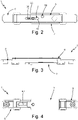
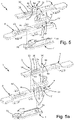
- the motion multiplication device 1 for windows or doors comprises a plurality of balls 5, 57, 59 recirculating along a ring path 4 defined in a containment body adapted to move forward as a consequence of a thrust applied to it.
- the aforesaid balls 5, 57, 59 are configured to recirculate within the ring path 4 following the advancement motion of the containment body.
- the recirculation movement of the balls 5, 57, 59 within the ring path 4 is adapted to transmit a further relative forward motion to a driven element, so that said driven element advances by an amount greater than the amount of advancement of said containment body.
- the ring path 4 constitutes a recirculation circuit of the balls 5, 57, 59 contained therein.
- a movement range imposed on the containment body results in an additional relative movement range of the driven element.
- a first range of the containment body causes the balls 5, 57, 59 to recirculate along the ring path 4 for an equal second range, so that the driven element is dragged for a total range equal to twice the range imposed on the containment body.
- the device 1 therefore acts as a movement multiplier.
- the present invention also concerns an assembly arrangement of a motion multiplication device 1 for a window or door comprising at least one profile 100, wherein:
- the device 1 comprises:
- the base slider 70 is slidable along a first section 71 of the ring path 4, while the first slider 90 is slidable along a second section 91 of the ring path 4.
- the base slider 70 and the first slider 90 are both inserted, in two distinct points 72, 92 of the ring path 4, between respective two contiguous balls 57, 59 of said plurality of balls 5, 57, 59 recirculating along the ring path 4.
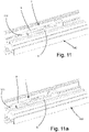
- a movement range imposed on the intermediate body 6 involves a double movement range of the covering body 9.
- a first range of the intermediate body 6 causes the balls 5, 57, 59 to recirculate along the ring path 4 for an equal second range, so that the covering body 9 is dragged for a total range equal to twice the range imposed on the intermediate body 6.
- an overall range of the covering body 9 equal to about 34 mm is obtained.
- a normal cremone/hammer handle moves the relative control rod 106 by about 17 mm through the movement device 101.
- the use of the multiplication device 1 makes it possible to double the movement range of the closing element 111 of the window or door, or of the relative driven rod 109, to about 34 mm.
- the driven element specifically the covering body 9, and the containment body, specifically the intermediate body 6, are coupled to each other by means of a linear guide coupling that allows the reciprocal longitudinal sliding thereof.
- the covering body 9 comprises a second slider 3 movable with respect to the covering body 9 itself along a guide 30 obtained in the covering body 9.
- the second slider 3 comprises an end 31 integral with the intermediate body 6.
- the guide 30 is a straight guide.
- the end 31 of the second slider 3 engages integrally in a seat 64 obtained in the intermediate body 6, for example by means of a threaded coupling.
- the base body 7 comprises a guide slider 73 sliding in a linear guide 63 obtained in the intermediate body 6.
- the base body 7 comprises at least one dowel 20 adapted to allow the fixing of the base body 7 to a profile 100 of a window or door, preferably of the type of an Allen screw.
- first section 71 and the second section 91 are straight sections.
- first section 71 and the second section 91 of the ring path 4 are parallel to the sliding direction (understood as a straight line) of the covering body 9 with respect to the intermediate body 6, as well as to the sliding direction of the intermediate body 6 with respect to the base body 7.
- the ring path 4 is comprised of two segments, preferably parallel, joined to each other by two curves, preferably in a semicircle.
- the first section 71 of the ring path 4, along which the base slider 70 slides, can be obtained in correspondence with a first segment of said two segments, while the second section 91 of the ring path 4, along which the first slider 90 slides, can be obtained in correspondence with a second segment of said two segments.
- the base slider 70 moves, along the first section 71, in a longitudinal direction with opposite direction with respect to the direction of movement of the first slider 90 along the second section 91.
- the first slider 90 may comprise a head 93 which is inserted into a corresponding seat 95 obtained in the covering body 9, and a stem 94 whose end is inserted between the balls 59 at the point 92 of the ring path 4, where the stem crosses a through hole 96 obtained in the covering body 9.
- the first slider 90 is integral in translation with the covering body 9.
- the second slider 3 comprises a head 33 that moves along a peripheral stop step 35 obtained in the guide 30, and a stem 34 that engages, for example by means of a threaded coupling, inside the seat 64 of the intermediate body 6.
- the second slider 3 is slidable with respect to the covering body 9 and integral in translation to the intermediate body 6.
- the device 1 may comprise an element for closing the window or door associated with an end 95 of the covering body 9.
- the device 1 may comprise a closure tip 111 associated with the end 95 of the covering body 9, and preferably realized as one piece with the covering body 9.
- the device 1 finds application in the systems with closure through handles, but also in all those systems where it is necessary to increase the stroke of the rod, for example one-way or two-way poles, lever poles, locks with rods, closures for slides.
- the object of the present invention has the advantage of constituting an accessory that can be easily applied to existing windows and doors in order to improve their operation, for example as a result of settling and wears of the closure components of the same window and door that occurs over time.
- Another advantage of the present invention consists in the fact that the multiplication of the motion can be obtained in a mechanically very robust manner, in an absolutely small overall dimensions and with reduced frictional forces.
- the object of the present invention thus makes it possible to realize motion multiplication mechanisms that are very resistant and not subject to breakage, which can also be applied to existing windows and doors if necessary, for example by simply modifying the manoeuvring rods that transmit the motion from the movement device associated with the handle of the window or door.
- the motion multiplication device for a window and door as conceived herein is susceptible to several modifications and variations, all falling within the invention; furthermore, all the details are replaceable by technically equivalent elements.
- the materials used, as well as their dimensions, can be of any type according to the technical requirements.
Landscapes
- Wing Frames And Configurations (AREA)
- Compression Or Coding Systems Of Tv Signals (AREA)
- Television Systems (AREA)
- Peptides Or Proteins (AREA)
- Power-Operated Mechanisms For Wings (AREA)
Applications Claiming Priority (1)
| Application Number | Priority Date | Filing Date | Title |
|---|---|---|---|
| IT102021000016772A IT202100016772A1 (it) | 2021-06-25 | 2021-06-25 | Dispositivo di moltiplicazione di moto per serramenti. |
Publications (3)
| Publication Number | Publication Date |
|---|---|
| EP4108861A1 true EP4108861A1 (de) | 2022-12-28 |
| EP4108861B1 EP4108861B1 (de) | 2024-01-03 |
| EP4108861C0 EP4108861C0 (de) | 2024-01-03 |
Family
ID=77802062
Family Applications (1)
| Application Number | Title | Priority Date | Filing Date |
|---|---|---|---|
| EP22180640.9A Active EP4108861B1 (de) | 2021-06-25 | 2022-06-23 | Bewegungsmultiplikationsvorrichtung für fenster oder türen |
Country Status (3)
| Country | Link |
|---|---|
| EP (1) | EP4108861B1 (de) |
| ES (1) | ES2973244T3 (de) |
| IT (1) | IT202100016772A1 (de) |
Citations (4)
| Publication number | Priority date | Publication date | Assignee | Title |
|---|---|---|---|---|
| DE1095709B (de) * | 1958-03-26 | 1960-12-22 | Wilhelm Frank | Umlenkvorrichtung fuer Fenster- oder Tuerbeschlagteile, insbesondere fuer Betaetigungs- und Riegelstangen |
| FR2435586A1 (fr) * | 1978-09-08 | 1980-04-04 | Ferco Int Usine Ferrures | Dispositif pour l'inversion du mouvement lineaire d'une tringle de cremone |
| GB2337556A (en) * | 1998-05-21 | 1999-11-24 | Nico Mfg | Shoot bolt mechanism |
| US20060180449A1 (en) * | 2005-02-01 | 2006-08-17 | Alexander Raisig | Switching mechanism for a fastening-bar closing device |
-
2021
- 2021-06-25 IT IT102021000016772A patent/IT202100016772A1/it unknown
-
2022
- 2022-06-23 ES ES22180640T patent/ES2973244T3/es active Active
- 2022-06-23 EP EP22180640.9A patent/EP4108861B1/de active Active
Patent Citations (4)
| Publication number | Priority date | Publication date | Assignee | Title |
|---|---|---|---|---|
| DE1095709B (de) * | 1958-03-26 | 1960-12-22 | Wilhelm Frank | Umlenkvorrichtung fuer Fenster- oder Tuerbeschlagteile, insbesondere fuer Betaetigungs- und Riegelstangen |
| FR2435586A1 (fr) * | 1978-09-08 | 1980-04-04 | Ferco Int Usine Ferrures | Dispositif pour l'inversion du mouvement lineaire d'une tringle de cremone |
| GB2337556A (en) * | 1998-05-21 | 1999-11-24 | Nico Mfg | Shoot bolt mechanism |
| US20060180449A1 (en) * | 2005-02-01 | 2006-08-17 | Alexander Raisig | Switching mechanism for a fastening-bar closing device |
Also Published As
| Publication number | Publication date |
|---|---|
| ES2973244T3 (es) | 2024-06-19 |
| EP4108861B1 (de) | 2024-01-03 |
| IT202100016772A1 (it) | 2022-12-25 |
| EP4108861C0 (de) | 2024-01-03 |
Similar Documents
| Publication | Publication Date | Title |
|---|---|---|
| AU2014202634B2 (en) | A device for opening and closing a pivoting wing | |
| US8398126B2 (en) | Multipoint lock mechanism | |
| GB2072740A (en) | Espagnolette fastening | |
| US4932691A (en) | Operating mechanism for closure fastening elements | |
| US5092640A (en) | Apparatus and method for latching sliding closures | |
| EP1816292B1 (de) | Verschluss für einen Treibstangenbeschlag | |
| EP3135842B1 (de) | Schlossvorrichtung mit öffnungsunterstützungsmechanismus und schiebetür mit schlossvorrichtung mit öffnungsunterstützungsmechanismus | |
| US9790726B2 (en) | Device for opening and closing an outwardly opening pivoting wing | |
| EP4108861B1 (de) | Bewegungsmultiplikationsvorrichtung für fenster oder türen | |
| DE602006013477D1 (de) | Flügel, insbesondere Tür oder Fenster, mit einem Verschlussmechanismus | |
| US5752727A (en) | Drive-rod type drive mechanism | |
| US11725417B1 (en) | Fenestration cam lock assemblies and methods | |
| KR102147697B1 (ko) | 적어도 리프팅 되며, 바람직하게는 슬라이딩 될 수 있는 윈도우 또는 도어의 윙을 위한 피팅장치. | |
| US2627433A (en) | Door latch | |
| GB2150972A (en) | Espagnolette operating mechanism | |
| CN209457519U (zh) | 一种自动锁机构和执手锁 | |
| RU189139U1 (ru) | Шпингалет накладной для распашных дверей | |
| EP1387029B1 (de) | Handhabe für Dreh- und Drehkippbare Fenster oder Türen | |
| EP3822439B1 (de) | Sperrmechanismus | |
| GB2304793A (en) | A slide for slidably attaching an espagnolette or locking bar to a window or door frame to facilitate positioning during mounting | |
| ITBO20050036A1 (it) | Maniglia per infissi con apertura ad anta e ad anta ribaltata | |
| CN114458082B (zh) | 用于门窗的操作装置 | |
| GB2298232A (en) | Espagnolette locking mechanism with shoot bolts and locking cams | |
| GB2291103A (en) | Espagnolette fastening | |
| EP1785562A2 (de) | Seitlich angelenkter Flügel einer Tür oder eines Fensters |
Legal Events
| Date | Code | Title | Description |
|---|---|---|---|
| PUAI | Public reference made under article 153(3) epc to a published international application that has entered the european phase |
Free format text: ORIGINAL CODE: 0009012 |
|
| STAA | Information on the status of an ep patent application or granted ep patent |
Free format text: STATUS: THE APPLICATION HAS BEEN PUBLISHED |
|
| AK | Designated contracting states |
Kind code of ref document: A1 Designated state(s): AL AT BE BG CH CY CZ DE DK EE ES FI FR GB GR HR HU IE IS IT LI LT LU LV MC MK MT NL NO PL PT RO RS SE SI SK SM TR |
|
| STAA | Information on the status of an ep patent application or granted ep patent |
Free format text: STATUS: REQUEST FOR EXAMINATION WAS MADE |
|
| P01 | Opt-out of the competence of the unified patent court (upc) registered |
Effective date: 20230530 |
|
| 17P | Request for examination filed |
Effective date: 20230615 |
|
| RBV | Designated contracting states (corrected) |
Designated state(s): AL AT BE BG CH CY CZ DE DK EE ES FI FR GB GR HR HU IE IS IT LI LT LU LV MC MK MT NL NO PL PT RO RS SE SI SK SM TR |
|
| RIN1 | Information on inventor provided before grant (corrected) |
Inventor name: LOPERFIDO, MICHELE |
|
| GRAP | Despatch of communication of intention to grant a patent |
Free format text: ORIGINAL CODE: EPIDOSNIGR1 |
|
| STAA | Information on the status of an ep patent application or granted ep patent |
Free format text: STATUS: GRANT OF PATENT IS INTENDED |
|
| INTG | Intention to grant announced |
Effective date: 20230803 |
|
| GRAS | Grant fee paid |
Free format text: ORIGINAL CODE: EPIDOSNIGR3 |
|
| GRAA | (expected) grant |
Free format text: ORIGINAL CODE: 0009210 |
|
| STAA | Information on the status of an ep patent application or granted ep patent |
Free format text: STATUS: THE PATENT HAS BEEN GRANTED |
|
| AK | Designated contracting states |
Kind code of ref document: B1 Designated state(s): AL AT BE BG CH CY CZ DE DK EE ES FI FR GB GR HR HU IE IS IT LI LT LU LV MC MK MT NL NO PL PT RO RS SE SI SK SM TR |
|
| REG | Reference to a national code |
Ref country code: GB Ref legal event code: FG4D |
|
| REG | Reference to a national code |
Ref country code: DE Ref legal event code: R096 Ref document number: 602022001538 Country of ref document: DE |
|
| REG | Reference to a national code |
Ref country code: CH Ref legal event code: EP |
|
| REG | Reference to a national code |
Ref country code: IE Ref legal event code: FG4D |
|
| U01 | Request for unitary effect filed |
Effective date: 20240129 |
|
| U07 | Unitary effect registered |
Designated state(s): AT BE BG DE DK EE FI FR IT LT LU LV MT NL PT SE SI Effective date: 20240205 |
|
| P04 | Withdrawal of opt-out of the competence of the unified patent court (upc) registered |
Effective date: 20240131 |
|
| REG | Reference to a national code |
Ref country code: ES Ref legal event code: FG2A Ref document number: 2973244 Country of ref document: ES Kind code of ref document: T3 Effective date: 20240619 |
|
| PG25 | Lapsed in a contracting state [announced via postgrant information from national office to epo] |
Ref country code: IS Free format text: LAPSE BECAUSE OF FAILURE TO SUBMIT A TRANSLATION OF THE DESCRIPTION OR TO PAY THE FEE WITHIN THE PRESCRIBED TIME-LIMIT Effective date: 20240503 |
|
| U20 | Renewal fee for the european patent with unitary effect paid |
Year of fee payment: 3 Effective date: 20240604 |
|
| PG25 | Lapsed in a contracting state [announced via postgrant information from national office to epo] |
Ref country code: GR Free format text: LAPSE BECAUSE OF FAILURE TO SUBMIT A TRANSLATION OF THE DESCRIPTION OR TO PAY THE FEE WITHIN THE PRESCRIBED TIME-LIMIT Effective date: 20240404 |
|
| PG25 | Lapsed in a contracting state [announced via postgrant information from national office to epo] |
Ref country code: HR Free format text: LAPSE BECAUSE OF FAILURE TO SUBMIT A TRANSLATION OF THE DESCRIPTION OR TO PAY THE FEE WITHIN THE PRESCRIBED TIME-LIMIT Effective date: 20240103 Ref country code: RS Free format text: LAPSE BECAUSE OF FAILURE TO SUBMIT A TRANSLATION OF THE DESCRIPTION OR TO PAY THE FEE WITHIN THE PRESCRIBED TIME-LIMIT Effective date: 20240403 |
|
| PG25 | Lapsed in a contracting state [announced via postgrant information from national office to epo] |
Ref country code: CZ Free format text: LAPSE BECAUSE OF FAILURE TO SUBMIT A TRANSLATION OF THE DESCRIPTION OR TO PAY THE FEE WITHIN THE PRESCRIBED TIME-LIMIT Effective date: 20240103 |
|
| PG25 | Lapsed in a contracting state [announced via postgrant information from national office to epo] |
Ref country code: RS Free format text: LAPSE BECAUSE OF FAILURE TO SUBMIT A TRANSLATION OF THE DESCRIPTION OR TO PAY THE FEE WITHIN THE PRESCRIBED TIME-LIMIT Effective date: 20240403 Ref country code: NO Free format text: LAPSE BECAUSE OF FAILURE TO SUBMIT A TRANSLATION OF THE DESCRIPTION OR TO PAY THE FEE WITHIN THE PRESCRIBED TIME-LIMIT Effective date: 20240403 Ref country code: IS Free format text: LAPSE BECAUSE OF FAILURE TO SUBMIT A TRANSLATION OF THE DESCRIPTION OR TO PAY THE FEE WITHIN THE PRESCRIBED TIME-LIMIT Effective date: 20240503 Ref country code: HR Free format text: LAPSE BECAUSE OF FAILURE TO SUBMIT A TRANSLATION OF THE DESCRIPTION OR TO PAY THE FEE WITHIN THE PRESCRIBED TIME-LIMIT Effective date: 20240103 Ref country code: GR Free format text: LAPSE BECAUSE OF FAILURE TO SUBMIT A TRANSLATION OF THE DESCRIPTION OR TO PAY THE FEE WITHIN THE PRESCRIBED TIME-LIMIT Effective date: 20240404 Ref country code: CZ Free format text: LAPSE BECAUSE OF FAILURE TO SUBMIT A TRANSLATION OF THE DESCRIPTION OR TO PAY THE FEE WITHIN THE PRESCRIBED TIME-LIMIT Effective date: 20240103 |
|
| PG25 | Lapsed in a contracting state [announced via postgrant information from national office to epo] |
Ref country code: PL Free format text: LAPSE BECAUSE OF FAILURE TO SUBMIT A TRANSLATION OF THE DESCRIPTION OR TO PAY THE FEE WITHIN THE PRESCRIBED TIME-LIMIT Effective date: 20240103 |
|
| PG25 | Lapsed in a contracting state [announced via postgrant information from national office to epo] |
Ref country code: PL Free format text: LAPSE BECAUSE OF FAILURE TO SUBMIT A TRANSLATION OF THE DESCRIPTION OR TO PAY THE FEE WITHIN THE PRESCRIBED TIME-LIMIT Effective date: 20240103 |
|
| REG | Reference to a national code |
Ref country code: DE Ref legal event code: R097 Ref document number: 602022001538 Country of ref document: DE |
|
| PG25 | Lapsed in a contracting state [announced via postgrant information from national office to epo] |
Ref country code: SM Free format text: LAPSE BECAUSE OF FAILURE TO SUBMIT A TRANSLATION OF THE DESCRIPTION OR TO PAY THE FEE WITHIN THE PRESCRIBED TIME-LIMIT Effective date: 20240103 |
|
| PGFP | Annual fee paid to national office [announced via postgrant information from national office to epo] |
Ref country code: ES Payment date: 20240702 Year of fee payment: 3 |
|
| PG25 | Lapsed in a contracting state [announced via postgrant information from national office to epo] |
Ref country code: SK Free format text: LAPSE BECAUSE OF FAILURE TO SUBMIT A TRANSLATION OF THE DESCRIPTION OR TO PAY THE FEE WITHIN THE PRESCRIBED TIME-LIMIT Effective date: 20240103 |
|
| PG25 | Lapsed in a contracting state [announced via postgrant information from national office to epo] |
Ref country code: SM Free format text: LAPSE BECAUSE OF FAILURE TO SUBMIT A TRANSLATION OF THE DESCRIPTION OR TO PAY THE FEE WITHIN THE PRESCRIBED TIME-LIMIT Effective date: 20240103 Ref country code: SK Free format text: LAPSE BECAUSE OF FAILURE TO SUBMIT A TRANSLATION OF THE DESCRIPTION OR TO PAY THE FEE WITHIN THE PRESCRIBED TIME-LIMIT Effective date: 20240103 Ref country code: RO Free format text: LAPSE BECAUSE OF FAILURE TO SUBMIT A TRANSLATION OF THE DESCRIPTION OR TO PAY THE FEE WITHIN THE PRESCRIBED TIME-LIMIT Effective date: 20240103 |
|
| PLBE | No opposition filed within time limit |
Free format text: ORIGINAL CODE: 0009261 |
|
| STAA | Information on the status of an ep patent application or granted ep patent |
Free format text: STATUS: NO OPPOSITION FILED WITHIN TIME LIMIT |
|
| 26N | No opposition filed |
Effective date: 20241007 |
|
| P05 | Withdrawal of opt-out of the competence of the unified patent court (upc) changed |
Free format text: CASE NUMBER: APP_5625/2024 Effective date: 20240205 |
|
| PG25 | Lapsed in a contracting state [announced via postgrant information from national office to epo] |
Ref country code: MC Free format text: LAPSE BECAUSE OF FAILURE TO SUBMIT A TRANSLATION OF THE DESCRIPTION OR TO PAY THE FEE WITHIN THE PRESCRIBED TIME-LIMIT Effective date: 20240103 |
|
| PG25 | Lapsed in a contracting state [announced via postgrant information from national office to epo] |
Ref country code: IE Free format text: LAPSE BECAUSE OF NON-PAYMENT OF DUE FEES Effective date: 20240623 |
|
| U20 | Renewal fee for the european patent with unitary effect paid |
Year of fee payment: 4 Effective date: 20250620 |
|
| PG25 | Lapsed in a contracting state [announced via postgrant information from national office to epo] |
Ref country code: CY Free format text: LAPSE BECAUSE OF FAILURE TO SUBMIT A TRANSLATION OF THE DESCRIPTION OR TO PAY THE FEE WITHIN THE PRESCRIBED TIME-LIMIT; INVALID AB INITIO Effective date: 20220623 |
|
| REG | Reference to a national code |
Ref country code: CH Ref legal event code: H13 Free format text: ST27 STATUS EVENT CODE: U-0-0-H10-H13 (AS PROVIDED BY THE NATIONAL OFFICE) Effective date: 20260127 |
|
| PG25 | Lapsed in a contracting state [announced via postgrant information from national office to epo] |
Ref country code: HU Free format text: LAPSE BECAUSE OF FAILURE TO SUBMIT A TRANSLATION OF THE DESCRIPTION OR TO PAY THE FEE WITHIN THE PRESCRIBED TIME-LIMIT; INVALID AB INITIO Effective date: 20220623 |
|
| PG25 | Lapsed in a contracting state [announced via postgrant information from national office to epo] |
Ref country code: CH Free format text: LAPSE BECAUSE OF NON-PAYMENT OF DUE FEES Effective date: 20250630 |
|
| U20 | Renewal fee for the european patent with unitary effect paid |
Year of fee payment: 5 Effective date: 20260331 |