EP4108877A1 - Charnière pour une porte, une fenêtre ou un composant similaire - Google Patents
Charnière pour une porte, une fenêtre ou un composant similaire Download PDFInfo
- Publication number
- EP4108877A1 EP4108877A1 EP22175138.1A EP22175138A EP4108877A1 EP 4108877 A1 EP4108877 A1 EP 4108877A1 EP 22175138 A EP22175138 A EP 22175138A EP 4108877 A1 EP4108877 A1 EP 4108877A1
- Authority
- EP
- European Patent Office
- Prior art keywords
- hinge
- wing
- pin
- frame
- door
- Prior art date
- Legal status (The legal status is an assumption and is not a legal conclusion. Google has not performed a legal analysis and makes no representation as to the accuracy of the status listed.)
- Granted
Links
Images
Classifications
-
- E—FIXED CONSTRUCTIONS
- E05—LOCKS; KEYS; WINDOW OR DOOR FITTINGS; SAFES
- E05D—HINGES OR SUSPENSION DEVICES FOR DOORS, WINDOWS OR WINGS
- E05D7/00—Hinges or pivots of special construction
- E05D7/10—Hinges or pivots of special construction to allow easy separation or connection of the parts at the hinge axis
- E05D7/1005—Hinges or pivots of special construction to allow easy separation or connection of the parts at the hinge axis by axially moving free pins, balls or sockets
-
- E—FIXED CONSTRUCTIONS
- E05—LOCKS; KEYS; WINDOW OR DOOR FITTINGS; SAFES
- E05D—HINGES OR SUSPENSION DEVICES FOR DOORS, WINDOWS OR WINGS
- E05D3/00—Hinges with pins
- E05D3/02—Hinges with pins with one pin
-
- E—FIXED CONSTRUCTIONS
- E05—LOCKS; KEYS; WINDOW OR DOOR FITTINGS; SAFES
- E05D—HINGES OR SUSPENSION DEVICES FOR DOORS, WINDOWS OR WINGS
- E05D5/00—Construction of single parts, e.g. the parts for attachment
- E05D5/10—Pins, sockets or sleeves; Removable pins
- E05D5/12—Securing pins in sockets, movably or not
- E05D5/121—Screw-threaded pins
-
- E—FIXED CONSTRUCTIONS
- E05—LOCKS; KEYS; WINDOW OR DOOR FITTINGS; SAFES
- E05D—HINGES OR SUSPENSION DEVICES FOR DOORS, WINDOWS OR WINGS
- E05D7/00—Hinges or pivots of special construction
- E05D7/0009—Adjustable hinges
- E05D7/0018—Adjustable hinges at the hinge axis
- E05D7/0045—Adjustable hinges at the hinge axis in a radial direction
- E05D7/0054—Adjustable hinges at the hinge axis in a radial direction by means of eccentric parts
-
- E—FIXED CONSTRUCTIONS
- E05—LOCKS; KEYS; WINDOW OR DOOR FITTINGS; SAFES
- E05D—HINGES OR SUSPENSION DEVICES FOR DOORS, WINDOWS OR WINGS
- E05D5/00—Construction of single parts, e.g. the parts for attachment
- E05D5/10—Pins, sockets or sleeves; Removable pins
- E05D5/12—Securing pins in sockets, movably or not
- E05D5/121—Screw-threaded pins
- E05D2005/122—Screw-threaded pins externally threaded
-
- E—FIXED CONSTRUCTIONS
- E05—LOCKS; KEYS; WINDOW OR DOOR FITTINGS; SAFES
- E05D—HINGES OR SUSPENSION DEVICES FOR DOORS, WINDOWS OR WINGS
- E05D7/00—Hinges or pivots of special construction
- E05D7/10—Hinges or pivots of special construction to allow easy separation or connection of the parts at the hinge axis
- E05D7/1005—Hinges or pivots of special construction to allow easy separation or connection of the parts at the hinge axis by axially moving free pins, balls or sockets
- E05D2007/1027—Hinges or pivots of special construction to allow easy separation or connection of the parts at the hinge axis by axially moving free pins, balls or sockets by axially moving free pins
-
- E—FIXED CONSTRUCTIONS
- E05—LOCKS; KEYS; WINDOW OR DOOR FITTINGS; SAFES
- E05Y—INDEXING SCHEME ASSOCIATED WITH SUBCLASSES E05D AND E05F, RELATING TO CONSTRUCTION ELEMENTS, ELECTRIC CONTROL, POWER SUPPLY, POWER SIGNAL OR TRANSMISSION, USER INTERFACES, MOUNTING OR COUPLING, DETAILS, ACCESSORIES, AUXILIARY OPERATIONS NOT OTHERWISE PROVIDED FOR, APPLICATION THEREOF
- E05Y2900/00—Application of doors, windows, wings or fittings thereof
- E05Y2900/10—Application of doors, windows, wings or fittings thereof for buildings or parts thereof
- E05Y2900/13—Type of wing
- E05Y2900/148—Windows
Definitions
- the invention relates to a hinge for a door, a window or a similar component, with a component-side hinge wing and a frame-side hinge wing, which can be rotated relative to one another about an axis of a hinge pin connecting them to one another, the component-side hinge wing being pivotably mounted on the frame-side hinge wing when installed is.
- the hinge wings are usually provided with a sleeve for receiving the hinge pin and a flange-like part designed for attaching the hinge leaf to a door or a door frame.
- a sleeve for receiving the hinge pin
- a flange-like part designed for attaching the hinge leaf to a door or a door frame.
- the aim is to dimension the doors or windows for space or architectural reasons in such a way that they protrude almost to the ceiling on the top side, so that when installed, there is a gap between the tops of the doors or windows and the ceiling a very small distance of only a few millimeters may be present. This makes the assembly and disassembly of the doors or windows very cumbersome, because it is then only possible by removing or attaching the hinge leaf.
- the invention has for its object to overcome these disadvantages and to create a hinge of the type mentioned that allows easy and convenient assembly and disassembly of doors, windows or similar components with simple means, even if there is only a small gap between them and of the ceiling is present due to special structural conditions.
- this object is achieved in that the hinge pin and one hinge wing are provided with an adjusting mechanism, by means of which the hinge pin in this one hinge wing to the extent that it can be adjusted in both axial directions so that in the released position it is preferably outside the side adjacent to the other hinge wing, while in the assembled position it engages in this hinge wing for the pivot bearing.
- This adjusting mechanism is very advantageously implemented as a screw connection of the hinge pin in the hinge wing, which is designed as a thread, a bayonet or the like.
- the hinge pin can thus be easily adjusted in the direction of the axis of rotation with an Allen key or the like.
- the invention further provides that the hinge pin is guided, for example in the door-side hinge wing, in an eccentric sleeve that is axially parallel to the hinge pin and whose angle of rotation can be adjusted.
- the hinge pin is guided, for example in the door-side hinge wing, in an eccentric sleeve that is axially parallel to the hinge pin and whose angle of rotation can be adjusted.
- the invention also provides that the hinge pin is provided with the adjustment mechanism in the part protruding into the eccentric sleeve with a smaller diameter than in the door-frame-side hinge wing.
- the hinge pin In order to precisely determine the final installation position of the hinge pin, it can be pressed according to the invention up to a bearing element of the eccentric sleeve.
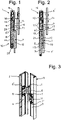
- the hinge 1 shown is used for pivoting a door 2 on a door frame 3, which preferably have metal profile frames 4, 5.
- the hinge 1 consists essentially of a door-side and a frame-side hinge wing 6, 7, which are mounted pivotably relative to one another about the axis 8 of a hinge pin 9 connecting them to one another and each consist of a shaped sleeve for receiving the hinge pin 9 and a wing for fastening Assemble the hinge leaf on the door and door frame.
- the hinge wings 6, 7 are preferably attached to clamping plates 6', 7' by means of screws 11 on the profile frame 4, 5 of the door and door frame.
- the hinge 1 can also be provided for a window or a similar component, and preferably for a door or the like, two or more hinges can be provided one above the other.
- the hinge wing 6 on the door side is held pivotably on the hinge wing 7 on the frame side. With its lower or upper side, the door is normally guided with a small gap above the floor or below the ceiling.
- the hinge bolt 9 and one hinge leaf 6, 7 are provided with an adjustment mechanism 10, by means of which the hinge bolt 9 in this one hinge leaf 7 can be adjusted in both axial directions to such an extent that in the released, retracted position it is preferably at a distance from the adjacent lower side edge 6 " of the other hinge leaf 6, as in 2 apparent is.
- this hinge pin 9 engages in this hinge wing 6 for the pivot bearing, as is shown in 1 is clarified.
- the adjusting mechanism 10 is advantageously arranged in the lower hinge wing 7 on the frame side when the axis 8 is arranged vertically. In principle, this could also be placed in the upper hinge wing, whereby the latter would have to be assigned to the door or the pivoting component and the lower supporting hinge wing would therefore have to be fixed in the frame. The hinge pin would then be actuated from the top in the axial direction.
- the adjustment mechanism 10 is expediently provided as a screw connection between the hinge pin 9 and the hinge wing 7, which can be designed as a thread, a bayonet or the like.
- the hinge pin 9 is preferably provided with an external thread 13 in a guide sleeve 12 receiving it with a corresponding internal thread 13 ′ of the hinge leaf 7 on the door frame side.
- the hinge pin 9 By screwing the hinge pin 9 into the guide sleeve 12, it can be adjusted in height in both directions by turning it downwards in one direction until its upper end lies below the side 6" of the door-side hinge leaf 6, while in the other direction it screwed at the top and inserted into a bore 17 of the hinge leaf 6 on the door side.
- This internal thread 13' of the screw connection is advantageously worked in at least in the lower part of the guide sleeve 12 and the external thread 13 in the hinge pin 9 over such a length that it can be pulled back in the released position, as in FIG 2 is shown, is still partially screwed into this guide sleeve 12 .
- the door-side hinge leaf 6 is also provided with an eccentric sleeve 14 with the bore 17, in which the hinge pin 9 is guided in the installed state.
- the eccentric sleeve 14 can be rotated axially parallel to the axis 8 of the hinge pin 9 in a sleeve 15 of the hinge wing 6 receiving it.
- the eccentric sleeve 14 is turned in the sleeve 15 until it reaches the required angular position, in which it is then fixed with a head screw 16 .
- the angle of rotation of the eccentric sleeve 14 the door to the frame can be adjusted transversely to the axial direction in the x and y directions.
- Plastic bushings 17' are inserted in the eccentric sleeve 14 for easier guidance of the hinge pin 9, the latter being able to be pressed on the upper side up to a bearing element 18 of the eccentric sleeve 14 with a spherical pressure element 19. This determines the final position of the hinge pin 9 after the door has been installed.
- a gap is provided between the two hinge wings 6, 7, so that the two would not touch and wear out.
- this serves to insert a head screw 22 or the like into the hinge pin 9 and into the guide sleeve 12 of the hinge leaf 7.
- the latter can be pressed against the hinge pin 9 with a certain torque, which means that locking the same can be omitted.
- the hinge pin 9 in the present embodiment is designed in such a way that it has a smaller diameter in the part 21 protruding into the eccentric sleeve 14 than in the hinge wing 7 on the door frame side.
- the wall thickness of the eccentric sleeve 14 is at least partially compensated, and the sleeve-shaped part of the hinge wing 6 can be dimensioned as slim as in the hinge wing 7 .
- the cap screws 16, 22 are designed to be operated with one and the same special key, for example an Allen key can. This is inserted axially into the head screws and can be rotated around their axis.
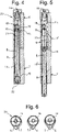
- the hinge 20 according to Figures 4 to 6 differs from the hinge 1 after Figures 1 to 3 only in that, instead of wings, it has triangular parts 26, 27 in cross-section as hinge wings 6, 7, which are suitable for being welded directly to the door or the door frame. Otherwise, the same reference numerals have been used for the same components as in the hinge 1 and it is therefore not discussed in detail below.
- FIG. 6 shows a plan view of the hinge 20 in three different positions of the two hinge leaves 6, 7 in relation to one another, in which the lower hinge leaf 7 can be positioned differently in relation to the upper hinge leaf 6 depending on the angle of rotation, so that the door can be rotated to the frame transversely to the axis direction in x and y -Direction can be adjusted as mentioned to set the door flush in the frame when closed.
- the hinge could be built without such an eccentric sleeve and/or without this bearing element.
- the hinge pin can be designed in one or more parts. In principle, this could also be designed in the form of a sleeve, for example in order to route an electric cable through it.
- the lower supporting hinge wing could be mounted on the frame side. This would then be provided with or without an adjustable eccentric sleeve.
Landscapes
- Engineering & Computer Science (AREA)
- Mechanical Engineering (AREA)
- Hinges (AREA)
Applications Claiming Priority (1)
| Application Number | Priority Date | Filing Date | Title |
|---|---|---|---|
| CH000720/2021A CH718757B1 (de) | 2021-06-22 | 2021-06-22 | Scharnier für eine Türe oder ein Fenster als Bauteil. |
Publications (2)
| Publication Number | Publication Date |
|---|---|
| EP4108877A1 true EP4108877A1 (fr) | 2022-12-28 |
| EP4108877B1 EP4108877B1 (fr) | 2024-10-09 |
Family
ID=81846452
Family Applications (1)
| Application Number | Title | Priority Date | Filing Date |
|---|---|---|---|
| EP22175138.1A Active EP4108877B1 (fr) | 2021-06-22 | 2022-05-24 | Charnière pour une porte, une fenêtre ou un composant similaire |
Country Status (2)
| Country | Link |
|---|---|
| EP (1) | EP4108877B1 (fr) |
| CH (1) | CH718757B1 (fr) |
Citations (4)
| Publication number | Priority date | Publication date | Assignee | Title |
|---|---|---|---|---|
| DE19810081A1 (de) * | 1998-03-09 | 1999-09-16 | Schuering Fenstertech | Höhenverstellbare Bandzapfenlagerung |
| US6212734B1 (en) * | 1999-09-13 | 2001-04-10 | Robert R. Commons | Adjustable hinge |
| WO2007145578A1 (fr) * | 2006-06-16 | 2007-12-21 | Assa Ab | Charnière réglable en hauteur |
| US20080235910A1 (en) * | 2007-03-30 | 2008-10-02 | Umback Trevor J | Hinge |
-
2021
- 2021-06-22 CH CH000720/2021A patent/CH718757B1/de unknown
-
2022
- 2022-05-24 EP EP22175138.1A patent/EP4108877B1/fr active Active
Patent Citations (4)
| Publication number | Priority date | Publication date | Assignee | Title |
|---|---|---|---|---|
| DE19810081A1 (de) * | 1998-03-09 | 1999-09-16 | Schuering Fenstertech | Höhenverstellbare Bandzapfenlagerung |
| US6212734B1 (en) * | 1999-09-13 | 2001-04-10 | Robert R. Commons | Adjustable hinge |
| WO2007145578A1 (fr) * | 2006-06-16 | 2007-12-21 | Assa Ab | Charnière réglable en hauteur |
| US20080235910A1 (en) * | 2007-03-30 | 2008-10-02 | Umback Trevor J | Hinge |
Also Published As
| Publication number | Publication date |
|---|---|
| EP4108877B1 (fr) | 2024-10-09 |
| CH718757B1 (de) | 2024-05-31 |
| CH718757A2 (de) | 2022-12-30 |
Similar Documents
| Publication | Publication Date | Title |
|---|---|---|
| AT394081B (de) | Verstellbares tuer- und fensterband | |
| EP0259618B1 (fr) | Penture de porte et fenêtre, réglable pendant et après le montage | |
| EP2158372B1 (fr) | Charnière de porte ou de fenêtre | |
| DE3539276C1 (fr) | ||
| DE102010047774B4 (de) | Türscharnier | |
| DE3843680C2 (de) | Verdeckt angeordneter Beschlag für Schwenklager von Türen, Fenstern oder dergleichen | |
| EP2503084B1 (fr) | Charnière réglable | |
| EP2949844B1 (fr) | Agencement de bande pour portes, fenêtres ou analogues, doté d'un dispositif de réglage de jeu de joint | |
| CH645155A5 (de) | Tuerband. | |
| EP1001124B1 (fr) | Ferrure de charnière pour un volet | |
| EP1577476B1 (fr) | Charnière pour maintenir de façon articulée une porte ou une fenêtre sur un cadre | |
| EP3425155A1 (fr) | Dispositif de protection anti-pince doigt pour une porte | |
| EP4108877B1 (fr) | Charnière pour une porte, une fenêtre ou un composant similaire | |
| EP4045745B1 (fr) | Palier d'angle | |
| EP1413700A2 (fr) | Charnière pour portes et autres éléments de construction | |
| EP3029240A1 (fr) | Ferrure d'angle dotée d'une plage de réglage variable | |
| WO1995024536A1 (fr) | Battant de porte | |
| DE29904129U1 (de) | Verschwindscharnier | |
| DE3001070A1 (de) | Eckgelenk fuer drehkippfenster, -tueren o.dgl. | |
| EP1659246A1 (fr) | Charnière pour volets | |
| EP3278693B1 (fr) | Ferrure de porte coulissante | |
| DE19918283B4 (de) | Tür- oder Fensterdrehband | |
| EP1038486B1 (fr) | Jeu de pièces pour cloisons de douches | |
| EP3029227A1 (fr) | Ferrure dotée d'une plage de serrage réglable | |
| DE19647202B4 (de) | Betätigungseinrichtung zum Öffnen und Schließen eines Flügels |
Legal Events
| Date | Code | Title | Description |
|---|---|---|---|
| PUAI | Public reference made under article 153(3) epc to a published international application that has entered the european phase |
Free format text: ORIGINAL CODE: 0009012 |
|
| STAA | Information on the status of an ep patent application or granted ep patent |
Free format text: STATUS: THE APPLICATION HAS BEEN PUBLISHED |
|
| AK | Designated contracting states |
Kind code of ref document: A1 Designated state(s): AL AT BE BG CH CY CZ DE DK EE ES FI FR GB GR HR HU IE IS IT LI LT LU LV MC MK MT NL NO PL PT RO RS SE SI SK SM TR |
|
| STAA | Information on the status of an ep patent application or granted ep patent |
Free format text: STATUS: REQUEST FOR EXAMINATION WAS MADE |
|
| 17P | Request for examination filed |
Effective date: 20230606 |
|
| RBV | Designated contracting states (corrected) |
Designated state(s): AL AT BE BG CH CY CZ DE DK EE ES FI FR GB GR HR HU IE IS IT LI LT LU LV MC MK MT NL NO PL PT RO RS SE SI SK SM TR |
|
| GRAP | Despatch of communication of intention to grant a patent |
Free format text: ORIGINAL CODE: EPIDOSNIGR1 |
|
| STAA | Information on the status of an ep patent application or granted ep patent |
Free format text: STATUS: GRANT OF PATENT IS INTENDED |
|
| INTG | Intention to grant announced |
Effective date: 20240620 |
|
| GRAS | Grant fee paid |
Free format text: ORIGINAL CODE: EPIDOSNIGR3 |
|
| GRAA | (expected) grant |
Free format text: ORIGINAL CODE: 0009210 |
|
| STAA | Information on the status of an ep patent application or granted ep patent |
Free format text: STATUS: THE PATENT HAS BEEN GRANTED |
|
| AK | Designated contracting states |
Kind code of ref document: B1 Designated state(s): AL AT BE BG CH CY CZ DE DK EE ES FI FR GB GR HR HU IE IS IT LI LT LU LV MC MK MT NL NO PL PT RO RS SE SI SK SM TR |
|
| REG | Reference to a national code |
Ref country code: CH Ref legal event code: EP |
|
| REG | Reference to a national code |
Ref country code: DE Ref legal event code: R096 Ref document number: 502022001834 Country of ref document: DE |
|
| REG | Reference to a national code |
Ref country code: IE Ref legal event code: FG4D Free format text: LANGUAGE OF EP DOCUMENT: GERMAN |
|
| REG | Reference to a national code |
Ref country code: LT Ref legal event code: MG9D |
|
| REG | Reference to a national code |
Ref country code: NL Ref legal event code: MP Effective date: 20241009 |
|
| PG25 | Lapsed in a contracting state [announced via postgrant information from national office to epo] |
Ref country code: NL Free format text: LAPSE BECAUSE OF FAILURE TO SUBMIT A TRANSLATION OF THE DESCRIPTION OR TO PAY THE FEE WITHIN THE PRESCRIBED TIME-LIMIT Effective date: 20241009 |
|
| PG25 | Lapsed in a contracting state [announced via postgrant information from national office to epo] |
Ref country code: NL Free format text: LAPSE BECAUSE OF FAILURE TO SUBMIT A TRANSLATION OF THE DESCRIPTION OR TO PAY THE FEE WITHIN THE PRESCRIBED TIME-LIMIT Effective date: 20241009 |
|
| PG25 | Lapsed in a contracting state [announced via postgrant information from national office to epo] |
Ref country code: HR Free format text: LAPSE BECAUSE OF FAILURE TO SUBMIT A TRANSLATION OF THE DESCRIPTION OR TO PAY THE FEE WITHIN THE PRESCRIBED TIME-LIMIT Effective date: 20241009 Ref country code: IS Free format text: LAPSE BECAUSE OF FAILURE TO SUBMIT A TRANSLATION OF THE DESCRIPTION OR TO PAY THE FEE WITHIN THE PRESCRIBED TIME-LIMIT Effective date: 20250209 Ref country code: PT Free format text: LAPSE BECAUSE OF FAILURE TO SUBMIT A TRANSLATION OF THE DESCRIPTION OR TO PAY THE FEE WITHIN THE PRESCRIBED TIME-LIMIT Effective date: 20250210 |
|
| PG25 | Lapsed in a contracting state [announced via postgrant information from national office to epo] |
Ref country code: FI Free format text: LAPSE BECAUSE OF FAILURE TO SUBMIT A TRANSLATION OF THE DESCRIPTION OR TO PAY THE FEE WITHIN THE PRESCRIBED TIME-LIMIT Effective date: 20241009 |
|
| PG25 | Lapsed in a contracting state [announced via postgrant information from national office to epo] |
Ref country code: BG Free format text: LAPSE BECAUSE OF FAILURE TO SUBMIT A TRANSLATION OF THE DESCRIPTION OR TO PAY THE FEE WITHIN THE PRESCRIBED TIME-LIMIT Effective date: 20241009 |
|
| PG25 | Lapsed in a contracting state [announced via postgrant information from national office to epo] |
Ref country code: ES Free format text: LAPSE BECAUSE OF FAILURE TO SUBMIT A TRANSLATION OF THE DESCRIPTION OR TO PAY THE FEE WITHIN THE PRESCRIBED TIME-LIMIT Effective date: 20241009 |
|
| PG25 | Lapsed in a contracting state [announced via postgrant information from national office to epo] |
Ref country code: NO Free format text: LAPSE BECAUSE OF FAILURE TO SUBMIT A TRANSLATION OF THE DESCRIPTION OR TO PAY THE FEE WITHIN THE PRESCRIBED TIME-LIMIT Effective date: 20250109 |
|
| PG25 | Lapsed in a contracting state [announced via postgrant information from national office to epo] |
Ref country code: LV Free format text: LAPSE BECAUSE OF FAILURE TO SUBMIT A TRANSLATION OF THE DESCRIPTION OR TO PAY THE FEE WITHIN THE PRESCRIBED TIME-LIMIT Effective date: 20241009 Ref country code: GR Free format text: LAPSE BECAUSE OF FAILURE TO SUBMIT A TRANSLATION OF THE DESCRIPTION OR TO PAY THE FEE WITHIN THE PRESCRIBED TIME-LIMIT Effective date: 20250110 |
|
| PG25 | Lapsed in a contracting state [announced via postgrant information from national office to epo] |
Ref country code: PL Free format text: LAPSE BECAUSE OF FAILURE TO SUBMIT A TRANSLATION OF THE DESCRIPTION OR TO PAY THE FEE WITHIN THE PRESCRIBED TIME-LIMIT Effective date: 20241009 |
|
| PG25 | Lapsed in a contracting state [announced via postgrant information from national office to epo] |
Ref country code: RS Free format text: LAPSE BECAUSE OF FAILURE TO SUBMIT A TRANSLATION OF THE DESCRIPTION OR TO PAY THE FEE WITHIN THE PRESCRIBED TIME-LIMIT Effective date: 20250109 |
|
| PG25 | Lapsed in a contracting state [announced via postgrant information from national office to epo] |
Ref country code: SM Free format text: LAPSE BECAUSE OF FAILURE TO SUBMIT A TRANSLATION OF THE DESCRIPTION OR TO PAY THE FEE WITHIN THE PRESCRIBED TIME-LIMIT Effective date: 20241009 |
|
| PG25 | Lapsed in a contracting state [announced via postgrant information from national office to epo] |
Ref country code: DK Free format text: LAPSE BECAUSE OF FAILURE TO SUBMIT A TRANSLATION OF THE DESCRIPTION OR TO PAY THE FEE WITHIN THE PRESCRIBED TIME-LIMIT Effective date: 20241009 |
|
| REG | Reference to a national code |
Ref country code: DE Ref legal event code: R097 Ref document number: 502022001834 Country of ref document: DE |
|
| PGFP | Annual fee paid to national office [announced via postgrant information from national office to epo] |
Ref country code: IT Payment date: 20250531 Year of fee payment: 4 Ref country code: BE Payment date: 20250521 Year of fee payment: 4 |
|
| PG25 | Lapsed in a contracting state [announced via postgrant information from national office to epo] |
Ref country code: EE Free format text: LAPSE BECAUSE OF FAILURE TO SUBMIT A TRANSLATION OF THE DESCRIPTION OR TO PAY THE FEE WITHIN THE PRESCRIBED TIME-LIMIT Effective date: 20241009 |
|
| PGFP | Annual fee paid to national office [announced via postgrant information from national office to epo] |
Ref country code: FR Payment date: 20250411 Year of fee payment: 4 |
|
| PGFP | Annual fee paid to national office [announced via postgrant information from national office to epo] |
Ref country code: CH Payment date: 20250601 Year of fee payment: 4 |
|
| PG25 | Lapsed in a contracting state [announced via postgrant information from national office to epo] |
Ref country code: RO Free format text: LAPSE BECAUSE OF FAILURE TO SUBMIT A TRANSLATION OF THE DESCRIPTION OR TO PAY THE FEE WITHIN THE PRESCRIBED TIME-LIMIT Effective date: 20241009 |
|
| PGFP | Annual fee paid to national office [announced via postgrant information from national office to epo] |
Ref country code: AT Payment date: 20250721 Year of fee payment: 4 |
|
| PG25 | Lapsed in a contracting state [announced via postgrant information from national office to epo] |
Ref country code: SK Free format text: LAPSE BECAUSE OF FAILURE TO SUBMIT A TRANSLATION OF THE DESCRIPTION OR TO PAY THE FEE WITHIN THE PRESCRIBED TIME-LIMIT Effective date: 20241009 |
|
| PG25 | Lapsed in a contracting state [announced via postgrant information from national office to epo] |
Ref country code: CZ Free format text: LAPSE BECAUSE OF FAILURE TO SUBMIT A TRANSLATION OF THE DESCRIPTION OR TO PAY THE FEE WITHIN THE PRESCRIBED TIME-LIMIT Effective date: 20241009 |
|
| PLBE | No opposition filed within time limit |
Free format text: ORIGINAL CODE: 0009261 |
|
| STAA | Information on the status of an ep patent application or granted ep patent |
Free format text: STATUS: NO OPPOSITION FILED WITHIN TIME LIMIT |
|
| PG25 | Lapsed in a contracting state [announced via postgrant information from national office to epo] |
Ref country code: SE Free format text: LAPSE BECAUSE OF FAILURE TO SUBMIT A TRANSLATION OF THE DESCRIPTION OR TO PAY THE FEE WITHIN THE PRESCRIBED TIME-LIMIT Effective date: 20241009 |
|
| 26N | No opposition filed |
Effective date: 20250710 |
|
| PGFP | Annual fee paid to national office [announced via postgrant information from national office to epo] |
Ref country code: DE Payment date: 20250722 Year of fee payment: 4 |
|
| PG25 | Lapsed in a contracting state [announced via postgrant information from national office to epo] |
Ref country code: LU Free format text: LAPSE BECAUSE OF NON-PAYMENT OF DUE FEES Effective date: 20250524 |
|
| PG25 | Lapsed in a contracting state [announced via postgrant information from national office to epo] |
Ref country code: MC Free format text: LAPSE BECAUSE OF FAILURE TO SUBMIT A TRANSLATION OF THE DESCRIPTION OR TO PAY THE FEE WITHIN THE PRESCRIBED TIME-LIMIT Effective date: 20241009 |
|
| REG | Reference to a national code |
Ref country code: DE Ref legal event code: R082 Ref document number: 502022001834 Country of ref document: DE Representative=s name: DR. RIEBLING & PARTNER PATENTANWAELTE MBB, DE |
|
| PG25 | Lapsed in a contracting state [announced via postgrant information from national office to epo] |
Ref country code: IE Free format text: LAPSE BECAUSE OF NON-PAYMENT OF DUE FEES Effective date: 20250524 |