EP4108880B1 - Dispositif de fermeture destiné à l'étanchéité des ouvertures ou des espaces de bâtiment - Google Patents
Dispositif de fermeture destiné à l'étanchéité des ouvertures ou des espaces de bâtiment Download PDFInfo
- Publication number
- EP4108880B1 EP4108880B1 EP22173240.7A EP22173240A EP4108880B1 EP 4108880 B1 EP4108880 B1 EP 4108880B1 EP 22173240 A EP22173240 A EP 22173240A EP 4108880 B1 EP4108880 B1 EP 4108880B1
- Authority
- EP
- European Patent Office
- Prior art keywords
- sealing
- plane
- closure device
- section
- structural element
- Prior art date
- Legal status (The legal status is an assumption and is not a legal conclusion. Google has not performed a legal analysis and makes no representation as to the accuracy of the status listed.)
- Active
Links
Images


Classifications
-
- E—FIXED CONSTRUCTIONS
- E06—DOORS, WINDOWS, SHUTTERS, OR ROLLER BLINDS IN GENERAL; LADDERS
- E06B—FIXED OR MOVABLE CLOSURES FOR OPENINGS IN BUILDINGS, VEHICLES, FENCES OR LIKE ENCLOSURES IN GENERAL, e.g. DOORS, WINDOWS, BLINDS, GATES
- E06B7/00—Special arrangements or measures in connection with doors or windows
- E06B7/16—Sealing arrangements on wings or parts co-operating with the wings
- E06B7/22—Sealing arrangements on wings or parts co-operating with the wings by means of elastic edgings, e.g. elastic rubber tubes; by means of resilient edgings, e.g. felt or plush strips, resilient metal strips
- E06B7/23—Plastic, sponge rubber, or like strips or tubes
- E06B7/2318—Plastic, sponge rubber, or like strips or tubes by applying over- or under-pressure, e.g. inflatable
-
- E—FIXED CONSTRUCTIONS
- E06—DOORS, WINDOWS, SHUTTERS, OR ROLLER BLINDS IN GENERAL; LADDERS
- E06B—FIXED OR MOVABLE CLOSURES FOR OPENINGS IN BUILDINGS, VEHICLES, FENCES OR LIKE ENCLOSURES IN GENERAL, e.g. DOORS, WINDOWS, BLINDS, GATES
- E06B7/00—Special arrangements or measures in connection with doors or windows
- E06B7/16—Sealing arrangements on wings or parts co-operating with the wings
- E06B7/22—Sealing arrangements on wings or parts co-operating with the wings by means of elastic edgings, e.g. elastic rubber tubes; by means of resilient edgings, e.g. felt or plush strips, resilient metal strips
- E06B7/23—Plastic, sponge rubber, or like strips or tubes
- E06B7/2301—Plastic, sponge rubber, or like strips or tubes without an integrally formed part for fixing the edging
- E06B7/2303—Plastic, sponge rubber, or like strips or tubes without an integrally formed part for fixing the edging hollow
-
- E—FIXED CONSTRUCTIONS
- E06—DOORS, WINDOWS, SHUTTERS, OR ROLLER BLINDS IN GENERAL; LADDERS
- E06B—FIXED OR MOVABLE CLOSURES FOR OPENINGS IN BUILDINGS, VEHICLES, FENCES OR LIKE ENCLOSURES IN GENERAL, e.g. DOORS, WINDOWS, BLINDS, GATES
- E06B7/00—Special arrangements or measures in connection with doors or windows
- E06B7/16—Sealing arrangements on wings or parts co-operating with the wings
- E06B7/22—Sealing arrangements on wings or parts co-operating with the wings by means of elastic edgings, e.g. elastic rubber tubes; by means of resilient edgings, e.g. felt or plush strips, resilient metal strips
- E06B7/23—Plastic, sponge rubber, or like strips or tubes
- E06B7/2305—Plastic, sponge rubber, or like strips or tubes with an integrally formed part for fixing the edging
- E06B7/2307—Plastic, sponge rubber, or like strips or tubes with an integrally formed part for fixing the edging with a single sealing-line or -plane between the wing and the part co-operating with the wing
- E06B7/2309—Plastic, sponge rubber, or like strips or tubes with an integrally formed part for fixing the edging with a single sealing-line or -plane between the wing and the part co-operating with the wing with a hollow sealing part
-
- E—FIXED CONSTRUCTIONS
- E06—DOORS, WINDOWS, SHUTTERS, OR ROLLER BLINDS IN GENERAL; LADDERS
- E06B—FIXED OR MOVABLE CLOSURES FOR OPENINGS IN BUILDINGS, VEHICLES, FENCES OR LIKE ENCLOSURES IN GENERAL, e.g. DOORS, WINDOWS, BLINDS, GATES
- E06B3/00—Window sashes, door leaves, or like elements for closing wall or like openings; Layout of fixed or moving closures, e.g. windows in wall or like openings; Features of rigidly-mounted outer frames relating to the mounting of wing frames
- E06B3/70—Door leaves
- E06B3/72—Door leaves consisting of frame and panels, e.g. of raised panel type
-
- E—FIXED CONSTRUCTIONS
- E06—DOORS, WINDOWS, SHUTTERS, OR ROLLER BLINDS IN GENERAL; LADDERS
- E06B—FIXED OR MOVABLE CLOSURES FOR OPENINGS IN BUILDINGS, VEHICLES, FENCES OR LIKE ENCLOSURES IN GENERAL, e.g. DOORS, WINDOWS, BLINDS, GATES
- E06B5/00—Doors, windows, or like closures for special purposes; Border constructions therefor
- E06B5/10—Doors, windows, or like closures for special purposes; Border constructions therefor for protection against air-raid or other war-like action; for other protective purposes
- E06B5/16—Fireproof doors or similar closures; Adaptations of fixed constructions therefor
- E06B5/164—Sealing arrangements between the door or window and its frame, e.g. intumescent seals specially adapted therefor
Definitions
- the present invention relates to a closure device for sealing building openings or rooms.
- Closure devices are used for different applications and are used in particular to protect a separable area from physical influences such as pressure, temperature, water and/or steam.
- Security doors or property protection doors are flat locking devices in which a flat structural element can be held in a frame and fixed in a closed position.
- the doors can be designed as fire doors, smoke protection doors, pressure doors or similar and form a pressure-, temperature-, water- and/or smoke-tight connection with the frame so that an area separated by the door can be protected from physical influences.
- the separable area can be a building or section of a building or, for example, a single room.
- Security doors and property protection doors are used, for example, in stairwells, as apartment doors or for commercial premises.
- Property protection doors are used in particular for access to systems in the entire supply and disposal area and as interior doors, e.g. in the food industry.
- security doors can be made of stainless steel and have a circumferential lip seal to seal them with the frame.
- the publication shows DE 28 51 459 B1 a gas-tight door with a circumferential, inflatable sealing tube.
- pressure medium is supplied.
- Coupling parts for supplying the pressure medium are provided on the door leaf and the door frame. Sealing always takes place in a direction that runs in the plane of the door leaf.
- the seal is arranged on an outward-facing peripheral side of the door leaf and thus seals the outermost edge of the door leaf with the frame.
- a circumferential seal on a door leaf is shown.
- the door is designed as a sliding door and has an inflatable seal that is arranged on one side of the door. This allows the door to close gas-tight when it is pressed against a frame and/or a door sill. A corresponding mechanism is provided for this purpose.
- the US 4 722 151 A and the EN 20 2013 103304 U1 each show circumferential seals around a door leaf, which run in one plane of the door leaf.
- the disadvantage is that the seal for all four sides of the door leaf is aligned on the outside of the door leaf's circumference, meaning that sealing is only possible in one plane. If, for example, a locking device with a specially designed fold is to be sealed, the seal cannot be variably adjusted in the sealing direction on different sides of the door leaf, such as a side edge or a bottom edge. A seal that is aligned in sections across the plane of the door leaf is not possible.
- Another disadvantage is that a flat object can be pushed through the door leaf at one side edge. and frame the seal can be reached and manipulated from at least one side.
- Doors are also known from the state of the art that have a circumferential seal across the plane of the door leaf.
- a disadvantage of such doors is that a threshold is required, since sealing a bottom edge of the door leaf is otherwise not possible.
- the present invention is based on the object of providing an improved closure device.
- a closure device should meet different sealing requirements on different peripheral side sections of the flat structural element, in particular on different peripheral side sections of the door leaf. This is necessary when the door is designed without a threshold and sealing should take place in different directions within the rebate.
- sealing takes place essentially transversely to the plane of the door leaf, in that the sealing element is aligned at least in sections in a direction that is essentially transverse to the plane of the flat structural element.
- sealing takes place in a direction that runs in the plane of the flat structural element or is aligned parallel to the plane of the flat structural element.
- the first sealing section is arranged offset parallel to a plane that runs through the second and third sealing sections.
- sealing sections with sealing directions that are aligned differently to one another can preferably be formed.
- the first sealing section can be arranged in a different plane than the second and third sealing sections.
- In another plane means in particular in a parallel offset plane of the structural element. This allows any area of a fold to be sealed, while at the bottom edge a seal can be made close to an outer side of the closure device that is not in the plane of the fold.
- An alignment or sealing essentially transverse or parallel to a plane or to a direction is to be understood in particular to mean that, within the framework of manufacturing tolerances and/or unevenness, an alignment or sealing takes place in the described direction.
- a direction parallel or transverse to the plane here to the plane of the flat structural element or to a plane of the floor, can deviate by a few degrees from a parallel or right-angled alignment.
- the orientation of the sealing element on different circumferential side sections of the flat structural element can be selected independently of one another, even if a continuous sealing element is formed.
- sealing can be achieved in a transition region from one circumferential side section to the next.
- the first sealing section can be sealingly contacted with a floor in a closed position of the closure device by filling the seal with a pressure medium, for example by inflating the seal with compressed air, in particular parallel to or within the plane of the flat structural element.
- a pressure medium for example by inflating the seal with compressed air, in particular parallel to or within the plane of the flat structural element.
- the second sealing section and the third sealing section in the closed position can also be sealingly contacted with a frame element, such as a casing, in the same direction essentially transverse to the plane of the flat structural element by filling the seal with a pressure medium, for example by inflating the seal with compressed air.
- a pressure medium for example by inflating the seal with compressed air.
- a certain contact with the frame can also be provided before inflation, but without significant pre-tensioning of the seal. Increased tightness is only achieved by filling the seal.
- a threshold-free closure device with a sealing element wherein in a closed position the sealing element interacts with counter surfaces of the frame element and with the floor when pressure medium is supplied, so that a gas-tight connection is formed between the flat structural element and the frame element and the floor in at least two sealing sections in two different directions.
- the seal transverse to the plane of the structural element can be orthogonal to the plane and can be aligned at any angle to the plane.
- a direction transverse to the plane of the flat structural element in which sealing may be required is arranged, for example, on a side edge within a fold, whereby this area is not accessible when the locking device is closed. In a closed state, the seal experiences additional pressure from the flat structural element, which presses against the frame element in the area of the fold. This can support the sealing effect.
- the first sealing section can be sealingly contacted with the ground, wherein the seal is aligned in a direction parallel to a plane of the flat structural element.
- the floor or a contact surface on the floor is therefore preferably arranged transversely to the plane of the structural element.
- the fillable sealing element can have different designs, for example it can be filled with a pressure medium, pneumatically or hydraulically. In an unfilled state, the sealing element has a smaller volume, in particular a smaller cross-section, than in a filled state. As a result, when the sealing element is filled in a closed position of the closure device, the flat structural element can be sealed with the frame element and with the floor, whereby the seal can meet the requirements for object protection doors.
- the fillable sealing element preferably contains an elastic material, for example a silicone or rubber material.
- the sealing element can be made from a hollow rubber profile that is provided as a profile strand with end plugs or vulcanized to form an endless ring.
- the sealing element can have a profile cross-section that is constant over its length.
- the profile cross-section in different sealing sections can be adapted to different requirements, in particular to different distances to be bridged from the frame element or from the floor, with different cross-sectional shapes and cross-sectional sizes.
- the sealing element preferably contains materials such as silicone, EPDM rubber, CR rubber and/or NBR rubber.
- the sealing element is preferably connected to a pressure connection. Adjacent sealing sections are connected to each other by means of a pressure medium, so that only one pressure connection is required.
- the sealing element can be activated by supplying pressure medium, whereby it is pressed against the frame element and the floor. This advantageously allows larger Sealing gaps can be bridged. A further advantage is that the seal does not rub against the counter surface during the closing or opening process.
- the volume of the sealing element changes, it can be reshaped and/or inflated, for example, from a flattened shape to a substantially circular shape.
- the sealing element can advantageously be returned to its original shape when unfilled, so that sealing with the same sealing element can be repeated as often as required.
- the fillable sealing element can in particular exert a stroke of more than 5 mm, in particular 5 mm to 20 mm, preferably a maximum of 15 mm, so that a gap between the flat structural element and the frame element can be closed and sealed.
- the direction in which the stroke is essentially carried out corresponds to the direction in which the respective sealing section is aligned for sealing. Consequently, the sealing element in the second and third sealing sections exerts a stroke in a direction that is aligned essentially transversely to the plane of the flat structural element.
- the sealing element can be connected directly or indirectly to the flat structural element.
- the sealing element can be connected to the flat structural element via a support structure that specifies or supports the course of the sealing element, for example a groove running along the edge of the door.
- the sealing element can be clamped to parts of the flat structural element, for example by clamping means.
- the sealing element can also be screwed and/or glued to the flat structural element.
- the structural element can, for example, have a receiving surface that is in particular groove-shaped and corresponds to the shape or course of the sealing element.
- a sealing section is preferably assigned to a peripheral side section of the flat structural element.
- the peripheral side sections of the structural element form in particular two side edges, a bottom edge and a top or ceiling edge. Adjacent peripheral side sections are preferably aligned at least substantially orthogonally, opposite peripheral side sections are preferably aligned at least substantially parallel to one another. Of course, these alignments can be adapted to non-rectangular closure devices according to their geometry.
- the first sealing section can be arranged between the second and the third sealing section.
- This allows an at least U-shaped sealing element to be formed, which is arranged at least along two opposite peripheral side sections of the door leaf, i.e. along two side edges that are in contact with the frame element, and along the bottom-side peripheral side section of the door leaf, i.e. along the bottom edge.
- the sealing element can have a fourth sealing section, which is connected to the second and the third sealing section and is aligned along an upper edge of the structural element, so that a continuous sealing element is formed, which is arranged circumferentially around the flat structural element.
- a circumferential, in particular annular, seal wherein the continuous sealing element can have differently aligned sealing surfaces in different sealing sections, which in the filled state nevertheless seal equally.
- the sealing element can be rotated or twisted in order to achieve a change in alignment.
- the fourth sealing section can be sealingly contacted with the frame element in a direction substantially transverse to the plane of the planar structural element or in a direction parallel to a plane of the planar structural element.
- a sealing device can be formed which enables sealing substantially transverse to the plane of the planar structural element on two side edges and on the upper edge of the planar structural element, while sealing can take place on the bottom edge in the direction of the plane of the planar structural element, and in particular transverse to the surface of the floor.
- the fourth sealing section can thus be sealingly contacted with the frame element, in particular a casing, on the upper edge in the same way as the second and third sealing sections on the side edges in the closed position in the same direction substantially transverse to the plane of the planar structural element.
- the upper edge can be a ceiling edge.
- the fourth sealing section can be sealingly contacted with a ceiling when the closure device is in a closed position.
- the sealing contact can be produced by filling the seal with a pressure medium, for example by inflating the seal with compressed air, parallel to or within the plane of the flat structural element.
- the fourth sealing section running along a ceiling edge can additionally be arranged offset in parallel with respect to a plane that runs through the second and third sealing sections, with essentially the same advantages as with the first sealing section.
- the first sealing section can be connected to the second sealing section and the third sealing section via a respective deflection section, wherein the deflection section is designed as a sealing section.
- a deflection section is to be understood as a connecting section that connects adjacent sealing sections in such a way that they can be arranged in different planes.
- the deflection section enables adjacent sealing sections to be connected in such a way that when the sealing sections are filled, in particular pneumatically or hydraulically, the pressure medium can flow from one sealing section into an adjacent sealing section.
- the deflection section itself therefore forms a section of the sealing element as a type of deflection sealing section.
- the deflection section can be a preformed deflection sealing element, which is preferably formed in one piece with the sealing sections, so that a one-piece sealing element in the form of a circumferential frame element is created.
- the deflection section preferably contains the same material as the sealing sections.
- the deflection section can enable a connection of the sealing element from the plane parallel to the flat structural element to a plane transverse to the flat structural element.
- the deflection section can be designed in particular as an arch element or as a type of bend.
- the deflection section has a curved shape, in particular in a plane once curved shape.
- the deflection section is preferably designed as an angle element, with a first leg contacting the first sealing section and a second leg contacting the second or third sealing section.
- the deflection section advantageously has a deflection with an inner radius of more than 10 mm, in particular in a range from 10 mm to 30 mm, preferably 15 mm to 20 mm.
- the inner radius is preferably arranged on a side of the deflection section that faces the flat structural element.
- An outer radius, which preferably faces away from the flat structural element is preferably twice as large as the inner radius.
- the deflection section can have a double-curved shape, wherein a first curved section and a second curved section are each arranged in a different plane, each of which runs substantially transversely to the plane of the structural element.
- the two sections are arranged in particular adjacent, preferably one behind the other, along a length of the deflection section.
- the first section can be formed from an angled section which is arranged in a plane substantially transversely to the plane of the structural element.
- the second section can be formed from an angled section which is arranged in a plane substantially parallel to a plane of the floor.
- a seal can be formed over the entire length of the deflection section, wherein the deflection section can be sealingly contacted at least in sections with the frame element in the direction transverse to the structural element.
- the deflection section can be sealingly contacted at least in sections with a base seal, in particular in the direction parallel to the flat structural element.
- the seal can be produced by filling the seal.
- the direction in which the deflection sealing element exerts a stroke during filling is aligned differently along the length of the deflection section, in particular with respect to different curved sections, so that a gap between the flat structural element and the frame element or the floor can also be closed and sealed in a transition area between two sealing sections.
- the stroke can therefore be aligned in sections in a direction that corresponds to the plane of the flat structural element.
- the stroke can be aligned in sections in a direction that is orthogonal to the plane of the flat structural element.
- the fourth sealing section is connected to the second sealing section and the third sealing section via a respective deflection section. This allows the fourth sealing section to be arranged parallel and offset to the second and third sealing sections.
- the sealing element can have a total of four deflection sections. The features and advantages explained apply to all deflection sections.
- a first section of the sealing element can be arranged at an angle to a second section of the sealing element, wherein in particular the first section comprises the second and third sealing sections and the second section comprises the first sealing section.
- the sealing element can preferably form a circumferential frame element which is in particular L-shaped. L-shaped means that a first section of the sealing element is arranged at an angle to a second section of the sealing element. The deflection is made possible in particular by the deflection section which is arranged between the first and the second or between the first and the third sealing section.
- the sealing element can be a pneumatically operated sealing element.
- a change in volume can be achieved by introducing compressed air into the sealing element.
- the supply takes place in particular through a connection element, in particular a compressed air connection element, which is triggered in particular when the closure device is closed.
- the sealing element can be stretchable by filling, wherein the sealing element has a smaller volume in an unfilled position than in a filled position.
- the sealing element can advantageously be made of an elastic material that is combined with one of the already mentioned materials of the sealing element.
- a connection element can be provided for supplying a pressure medium, which is connected to the sealing element.
- the connection element is preferably designed for supplying a pressure medium such as compressed air. It can therefore be designed as a compressed air connection element.
- only one connection element is provided to supply pressure medium to all sealing sections. This is possible because adjacent sealing sections are connected to one another in a pressure-medium-carrying manner, in particular via the deflection sections.
- a sealing frame can be provided for receiving and guiding the sealing element.
- the sealing frame can be designed as a one-piece molded part and in particular contain metal.
- the sealing element can be glued, clamped or screwed to the sealing frame, for example.
- the sealing frame can have at least three, in particular four, sealing frame sections, each sealing frame section being designed to receive and guide a sealing section.
- a first sealing frame section is designed to receive and guide the first sealing section
- a second sealing frame section is designed to receive and guide the second sealing section
- a third sealing frame section is designed to receive and guide the third sealing section.
- the sealing frame preferably has a receiving surface for the sealing element on each sealing frame section. Preferably, all receiving surfaces are connected to one another so that a continuous sealing element can be guided along the sealing frame sections.
- a deflection element corresponding to the deflection sections can be formed between adjacent sealing frame sections, which enables the deflection section to be guided.
- a receiving surface for receiving and guiding the deflection section is preferably formed on the deflection element.
- the receiving surface is preferably formed to correspond to the shape of the deflection section.
- the receiving surface can run spirally around the deflection element at least in sections.
- the sealing element can preferably be fastened in or on the receiving surface.
- the sealing element can be clamped to the receiving surface, for example, by clamping means that are particularly integrated in the receiving surface.
- the sealing element can also be screwed and/or glued.
- the deflection element is part of the sealing frame.
- the sealing element is preferably in contact with the sealing frame over its entire length.
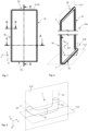
- Fig.1 shows an embodiment of a sealing element 2.
- the sealing element 2 can be mounted or integrated, for example, on or in a flat structural element of a locking device (not shown), in particular on a door leaf.
- the sealing element 2 has four sealing sections 3a to 3d, which form a continuous sealing element 4 in the form of a circumferential frame element 8 and can be arranged along two side edges, a bottom edge and an upper edge of the structural element.
- the sealing element 2 lies on the one hand in a plane XY, which is also spanned by the flat structural element.
- the plane XY is in Fig.2 shown.
- Fig.2 shows an isometric view of the sealing element 2 from Fig.1 It can be seen that parts of the sealing element 2 lie in a further plane YZ, which is spanned orthogonally to the plane XY. It is clear that the first sealing section 3a does not lie in the plane XY, which is spanned by the second, third and fourth sealing sections 3b, 3c, 3d.
- the surrounding frame element 8 is therefore L-shaped, with a first section 14a of the L-shape lying in the XY plane and a second section 14b of the L-shape lying in the YZ plane.
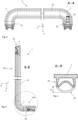
- Fig.3 shows a schematic isometric view of a deflection section 7, which is shown in a connection between the first sealing section 3a and the third sealing section 3c, for example for a sealing element 2 according to Fig.2 .
- the deflection section 7 has a possible double-curved shape, with a first curved section 7a and a second curved section 7b each being arranged in a different plane, each of which runs substantially transversely to the plane of the structural element.
- the two sections 7a, 7b are arranged one behind the other along a length of the deflection section 7.
- the first section 7a is designed as an angled section which is arranged in a plane XZ substantially transversely to the plane of the structural element.
- the second section 7b is also designed as an angled section which is arranged in a plane YZ substantially parallel to a plane of the floor.
- the orientation substantially transversely or substantially parallel to the respective plane is shown as an orientation transversely or parallel without possible manufacturing tolerances.
- the structural element is arranged in a plane XY and is not shown for reasons of clarity.
- a seal can be formed over the entire length of the deflection section 7, wherein the deflection section 7 can be sealingly contacted at least in sections with the frame element in the direction Z transverse to the structural element and/or at least in sections with a base in the direction X.
- the deflection cut is therefore preferably formed in sections along the base edge and in sections along a side edge of the structural element.
- the deflection section 7 is only shown schematically, wherein the seal in the deflection section 7 can have any cross-section. In particular, the deflection section 7 is formed in one piece.
- Fig.4 shows a sectional view along the plane AA from Fig.1 .
- the sealing element is not designed for the cross-sectional shape shown limited. It can be seen that the sealing element 2 is aligned in the direction Z at the second and third sealing sections 3b, 3c. Consequently, a seal with a frame element of the closure device (not shown) in the direction Z is possible with the second and third sealing sections 3b, 3c.
- a connection element 16 for supplying pressure medium is provided on the sealing element 2, which in this embodiment is connected to the sealing element 2 at the second sealing section 3b.
- Fig.5 shows a sectional view along the plane BB from Fig.1 .
- an L-shape of the sealing element 2 can be seen, with the fourth sealing section 3d being oriented in the Z direction and the first sealing section 3a being oriented in the X direction.
- the first sealing section 3a is arranged offset in parallel with respect to the plane XY, which is formed by the second and third sealing sections 3b, 3c.
- a distance in the Z direction between the second or third sealing sections 3b, 3c and the first sealing section 3a is determined by the geometry or shape of the deflection section 7.
- the deflection section 7 is designed as a type of angle element that is arranged in the XZ plane.
- a first leg of the angle element is oriented in the -X direction and a second leg in the -Z direction. Consequently, the first section 14a of the sealing element 2 is arranged at an angle to the second section 14a of the sealing element 2.
- Fig.6 shows a sectional view along the plane DD from Fig.1 .
- the sealing element 2 is made, for example, from silicone or a rubber material.
- the sealing element 2 In an unfilled state 19, the sealing element 2 has a smaller volume than in a filled state 20.
- the flat structural element 12 can be sealed with the frame element 11, for example shown in Fig.7
- a stroke 21 of preferably up to 10 mm can be formed so that a gap between the flat structural element 12 and the frame element 11 is sealed.
- the direction in which the stroke 21 is carried out corresponds to the direction in which the respective sealing section 3a to 3d is aligned.
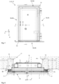
- Fig.7 shows an embodiment of a locking device 10 with a frame element 11 and a flat structural element 12.
- the locking device 10 is shown in the closed position 17 and can be, for example, an object protection door 1.
- Fig.8 shows a sectional view through the side edges of the structural element 12 along the plane AA from Fig.7 .
- the sealing element 2 can be arranged at any point in the flat structural element 12. For example, it can be arranged between an inner shell and an outer shell.
- the second sealing section 3b and the third sealing section 3c can be sealingly contacted with the frame element 11 in the direction Z, so that a gap in the region of the fold between the flat structural element 12 and the frame element 11 can be closed.
- Fig.9 shows a sectional view through the bottom edge and through the top edge along the plane BB from Fig.7 . It can be seen that the sealing element 2 in the first sealing section 3a is deflected in such a way that it can be sealingly contacted with the base 13 in the direction X.
- the sealing element 2 is aligned in the direction Z as in the second and third sealing sections 3b, 3c. It would also be conceivable that in the fourth sealing section 3d, the sealing element 2 is aligned against the direction X in order to seal a gap in the area of the fold.
- Fig.10 shows a sectional view along the plane BB from Fig.7 . This corresponds to a view according to Fig.5 , where Fig.10 the sealing element 2 is integrated in the flat structural element 12, in particular in the door leaf.
- the sealing element 2 is shown in the unfilled position 19 and in the filled position 20.
- the sealing element 2 In the unfilled position 19, the sealing element 2 is arranged at a distance from a counter surface 18, which forms an upper edge of the base 13.
- the sealing element 2 contacts the counter surface 18, so that a gap between the flat structural element 12 and the base 13 is sealed at the base edge of the structural element 12.
- Fig. 11 shows another possible section along the plane EE from Fig.2 .
- the fillable sealing element 2 is shown with a possible cross-sectional shape as a detailed sectional view.
- the sealing element is aligned on the sealing section 3a in the direction of the base 13, so that the sealing element 2 in the first sealing section 3a can be sealingly contacted with the base 13 in the direction X.
- the first sealing section 3a is connected to the third sealing section 3c via a deflection section 7.
- the deflection section 7 and the third sealing section 3c are not shown in the sectional view in this illustration.
- the dashed lines therefore show that the sealing element 2 is designed as an arc element, in particular as a doubly curved deflection section, along the deflection section 7 up to the third sealing section 3c. This enables the sealing element 2 to be guided from the YZ plane into the XY plane.
- the first sealing section 3a can be arranged at any distance from the second and third sealing sections 3b, 3c.
- the shape of the sealing element 2 is not limited to the shape shown.
- the fillable sealing element 2 can be formed by any hollow cross-section that is capable of enabling a stroke 21, in particular aligned in only one direction.
- the sealing element 2 is L-shaped as in Fig.5 is formed, however, the second and third sealing sections 3b, 3c can be aligned at any angle with respect to the plane XZ.
- the sealing element 2 in the second and third sealing sections 3b, 3b can be aligned in a direction inclined to the direction Z, in particular at an angle between 0° and 45°, preferably between 10° and 20°. Consequently, the sealing element 2 in at least the second and third sealing sections 3b, 3c can be sealed with a surface of a frame element which is formed inclined. The same applies in particular to the fourth sealing section 3d with respect to a direction Y.
Landscapes
- Engineering & Computer Science (AREA)
- Civil Engineering (AREA)
- Structural Engineering (AREA)
- Specific Sealing Or Ventilating Devices For Doors And Windows (AREA)
Claims (14)
- Dispositif de fermeture (10) pour l'étanchéification d'ouvertures de bâtiments ou de pièces, en particulier porte de protection de bâtiment (1),avec un élément structurel plat (12), en particulier un panneau de porte,avec un élément d'étanchéité remplissable (2), qui est relié à l'élément structurel plat (12), l'élément d'étanchéité remplissable (2) présentant au moins trois sections d'étanchéité (3a, 3b, 3c) contiguës,une première section d'étanchéité (3a) étant orientée le long d'un bord inférieur sensiblement parallèlement à un plan de l'élément structurel plat (12), de sorte que la première section d'étanchéité (3a) peut être mise en contact étanche avec un sol (13) dans une position fermée (17) du dispositif de fermeture (10),une deuxième section d'étanchéité (3b) et une troisième section d'étanchéité (3c) étant orientées chacune le long d'un bord latéral et sensiblement parallèlement à un plan de l'élément structurel plat, de sorte que la deuxième section d'étanchéité (3b) et la troisième section d'étanchéité (3c), dans la position fermée (17), peuvent être mises en contact étanche avec un élément de cadre (11), en particulier un châssis de porte, chacune dans une même direction sensiblement transversale au plan (X-Y) de l'élément structurel plat (12),caractérisé en ceque la première section d'étanchéité (3a) est décalée parallèlement par rapport à un plan (X-Y) qui passe par la deuxième et la troisième section d'étanchéité (3b, 3c).
- Dispositif de fermeture (10) selon la revendication 1,
caractérisé en ce
que la première section d'étanchéité (3a) est disposée entre la deuxième et la troisième section d'étanchéité (3b, 3c) . - Dispositif de fermeture (10) selon la revendication 1 ou 2,
caractérisé en ce
que l'élément d'étanchéité (2) présente une quatrième section d'étanchéité (3d) qui est reliée à la deuxième et à la troisième section d'étanchéité (3b, 3c) et qui est orientée le long d'un bord supérieur de l'élément structurel (12), de sorte qu'il est formé un élément d'étanchéité continu (4) qui est disposé de manière périphérique autour de l'élément structurel (12). - Dispositif de fermeture (10) selon la revendication 3,
caractérisé en ce
que la quatrième section d'étanchéité (3d) peut être mise en contact étanche avec l'élément de cadre (11) dans une direction sensiblement transversale au plan (X-Y) de l'élément structurel plat (12) ou dans une direction parallèle à un plan (X-Y) de l'élément structurel plat (12) . - Dispositif de fermeture (10) selon l'une des revendications précédentes,
caractérisé en ce
que la première section d'étanchéité (3a) est reliée à la deuxième section d'étanchéité (3b) et à la troisième section d'étanchéité (3c) par l'intermédiaire d'une section de renvoi respective (7), la section de renvoi (7) étant conçue comme une section d'étanchéité. - Dispositif de fermeture (10) selon la revendication 5,
caractérisé en ce
que la section de renvoi (7) permet une liaison de l'élément d'étanchéité (2) entre le plan (X-Y) parallèle à l'élément structurel plat (12) et un plan (Y-Z) transversal à l'élément structurel plat (12). - Dispositif de fermeture (10) selon la revendication 5 ou 6,
caractérisé en ce
que la section de renvoi (7) présente une forme doublement incurvée, une première partie incurvée (7a) et une deuxième partie incurvée (7b) étant respectivement disposées dans des plans différents qui sont chacun sensiblement transversaux au plan de l'élément structurel (12). - Dispositif de fermeture (10) selon l'une des revendications 5 à 7,
caractérisé en ce
qu'une d'étanchéité peut être réalisée sur une longueur complète de la section de renvoi (7), en particulier par remplissage du joint, la section de renvoi (7) pouvant être mise en contact étanche au moins par sections avec l'élément de cadre (11) dans la direction (Z) transversale à l'élément structurel plat (12) et/ou au moins par sections avec un sol (13), en particulier dans la direction (Y) parallèle à l'élément structurel plat (12). - Dispositif de fermeture (10) selon l'une des revendications précédentes,
caractérisé en ce
qu'une première section (14a) de l'élément d'étanchéité (3) est disposée de manière coudée par rapport à une deuxième section (14b) de l'élément d'étanchéité (3), la première section (14a) comprenant en particulier la deuxième et la troisième section d'étanchéité (3b, 3c) et la deuxième section (14b) comprenant la première section d'étanchéité (3a) . - Dispositif de fermeture (10) selon l'une des revendications précédentes,
caractérisé en ce
que l'élément d'étanchéité (2) est un élément d'étanchéité pouvant être mis en œuvre pneumatiquement. - Dispositif de fermeture (10) selon l'une des revendications précédentes,
caractérisé en ce
que l'élément d'étanchéité (2) est extensible par remplissage, l'élément d'étanchéité (2) présentant un volume plus faible dans une position non remplie (19) que dans une position remplie (20). - Dispositif de fermeture (10) selon l'une des revendications précédentes,
caractérisé en ce
qu'un élément de raccordement (16), qui est relié à l'élément d'étanchéité (2), est prévu pour l'amenée d'un fluide sous pression. - Dispositif de fermeture (10) selon l'une des revendications précédentes,
caractérisé en ce
qu'un cadre d'étanchéité (5) est prévu pour recevoir et guider l'élément d'étanchéité (2). - Dispositif de fermeture (10) selon la revendication 13,
caractérisé en ce
que le cadre d'étanchéité (5) présente au moins trois, en particulier quatre, sections de cadre d'étanchéité (6a, 6b, 6c, 6d), chaque section de cadre d'étanchéité (6a, 6b, 6c, 6d) étant conçue pour recevoir et guider une section d'étanchéité (3a, 3b, 3c, 3d).
Applications Claiming Priority (1)
| Application Number | Priority Date | Filing Date | Title |
|---|---|---|---|
| DE102021003006.0A DE102021003006A1 (de) | 2021-06-11 | 2021-06-11 | Verschlussvorrichtung zur Abdichtung von Gebäudeöffnungen oder Räumen |
Publications (2)
| Publication Number | Publication Date |
|---|---|
| EP4108880A1 EP4108880A1 (fr) | 2022-12-28 |
| EP4108880B1 true EP4108880B1 (fr) | 2024-05-29 |
Family
ID=81653529
Family Applications (1)
| Application Number | Title | Priority Date | Filing Date |
|---|---|---|---|
| EP22173240.7A Active EP4108880B1 (fr) | 2021-06-11 | 2022-05-13 | Dispositif de fermeture destiné à l'étanchéité des ouvertures ou des espaces de bâtiment |
Country Status (2)
| Country | Link |
|---|---|
| EP (1) | EP4108880B1 (fr) |
| DE (1) | DE102021003006A1 (fr) |
Family Cites Families (5)
| Publication number | Priority date | Publication date | Assignee | Title |
|---|---|---|---|---|
| DE2851459C2 (de) | 1978-11-28 | 1980-11-27 | Metall + Plastic Gmbh, 7760 Radolfzell | Gasdicht schließende Tür |
| NL8204689A (nl) * | 1982-12-03 | 1984-07-02 | Cornelis Petrus Sijm | Deur ter afsluiting van opslagruimten voor aan bederf onderhevige produkten. |
| US4706413A (en) | 1986-10-16 | 1987-11-17 | James Kenneth S | Smoke detector-activated door seal |
| CA1272417A (fr) * | 1986-11-27 | 1990-08-07 | Leonard William Westwell | Porte etanche a l'air |
| DE202013103304U1 (de) * | 2013-06-27 | 2014-09-29 | Manfred Schmid | System zum wasserdichten Verschließen einer Gebäudeöffnung |
-
2021
- 2021-06-11 DE DE102021003006.0A patent/DE102021003006A1/de not_active Withdrawn
-
2022
- 2022-05-13 EP EP22173240.7A patent/EP4108880B1/fr active Active
Also Published As
| Publication number | Publication date |
|---|---|
| DE102021003006A1 (de) | 2022-12-15 |
| EP4108880A1 (fr) | 2022-12-28 |
Similar Documents
| Publication | Publication Date | Title |
|---|---|---|
| EP2941798B1 (fr) | Boîtier de connecteur enfichable étanche au milieu ambiant | |
| EP3752763B1 (fr) | Manchette d'étanchéité pour être introduite dans un système de canalisations | |
| EP2479469B1 (fr) | Ensemble raccord et procédé de fabrication d'un tel ensemble raccord | |
| EP0627582A1 (fr) | Dispositif de joint | |
| DE2831029A1 (de) | Gehaeuse zum schutz der verbindungsstelle von langgestreckten gegenstaenden, insbesondere zum schutz eines kabelspleisses | |
| DE69936554T2 (de) | Eckpfosten für Schaltschrank und damit ausgerüsteter Schaltschrank | |
| DE1912905B2 (de) | Korrosionsbeständiger Kegelhahn | |
| EP4108880B1 (fr) | Dispositif de fermeture destiné à l'étanchéité des ouvertures ou des espaces de bâtiment | |
| EP0135042B1 (fr) | Dispositif de vanne à tiroir | |
| EP2962017A1 (fr) | Joint plat pour raccords à brides | |
| DE102016106934A1 (de) | Dichtung und Fensterelement | |
| DE102014001726A1 (de) | Schieberventil | |
| DE102013015895B4 (de) | Pressfitting und Verbindungsanordnung mit einem solchen Pressfitting | |
| EP2657583A1 (fr) | Armature d'arrêt triplement excentrique | |
| DE102020127493A1 (de) | Ventil mit Ventilkörper | |
| DE4114902A1 (de) | Absperrvorrichtung | |
| DE10333365A1 (de) | Dichtung mit variablem Innendurchmesser | |
| DE3002140A1 (de) | Kunststoffdichtring | |
| DE3812976A1 (de) | Flachdichtung | |
| EP1507996A1 (fr) | Collier d'attache pour tuyaux | |
| DE8432321U1 (de) | Abdichtungsvorrichtung für Rohrleitungen, die in einem Futterrohr geführt sind | |
| DE2135514C3 (de) | Rohrmuffe für winkelbewegliche Rohrleitungen | |
| EP3842671B1 (fr) | Joint d'étanchéité d'arbre, en particulier joint d'étanchéité d'arbre radial, pourvu d'au moins un élément d'étanchéité | |
| WO2013159838A1 (fr) | Joint à cadre support à encombrement réduit | |
| EP1645792B1 (fr) | Dispositif de perçage |
Legal Events
| Date | Code | Title | Description |
|---|---|---|---|
| PUAI | Public reference made under article 153(3) epc to a published international application that has entered the european phase |
Free format text: ORIGINAL CODE: 0009012 |
|
| STAA | Information on the status of an ep patent application or granted ep patent |
Free format text: STATUS: THE APPLICATION HAS BEEN PUBLISHED |
|
| AK | Designated contracting states |
Kind code of ref document: A1 Designated state(s): AL AT BE BG CH CY CZ DE DK EE ES FI FR GB GR HR HU IE IS IT LI LT LU LV MC MK MT NL NO PL PT RO RS SE SI SK SM TR |
|
| STAA | Information on the status of an ep patent application or granted ep patent |
Free format text: STATUS: REQUEST FOR EXAMINATION WAS MADE |
|
| 17P | Request for examination filed |
Effective date: 20230309 |
|
| RBV | Designated contracting states (corrected) |
Designated state(s): AL AT BE BG CH CY CZ DE DK EE ES FI FR GB GR HR HU IE IS IT LI LT LU LV MC MK MT NL NO PL PT RO RS SE SI SK SM TR |
|
| P01 | Opt-out of the competence of the unified patent court (upc) registered |
Effective date: 20230419 |
|
| GRAP | Despatch of communication of intention to grant a patent |
Free format text: ORIGINAL CODE: EPIDOSNIGR1 |
|
| STAA | Information on the status of an ep patent application or granted ep patent |
Free format text: STATUS: GRANT OF PATENT IS INTENDED |
|
| INTG | Intention to grant announced |
Effective date: 20240119 |
|
| GRAS | Grant fee paid |
Free format text: ORIGINAL CODE: EPIDOSNIGR3 |
|
| GRAA | (expected) grant |
Free format text: ORIGINAL CODE: 0009210 |
|
| STAA | Information on the status of an ep patent application or granted ep patent |
Free format text: STATUS: THE PATENT HAS BEEN GRANTED |
|
| AK | Designated contracting states |
Kind code of ref document: B1 Designated state(s): AL AT BE BG CH CY CZ DE DK EE ES FI FR GB GR HR HU IE IS IT LI LT LU LV MC MK MT NL NO PL PT RO RS SE SI SK SM TR |
|
| REG | Reference to a national code |
Ref country code: CH Ref legal event code: EP |
|
| REG | Reference to a national code |
Ref country code: IE Ref legal event code: FG4D Free format text: LANGUAGE OF EP DOCUMENT: GERMAN |
|
| REG | Reference to a national code |
Ref country code: DE Ref legal event code: R096 Ref document number: 502022000951 Country of ref document: DE |
|
| REG | Reference to a national code |
Ref country code: LT Ref legal event code: MG9D |
|
| REG | Reference to a national code |
Ref country code: NL Ref legal event code: MP Effective date: 20240529 |
|
| PG25 | Lapsed in a contracting state [announced via postgrant information from national office to epo] |
Ref country code: IS Free format text: LAPSE BECAUSE OF FAILURE TO SUBMIT A TRANSLATION OF THE DESCRIPTION OR TO PAY THE FEE WITHIN THE PRESCRIBED TIME-LIMIT Effective date: 20240929 |
|
| PG25 | Lapsed in a contracting state [announced via postgrant information from national office to epo] |
Ref country code: BG Free format text: LAPSE BECAUSE OF FAILURE TO SUBMIT A TRANSLATION OF THE DESCRIPTION OR TO PAY THE FEE WITHIN THE PRESCRIBED TIME-LIMIT Effective date: 20240529 |
|
| PG25 | Lapsed in a contracting state [announced via postgrant information from national office to epo] |
Ref country code: HR Free format text: LAPSE BECAUSE OF FAILURE TO SUBMIT A TRANSLATION OF THE DESCRIPTION OR TO PAY THE FEE WITHIN THE PRESCRIBED TIME-LIMIT Effective date: 20240529 Ref country code: FI Free format text: LAPSE BECAUSE OF FAILURE TO SUBMIT A TRANSLATION OF THE DESCRIPTION OR TO PAY THE FEE WITHIN THE PRESCRIBED TIME-LIMIT Effective date: 20240529 |
|
| PG25 | Lapsed in a contracting state [announced via postgrant information from national office to epo] |
Ref country code: GR Free format text: LAPSE BECAUSE OF FAILURE TO SUBMIT A TRANSLATION OF THE DESCRIPTION OR TO PAY THE FEE WITHIN THE PRESCRIBED TIME-LIMIT Effective date: 20240830 |
|
| PG25 | Lapsed in a contracting state [announced via postgrant information from national office to epo] |
Ref country code: ES Free format text: LAPSE BECAUSE OF FAILURE TO SUBMIT A TRANSLATION OF THE DESCRIPTION OR TO PAY THE FEE WITHIN THE PRESCRIBED TIME-LIMIT Effective date: 20240529 |
|
| PG25 | Lapsed in a contracting state [announced via postgrant information from national office to epo] |
Ref country code: PL Free format text: LAPSE BECAUSE OF FAILURE TO SUBMIT A TRANSLATION OF THE DESCRIPTION OR TO PAY THE FEE WITHIN THE PRESCRIBED TIME-LIMIT Effective date: 20240529 |
|
| PG25 | Lapsed in a contracting state [announced via postgrant information from national office to epo] |
Ref country code: LV Free format text: LAPSE BECAUSE OF FAILURE TO SUBMIT A TRANSLATION OF THE DESCRIPTION OR TO PAY THE FEE WITHIN THE PRESCRIBED TIME-LIMIT Effective date: 20240529 |
|
| PG25 | Lapsed in a contracting state [announced via postgrant information from national office to epo] |
Ref country code: PL Free format text: LAPSE BECAUSE OF FAILURE TO SUBMIT A TRANSLATION OF THE DESCRIPTION OR TO PAY THE FEE WITHIN THE PRESCRIBED TIME-LIMIT Effective date: 20240529 Ref country code: NO Free format text: LAPSE BECAUSE OF FAILURE TO SUBMIT A TRANSLATION OF THE DESCRIPTION OR TO PAY THE FEE WITHIN THE PRESCRIBED TIME-LIMIT Effective date: 20240829 Ref country code: LV Free format text: LAPSE BECAUSE OF FAILURE TO SUBMIT A TRANSLATION OF THE DESCRIPTION OR TO PAY THE FEE WITHIN THE PRESCRIBED TIME-LIMIT Effective date: 20240529 Ref country code: IS Free format text: LAPSE BECAUSE OF FAILURE TO SUBMIT A TRANSLATION OF THE DESCRIPTION OR TO PAY THE FEE WITHIN THE PRESCRIBED TIME-LIMIT Effective date: 20240929 Ref country code: HR Free format text: LAPSE BECAUSE OF FAILURE TO SUBMIT A TRANSLATION OF THE DESCRIPTION OR TO PAY THE FEE WITHIN THE PRESCRIBED TIME-LIMIT Effective date: 20240529 Ref country code: GR Free format text: LAPSE BECAUSE OF FAILURE TO SUBMIT A TRANSLATION OF THE DESCRIPTION OR TO PAY THE FEE WITHIN THE PRESCRIBED TIME-LIMIT Effective date: 20240830 Ref country code: FI Free format text: LAPSE BECAUSE OF FAILURE TO SUBMIT A TRANSLATION OF THE DESCRIPTION OR TO PAY THE FEE WITHIN THE PRESCRIBED TIME-LIMIT Effective date: 20240529 Ref country code: ES Free format text: LAPSE BECAUSE OF FAILURE TO SUBMIT A TRANSLATION OF THE DESCRIPTION OR TO PAY THE FEE WITHIN THE PRESCRIBED TIME-LIMIT Effective date: 20240529 Ref country code: BG Free format text: LAPSE BECAUSE OF FAILURE TO SUBMIT A TRANSLATION OF THE DESCRIPTION OR TO PAY THE FEE WITHIN THE PRESCRIBED TIME-LIMIT Effective date: 20240529 Ref country code: RS Free format text: LAPSE BECAUSE OF FAILURE TO SUBMIT A TRANSLATION OF THE DESCRIPTION OR TO PAY THE FEE WITHIN THE PRESCRIBED TIME-LIMIT Effective date: 20240829 |
|
| PG25 | Lapsed in a contracting state [announced via postgrant information from national office to epo] |
Ref country code: NL Free format text: LAPSE BECAUSE OF FAILURE TO SUBMIT A TRANSLATION OF THE DESCRIPTION OR TO PAY THE FEE WITHIN THE PRESCRIBED TIME-LIMIT Effective date: 20240529 |
|
| PG25 | Lapsed in a contracting state [announced via postgrant information from national office to epo] |
Ref country code: NL Free format text: LAPSE BECAUSE OF FAILURE TO SUBMIT A TRANSLATION OF THE DESCRIPTION OR TO PAY THE FEE WITHIN THE PRESCRIBED TIME-LIMIT Effective date: 20240529 |
|
| PG25 | Lapsed in a contracting state [announced via postgrant information from national office to epo] |
Ref country code: DK Free format text: LAPSE BECAUSE OF FAILURE TO SUBMIT A TRANSLATION OF THE DESCRIPTION OR TO PAY THE FEE WITHIN THE PRESCRIBED TIME-LIMIT Effective date: 20240529 |
|
| PG25 | Lapsed in a contracting state [announced via postgrant information from national office to epo] |
Ref country code: EE Free format text: LAPSE BECAUSE OF FAILURE TO SUBMIT A TRANSLATION OF THE DESCRIPTION OR TO PAY THE FEE WITHIN THE PRESCRIBED TIME-LIMIT Effective date: 20240529 |
|
| PG25 | Lapsed in a contracting state [announced via postgrant information from national office to epo] |
Ref country code: CZ Free format text: LAPSE BECAUSE OF FAILURE TO SUBMIT A TRANSLATION OF THE DESCRIPTION OR TO PAY THE FEE WITHIN THE PRESCRIBED TIME-LIMIT Effective date: 20240529 |
|
| PG25 | Lapsed in a contracting state [announced via postgrant information from national office to epo] |
Ref country code: SK Free format text: LAPSE BECAUSE OF FAILURE TO SUBMIT A TRANSLATION OF THE DESCRIPTION OR TO PAY THE FEE WITHIN THE PRESCRIBED TIME-LIMIT Effective date: 20240529 Ref country code: RO Free format text: LAPSE BECAUSE OF FAILURE TO SUBMIT A TRANSLATION OF THE DESCRIPTION OR TO PAY THE FEE WITHIN THE PRESCRIBED TIME-LIMIT Effective date: 20240529 |
|
| PG25 | Lapsed in a contracting state [announced via postgrant information from national office to epo] |
Ref country code: SM Free format text: LAPSE BECAUSE OF FAILURE TO SUBMIT A TRANSLATION OF THE DESCRIPTION OR TO PAY THE FEE WITHIN THE PRESCRIBED TIME-LIMIT Effective date: 20240529 |
|
| PG25 | Lapsed in a contracting state [announced via postgrant information from national office to epo] |
Ref country code: SM Free format text: LAPSE BECAUSE OF FAILURE TO SUBMIT A TRANSLATION OF THE DESCRIPTION OR TO PAY THE FEE WITHIN THE PRESCRIBED TIME-LIMIT Effective date: 20240529 Ref country code: SK Free format text: LAPSE BECAUSE OF FAILURE TO SUBMIT A TRANSLATION OF THE DESCRIPTION OR TO PAY THE FEE WITHIN THE PRESCRIBED TIME-LIMIT Effective date: 20240529 Ref country code: RO Free format text: LAPSE BECAUSE OF FAILURE TO SUBMIT A TRANSLATION OF THE DESCRIPTION OR TO PAY THE FEE WITHIN THE PRESCRIBED TIME-LIMIT Effective date: 20240529 Ref country code: EE Free format text: LAPSE BECAUSE OF FAILURE TO SUBMIT A TRANSLATION OF THE DESCRIPTION OR TO PAY THE FEE WITHIN THE PRESCRIBED TIME-LIMIT Effective date: 20240529 Ref country code: DK Free format text: LAPSE BECAUSE OF FAILURE TO SUBMIT A TRANSLATION OF THE DESCRIPTION OR TO PAY THE FEE WITHIN THE PRESCRIBED TIME-LIMIT Effective date: 20240529 Ref country code: CZ Free format text: LAPSE BECAUSE OF FAILURE TO SUBMIT A TRANSLATION OF THE DESCRIPTION OR TO PAY THE FEE WITHIN THE PRESCRIBED TIME-LIMIT Effective date: 20240529 |
|
| PG25 | Lapsed in a contracting state [announced via postgrant information from national office to epo] |
Ref country code: IT Free format text: LAPSE BECAUSE OF FAILURE TO SUBMIT A TRANSLATION OF THE DESCRIPTION OR TO PAY THE FEE WITHIN THE PRESCRIBED TIME-LIMIT Effective date: 20240529 |
|
| REG | Reference to a national code |
Ref country code: DE Ref legal event code: R097 Ref document number: 502022000951 Country of ref document: DE |
|
| PLBE | No opposition filed within time limit |
Free format text: ORIGINAL CODE: 0009261 |
|
| STAA | Information on the status of an ep patent application or granted ep patent |
Free format text: STATUS: NO OPPOSITION FILED WITHIN TIME LIMIT |
|
| PG25 | Lapsed in a contracting state [announced via postgrant information from national office to epo] |
Ref country code: SI Free format text: LAPSE BECAUSE OF FAILURE TO SUBMIT A TRANSLATION OF THE DESCRIPTION OR TO PAY THE FEE WITHIN THE PRESCRIBED TIME-LIMIT Effective date: 20240529 |
|
| 26N | No opposition filed |
Effective date: 20250303 |
|
| PGFP | Annual fee paid to national office [announced via postgrant information from national office to epo] |
Ref country code: DE Payment date: 20250528 Year of fee payment: 4 |
|
| PGFP | Annual fee paid to national office [announced via postgrant information from national office to epo] |
Ref country code: FR Payment date: 20250528 Year of fee payment: 4 |
|
| PGFP | Annual fee paid to national office [announced via postgrant information from national office to epo] |
Ref country code: AT Payment date: 20250721 Year of fee payment: 4 |
|
| PG25 | Lapsed in a contracting state [announced via postgrant information from national office to epo] |
Ref country code: SE Free format text: LAPSE BECAUSE OF FAILURE TO SUBMIT A TRANSLATION OF THE DESCRIPTION OR TO PAY THE FEE WITHIN THE PRESCRIBED TIME-LIMIT Effective date: 20240529 |
|
| REG | Reference to a national code |
Ref country code: CH Ref legal event code: H13 Free format text: ST27 STATUS EVENT CODE: U-0-0-H10-H13 (AS PROVIDED BY THE NATIONAL OFFICE) Effective date: 20251223 |
|
| PG25 | Lapsed in a contracting state [announced via postgrant information from national office to epo] |
Ref country code: LU Free format text: LAPSE BECAUSE OF NON-PAYMENT OF DUE FEES Effective date: 20250513 |
|
| PG25 | Lapsed in a contracting state [announced via postgrant information from national office to epo] |
Ref country code: CH Free format text: LAPSE BECAUSE OF NON-PAYMENT OF DUE FEES Effective date: 20250531 |
|
| REG | Reference to a national code |
Ref country code: BE Ref legal event code: MM Effective date: 20250531 |
|
| PG25 | Lapsed in a contracting state [announced via postgrant information from national office to epo] |
Ref country code: MC Free format text: LAPSE BECAUSE OF FAILURE TO SUBMIT A TRANSLATION OF THE DESCRIPTION OR TO PAY THE FEE WITHIN THE PRESCRIBED TIME-LIMIT Effective date: 20240529 |
|
| PG25 | Lapsed in a contracting state [announced via postgrant information from national office to epo] |
Ref country code: IE Free format text: LAPSE BECAUSE OF NON-PAYMENT OF DUE FEES Effective date: 20250513 |
|
| PG25 | Lapsed in a contracting state [announced via postgrant information from national office to epo] |
Ref country code: BE Free format text: LAPSE BECAUSE OF NON-PAYMENT OF DUE FEES Effective date: 20250531 |