EP4108917A1 - Vorrichtung und verfahren zur steuerung des drucks eines fluids in einem mechanisch gepumpten zweiphasigen fluidkreislauf - Google Patents
Vorrichtung und verfahren zur steuerung des drucks eines fluids in einem mechanisch gepumpten zweiphasigen fluidkreislauf Download PDFInfo
- Publication number
- EP4108917A1 EP4108917A1 EP22180651.6A EP22180651A EP4108917A1 EP 4108917 A1 EP4108917 A1 EP 4108917A1 EP 22180651 A EP22180651 A EP 22180651A EP 4108917 A1 EP4108917 A1 EP 4108917A1
- Authority
- EP
- European Patent Office
- Prior art keywords
- fluid
- pressure
- temperature
- closed circuit
- evaporator
- Prior art date
- Legal status (The legal status is an assumption and is not a legal conclusion. Google has not performed a legal analysis and makes no representation as to the accuracy of the status listed.)
- Granted
Links
Images


Classifications
-
- F—MECHANICAL ENGINEERING; LIGHTING; HEATING; WEAPONS; BLASTING
- F04—POSITIVE - DISPLACEMENT MACHINES FOR LIQUIDS; PUMPS FOR LIQUIDS OR ELASTIC FLUIDS
- F04B—POSITIVE-DISPLACEMENT MACHINES FOR LIQUIDS; PUMPS
- F04B15/00—Pumps adapted to handle specific fluids, e.g. by selection of specific materials for pumps or pump parts
- F04B15/06—Pumps adapted to handle specific fluids, e.g. by selection of specific materials for pumps or pump parts for liquids near their boiling point, e.g. under subnormal pressure
-
- F—MECHANICAL ENGINEERING; LIGHTING; HEATING; WEAPONS; BLASTING
- F04—POSITIVE - DISPLACEMENT MACHINES FOR LIQUIDS; PUMPS FOR LIQUIDS OR ELASTIC FLUIDS
- F04B—POSITIVE-DISPLACEMENT MACHINES FOR LIQUIDS; PUMPS
- F04B49/00—Control, e.g. of pump delivery, or pump pressure of, or safety measures for, machines, pumps, or pumping installations, not otherwise provided for, or of interest apart from, groups F04B1/00 - F04B47/00
- F04B49/06—Control using electricity
- F04B49/065—Control using electricity and making use of computers
-
- F—MECHANICAL ENGINEERING; LIGHTING; HEATING; WEAPONS; BLASTING
- F25—REFRIGERATION OR COOLING; COMBINED HEATING AND REFRIGERATION SYSTEMS; HEAT PUMP SYSTEMS; MANUFACTURE OR STORAGE OF ICE; LIQUEFACTION SOLIDIFICATION OF GASES
- F25B—REFRIGERATION MACHINES, PLANTS OR SYSTEMS; COMBINED HEATING AND REFRIGERATION SYSTEMS; HEAT PUMP SYSTEMS
- F25B23/00—Machines, plants or systems, with a single mode of operation not covered by groups F25B1/00 - F25B21/00, e.g. using selective radiation effect
- F25B23/006—Machines, plants or systems, with a single mode of operation not covered by groups F25B1/00 - F25B21/00, e.g. using selective radiation effect boiling cooling systems
-
- F—MECHANICAL ENGINEERING; LIGHTING; HEATING; WEAPONS; BLASTING
- F28—HEAT EXCHANGE IN GENERAL
- F28D—HEAT-EXCHANGE APPARATUS, NOT PROVIDED FOR IN ANOTHER SUBCLASS, IN WHICH THE HEAT-EXCHANGE MEDIA DO NOT COME INTO DIRECT CONTACT
- F28D15/00—Heat-exchange apparatus with the intermediate heat-transfer medium in closed tubes passing into or through the conduit walls ; Heat-exchange apparatus employing intermediate heat-transfer medium or bodies
- F28D15/02—Heat-exchange apparatus with the intermediate heat-transfer medium in closed tubes passing into or through the conduit walls ; Heat-exchange apparatus employing intermediate heat-transfer medium or bodies in which the medium condenses and evaporates, e.g. heat pipes
Definitions
- the present invention is in the field of thermal control of sets of dissipative equipment.
- the invention relates to a device and method for controlling the pressure of a fluid in a two-phase fluid loop with mechanical pumping. It is described in the field of spacecraft of the satellite type but it applies to any two-phase fluid loop system with mechanical pumping.
- a two-phase fluid loop with mechanical pumping comprises a closed circuit in which a heat transfer fluid circulates, an evaporator, through which the fluid circulates and evaporates to a partially gaseous state (called two-phase) under the effect of the energy provided by the dissipative equipment, a condenser, through which the fluid in partially gaseous form circulates at the inlet is transformed into liquid fluid, a pump, placed between the outlet of the condenser and the inlet of the evaporator, intended to moving the fluid in the closed circuit from the evaporator to the condenser in partially gaseous form and from the condenser to the evaporator in liquid form, a fluid reservoir connected to the closed circuit, intended to compensate for variations in fluid volume in the closed circuit.
- saturation defines a condition in which a mixture of vapor and liquid can exist together at a given temperature and pressure.
- the temperature at which vaporization (boiling) begins to occur for a given pressure is called the saturation temperature or boiling point.
- the pressure at which vaporization (boiling) begins to occur for a given temperature is called the saturation pressure.
- the saturation pressure When the vapor quality is 0, it is called a saturated liquid state.
- the vapor quality is equal to 1, it is called a saturated vapor state.
- Subcooling is the difference between the temperature of the liquid fluid and the saturation temperature (set by the pressure).
- the need is to control such a two-phase fluid loop in order to respect certain operational constraints of the installed dissipative equipment and of the constituent subsystems of the loop.
- one of the critical components of a mechanically pumped loop is its pump.
- the pump In order to guarantee its correct operation over the lifetime of the satellite, the pump must operate with a liquid fluid only (without NCG -non-condensable gases- and NH3 vapour) and with a level of sub-cooling high enough to eliminate any risk of cavitation.
- the critical parameter is the minimum subcooling.
- Dissipative equipment also has certain operational constraints, a maximum temperature but also a limitation on the thermal cycles that it undergoes (in number and amplitude) in order to limit the fatigue phenomena of its constituents.
- the control of the pressure in the fluid loop is carried out by a very simple control which consists in fixing a pressure level of the loop at a maximum value constrained by the temperature limit of the dissipative equipment installed on the satellite.
- the fluid loop is either single-phase or two-phase.
- the faults are as follows.
- the flow must be very high to carry all the power without reaching saturation of the fluid and remain within a compatible temperature range of the satellite equipment.
- the mass of such a loop is therefore much higher.
- such a solution has strong temperature inhomogeneities along the exchangers since the energy of the dissipative equipment is stored in the form of a temperature difference.
- this method in no way guarantees the minimum of subcooling at the level of the pump, a destructive phenomenon for the subsystem.
- This solution also does not guarantee a limited temperature variation at the dissipative equipment level, to avoid temperature cycling problems.
- the invention aims to overcome all or part of the problems mentioned above by proposing control of a two-phase fluid loop with mechanical pumping, in particular for a space application.
- Control laws make it possible to dynamically regulate the pressure within the loop in order to adjust the saturation temperature to limit the intensity of its variations over time or the difference between the saturation temperature and the liquid temperature (the subcooling).
- the invention proposes in particular a control of the loop with mechanical pumping to guarantee the conditions of fluid only liquid at the level of the pump (or any other equipment requiring a minimum of subcooling), with a level of subcooling sufficiently high to eliminate any risk of cavitation.
- the device for measuring the temperature of the fluid in liquid form is a temperature sensor immersed in the closed circuit or arranged on an outer wall of the closed circuit.
- the device for measuring the pressure of the fluid at a point of the closed circuit is a pressure sensor placed in the closed circuit or a temperature sensor of the fluid in partially gaseous form placed in the closed circuit between the outlet of the evaporator and the condenser inlet or a temperature sensor disposed on the reservoir.
- the device for adjusting the pressure in the closed circuit is a mechanical pressure control device or a device for heating the fluid in the reservoir.
- the step of adjusting the pressure is carried out by heating the fluid, or by mechanical action, in the reservoir, so as to control a difference between the measured temperature value of the fluid in liquid form and a measured temperature value fluid in the reservoir.
- the pressure adjustment step is carried out if a difference between the measured value of the saturation temperature and a maximum value of the previously defined saturation temperature is greater than a previously defined threshold value.
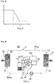
- the figure 1 schematically represents a device 10 for controlling the pressure of a heat transfer fluid in a two-phase fluid loop with mechanical pumping according to the invention.
- the two-phase fluid loop with mechanical pumping comprises a closed circuit 11 in which circulates a heat transfer fluid 20.
- the loop comprises at least one evaporator 12 comprising an inlet 13 and an outlet 14, through which the fluid circulates from the inlet 13 of the evaporator 12 in liquid form 20-liq to the outlet 14 of the evaporator 12, the evaporator 12 being configured to transform the fluid in liquid form 20-liq into fluid in partially gaseous form 20-g.
- the evaporator is configured to recover, to capture a certain quantity of thermal energy external to the loop, in particular coming from the dissipative equipment on the satellite.
- the loop comprises at least one condenser 15 comprising an inlet 16 and an outlet 17, through which the fluid in partially gaseous form 20-g circulates from the inlet 16 of the condenser 15 to the outlet 17 of the condenser 15, the condenser 15 being configured to convert 20-g partially gaseous fluid to 20-liq liquid fluid.
- the condenser is configured to restore a certain amount of thermal energy to the outside of the loop, for example to the cold space around the satellite.
- the loop comprises a pump 18, arranged between the outlet 17 of the condenser 15 and the inlet 13 of the evaporator 12, intended to move the fluid in the closed circuit 11 from the evaporator 12 to the condenser 15 in partially gaseous 20-g, and from the condenser 15 to the evaporator 12 in liquid form 20-liq.
- the loop comprises a fluid reservoir 19 connected to the closed circuit 11, intended to compensate for the variations in volume of fluid in the closed circuit 11, in connection with the quantity of vapor, due to evaporation, present in the closed circuit .
- the control device 10 comprises a device 21 for measuring the temperature of the fluid in liquid form 20-liq capable of providing a measured value 22 of the temperature of the fluid in liquid form, a device for measuring the pressure of the fluid at a point of the closed circuit 11 able to supply a measured value 24 of the pressure of the fluid, a device 25 for adjusting the pressure in the closed circuit 11, a means 26 for controlling the device 25 for adjusting the pressure as a function of the measured fluid pressure value 24 and of a pressure setpoint value Pcons, said pressure setpoint value Pcons being variable according to the measured values 22 and 24 respectively of the temperature of the fluid in liquid form 20-liq and pressure in the loop.
- the device according to the invention thus allows dynamic regulation of the pressure within the loop in order to adjust the difference between the saturation temperature (a function of the internal pressure in the loop) and the temperature of the fluid in liquid form upstream of the pump.
- the device 25 for adjusting the pressure in the closed circuit 11 is activated according to the value 24 of the measured pressure of the fluid and a setpoint value Pcons, and the setpoint value Pcons of the pressure (target) n' is not a fixed value but depends on the value 22 of the temperature of the fluid in liquid form 20-liq.
- the figure 2 schematically represents an embodiment of a device 50 for controlling the pressure of a fluid in a two-phase fluid loop with mechanical pumping according to the invention.
- the control device 50 comprises a device 28 for measuring the temperature of the fluid in the reservoir 19, capable of providing a measured value 29 of the temperature of the fluid in the reservoir 19, and a device 30 for heating the fluid in the reservoir 19.
- the temperature of the reservoir 19 is directly linked to the saturation temperature, itself linked to the pressure in the circuit 11.
- the means of servo 26 is configured to activate the device for heating the fluid in the tank 19, so as to control a difference between the measured value 22 of the temperature of the fluid in liquid form 20-liq and the measured value 29 of the temperature of the fluid in the reservoir 19.
- This embodiment makes it possible to control the temperature difference between the temperature of the fluid and the temperature of the reservoir.
- the picture 3 represents a sub-cooling control law (axis of ordinates) as a function of the temperature of the liquid fluid (axis of abscissas) according to the invention.
- Subcooling quantifies a difference between the saturation temperature and the temperature of the fluid.
- a subcooling level (level a) is assigned.
- the fluid used is ammonia.
- NCG non-condensable gases
- the choice of ⁇ and ⁇ levels is based on the subcooling required to remove the risk of cavitation at the level of the pump and or other sensitive components, as well as on the volume of the loop, the quantity of NCG estimated in the loop, the temperature operating range.
- the curve represented on the picture 3 is an example of a curve for the subcooling law. This curve is determined experimentally on the basis of a plurality of temperature measurements and corresponds to a given heat transfer fluid and a given set of equipment.
- Sub-cooling is controlled by heating the fluid in the reservoir to control the difference between the temperature of the fluid in the reservoir and therefore the pressure and the saturation level in the loop and the temperature of the fluid in liquid form, c i.e. the temperature difference between the pump inlet and the reservoir.
- the figure 4 schematically represents another embodiment of a device 60 for controlling the pressure of a fluid in a two-phase fluid loop with mechanical pumping according to the invention.
- the control device 60 further comprises a calculator 40 of a difference 41 between the measured value 24 of the pressure in the circuit 11 at a time t and a maximum value 42 of the pressure in the circuit 11 measured over a predefined period.
- the servo-control means 26 is configured to activate the device 25 for adjusting the pressure in the closed circuit 11 if the difference 41 is greater than a threshold value 43 previously defined.
- This embodiment makes it possible to trigger a pressurization of the fluid in the closed circuit 11 to limit the variation of the saturation temperature. This whole process of control can be done based on saturation temperatures instead of pressures.
- the objective is to limit the height of variation of the saturation temperature over a defined period to limit thermal cycling of dissipative equipment.
- the figure 5 represents the evolution of the saturation temperature (ordinate axis) as a function of time (abscissa axis) at a point of the two-phase fluid loop, without (left part of the figure) and with (right part of the figure) a control of the variation in temperature over time according to the invention.
- the temperature of the equipment is closely linked to the saturation temperature (fixed by the pressure) in the loop.
- the variations in the environment of the satellite generate variations in saturation temperature and therefore in temperature at the level of the dissipative equipment. These variations can cause fatigue problems due to the many cycles over the lifetime of the satellite. This phenomenon is represented on the curve to the left of the figure 5 . Without control of the variation in temperature over time, it can be seen that the saturation temperature oscillates between a maximum value 42 and minimum values. In this case, the difference 44 between the saturation temperature and the maximum value can be very large.
- the innovative solution of the invention is a law which limits the variation of the saturation temperature over a given period. For example, over a certain period, the maximum temperature of the fluid in the tank is observed. This is how the maximum value 42 can be determined.
- a threshold value 43 between the measured value 29 of the temperature of the fluid in the reservoir (saturation temperature) and the maximum value 42 is defined.
- the threshold value 43 is chosen according to the fatigue stresses of the dissipative equipment. The sliding duration over which this check is carried out depends on the type of satellite in its orbit and on the dissipative equipment to be checked.
- the control device 60 is configured to observe at regular intervals the temperature of the current reservoir 29 and determine whether the current difference 41 between the temperature of the current reservoir 29 and the temperature maximum 42 is lower than the threshold value 43. If it is lower, this means that the temperature of the current tank 29 is within the acceptable temperature zone. If it is higher, in order to avoid excessive thermal variations in the loop, the device 25 for adjusting the pressure in the closed circuit 11 is activated. In other words, the pressurization in the loop is activated.
- the device 21 for measuring the temperature of the fluid in liquid form 20-liq is a temperature sensor immersed in the closed circuit 11 or disposed on an outer wall of the closed circuit 11.
- the device 23 for measuring the pressure of the fluid at a point of the closed circuit 11 is a pressure sensor placed in the closed circuit 11, at any place of the closed circuit 11, or a temperature sensor of the fluid under partially gaseous form 20-g disposed in the closed circuit 11 between the outlet 14 of evaporator 12 and inlet 16 of condenser 15, that is to say in the so-called two-phase zone, or even, in the case of the use of a two-phase tank 19, a temperature sensor fluid in reservoir 19 of circuit 11.
- the device 25 for adjusting the pressure in the closed circuit 11 is a mechanical pressure control device, for example a piston or a membrane, or a device for heating the fluid in the reservoir 19.
- Steps 101 and 102 of temperature and pressure measurement can be carried out simultaneously or sequentially.
- the step 103 of adjusting the pressure is carried out by heating 104 of the fluid, or by mechanical action, in the tank 19, so as to control a difference between the measured value 22 of temperature of the fluid in liquid form and measured values 29 and 42 of temperature of the fluid in the two-phase reservoir 19.
- step 103 of adjusting the pressure is performed if a difference 41 between the measured value 22 of the temperature of the fluid in liquid form and a maximum value 42 of the temperature of the fluid in the two-phase reservoir 19 previously defined is greater than a threshold value 43 previously defined.
- the regulation is based directly on parameters brought into play in the operational constraints of the dissipative equipment or of the satellite itself.
- the solution thus offers a regulation that guarantees the good health of the fluid loop but also of the dissipative equipment while optimizing the thermal transport capacities of the system.
- the invention provides dynamic control of saturation in the fluid loop. We speak of active control because the adjustment of the pressure in the closed circuit is done in real time according to the parameters observed and the setpoint values of the laws implemented.
- the invention also makes it possible to perform dynamic control of the sub-cooling by controlling a difference between the current temperature of the fluid in liquid form and that of the fluid in the reservoir.
- This dynamic control of the sub-cooling is achieved by heating the fluid in the reservoir, not constantly, but in line with the temperature of the fluid in liquid form in the closed circuit.
- the invention also makes it possible to control the amplitude of the temperature cycling of the equipment.
- the invention ensures an active control of the level of solubility of the NCG thanks to the taking into account of the sub-cooling.
Landscapes
- Engineering & Computer Science (AREA)
- Mechanical Engineering (AREA)
- General Engineering & Computer Science (AREA)
- Physics & Mathematics (AREA)
- Thermal Sciences (AREA)
- Life Sciences & Earth Sciences (AREA)
- Sustainable Development (AREA)
- Computer Hardware Design (AREA)
- Vaporization, Distillation, Condensation, Sublimation, And Cold Traps (AREA)
- Filling Or Discharging Of Gas Storage Vessels (AREA)
Applications Claiming Priority (1)
| Application Number | Priority Date | Filing Date | Title |
|---|---|---|---|
| FR2106761A FR3124555B1 (fr) | 2021-06-24 | 2021-06-24 | Dispositif et procédé de contrôle de la pression d’un fluide dans une boucle fluide diphasique à pompage mécanique |
Publications (3)
| Publication Number | Publication Date |
|---|---|
| EP4108917A1 true EP4108917A1 (de) | 2022-12-28 |
| EP4108917C0 EP4108917C0 (de) | 2024-08-14 |
| EP4108917B1 EP4108917B1 (de) | 2024-08-14 |
Family
ID=77821846
Family Applications (1)
| Application Number | Title | Priority Date | Filing Date |
|---|---|---|---|
| EP22180651.6A Active EP4108917B1 (de) | 2021-06-24 | 2022-06-23 | Vorrichtung und verfahren zur steuerung des drucks eines fluids in einem mechanisch gepumpten zweiphasigen fluidkreislauf |
Country Status (3)
| Country | Link |
|---|---|
| EP (1) | EP4108917B1 (de) |
| ES (1) | ES2994811T3 (de) |
| FR (1) | FR3124555B1 (de) |
Cited By (1)
| Publication number | Priority date | Publication date | Assignee | Title |
|---|---|---|---|---|
| CN119779664A (zh) * | 2024-12-16 | 2025-04-08 | 哈尔滨工业大学 | 一种航天器两相流体回路泵阀组件性能测试系统及方法 |
Citations (4)
| Publication number | Priority date | Publication date | Assignee | Title |
|---|---|---|---|---|
| WO2013034170A1 (en) * | 2011-09-09 | 2013-03-14 | Cern - European Organization For Nuclear Research | Compact cooling system and method for accurate temperature control |
| EP3553420A2 (de) * | 2018-04-12 | 2019-10-16 | Rolls-Royce North American Technologies, Inc. | Strenge temperaturregelung bei thermischer belastung mit einem zweiphasigen pumpkreislauf, optional ergänzt durch einen dampfkompressionszyklus |
| WO2020075148A1 (en) * | 2018-10-12 | 2020-04-16 | Francesco Romanello | A two-phase cooling system with flow boiling |
| US11022378B1 (en) * | 2017-04-04 | 2021-06-01 | Mainstream Engineering Corporation | Advanced cooling system using throttled internal cooling passage flow for a window assembly, and methods of fabrication and use thereof |
-
2021
- 2021-06-24 FR FR2106761A patent/FR3124555B1/fr active Active
-
2022
- 2022-06-23 EP EP22180651.6A patent/EP4108917B1/de active Active
- 2022-06-23 ES ES22180651T patent/ES2994811T3/es active Active
Patent Citations (4)
| Publication number | Priority date | Publication date | Assignee | Title |
|---|---|---|---|---|
| WO2013034170A1 (en) * | 2011-09-09 | 2013-03-14 | Cern - European Organization For Nuclear Research | Compact cooling system and method for accurate temperature control |
| US11022378B1 (en) * | 2017-04-04 | 2021-06-01 | Mainstream Engineering Corporation | Advanced cooling system using throttled internal cooling passage flow for a window assembly, and methods of fabrication and use thereof |
| EP3553420A2 (de) * | 2018-04-12 | 2019-10-16 | Rolls-Royce North American Technologies, Inc. | Strenge temperaturregelung bei thermischer belastung mit einem zweiphasigen pumpkreislauf, optional ergänzt durch einen dampfkompressionszyklus |
| WO2020075148A1 (en) * | 2018-10-12 | 2020-04-16 | Francesco Romanello | A two-phase cooling system with flow boiling |
Cited By (1)
| Publication number | Priority date | Publication date | Assignee | Title |
|---|---|---|---|---|
| CN119779664A (zh) * | 2024-12-16 | 2025-04-08 | 哈尔滨工业大学 | 一种航天器两相流体回路泵阀组件性能测试系统及方法 |
Also Published As
| Publication number | Publication date |
|---|---|
| FR3124555B1 (fr) | 2023-09-15 |
| EP4108917C0 (de) | 2024-08-14 |
| ES2994811T3 (en) | 2025-01-31 |
| EP4108917B1 (de) | 2024-08-14 |
| FR3124555A1 (fr) | 2022-12-30 |
Similar Documents
| Publication | Publication Date | Title |
|---|---|---|
| EP2802834B1 (de) | Kühlvorrichtung zur regulierung der temperatur einer wärmequelle eines satelliten und verfahren zur herstellung der zugehörigen kühlvorrichtung und satellit | |
| EP4108917B1 (de) | Vorrichtung und verfahren zur steuerung des drucks eines fluids in einem mechanisch gepumpten zweiphasigen fluidkreislauf | |
| FR3086367A1 (fr) | Dispositif et procede de remplissage de reservoirs de gaz sous pression | |
| EP2933444A1 (de) | Vorrichtung zur Kontrolle eines geschlossenen Kreislaufs, der wie ein Rankine-Kreislauf funktioniert, und Kreislauf, bei dem ein solches Verfahren zum Einsatz kommt | |
| WO2012080600A1 (fr) | Méthode de gestion de l'alimentation en liquide cryogénique d'un camion de transport de produits thermosensibles fonctionnant en injection indirecte | |
| WO2006123030A2 (fr) | Procede de mesure de la porosite par ellipsometrie et dispositif mettant en œuvre un tel procede | |
| EP1970649A1 (de) | Vorrichtung zum Regulieren der Unterkühlung des Kühlmittels stromabwärts des Verflüssigers einer Kühlanlage und Kühlanlage, die diese Vorrichtung enthält | |
| EP2791595B1 (de) | Verfahren zur steuerung eines tieftemperaturkühlsystems | |
| EP4108918B1 (de) | Vorrichtung und verfahren zur kontrolle von hydraulischen instabilitäten in einem mechanisch gepumpten zweiphasen-flüssigkeitskreislauf | |
| EP3559542B1 (de) | Vorrichtung, system und verfahren zur druckregelung für einen flüssigerdgasspeichertank | |
| FR3047092A1 (fr) | Systeme de regulation de pression, ensemble de pile a combustible et utilisation du systeme de regulation | |
| FR2991031A1 (fr) | Dispositif ameliore de transport de chaleur en boucle fermee | |
| EP3224553B1 (de) | Ein system, das eine absorptionsmaschine und eine steuerschaltung umfasst | |
| FR1465047A (fr) | Appareil réfrigérant | |
| FR3060707A1 (fr) | Dispositif, systeme et procede de regulation de la pression pour un reservoir de stockage de gaz naturel liquefie | |
| EP3027978A1 (de) | Kühlkreislauf, anlage mit solch einem kreislauf und entsprechendes verfahren | |
| EP2618038A2 (de) | Anlage und Verfahren zur Versorgung mit flüssigem Xenon | |
| FR3111193A1 (fr) | Procédé de détermination de l’évolution de la composition circulante d’un fluide de travail | |
| EP2981781B1 (de) | Wärmerohr mit abgeschirmtem gasstecker | |
| EP3163221B1 (de) | Verfahren zum regulieren eines kryogenen kühlsystems | |
| WO2012160206A1 (fr) | Systeme de commande pour regulation multivariable de centrale thermique a flamme | |
| EP2556309B1 (de) | Kühlvorrichtung mit passivem phasenwechsel | |
| WO2025022071A1 (fr) | Système de capture de dioxyde de carbone au sein de gaz chargé en dioxyde de carbone | |
| FR3082609A1 (fr) | Systeme comprenant une machine a absorption pour la production de froid a partir de la chaleur fatale de gaz d'echappement d'un vehicule comprenant un module de stockage de l'energie thermique | |
| Izquierdo et al. | First attempts to push LN2 continuous flow cryostat below 77K |
Legal Events
| Date | Code | Title | Description |
|---|---|---|---|
| PUAI | Public reference made under article 153(3) epc to a published international application that has entered the european phase |
Free format text: ORIGINAL CODE: 0009012 |
|
| STAA | Information on the status of an ep patent application or granted ep patent |
Free format text: STATUS: THE APPLICATION HAS BEEN PUBLISHED |
|
| AK | Designated contracting states |
Kind code of ref document: A1 Designated state(s): AL AT BE BG CH CY CZ DE DK EE ES FI FR GB GR HR HU IE IS IT LI LT LU LV MC MK MT NL NO PL PT RO RS SE SI SK SM TR |
|
| STAA | Information on the status of an ep patent application or granted ep patent |
Free format text: STATUS: REQUEST FOR EXAMINATION WAS MADE |
|
| 17P | Request for examination filed |
Effective date: 20230628 |
|
| RBV | Designated contracting states (corrected) |
Designated state(s): AL AT BE BG CH CY CZ DE DK EE ES FI FR GB GR HR HU IE IS IT LI LT LU LV MC MK MT NL NO PL PT RO RS SE SI SK SM TR |
|
| GRAP | Despatch of communication of intention to grant a patent |
Free format text: ORIGINAL CODE: EPIDOSNIGR1 |
|
| RIC1 | Information provided on ipc code assigned before grant |
Ipc: F28F 27/00 20060101ALI20240131BHEP Ipc: F28D 15/02 20060101ALI20240131BHEP Ipc: F25B 23/00 20060101ALI20240131BHEP Ipc: F04B 49/06 20060101ALI20240131BHEP Ipc: F04B 15/06 20060101AFI20240131BHEP |
|
| STAA | Information on the status of an ep patent application or granted ep patent |
Free format text: STATUS: GRANT OF PATENT IS INTENDED |
|
| INTG | Intention to grant announced |
Effective date: 20240307 |
|
| GRAS | Grant fee paid |
Free format text: ORIGINAL CODE: EPIDOSNIGR3 |
|
| GRAA | (expected) grant |
Free format text: ORIGINAL CODE: 0009210 |
|
| STAA | Information on the status of an ep patent application or granted ep patent |
Free format text: STATUS: THE PATENT HAS BEEN GRANTED |
|
| RAP3 | Party data changed (applicant data changed or rights of an application transferred) |
Owner name: THALES |
|
| AK | Designated contracting states |
Kind code of ref document: B1 Designated state(s): AL AT BE BG CH CY CZ DE DK EE ES FI FR GB GR HR HU IE IS IT LI LT LU LV MC MK MT NL NO PL PT RO RS SE SI SK SM TR |
|
| REG | Reference to a national code |
Ref country code: GB Ref legal event code: FG4D Free format text: NOT ENGLISH |
|
| REG | Reference to a national code |
Ref country code: CH Ref legal event code: EP |
|
| REG | Reference to a national code |
Ref country code: DE Ref legal event code: R096 Ref document number: 602022005281 Country of ref document: DE |
|
| REG | Reference to a national code |
Ref country code: IE Ref legal event code: FG4D Free format text: LANGUAGE OF EP DOCUMENT: FRENCH |
|
| U01 | Request for unitary effect filed |
Effective date: 20240913 |
|
| U07 | Unitary effect registered |
Designated state(s): AT BE BG DE DK EE FI FR IT LT LU LV MT NL PT RO SE SI Effective date: 20241002 |
|
| PG25 | Lapsed in a contracting state [announced via postgrant information from national office to epo] |
Ref country code: NO Free format text: LAPSE BECAUSE OF FAILURE TO SUBMIT A TRANSLATION OF THE DESCRIPTION OR TO PAY THE FEE WITHIN THE PRESCRIBED TIME-LIMIT Effective date: 20241114 |
|
| PG25 | Lapsed in a contracting state [announced via postgrant information from national office to epo] |
Ref country code: PL Free format text: LAPSE BECAUSE OF FAILURE TO SUBMIT A TRANSLATION OF THE DESCRIPTION OR TO PAY THE FEE WITHIN THE PRESCRIBED TIME-LIMIT Effective date: 20240814 Ref country code: GR Free format text: LAPSE BECAUSE OF FAILURE TO SUBMIT A TRANSLATION OF THE DESCRIPTION OR TO PAY THE FEE WITHIN THE PRESCRIBED TIME-LIMIT Effective date: 20241115 |
|
| PG25 | Lapsed in a contracting state [announced via postgrant information from national office to epo] |
Ref country code: IS Free format text: LAPSE BECAUSE OF FAILURE TO SUBMIT A TRANSLATION OF THE DESCRIPTION OR TO PAY THE FEE WITHIN THE PRESCRIBED TIME-LIMIT Effective date: 20241214 |
|
| PG25 | Lapsed in a contracting state [announced via postgrant information from national office to epo] |
Ref country code: HR Free format text: LAPSE BECAUSE OF FAILURE TO SUBMIT A TRANSLATION OF THE DESCRIPTION OR TO PAY THE FEE WITHIN THE PRESCRIBED TIME-LIMIT Effective date: 20240814 |
|
| PG25 | Lapsed in a contracting state [announced via postgrant information from national office to epo] |
Ref country code: RS Free format text: LAPSE BECAUSE OF FAILURE TO SUBMIT A TRANSLATION OF THE DESCRIPTION OR TO PAY THE FEE WITHIN THE PRESCRIBED TIME-LIMIT Effective date: 20241114 |
|
| PG25 | Lapsed in a contracting state [announced via postgrant information from national office to epo] |
Ref country code: RS Free format text: LAPSE BECAUSE OF FAILURE TO SUBMIT A TRANSLATION OF THE DESCRIPTION OR TO PAY THE FEE WITHIN THE PRESCRIBED TIME-LIMIT Effective date: 20241114 Ref country code: PL Free format text: LAPSE BECAUSE OF FAILURE TO SUBMIT A TRANSLATION OF THE DESCRIPTION OR TO PAY THE FEE WITHIN THE PRESCRIBED TIME-LIMIT Effective date: 20240814 Ref country code: NO Free format text: LAPSE BECAUSE OF FAILURE TO SUBMIT A TRANSLATION OF THE DESCRIPTION OR TO PAY THE FEE WITHIN THE PRESCRIBED TIME-LIMIT Effective date: 20241114 Ref country code: IS Free format text: LAPSE BECAUSE OF FAILURE TO SUBMIT A TRANSLATION OF THE DESCRIPTION OR TO PAY THE FEE WITHIN THE PRESCRIBED TIME-LIMIT Effective date: 20241214 Ref country code: HR Free format text: LAPSE BECAUSE OF FAILURE TO SUBMIT A TRANSLATION OF THE DESCRIPTION OR TO PAY THE FEE WITHIN THE PRESCRIBED TIME-LIMIT Effective date: 20240814 Ref country code: GR Free format text: LAPSE BECAUSE OF FAILURE TO SUBMIT A TRANSLATION OF THE DESCRIPTION OR TO PAY THE FEE WITHIN THE PRESCRIBED TIME-LIMIT Effective date: 20241115 |
|
| REG | Reference to a national code |
Ref country code: ES Ref legal event code: FG2A Ref document number: 2994811 Country of ref document: ES Kind code of ref document: T3 Effective date: 20250131 |
|
| PG25 | Lapsed in a contracting state [announced via postgrant information from national office to epo] |
Ref country code: SM Free format text: LAPSE BECAUSE OF FAILURE TO SUBMIT A TRANSLATION OF THE DESCRIPTION OR TO PAY THE FEE WITHIN THE PRESCRIBED TIME-LIMIT Effective date: 20240814 |
|
| PG25 | Lapsed in a contracting state [announced via postgrant information from national office to epo] |
Ref country code: CZ Free format text: LAPSE BECAUSE OF FAILURE TO SUBMIT A TRANSLATION OF THE DESCRIPTION OR TO PAY THE FEE WITHIN THE PRESCRIBED TIME-LIMIT Effective date: 20240814 |
|
| PG25 | Lapsed in a contracting state [announced via postgrant information from national office to epo] |
Ref country code: SK Free format text: LAPSE BECAUSE OF FAILURE TO SUBMIT A TRANSLATION OF THE DESCRIPTION OR TO PAY THE FEE WITHIN THE PRESCRIBED TIME-LIMIT Effective date: 20240814 |
|
| PLBE | No opposition filed within time limit |
Free format text: ORIGINAL CODE: 0009261 |
|
| STAA | Information on the status of an ep patent application or granted ep patent |
Free format text: STATUS: NO OPPOSITION FILED WITHIN TIME LIMIT |
|
| U20 | Renewal fee for the european patent with unitary effect paid |
Year of fee payment: 4 Effective date: 20250522 |
|
| 26N | No opposition filed |
Effective date: 20250515 |
|
| PGFP | Annual fee paid to national office [announced via postgrant information from national office to epo] |
Ref country code: ES Payment date: 20250703 Year of fee payment: 4 |
|
| REG | Reference to a national code |
Ref country code: CH Ref legal event code: H13 Free format text: ST27 STATUS EVENT CODE: U-0-0-H10-H13 (AS PROVIDED BY THE NATIONAL OFFICE) Effective date: 20260127 |
|
| PG25 | Lapsed in a contracting state [announced via postgrant information from national office to epo] |
Ref country code: MC Free format text: LAPSE BECAUSE OF FAILURE TO SUBMIT A TRANSLATION OF THE DESCRIPTION OR TO PAY THE FEE WITHIN THE PRESCRIBED TIME-LIMIT Effective date: 20240814 |
|
| PG25 | Lapsed in a contracting state [announced via postgrant information from national office to epo] |
Ref country code: IE Free format text: LAPSE BECAUSE OF NON-PAYMENT OF DUE FEES Effective date: 20250623 |
|
| PG25 | Lapsed in a contracting state [announced via postgrant information from national office to epo] |
Ref country code: CH Free format text: LAPSE BECAUSE OF NON-PAYMENT OF DUE FEES Effective date: 20250630 |