EP4108943B1 - Kraftfahrzeugkraftwerk bestehend aus einem verbrennungsmotor mit turbolader - Google Patents
Kraftfahrzeugkraftwerk bestehend aus einem verbrennungsmotor mit turbolader Download PDFInfo
- Publication number
- EP4108943B1 EP4108943B1 EP22190873.4A EP22190873A EP4108943B1 EP 4108943 B1 EP4108943 B1 EP 4108943B1 EP 22190873 A EP22190873 A EP 22190873A EP 4108943 B1 EP4108943 B1 EP 4108943B1
- Authority
- EP
- European Patent Office
- Prior art keywords
- lubricant
- turbocharger
- crankcase
- reservoir
- cylinder
- Prior art date
- Legal status (The legal status is an assumption and is not a legal conclusion. Google has not performed a legal analysis and makes no representation as to the accuracy of the status listed.)
- Active
Links
Images









Classifications
-
- F—MECHANICAL ENGINEERING; LIGHTING; HEATING; WEAPONS; BLASTING
- F16—ENGINEERING ELEMENTS AND UNITS; GENERAL MEASURES FOR PRODUCING AND MAINTAINING EFFECTIVE FUNCTIONING OF MACHINES OR INSTALLATIONS; THERMAL INSULATION IN GENERAL
- F16C—SHAFTS; FLEXIBLE SHAFTS; ELEMENTS OR CRANKSHAFT MECHANISMS; ROTARY BODIES OTHER THAN GEARING ELEMENTS; BEARINGS
- F16C19/00—Bearings with rolling contact, for exclusively rotary movement
- F16C19/52—Bearings with rolling contact, for exclusively rotary movement with devices affected by abnormal or undesired conditions
- F16C19/527—Bearings with rolling contact, for exclusively rotary movement with devices affected by abnormal or undesired conditions related to vibration and noise
-
- F—MECHANICAL ENGINEERING; LIGHTING; HEATING; WEAPONS; BLASTING
- F02—COMBUSTION ENGINES; HOT-GAS OR COMBUSTION-PRODUCT ENGINE PLANTS
- F02C—GAS-TURBINE PLANTS; AIR INTAKES FOR JET-PROPULSION PLANTS; CONTROLLING FUEL SUPPLY IN AIR-BREATHING JET-PROPULSION PLANTS
- F02C6/00—Plural gas-turbine plants; Combinations of gas-turbine plants with other apparatus; Adaptations of gas-turbine plants for special use
- F02C6/04—Gas-turbine plants providing heated or pressurised working fluid for other apparatus, e.g. without mechanical power output
- F02C6/10—Gas-turbine plants providing heated or pressurised working fluid for other apparatus, e.g. without mechanical power output supplying working fluid to a user, e.g. a chemical process, which returns working fluid to a turbine of the plant
- F02C6/12—Turbochargers, i.e. plants for augmenting mechanical power output of internal-combustion piston engines by increase of charge pressure
-
- F—MECHANICAL ENGINEERING; LIGHTING; HEATING; WEAPONS; BLASTING
- F01—MACHINES OR ENGINES IN GENERAL; ENGINE PLANTS IN GENERAL; STEAM ENGINES
- F01D—NON-POSITIVE DISPLACEMENT MACHINES OR ENGINES, e.g. STEAM TURBINES
- F01D25/00—Component parts, details, or accessories, not provided for in, or of interest apart from, other groups
- F01D25/16—Arrangement of bearings; Supporting or mounting bearings in casings
-
- F—MECHANICAL ENGINEERING; LIGHTING; HEATING; WEAPONS; BLASTING
- F01—MACHINES OR ENGINES IN GENERAL; ENGINE PLANTS IN GENERAL; STEAM ENGINES
- F01D—NON-POSITIVE DISPLACEMENT MACHINES OR ENGINES, e.g. STEAM TURBINES
- F01D25/00—Component parts, details, or accessories, not provided for in, or of interest apart from, other groups
- F01D25/18—Lubricating arrangements
-
- F—MECHANICAL ENGINEERING; LIGHTING; HEATING; WEAPONS; BLASTING
- F01—MACHINES OR ENGINES IN GENERAL; ENGINE PLANTS IN GENERAL; STEAM ENGINES
- F01L—CYCLICALLY OPERATING VALVES FOR MACHINES OR ENGINES
- F01L1/00—Valve-gear or valve arrangements, e.g. lift-valve gear
- F01L1/36—Valve-gear or valve arrangements, e.g. lift-valve gear peculiar to machines or engines of specific type other than four-stroke cycle
- F01L1/38—Valve-gear or valve arrangements, e.g. lift-valve gear peculiar to machines or engines of specific type other than four-stroke cycle for engines with other than four-stroke cycle, e.g. with two-stroke cycle
-
- F—MECHANICAL ENGINEERING; LIGHTING; HEATING; WEAPONS; BLASTING
- F01—MACHINES OR ENGINES IN GENERAL; ENGINE PLANTS IN GENERAL; STEAM ENGINES
- F01M—LUBRICATING OF MACHINES OR ENGINES IN GENERAL; LUBRICATING INTERNAL COMBUSTION ENGINES; CRANKCASE VENTILATING
- F01M1/00—Pressure lubrication
- F01M1/02—Pressure lubrication using lubricating pumps
-
- F—MECHANICAL ENGINEERING; LIGHTING; HEATING; WEAPONS; BLASTING
- F01—MACHINES OR ENGINES IN GENERAL; ENGINE PLANTS IN GENERAL; STEAM ENGINES
- F01M—LUBRICATING OF MACHINES OR ENGINES IN GENERAL; LUBRICATING INTERNAL COMBUSTION ENGINES; CRANKCASE VENTILATING
- F01M1/00—Pressure lubrication
- F01M1/04—Pressure lubrication using pressure in working cylinder or crankcase to operate lubricant feeding devices
-
- F—MECHANICAL ENGINEERING; LIGHTING; HEATING; WEAPONS; BLASTING
- F02—COMBUSTION ENGINES; HOT-GAS OR COMBUSTION-PRODUCT ENGINE PLANTS
- F02B—INTERNAL-COMBUSTION PISTON ENGINES; COMBUSTION ENGINES IN GENERAL
- F02B25/00—Engines characterised by using fresh charge for scavenging cylinders
- F02B25/20—Means for reducing the mixing of charge and combustion residues or for preventing escape of fresh charge through outlet ports not provided for in, or of interest apart from, subgroups F02B25/02 - F02B25/18
-
- F—MECHANICAL ENGINEERING; LIGHTING; HEATING; WEAPONS; BLASTING
- F02—COMBUSTION ENGINES; HOT-GAS OR COMBUSTION-PRODUCT ENGINE PLANTS
- F02B—INTERNAL-COMBUSTION PISTON ENGINES; COMBUSTION ENGINES IN GENERAL
- F02B27/00—Use of kinetic or wave energy of charge in induction systems, or of combustion residues in exhaust systems, for improving quantity of charge or for increasing removal of combustion residues
- F02B27/04—Use of kinetic or wave energy of charge in induction systems, or of combustion residues in exhaust systems, for improving quantity of charge or for increasing removal of combustion residues in exhaust systems only, e.g. for sucking-off combustion gases
- F02B27/06—Use of kinetic or wave energy of charge in induction systems, or of combustion residues in exhaust systems, for improving quantity of charge or for increasing removal of combustion residues in exhaust systems only, e.g. for sucking-off combustion gases the systems having variable, i.e. adjustable, cross-sectional areas, chambers of variable volume, or like variable means
-
- F—MECHANICAL ENGINEERING; LIGHTING; HEATING; WEAPONS; BLASTING
- F02—COMBUSTION ENGINES; HOT-GAS OR COMBUSTION-PRODUCT ENGINE PLANTS
- F02B—INTERNAL-COMBUSTION PISTON ENGINES; COMBUSTION ENGINES IN GENERAL
- F02B37/00—Engines characterised by provision of pumps driven at least for part of the time by exhaust
-
- F—MECHANICAL ENGINEERING; LIGHTING; HEATING; WEAPONS; BLASTING
- F02—COMBUSTION ENGINES; HOT-GAS OR COMBUSTION-PRODUCT ENGINE PLANTS
- F02B—INTERNAL-COMBUSTION PISTON ENGINES; COMBUSTION ENGINES IN GENERAL
- F02B39/00—Component parts, details, or accessories relating to, driven charging or scavenging pumps, not provided for in groups F02B33/00 - F02B37/00
- F02B39/005—Cooling of pump drives
-
- F—MECHANICAL ENGINEERING; LIGHTING; HEATING; WEAPONS; BLASTING
- F02—COMBUSTION ENGINES; HOT-GAS OR COMBUSTION-PRODUCT ENGINE PLANTS
- F02B—INTERNAL-COMBUSTION PISTON ENGINES; COMBUSTION ENGINES IN GENERAL
- F02B39/00—Component parts, details, or accessories relating to, driven charging or scavenging pumps, not provided for in groups F02B33/00 - F02B37/00
- F02B39/14—Lubrication of pumps; Safety measures therefor
-
- F—MECHANICAL ENGINEERING; LIGHTING; HEATING; WEAPONS; BLASTING
- F16—ENGINEERING ELEMENTS AND UNITS; GENERAL MEASURES FOR PRODUCING AND MAINTAINING EFFECTIVE FUNCTIONING OF MACHINES OR INSTALLATIONS; THERMAL INSULATION IN GENERAL
- F16C—SHAFTS; FLEXIBLE SHAFTS; ELEMENTS OR CRANKSHAFT MECHANISMS; ROTARY BODIES OTHER THAN GEARING ELEMENTS; BEARINGS
- F16C17/00—Sliding-contact bearings for exclusively rotary movement
- F16C17/02—Sliding-contact bearings for exclusively rotary movement for radial load only
- F16C17/022—Sliding-contact bearings for exclusively rotary movement for radial load only with a pair of essentially semicircular bearing sleeves
-
- F—MECHANICAL ENGINEERING; LIGHTING; HEATING; WEAPONS; BLASTING
- F16—ENGINEERING ELEMENTS AND UNITS; GENERAL MEASURES FOR PRODUCING AND MAINTAINING EFFECTIVE FUNCTIONING OF MACHINES OR INSTALLATIONS; THERMAL INSULATION IN GENERAL
- F16C—SHAFTS; FLEXIBLE SHAFTS; ELEMENTS OR CRANKSHAFT MECHANISMS; ROTARY BODIES OTHER THAN GEARING ELEMENTS; BEARINGS
- F16C19/00—Bearings with rolling contact, for exclusively rotary movement
- F16C19/02—Bearings with rolling contact, for exclusively rotary movement with bearing balls essentially of the same size in one or more circular rows
- F16C19/04—Bearings with rolling contact, for exclusively rotary movement with bearing balls essentially of the same size in one or more circular rows for radial load mainly
- F16C19/08—Bearings with rolling contact, for exclusively rotary movement with bearing balls essentially of the same size in one or more circular rows for radial load mainly with two or more rows of balls
-
- F—MECHANICAL ENGINEERING; LIGHTING; HEATING; WEAPONS; BLASTING
- F16—ENGINEERING ELEMENTS AND UNITS; GENERAL MEASURES FOR PRODUCING AND MAINTAINING EFFECTIVE FUNCTIONING OF MACHINES OR INSTALLATIONS; THERMAL INSULATION IN GENERAL
- F16C—SHAFTS; FLEXIBLE SHAFTS; ELEMENTS OR CRANKSHAFT MECHANISMS; ROTARY BODIES OTHER THAN GEARING ELEMENTS; BEARINGS
- F16C19/00—Bearings with rolling contact, for exclusively rotary movement
- F16C19/02—Bearings with rolling contact, for exclusively rotary movement with bearing balls essentially of the same size in one or more circular rows
- F16C19/14—Bearings with rolling contact, for exclusively rotary movement with bearing balls essentially of the same size in one or more circular rows for both radial and axial load
- F16C19/18—Bearings with rolling contact, for exclusively rotary movement with bearing balls essentially of the same size in one or more circular rows for both radial and axial load with two or more rows of balls
- F16C19/181—Bearings with rolling contact, for exclusively rotary movement with bearing balls essentially of the same size in one or more circular rows for both radial and axial load with two or more rows of balls with angular contact
- F16C19/183—Bearings with rolling contact, for exclusively rotary movement with bearing balls essentially of the same size in one or more circular rows for both radial and axial load with two or more rows of balls with angular contact with two rows at opposite angles
- F16C19/184—Bearings with rolling contact, for exclusively rotary movement with bearing balls essentially of the same size in one or more circular rows for both radial and axial load with two or more rows of balls with angular contact with two rows at opposite angles in O-arrangement
-
- F—MECHANICAL ENGINEERING; LIGHTING; HEATING; WEAPONS; BLASTING
- F16—ENGINEERING ELEMENTS AND UNITS; GENERAL MEASURES FOR PRODUCING AND MAINTAINING EFFECTIVE FUNCTIONING OF MACHINES OR INSTALLATIONS; THERMAL INSULATION IN GENERAL
- F16C—SHAFTS; FLEXIBLE SHAFTS; ELEMENTS OR CRANKSHAFT MECHANISMS; ROTARY BODIES OTHER THAN GEARING ELEMENTS; BEARINGS
- F16C21/00—Combinations of sliding-contact bearings with ball or roller bearings, for exclusively rotary movement
-
- F—MECHANICAL ENGINEERING; LIGHTING; HEATING; WEAPONS; BLASTING
- F16—ENGINEERING ELEMENTS AND UNITS; GENERAL MEASURES FOR PRODUCING AND MAINTAINING EFFECTIVE FUNCTIONING OF MACHINES OR INSTALLATIONS; THERMAL INSULATION IN GENERAL
- F16C—SHAFTS; FLEXIBLE SHAFTS; ELEMENTS OR CRANKSHAFT MECHANISMS; ROTARY BODIES OTHER THAN GEARING ELEMENTS; BEARINGS
- F16C27/00—Elastic or yielding bearings or bearing supports, for exclusively rotary movement
- F16C27/04—Ball or roller bearings, e.g. with resilient rolling bodies
- F16C27/045—Ball or roller bearings, e.g. with resilient rolling bodies with a fluid film, e.g. squeeze film damping
-
- F—MECHANICAL ENGINEERING; LIGHTING; HEATING; WEAPONS; BLASTING
- F16—ENGINEERING ELEMENTS AND UNITS; GENERAL MEASURES FOR PRODUCING AND MAINTAINING EFFECTIVE FUNCTIONING OF MACHINES OR INSTALLATIONS; THERMAL INSULATION IN GENERAL
- F16C—SHAFTS; FLEXIBLE SHAFTS; ELEMENTS OR CRANKSHAFT MECHANISMS; ROTARY BODIES OTHER THAN GEARING ELEMENTS; BEARINGS
- F16C33/00—Parts of bearings; Special methods for making bearings or parts thereof
- F16C33/30—Parts of ball or roller bearings
- F16C33/66—Special parts or details in view of lubrication
- F16C33/6637—Special parts or details in view of lubrication with liquid lubricant
- F16C33/6659—Details of supply of the liquid to the bearing, e.g. passages or nozzles
- F16C33/6674—Details of supply of the liquid to the bearing, e.g. passages or nozzles related to the amount supplied, e.g. gaps to restrict flow of the liquid
-
- F—MECHANICAL ENGINEERING; LIGHTING; HEATING; WEAPONS; BLASTING
- F16—ENGINEERING ELEMENTS AND UNITS; GENERAL MEASURES FOR PRODUCING AND MAINTAINING EFFECTIVE FUNCTIONING OF MACHINES OR INSTALLATIONS; THERMAL INSULATION IN GENERAL
- F16C—SHAFTS; FLEXIBLE SHAFTS; ELEMENTS OR CRANKSHAFT MECHANISMS; ROTARY BODIES OTHER THAN GEARING ELEMENTS; BEARINGS
- F16C33/00—Parts of bearings; Special methods for making bearings or parts thereof
- F16C33/30—Parts of ball or roller bearings
- F16C33/66—Special parts or details in view of lubrication
- F16C33/6637—Special parts or details in view of lubrication with liquid lubricant
- F16C33/6685—Details of collecting or draining, e.g. returning the liquid to a sump
-
- F—MECHANICAL ENGINEERING; LIGHTING; HEATING; WEAPONS; BLASTING
- F16—ENGINEERING ELEMENTS AND UNITS; GENERAL MEASURES FOR PRODUCING AND MAINTAINING EFFECTIVE FUNCTIONING OF MACHINES OR INSTALLATIONS; THERMAL INSULATION IN GENERAL
- F16C—SHAFTS; FLEXIBLE SHAFTS; ELEMENTS OR CRANKSHAFT MECHANISMS; ROTARY BODIES OTHER THAN GEARING ELEMENTS; BEARINGS
- F16C35/00—Rigid support of bearing units; Housings, e.g. caps, covers
- F16C35/04—Rigid support of bearing units; Housings, e.g. caps, covers in the case of ball or roller bearings
- F16C35/06—Mounting or dismounting of ball or roller bearings; Fixing them onto shaft or in housing
- F16C35/067—Fixing them in a housing
-
- F—MECHANICAL ENGINEERING; LIGHTING; HEATING; WEAPONS; BLASTING
- F01—MACHINES OR ENGINES IN GENERAL; ENGINE PLANTS IN GENERAL; STEAM ENGINES
- F01L—CYCLICALLY OPERATING VALVES FOR MACHINES OR ENGINES
- F01L3/00—Lift-valve, i.e. cut-off apparatus with closure members having at least a component of their opening and closing motion perpendicular to the closing faces; Parts or accessories thereof
- F01L3/20—Shapes or constructions of valve members, not provided for in preceding subgroups of this group
- F01L3/205—Reed valves
-
- F—MECHANICAL ENGINEERING; LIGHTING; HEATING; WEAPONS; BLASTING
- F01—MACHINES OR ENGINES IN GENERAL; ENGINE PLANTS IN GENERAL; STEAM ENGINES
- F01L—CYCLICALLY OPERATING VALVES FOR MACHINES OR ENGINES
- F01L5/00—Slide valve-gear or valve-arrangements
- F01L5/20—Slide valve-gear or valve-arrangements specially for two-stroke engines
-
- F—MECHANICAL ENGINEERING; LIGHTING; HEATING; WEAPONS; BLASTING
- F02—COMBUSTION ENGINES; HOT-GAS OR COMBUSTION-PRODUCT ENGINE PLANTS
- F02B—INTERNAL-COMBUSTION PISTON ENGINES; COMBUSTION ENGINES IN GENERAL
- F02B75/00—Other engines
- F02B75/02—Engines characterised by their cycles, e.g. six-stroke
- F02B2075/022—Engines characterised by their cycles, e.g. six-stroke having less than six strokes per cycle
- F02B2075/025—Engines characterised by their cycles, e.g. six-stroke having less than six strokes per cycle two
-
- F—MECHANICAL ENGINEERING; LIGHTING; HEATING; WEAPONS; BLASTING
- F05—INDEXING SCHEMES RELATING TO ENGINES OR PUMPS IN VARIOUS SUBCLASSES OF CLASSES F01-F04
- F05D—INDEXING SCHEME FOR ASPECTS RELATING TO NON-POSITIVE-DISPLACEMENT MACHINES OR ENGINES, GAS-TURBINES OR JET-PROPULSION PLANTS
- F05D2220/00—Application
- F05D2220/40—Application in turbochargers
-
- F—MECHANICAL ENGINEERING; LIGHTING; HEATING; WEAPONS; BLASTING
- F16—ENGINEERING ELEMENTS AND UNITS; GENERAL MEASURES FOR PRODUCING AND MAINTAINING EFFECTIVE FUNCTIONING OF MACHINES OR INSTALLATIONS; THERMAL INSULATION IN GENERAL
- F16C—SHAFTS; FLEXIBLE SHAFTS; ELEMENTS OR CRANKSHAFT MECHANISMS; ROTARY BODIES OTHER THAN GEARING ELEMENTS; BEARINGS
- F16C2360/00—Engines or pumps
- F16C2360/23—Gas turbine engines
- F16C2360/24—Turbochargers
-
- F—MECHANICAL ENGINEERING; LIGHTING; HEATING; WEAPONS; BLASTING
- F16—ENGINEERING ELEMENTS AND UNITS; GENERAL MEASURES FOR PRODUCING AND MAINTAINING EFFECTIVE FUNCTIONING OF MACHINES OR INSTALLATIONS; THERMAL INSULATION IN GENERAL
- F16C—SHAFTS; FLEXIBLE SHAFTS; ELEMENTS OR CRANKSHAFT MECHANISMS; ROTARY BODIES OTHER THAN GEARING ELEMENTS; BEARINGS
- F16C37/00—Cooling of bearings
- F16C37/007—Cooling of bearings of rolling bearings
Definitions
- the present invention relates to turbochargers for internal combustion engines.
- turbocharger Internal combustion engines are often provided with a turbocharger that is configured to increase the engine's efficiency by feeding additional air into the engine's cylinder(s).
- the turbocharger is turbine-driven and requires lubrication for its bearing unit that supports a rotating turbine shaft relative to a housing of the turbocharger.
- Lubrication of the turbocharger's bearing unit can be demanding. As such, a significant amount of lubricant (oil) is routed to the bearing unit of the turbocharger to maintain its function. In addition, the lubricant is highly pressurized in order to promote its flow through the bearing unit. In order to provide sufficient lubrication to the bearing unit, the turbocharger is sometimes provided with a dedicated lubrication system that routes lubricant to the turbocharger exclusively.
- a vehicle power plant according to the preamble of claim 1 is known from US 2012/0017588A1 .
- It comprises an engine lubrication path that lubricates the engine with a hydraulic pump that is provided in the engine lubrication path to make the engine lubricating oil flow through the engine lubrication path and a boost pump that is provided in the pressure oil supply path to boost a pressure of the engine lubricating oil from the hydraulic pump before the engine lubricating oil flows through the pressure oil supply path.
- a vehicle power plant including an internal combustion engine, a turbocharger, a first pump, and a second pump.
- the engine includes: a crankcase; a crankshaft disposed at least in part in the crankcase; and a cylinder block connected to the crankcase.
- the cylinder block defines a cylinder having a cylinder axis.
- the cylinder defines at least one exhaust port for discharging exhaust fluid from the cylinder and at least one intake port for receiving air into the cylinder.
- the engine also includes a piston movably disposed within the cylinder and operatively connected to the crankshaft, an exhaust valve assembly for selectively opening and at least partially closing the at least one exhaust port, and a lubricant reservoir for containing lubricant.
- the piston is movable along the cylinder axis in a reciprocating motion.
- the turbocharger fluidly communicates with the at least one intake port and the at least one exhaust port.
- the first pump is fluidly connected to the lubricant reservoir, the crankcase, and the turbocharger for pumping lubricant from the lubricant reservoir to the crankcase and to the turbocharger.
- the second pump is fluidly connected to the turbocharger and the exhaust valve assembly for pumping lubricant from the turbocharger to the exhaust valve assembly.
- the first pump includes at least one inlet port for receiving lubricant from the lubricant reservoir, at least one first outlet port for feeding lubricant from the first pump to the crankcase, and at least one second outlet port for feeding lubricant from the first pump to the turbocharger.
- the second pump includes a reed valve fluidly connected to the crankcase.
- pressure pulsations generated within the crankcase cause the reed valve to open and close such as to pump lubricant to the exhaust valve assembly.
- a turbocharger for an engine.
- the turbocharger includes: a housing; a shaft having a first end and a second end opposite the first end; a turbine wheel mounted to the first end of the shaft for rotation therewith; and a compressor wheel mounted to the second end of the shaft for rotation therewith.
- the housing is positioned axially between the turbine wheel and the compressor wheel.
- the housing defines a lubricant inlet, a lubricant outlet and a bearing chamber.
- the turbocharger also includes a bearing cartridge disposed in the bearing chamber and rotatably supporting the shaft relative to the housing.
- the bearing cartridge includes: an inner ring mounted to the shaft; an outer ring disposed between the inner ring and the housing and movable relative to the housing; a first plurality of roller elements disposed radially between the inner and outer rings and rotatably supporting the inner ring relative to the outer ring; and a second plurality of roller elements disposed radially between the inner and outer rings and rotatably supporting the inner ring relative to the outer ring.
- the second plurality of roller elements is axially spaced apart from the first plurality of roller elements.
- a radius of the outer ring is smaller than a radius of the bearing chamber of the housing such that a radial gap is defined between the outer ring and the bearing chamber.
- the lubricant inlet and the lubricant outlet are in fluid communication with the radial gap.
- the present invention will be described below with respect to a direct fuel injection, two-stroke, inline, two-cylinder internal combustion engine for a vehicle. It is contemplated that at least some aspects of the present invention could be provided on a two-stroke internal combustion engine that is carbureted or has semi-direct injection, that has cylinders arranged in a V-type or other arrangement, and/or that has only one or more than two cylinders.
- Fig. 1 illustrates a power plant 5 for a vehicle (not shown) such as a snowmobile, including an internal combustion engine 10.
- the engine 10 operates on a two-stroke engine cycle such that the engine 10 completes a power cycle with two strokes (an upstroke and a downstroke) of the engine's piston(s).
- the engine 10 can thus be referred to as a two-stroke engine.
- the engine 10 has a crankcase 12, a cylinder block 14 connected on top of the crankcase 12 and a cylinder head 16 connected on top of the cylinder block 14.
- the crankcase 12 rotationally supports a crankshaft 18.
- the crankshaft 18 has a portion disposed inside the crankcase 12 and an end 20 extending outside the crankcase 12.
- the end 20 of the crankshaft 18 connects to a transmission of a vehicle or another mechanical component to be driven by the engine 10.
- the side of the engine 10 from which the end 20 of the crankshaft 18 protrudes is referred to herein as the power take-off side of the engine 10.
- the crankshaft 18 may not have the end protruding from the crankcase 12 and that instead the engine 10 could have another shaft, called output shaft, rotationally supported by the crankcase 12 and driven by the crankshaft 18.
- it is the output shaft that protrudes from the crankcase 12 and is connected to the mechanical component to be driven by the engine 10.
- the output shaft could be coaxial with or offset from the crankshaft 18.
- a magneto (not shown) is connected to the end of the crankshaft 18 opposite the end 20.
- the magneto generates electricity as the crankshaft 18 makes it rotate.
- the magneto is disposed in a chamber defined between the crankcase 12 and a cover 22 fastened to the end of the crankcase 12.
- An electric starter motor 24 is connected to the side of the crankcase 12.
- the starter motor 24 selectively engages the crankshaft 18 via gears (not shown) to cause the crankshaft 18 to turn before the engine 10 can run on its own as a result of the internal combustion process in order to start the engine 10.
- a lubricant pump 26 (schematically shown in Fig. 2 ) is fluidly connected to various parts of the engine 10 to circulate lubricant (i.e., oil) through the engine 10.
- the oil pump 26 pumps oil from an oil reservoir 28 connected to a bottom of the crankcase 12.Operation of the oil pump 26 will be described in more detail below.
- the cylinder block 14 defines two cylinders 30 adjacent to one another in a lateral direction of the engine 10.
- Each cylinder 30 defines a cylinder axis 32 along which the cylinder 30 extends.
- the engine 10 has two pistons 34, each of which is disposed within a corresponding one of the cylinders 30.
- each piston 34 moves along the cylinder axis 32 of its corresponding cylinder 30 in a reciprocating motion including an upstroke (whereby the piston 34 moves toward an upper end of the cylinder 30) and a downstroke (whereby the piston 34 moves away from the upper end of the cylinder 30).
- Each piston 34 is connected to the crankshaft 18 by a connecting rod 21 so as to rotate the crankshaft 18 during the upstroke and downstroke of the piston 34.
- Each cylinder 30 defines an exhaust port 52 for discharging exhaust fluids from the cylinder 30.
- the cylinder block 14 defines an exhaust passage 56 extending from the exhaust port 52.
- the cylinder block 14 defines a valve receiving passage (not shown) that communicates with the exhaust port 52.
- An exhaust valve 90a, 90b ( Fig. 3 ) is received in each valve receiving passage for selectively opening and at least partially closing the exhaust port 52 such as to allow or impede passage of exhaust fluids from the cylinders 30 to the exhaust passages 56.
- the two exhaust valves 90a, 90b are part of an exhaust valve assembly 92 that has a portion connected to the cylinder block 14.
- An implementation of the exhaust valve assembly 92 is described in U.S. Patent 9,404,399 which issued on August 2, 2016 .
- An exhaust valve actuator 94 of the exhaust valve assembly 92 is configured to control movement of the exhaust valves 90a, 90b between their various positions. Other implementations of the exhaust valve assembly 92 are contemplated.
- the power plant 5 also includes a turbocharger 100 provided for feeding air into the cylinders 30 in order to improve the efficiency of the engine 10.
- the configuration of the turbocharger 100 will be described in more detail below.
- each cylinder 30 has a single exhaust port 52.
- each cylinder 30 could define auxiliary exhaust ports that fluidly communicate with the exhaust passage 56.
- auxiliary exhaust ports could be disposed on either side of the exhaust port 52.
- each cylinder 30 could have only one or more than two auxiliary exhaust ports.
- an exhaust manifold 66 is connected to the cylinder block 14 at the exhaust passages 56.
- the exhaust manifold 66 has two inlets in alignment with the two exhaust passages 56 and a single outlet.
- each cylinder block 14 defines an intake port 42 (schematically illustrated in Fig. 3 ) for receiving air into the cylinder 30.
- a pair of reed valves (not shown) is disposed inside each air intake port 42 to prevent fluid from escaping the interior of the engine 10 via the air intake ports 42. While in this implementation each cylinder 30 defines a single intake port 42, it is contemplated that each cylinder 30 could define additional intake ports in alternative implementations.
- the cylinder head 16 closes the tops of the cylinders 30 such that for each cylinder 30 a variable volume combustion chamber is defined between the cylinder 30, its corresponding piston 34 and the cylinder head 16.
- two fuel injectors 68 and two spark plugs (not shown), one of each per cylinder 30, are connected to the cylinder head 16.
- the fuel injectors 68 inject fuel directly in the combustion chambers.
- the spark plugs ignite the fuel-air mixture in the combustion chambers.
- ECU electronice control unit
- the turbocharger 100 is in fluid communication with the intake and exhaust ports 42, 52 of the cylinders 30 so as to receive exhaust gases from the engine 10 via the exhaust manifold 66 and to route air into the cylinder 30 via the intake ports 42.
- the turbocharger 100 comprises a turbine 102 and a compressor 104 which are rotatably linked to one another via a shaft 106 defining an axial direction of the turbocharger 100 ( Fig. 7 ).
- the turbine 102 comprises a turbine housing 108 and a turbine wheel 110 housed within the turbine housing 108.
- the turbine housing 108 is fluidly connected to the exhaust port 52 of the cylinder 30 via the exhaust manifold 66 and exhaust pipe to receive the exhaust gases discharged therefrom.
- the turbine housing 108 defines an inlet 112 in fluid communication with the outlet of the exhaust pipe and through which the exhaust gases enter the turbine housing 108.
- the turbine housing 108 also defines an outlet 113 for expelling the exhaust gases.
- the outlet 113 is in fluid communication with the exhaust system of the engine 10.
- the turbine wheel 110 is mounted to an end 114 of the shaft 106 for rotation therewith and is driven by the exhaust gases received in the turbine housing 108 through the inlet 112. In use, the exhaust gases that enter the turbine housing 108 cause the turbine wheel 110, and thus the shaft 106 to which the turbine wheel 110 is mounted, to rotate about an axis 115 of the shaft 106.
- the compressor 104 includes a compressor housing 118 and a compressor wheel 120 housed within the compressor housing 118.
- the compressor housing 118 defines an inlet 122 through which ambient air enters the compressor housing 118.
- the compressor housing 118 also defines an outlet 124 in fluid communication with the intake ports 42 of the cylinders 30.
- the compressor wheel 120 is mounted to an end 116 of the shaft 106 (opposite the end 114) for rotation therewith and is driven by rotation of the shaft 106.
- the compressor wheel 120 rotates together with the shaft 106 which causes air to be drawn into the compressor housing 118 through the inlet 122.
- the air is compressed and then expelled through the outlet 124 toward the intake port 42 of the cylinder 30.
- the bearing housing 126 Disposed axially between the compressor wheel 120 and the turbine wheel 110 is a bearing housing 126.
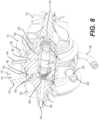
- the bearing housing 126 defines a bearing chamber 128 for receiving a bearing cartridge 130 that rotatably supports the shaft 106 relative to the bearing housing 126.
- the bearing chamber 128 is a cylindrical bore coaxial with the shaft 106.
- the bearing housing 126 also defines a lubricant inlet 140 for feeding lubricant (in this case oil) into the bearing housing 126 to lubricate the bearing cartridge 130 and a lubricant outlet 142 for discharging lubricant from the bearing housing 126.
- the lubricant inlet 140 is fitted with an inlet tube 144 for connecting the inlet 140 to a lubricant source and the lubricant outlet 142 is fitted with an outlet tube 146 for connecting the outlet 142 to another power plant component to which lubricant can be routed, as will be discussed in more detail further below.
- the turbine housing 108 is attached to an annular flange 131 ( Figs. 5 , 7 ) of the bearing housing 126 by a clamp 121.
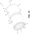
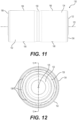
- the bearing cartridge 130 includes an inner ring 132 mounted to the shaft 106 and an outer ring 134 disposed between the inner ring 132 and the bearing housing 126.
- the inner and outer rings 132, 134 extend along an axis 125 that is coincident with the axis 115 of the shaft 106.
- the bearing cartridge 130 includes a first plurality of rolling elements 136 radially disposed between the inner and outer rings 132, 134 and a second plurality of rolling elements 138 radially disposed between the inner and outer rings 132, 134.
- the rolling elements 136 are held in place relative to one another by a cage 137.
- the rolling elements 138 are held in place relative to one another by a cage 139.
- the first and second plurality of rolling elements 136, 138 are axially spaced apart from one another.
- an inner bearing space 148 ( Fig. 13 ) is defined between the inner and outer rings 132, 134.
- the inner ring 132 includes two inner ring parts 133, 135 that are axially adjacent to one another.
- the two inner ring parts 133, 135 are identical and thus have the same shape and dimensions. The inclusion of two inner ring parts 133, 135 can facilitate the assembly of the bearing cartridge 130 onto the shaft 106.
- the outer ring 134 is sized such that a radial gap 150 is defined, radially, between the outer ring 134 and the bearing housing 126. More specifically, as shown in Fig. 13 , an outer surface 152 of the outer ring 134 has an outer radius R that is smaller than a radius RBC ( Fig. 9 ) of the bearing chamber 128 of the bearing housing 126. The difference between the radius R of the outer ring 134 and the radius RBC of the bearing chamber 128 results in the radial gap 150 defined between the outer ring 134 and the bearing chamber 128.
- the lubricant inlet 140 opens into the radial gap 150 in order to feed lubricant therein.
- the lubricant inlet 140 is located axially between opposite ends 154, 156 of the outer ring 134 and, more specifically, is generally aligned with an axial center of the outer ring 134 (i.e., a midpoint between the ends 154, 156 of the outer ring 134).
- lubricant (denoted as 155 in Fig. 16 ) flows into the radial gap 150 from the lubricant inlet 140 and radially separates the outer ring 134 from the bearing housing 126.
- the lubricant 155 flowing through and filling the radial gap 150 acts as a thin dampening film which can be helpful to absorb vibrations that occur due to the rotation of the shaft 106, the turbine wheel 110 and the compressor wheel 120.
- the radial gap 150 extends along a majority of a length L ( Fig. 13 ) of the outer ring 134. More specifically, the radial gap 150 extends along the entirety of the length L of the outer ring 134.
- the outer surface 152 of the outer ring 134 defines a radial recess 158 that is aligned with the axial center of the outer ring 134.
- the radial recess 158 is generally aligned with the lubricant inlet 140. This may facilitate flowing of lubricant into the radial gap 150.
- the outer ring 134 As the outer ring 134 is radially separated from the bearing housing 126 by lubricant circulating in the radial gap 150, the outer ring 134 is movable, and more specifically rotatable, relative to the bearing housing 126. Moreover, as will be described below, the outer ring 134 is axially movable relative to the bearing housing 126 due to axial gaps that are axially adjacent to the outer ring 134.
- the length L of the outer ring 134 is smaller than a length LBC ( Fig. 8 ) of the bearing chamber 128.
- the difference between the lengths L, LBC of the outer ring 134 and the bearing chamber 128 results in an axial gap 160 defined between the end 154 of the outer ring 134 and the bearing housing 126 and, as will be described in more detail below, an axial gap 190 defined at the end 156 of the outer ring 134.
- lubricant flows into the axial gap 160 and axially separates the outer ring 134 from the bearing housing 126.
- the lubricant flowing through and filling the axial gap 160 acts as a thin dampening film which can be helpful to absorb vibrations.
- the radial gap 150 has a radial dimension RD that is substantially equal to an axial dimension AD of the axial gap 160.
- the radial dimension RD of the radial gap 150 is equal to a difference between a radius RBC of the bearing chamber 128 and the radius R of the outer surface 152 of the outer ring 134.
- the axial dimension AD of the axial gap 160 is equal to half of a difference between the length LBC of the bearing chamber 128 and the length L of the outer ring 134 when the outer ring 134 is centered relative to the bearing chamber 128. It is understood that the axial dimension AD can increase or decrease as the outer ring 134 moves axially relative to the bearing chamber 128.
- Fig. 16 illustrates the radial and axial gaps 150, 160, 190 with their relative dimensions exaggerated for visual reference.
- the outer ring 134 defines bores 162 that extend from the outer surface 152 to an inner surface 164 (opposite the outer surface 152) of the outer ring 134.
- lubricant flowing into the radial gap 150 from the lubricant inlet 140 flows into the inner bearing space 148 through the bores 162 and lubricates the first and second plurality of rolling elements 136, 138.
- the outer ring 134 defines four bores 162. It is contemplated that the outer ring 134 could comprise less or more bores 162 in alternative implementations (e.g., at least one bore 162, five bores 162, etc.).
- each bore 162 is located axially between the first and second plurality of rolling elements 136, 138. More specifically, each bore 162 is located axially between the lubricant inlet 140 and one of the first and second plurality of rolling elements 136, 138. For instance, in this example, a given one of the bores 162 is located axially between the lubricant inlet 140 (i.e., the axial center of the outer ring 134) and the first plurality of rolling elements 136 while another one of the bores 162 is located axially between the lubricant inlet 140 (i.e., the axial center of the outer ring 134) and the second plurality of rolling elements 138.
- a given one of the bores 162 is located axially between the axial center of the outer ring 134 and the end 154 of the outer ring while another one of the bores 162 is located axially between the axial center of the outer ring 134 and the end 156 of the outer ring 134.
- radial recesses 166 are defined in the outer surface 152 of the outer ring 134.
- the radial recesses 166 are axially aligned with the bores 162 such that, in this implementation, the outer surface 152 defines one radial recess 166 between the lubricant inlet 140 and the first plurality of rolling elements 136, and another radial recess 166 between the lubricant inlet 140 and the second plurality of rolling elements 138.
- the outer surface 152 defines one radial recess 166 between the axial center of the outer ring 134 and the end 154 of the outer ring 134 and another radial recess 166 between the axial center of the housing 134 and the end 154 of the outer ring 134.
- radial recess 166 is defined in the outer surface 152 for each bore 162. The bores 162 extend from a given one of the radial recesses 166 to the inner surface 164 of the outer ring 134.
- the turbocharger 100 also comprises a compressor backplate 170 for supporting the compressor housing 118.
- the compressor backplate 170 which is mounted to the bearing housing 126, is disposed axially between the bearing housing 126 and the compressor wheel 120.
- the compressor backplate 170 has an inner side 172 facing the bearing housing 126 and an outer side 174 facing the compressor wheel 120.
- the inner side 172 of the compressor backplate 170 closes the bearing chamber 128 such as to enclose the bearing cartridge 130 within the bearing chamber 128.
- the compressor backplate 170 is affixed to the bearing housing 126. More specifically, an annular flange 178 on the inner side 172 of the compressor backplate 170 is screwed onto the bearing housing 126. To that end, a radially inner side of the flange 178 has threads 180 for screwing the compressor backplate 170 onto the bearing housing 126.
- the bearing housing 126 has a corresponding outer annular surface 182 that is threaded to engage the threads 180 of the flange 178. Screwing the compressor backplate 170 to the bearing housing 126 in this manner may facilitate adaptability of the turbocharger 100 to different types of turbine housings. For instance, if a different size of turbine housing 108 is desired, a different size of compressor backplate 170 is installed albeit with the same flange 178 and threads 180.
- a sealing carrier 184 is mounted to the shaft 106 (e.g., via a press-fit) and positioned within a central bore 186 of the compressor backplate 170.
- the sealing carrier 184 is generally cylindrical and defines a pair of radial grooves for receiving therein respective sealing rings 188 that provide a seal between the sealing carrier 184 and the compressor backplate 170 to prevent or otherwise minimize lubricant leaks from the bearing chamber 128.
- the sealing rings 188 are split rings, each sealing ring 188 having two ends 189, 191 defining a gap 193 therebetween.
- each sealing ring 188 has an outer peripheral surface 195 which faces the compressor backplate 170.
- the sealing rings 188 are tensioned such that the outer peripheral surfaces 195 of the sealing rings 188 are in contact with the central bore 186 of the compressor backplate 170.
- the sealing rings 188 are positioned such that their respective gaps 193 are circumferentially offset from one another (i.e., unaligned with respect to one another).
- the sealing rings 188 have a structure identical or similar to a piston ring and can be installed with a piston ring installation tool.
- the axial gap 160 is defined between the end 154 of the outer ring 134 and the bearing housing 126, as shown in Fig. 16
- the axial gap 190 is defined between the end 156 of the outer ring 134 and an inner surface 176 on the inner side 172 of the compressor backplate 170.
- lubricant flows into the axial gap 190 and axially separates the outer ring 134 from the compressor backplate 170.
- the outer ring 134 is axially spaced apart from the bearing housing 126 at the end 154 and from the compressor backplate 170 at the opposite end 156.
- the lubricant flowing through and filling the axial gap 190 acts as a thin dampening film which can be helpful to absorb vibrations.
- the axial gap 190 has the same axial dimension AD as the axial gap 160 when the outer ring 134 is centered relative to the bearing chamber 128 such that the axial dimension AD of the axial gap 190 is substantially equal to the radial dimension RD of the radial gap 150.
- the axial dimension AD of the axial gap 190 is equal to half of a difference between the length LBC of the bearing chamber 128 and the length L of the outer ring 134.
- the axial dimension AD of the axial gap 190 can increase or decrease as the outer ring 134 moves axially relative to the bearing chamber 128.
- the compressor backplate 170 defines passages for lubricant to flow from the bearing chamber 128 to the lubricant outlet 142.
- the inner surface 176 of the compressor backplate 170 defines a plurality of radially-extending passages 192 that extend outwardly from the central bore 186.
- the radially-extending passages 192 are equally spaced apart from one another and are in line, radially, with the outer ring 134.
- the inner surface 176 of the compressor backplate 170 also defines an annular passage 194 that is connected to the radially-extending passages 192. As shown in Fig.
- the radially-extending passages 192 are enclosed, opposite the inner surface 176, by a surface of the bearing housing 126.
- lubricant flows from the radial gap 150 and the axial gap 190 into the radially-extending passages 192 and, flowing along a length of the radially-extending passages 192, then flows into the annular passage 194.
- the bearing housing 126 has a chamfered edge 175 ( Fig. 9 ) to provide a gap between the end 156 of the outer ring 134 and the bearing housing such as to promote lubricant flow to the radially-extending passages 192.
- lubricant is made to flow back into the bearing housing 126. More particularly, the annular passage 194 opens into a lubricant collecting space 196 defined by the bearing housing 126 and which is configured for collecting lubricant flowing out of the bearing cartridge 130.
- the lubricant collecting space 196 is axially coextensive with the bearing chamber 128 and is radially separated from the bearing chamber 128 by a wall 198 of the bearing housing 126.
- the lubricant collecting space 196 is connected to the lubricant outlet 142 and includes an enlarged portion 202 and a reduced portion 204.
- the enlarged portion 202 opens into the lubricant outlet 142 and extends radially further than the reduced portion 204.
- lubricant flows into the lubricant collecting space 196 and then into the lubricant outlet 142 and out of the bearing housing 126.
- the bearing chamber 128 opens, through an annular passage 206 defined between the shaft 106 and the bearing housing 126, into an annular cavity 208 defined by the bearing housing 126.
- the annular cavity 208 is in communication with the reduced portion 204 of the lubricant collecting space 196.
- lubricant is discharged from an axial end of the bearing chamber 128 through, on one end, the passages 192, 194 of the compressor backplate 170 and, at the opposite end, through the annular passage 206 and the annular cavity 208.
- the bearing chamber 128 is not connected to any radially-extending outlets for lubricant along the length of the bearing cartridge 130.
- the shaft 106 has a projection 210 ( Fig. 9 ) axially positioned within the annular cavity 208 to at least partially project lubricant that flows into the annular cavity 208 against the inner wall of the annular cavity 208.
- the projection 210 has a generally conical surface 211 that defines an obtuse angle relative to the axis 115 of the shaft 106.
- lubricant flowing into the annular cavity 208 from the bearing chamber 128 contacts the conical surface 211 and, due to the elevated rotating speed of the shaft 106, is projected against the inner wall of the annular cavity 208. This may be helpful to direct the flow of lubricant towards the lubricant collecting space 196.
- lubrication system described above allows lubrication of the bearing cartridge 130 with a significantly small flow of lubricant.
- lubricant flows through the bearing housing 126 at a rate of less than or equal to 2000 cm 3 per hour, in some cases at a rate of less than or equal to 200 cm 3 per hour, and in some cases even less.
- the lubricant flows through the bearing housing 126 at a rate of 170 cm 3 per hour. This is substantially less than in conventional turbochargers and, in particular, compared to turbochargers that implement a ball bearing cartridge which typically require a high amount of lubricant flow.
- the lubricant flowing into the bearing housing 126 has a relatively low pressure.
- the lubricant flowing through the housing 126 has a pressure of less than or equal to 1 bar.
- the pressure of the lubricant flowing through the bearing housing 126 is between 0.3 bar and 0.8 bar. In some cases, the pressure of the lubricant flowing through the housing 126 is less than or equal to 0.1 bar.
- the turbocharger 100 comprises a cooling system 215 for cooling the turbocharger 100 and, in particular, the bearing housing 126.
- the cooling system 215 includes a coolant chamber 216 defined in the housing 126 and through which coolant circulates.
- the cooling system 215 also includes a plurality of ports 218, 220, 222, 224 in fluid communication with the coolant chamber 216.
- the port 218 is an inlet port for feeding coolant into the coolant chamber 216
- the port 220 is an outlet port for discharging coolant from the coolant chamber 216
- the remaining ports 222, 224 are blocked via plugs 226 positioned in the ports 222, 224.
- any one of the ports 218, 220, 222, 224 can be made the inlet port or the outlet port in alternative implementations.
- any two of the four ports 218, 220, 222, 224 can be selectively blocked by the plugs 226 while any other two of the four ports 218, 220, 222, 224 can be used as the inlet and outlet ports of the cooling system 215.
- This provides more options as to the location of the coolant inlet and outlet of the bearing housing 126 which may facilitate positioning of the turbocharger 100 within the power plant 5.
- the cooling system 215 could comprise less or more ports (e.g., three ports, five ports, etc.) in alternative implementations.
- lubricant that flows through the bearing housing 126 is pumped thereto from other components of the engine 10 and, after flowing through the bearing housing 126, is routed through other components of the engine 10 thereafter.
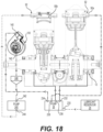
- the oil pump 26 is fluidly connected to the lubricant reservoir 28, the crankcase 12, and the turbocharger 100 such as to pump lubricant from the lubricant reservoir 28 to the crankcase 12, to one of the exhaust valves 90a, 90b, and to the turbocharger 100. More specifically, the oil pump 26 has an inlet port 230 for receiving lubricant from the lubricant reservoir 28, an outlet port 232 for feeding lubricant from the oil pump 26 to the crankcase 12 (and more specifically to a bearing supporting the crankshaft 18), an outlet port 238 for feeding lubricant to the exhaust valve 90a and an outlet port 234 for feeding lubricant from the oil pump 26 to the turbocharger 100.
- the lubricant enters the turbocharger 100 through the lubricant inlet 140 of the bearing housing 126.
- the oil pump 26 also has an additional outlet port 236 for feeding lubricant to the bearings supporting the crankshaft 18 in the crankcase 12 (e.g., such that the oil pump 26 is connected to two inlets of the crankcase 12).
- the power plant 5 also includes another lubricant (oil) pump 240 that is fluidly connected to the turbocharger 100 and the exhaust valve 90b for pumping lubricant from the turbocharger 100 to the exhaust valve 90b.
- a reservoir 246 is connected to the turbocharger 100 which receives lubricant flowing out of the turbocharger 100 through the lubricant outlet 142 and the outlet tube 146.
- the volume of the reservoir 246 is approximately 100 cc, but it is contemplated that the volume could be more or less than 100 cc.
- the reservoir 246 is fluidly connected to the airbox 252 to vent the reservoir 246 such as to discharge any air contained in the lubricant to the airbox 252.
- the oil pump 240 has an inlet port 242 for receiving lubricant from the reservoir 246 and an outlet port 244 for feeding lubricant from the oil pump 240 to the exhaust valve 90b. It is contemplated that the oil pump 240 could pump lubricant to both exhaust valves 90a, 90b. It is further contemplated that the oil pump 26 could pump lubricant to both exhaust valves 90a, 90b, or the oil pump 26 could not pump lubricant to the exhaust valves 90a, 90b.
- the oil pump 240 and the reservoir 246 are replaced by an oil pump that comprises a reed valve 250.
- the reed valve 250 comprises a reservoir 251 including an upper chamber 254 and a lower chamber 256 separated by a membrane 255 (i.e., a reed petal).
- the lower chamber 256 of the reed valve 250 is fluidly connected to the crankcase 12 via pressure feed line 258.
- the upper chamber 254 of the reed valve 250 is fluidly connected to the turbocharger 100 via the lubricant outlet 142 and the outlet tube 146, and to an airbox 252 of the engine 10 configured to collect air.
- the reed valve 250 is fluidly connected to the airbox 252 to vent the reservoir 251 such as to discharge any air contained in the lubricant to the airbox 252 and/or to release extra pressure thereto.
- pressure pulsations generated within the crankcase 12 cause the reed valve 250 to open and close such as to pump lubricant to the exhaust valve assembly 92.
- a vacuum is created in the portion of the crankcase 12 beneath the piston 34.
- a resulting pressure differential causes movement of the reed petal 255 thus opening the reed valve 250 to allow lubricant received from the turbocharger 100 to pass from the upper chamber 254 to the lower chamber 256 which is fluidly connected to the exhaust valve assembly 92 to feed the lubricant thereto.
Landscapes
- Engineering & Computer Science (AREA)
- General Engineering & Computer Science (AREA)
- Mechanical Engineering (AREA)
- Chemical & Material Sciences (AREA)
- Combustion & Propulsion (AREA)
- Chemical Kinetics & Catalysis (AREA)
- General Chemical & Material Sciences (AREA)
- Supercharger (AREA)
Claims (6)
- Fahrzeugantriebsaggregat (5), umfassend:einen Verbrennungsmotor (10), umfassend:ein Kurbelgehäuse (12);eine Kurbelwelle (18), die mindestens teilweise im Kurbelgehäuse (12) angeordnet ist;einen Zylinderblock (14), der mit dem Kurbelgehäuse verbunden ist, wobei der Zylinderblock einen Zylinder (30) definiert, der eine Zylinderachse (32) definiert, wobei der Zylinder mindestens eine Auslassöffnung (52) zum Abführen von Abgasfluid aus dem Zylinder und mindestens eine Einlassöffnung (42) zum Aufnehmen von Luft in den Zylinder definiert,einen Kolben (34), der beweglich innerhalb des Zylinders angeordnet und mit der Kurbelwelle funktionsmäßig verbunden ist, wobei der Kolben entlang der Zylinderachse in einer Hin- und Herbewegung beweglich ist;eine Auslassventilanordnung (92) zum selektiven Öffnen und mindestens partiellen Schließen der mindestens einen Auslassöffnung; undeinen Schmiermittelvorratsbehälter (28) zur Aufnahme von Schmiermittel;einen Turbolader (100), der mit der mindestens einen Einlassöffnung und der mindestens einen Auslassöffnung in Fluidverbindung steht; undeine erste Pumpe (26), die mit dem Schmiermittelvorratsbehälter, dem Kurbelgehäuse und dem Turbolader in Fluidverbindung steht, um Schmiermittel aus dem Schmiermittelvorratsbehälter zum Kurbelgehäuse und zum Turbolader zu pumpen; gekennzeichnet durcheine zweite Pumpe (240), die mit dem Turbolader und der Auslassventilanordnung in Fluidverbindung steht, um Schmiermittel vom Turbolader zur Auslassventilanordnung zu pumpen.
- Antriebsaggregat nach Anspruch 1, wobei die erste Pumpe einschließt:mindestens eine Einlassöffnung (230) zum Aufnehmen von Schmiermittel aus dem Schmiermittelvorratsbehälter (28);mindestens eine erste Auslassöffnung (232) zum Zuführen von Schmiermittel von der ersten Pumpe zum Kurbelgehäuse; undmindestens eine zweite Auslassöffnung (234) zum Zuführen von Schmiermittel von der ersten Pumpe zum Turbolader.
- Antriebsaggregat nach Anspruch 1 oder 2, wobei:die zweite Pumpe ein Membranventil (250) umfasst, das mit dem Kurbelgehäuse in Fluidverbindung steht; undwährend des Betriebs des Motors innerhalb des Kurbelgehäuses erzeugte Druckpulsationen bewirken, dass sich das Membranventil öffnet und schließt, um Schmiermittel zur Auslassventilanordnung zu pumpen.
- Antriebsaggregat nach Anspruch 3, wobei:das Membranventil einen Vorratsbehälter (251) umfasst;der Vorratsbehälter eine obere und eine untere Kammer (254, 256) und eine Membran (255) umfasst, die die obere und die untere Kammer trennt;die untere Kammer (256) fluidisch mit dem Kurbelgehäuse und der Auslassventilanordnung verbunden ist;die obere Kammer (254) fluidisch mit dem Turbolader verbunden ist; unddie innerhalb des Kurbelgehäuses erzeugten Druckpulsationen eine Bewegung der Membran bewirken, sodass aus dem Turbolader aufgenommenes Schmiermittel von der zweiten Kammer zur ersten Kammer gelangen kann.
- Antriebsaggregat nach Anspruch 4, ferner umfassend einen Luftkasten (252), der mit der oberen Kammer (254) verbunden ist und so konfiguriert ist, dass er Luft sammelt, wobei das Membranventil fluidisch verbunden ist, um den Vorratsbehälter des Membranventils zu entlüften, um im Schmiermittel enthaltene Luft zum Luftkasten abzuführen.
- Antriebsaggregat nach Anspruch 1 oder 2, ferner umfassend:einen Vorratsbehälter (246) der fluidisch mit dem Turbolader verbunden ist, um aus dem Turbolader strömendes Schmiermittel aufzunehmen, wobei die zweite Pumpe Schmiermittel aus dem Vorratsbehälter aufnimmt; undeinen Luftkasten (252), der zum Sammeln von Luft konfiguriert ist, wobei der Vorratsbehälter fluidisch mit dem Luftkasten verbunden ist, um den Vorratsbehälter zu entlüften und im Schmiermittel enthaltene Luft zum Luftkasten abzuführen.
Applications Claiming Priority (3)
| Application Number | Priority Date | Filing Date | Title |
|---|---|---|---|
| US201762590416P | 2017-11-24 | 2017-11-24 | |
| EP18808334.9A EP3714176B1 (de) | 2017-11-24 | 2018-11-23 | Turbolader für einen verbrennungsmotor |
| PCT/EP2018/082456 WO2019101974A1 (en) | 2017-11-24 | 2018-11-23 | Turbocharger for an internal combustion engine |
Related Parent Applications (2)
| Application Number | Title | Priority Date | Filing Date |
|---|---|---|---|
| EP18808334.9A Division-Into EP3714176B1 (de) | 2017-11-24 | 2018-11-23 | Turbolader für einen verbrennungsmotor |
| EP18808334.9A Division EP3714176B1 (de) | 2017-11-24 | 2018-11-23 | Turbolader für einen verbrennungsmotor |
Publications (3)
| Publication Number | Publication Date |
|---|---|
| EP4108943A1 EP4108943A1 (de) | 2022-12-28 |
| EP4108943B1 true EP4108943B1 (de) | 2023-12-27 |
| EP4108943C0 EP4108943C0 (de) | 2023-12-27 |
Family
ID=64477174
Family Applications (2)
| Application Number | Title | Priority Date | Filing Date |
|---|---|---|---|
| EP22190873.4A Active EP4108943B1 (de) | 2017-11-24 | 2018-11-23 | Kraftfahrzeugkraftwerk bestehend aus einem verbrennungsmotor mit turbolader |
| EP18808334.9A Active EP3714176B1 (de) | 2017-11-24 | 2018-11-23 | Turbolader für einen verbrennungsmotor |
Family Applications After (1)
| Application Number | Title | Priority Date | Filing Date |
|---|---|---|---|
| EP18808334.9A Active EP3714176B1 (de) | 2017-11-24 | 2018-11-23 | Turbolader für einen verbrennungsmotor |
Country Status (3)
| Country | Link |
|---|---|
| US (1) | US11131242B2 (de) |
| EP (2) | EP4108943B1 (de) |
| WO (1) | WO2019101974A1 (de) |
Families Citing this family (1)
| Publication number | Priority date | Publication date | Assignee | Title |
|---|---|---|---|---|
| CN115427667B (zh) * | 2020-03-12 | 2025-06-24 | 莫托塔西那里股份有限公司 | 改进的簧片阀以及簧片阀空气箱 |
Family Cites Families (37)
| Publication number | Priority date | Publication date | Assignee | Title |
|---|---|---|---|---|
| US2853948A (en) * | 1955-08-19 | 1958-09-30 | Thompson Prod Inc | Lubricating and cooling arrangement for a bearing assembly |
| GB935457A (en) * | 1960-11-14 | 1963-08-28 | Eng Productions Clevedon Ltd | Improvements in sleeve bearings for turbochargers and the like |
| US4420160A (en) * | 1980-03-10 | 1983-12-13 | The Garrett Corporation | Face seal system |
| US4798523A (en) * | 1986-12-19 | 1989-01-17 | Allied-Signal Inc. | Turbocharger bearing and lubrication system |
| JPH0540273Y2 (de) * | 1988-04-26 | 1993-10-13 | ||
| JPH079247B2 (ja) * | 1988-06-07 | 1995-02-01 | 日産自動車株式会社 | 転がり軸受の制振装置 |
| DE3825326A1 (de) * | 1988-07-26 | 1990-02-01 | Kugelfischer G Schaefer & Co | Waelzlager fuer abgasturbolader |
| US5145334A (en) * | 1989-12-12 | 1992-09-08 | Allied-Signal Inc. | Turbocharger bearing retention and lubrication system |
| US5106208A (en) * | 1991-04-17 | 1992-04-21 | General Electric Company | Proportioned piston ring seals |
| US5207511A (en) * | 1991-07-22 | 1993-05-04 | General Electric Company | Squeeze film damper oil control |
| US5921683A (en) * | 1997-09-12 | 1999-07-13 | United Technologies Corporation | Bearing arrangement for air cycle machine |
| US6877901B2 (en) | 2001-10-16 | 2005-04-12 | William E. Wollenweber | Bearing system for high-speed rotating machinery |
| US7025579B2 (en) * | 2001-10-16 | 2006-04-11 | Innovative Turbo Systems Corporation | Bearing system for high-speed rotating machinery |
| US7104693B2 (en) | 2004-06-28 | 2006-09-12 | Honeywell International, Inc. | Multi-thickness film layer bearing cartridge and housing |
| US7214037B2 (en) * | 2004-06-28 | 2007-05-08 | Honeywell International, Inc. | Retention of ball bearing cartridge for turbomachinery |
| US7832938B2 (en) * | 2006-07-19 | 2010-11-16 | Mckeirnan Jr Robert D | Floating bearing cartridge for a turbocharger shaft |
| US7670056B2 (en) * | 2007-03-22 | 2010-03-02 | Honeywell International Inc. | Stepped outer diameter semi-floating bearing |
| DE102007027869B4 (de) | 2007-06-18 | 2010-04-29 | Continental Automotive Gmbh | Turbolader mit einem Turboladergehäuse |
| JP2010133266A (ja) * | 2008-12-02 | 2010-06-17 | Toyota Motor Corp | 過給機の軸受装置 |
| CN102414428B (zh) * | 2009-03-26 | 2013-01-23 | 株式会社小松制作所 | 发动机 |
| KR20120014901A (ko) | 2009-04-20 | 2012-02-20 | 보르그워너 인코퍼레이티드 | 롤링 요소 베어링 카트리지를 위한 절연 및 감쇠 슬리브 |
| US8961128B2 (en) | 2009-08-26 | 2015-02-24 | Honeywell International Inc. | Bearing spacer and housing |
| JP2011153569A (ja) | 2010-01-27 | 2011-08-11 | Toyota Motor Corp | 過給機のタービン軸支持用軸受の位置決め構造 |
| US20110236193A1 (en) * | 2010-03-25 | 2011-09-29 | Schaeffler Technologies Gmbh & Co. Kg | Turbocharger bearing lubrication |
| US9046036B2 (en) * | 2011-05-31 | 2015-06-02 | Honeywell International Inc. | Bearing assembly |
| EP2698504A1 (de) | 2011-06-17 | 2014-02-19 | Aktiebolaget SKF | Turbolader, insbesondere für einen Verbrennungsmotor |
| DE102011081200A1 (de) * | 2011-08-18 | 2013-02-21 | Bosch Mahle Turbo Systems Gmbh & Co. Kg | Wälzlageranordnung eines Abgasturboladers |
| DE102011081419A1 (de) | 2011-08-23 | 2013-02-28 | Schaeffler Technologies AG & Co. KG | Quetschöldämpfer |
| EP2743461A1 (de) * | 2011-08-30 | 2014-06-18 | Aktiebolaget SKF | Turbolader mit thermischer Schutzhülse zwischen innerem Lagerring und Welle |
| EP2565418B1 (de) * | 2011-08-30 | 2014-03-05 | Aktiebolaget SKF | Turbolader mit Lagerhuelse zwischen inneren Lagerring und Welle |
| GB2497943A (en) * | 2011-12-22 | 2013-07-03 | Cummins Ltd | Internal combustion engine and waste heat recovery system |
| EP2657553B1 (de) * | 2012-04-23 | 2014-12-31 | Aktiebolaget SKF | Lager, Lagerbaugruppe mit solch einem Lager und Turbolader mit solch einer Lagerbaugruppe |
| JP6250923B2 (ja) | 2012-09-20 | 2017-12-20 | 株式会社ジェイテクト | 軸受装置 |
| US9404399B2 (en) | 2013-07-31 | 2016-08-02 | Brp-Rotax Gmbh & Co Kg | Exhaust valve assembly for a two-stroke engine |
| US9915172B2 (en) | 2015-03-09 | 2018-03-13 | Caterpillar Inc. | Turbocharger with bearing piloted compressor wheel |
| US9745992B2 (en) * | 2015-08-30 | 2017-08-29 | Honeywell International Inc. | Turbocharger bearing damper assembly |
| US10316742B2 (en) * | 2016-05-13 | 2019-06-11 | Garrett Transportation I Inc. | Turbocharger assembly |
-
2018
- 2018-11-23 US US16/766,626 patent/US11131242B2/en active Active
- 2018-11-23 WO PCT/EP2018/082456 patent/WO2019101974A1/en not_active Ceased
- 2018-11-23 EP EP22190873.4A patent/EP4108943B1/de active Active
- 2018-11-23 EP EP18808334.9A patent/EP3714176B1/de active Active
Also Published As
| Publication number | Publication date |
|---|---|
| EP3714176B1 (de) | 2022-09-28 |
| WO2019101974A1 (en) | 2019-05-31 |
| US11131242B2 (en) | 2021-09-28 |
| EP4108943A1 (de) | 2022-12-28 |
| EP3714176A1 (de) | 2020-09-30 |
| US20210010420A1 (en) | 2021-01-14 |
| EP4108943C0 (de) | 2023-12-27 |
Similar Documents
| Publication | Publication Date | Title |
|---|---|---|
| JP4662668B2 (ja) | 燃料のためのポンプ装置 | |
| US5876188A (en) | Oil pump arrangement for four-cycle outboard motor | |
| CN102562217B (zh) | 润滑回路布置 | |
| US11891930B2 (en) | Exhaust valve assembly for a two-stroke internal combustion engine | |
| JP2004132378A (ja) | 共同噴射装置に特に適した高圧ポンプ | |
| US7219645B2 (en) | Oil pump for a motorcycle | |
| US20170074221A1 (en) | Fuel pump mounting structure for engine | |
| US6904884B2 (en) | Balance device for engines | |
| US11131242B2 (en) | Turbocharger for an internal combustion engine | |
| US6974315B2 (en) | Reduced friction gerotor | |
| US20120240892A1 (en) | Efficient oil treatment for radial engine | |
| CN109268181B (zh) | 一种四缸径向布置的电控高压共轨供油泵 | |
| AU2021329294B2 (en) | Head assembly with rotary valves for an internal combustion engine | |
| US8925502B1 (en) | Hydraulically actuated valve assembly for an engine | |
| US11015494B2 (en) | Engine oil pump cover with seal | |
| CN102844524B (zh) | 发动机 | |
| WO2020043881A1 (en) | Piston assembly for an internal combustion engine | |
| JP2025093431A (ja) | エンジン | |
| JPH085342Y2 (ja) | 低粘性燃料油用ラジアルピストンポンプ | |
| EP1774175B1 (de) | Flüssigkeitspumpe mit radialen zylindern | |
| AU2012202306A1 (en) | Efficient lubricant treatment for radial engine | |
| CA2774521A1 (en) | Efficient lubricant treatment for radial engine | |
| JP2001303918A (ja) | 2サイクルエンジンの潤滑系 |
Legal Events
| Date | Code | Title | Description |
|---|---|---|---|
| PUAI | Public reference made under article 153(3) epc to a published international application that has entered the european phase |
Free format text: ORIGINAL CODE: 0009012 |
|
| STAA | Information on the status of an ep patent application or granted ep patent |
Free format text: STATUS: THE APPLICATION HAS BEEN PUBLISHED |
|
| AC | Divisional application: reference to earlier application |
Ref document number: 3714176 Country of ref document: EP Kind code of ref document: P |
|
| AK | Designated contracting states |
Kind code of ref document: A1 Designated state(s): AL AT BE BG CH CY CZ DE DK EE ES FI FR GB GR HR HU IE IS IT LI LT LU LV MC MK MT NL NO PL PT RO RS SE SI SK SM TR |
|
| STAA | Information on the status of an ep patent application or granted ep patent |
Free format text: STATUS: REQUEST FOR EXAMINATION WAS MADE |
|
| 17P | Request for examination filed |
Effective date: 20230614 |
|
| GRAP | Despatch of communication of intention to grant a patent |
Free format text: ORIGINAL CODE: EPIDOSNIGR1 |
|
| RBV | Designated contracting states (corrected) |
Designated state(s): AL AT BE BG CH CY CZ DE DK EE ES FI FR GB GR HR HU IE IS IT LI LT LU LV MC MK MT NL NO PL PT RO RS SE SI SK SM TR |
|
| STAA | Information on the status of an ep patent application or granted ep patent |
Free format text: STATUS: GRANT OF PATENT IS INTENDED |
|
| RIC1 | Information provided on ipc code assigned before grant |
Ipc: F02B 37/24 20060101ALN20230706BHEP Ipc: F16C 37/00 20060101ALN20230706BHEP Ipc: F16C 19/18 20060101ALN20230706BHEP Ipc: F16C 17/02 20060101ALI20230706BHEP Ipc: F01D 25/20 20060101ALI20230706BHEP Ipc: F02B 37/00 20060101ALI20230706BHEP Ipc: F16C 21/00 20060101ALI20230706BHEP Ipc: F16C 33/66 20060101ALI20230706BHEP Ipc: F16C 27/04 20060101ALI20230706BHEP Ipc: F16C 19/52 20060101ALI20230706BHEP Ipc: F16C 19/08 20060101AFI20230706BHEP |
|
| INTG | Intention to grant announced |
Effective date: 20230720 |
|
| GRAS | Grant fee paid |
Free format text: ORIGINAL CODE: EPIDOSNIGR3 |
|
| GRAA | (expected) grant |
Free format text: ORIGINAL CODE: 0009210 |
|
| STAA | Information on the status of an ep patent application or granted ep patent |
Free format text: STATUS: THE PATENT HAS BEEN GRANTED |
|
| AC | Divisional application: reference to earlier application |
Ref document number: 3714176 Country of ref document: EP Kind code of ref document: P |
|
| AK | Designated contracting states |
Kind code of ref document: B1 Designated state(s): AL AT BE BG CH CY CZ DE DK EE ES FI FR GB GR HR HU IE IS IT LI LT LU LV MC MK MT NL NO PL PT RO RS SE SI SK SM TR |
|
| REG | Reference to a national code |
Ref country code: GB Ref legal event code: FG4D |
|
| REG | Reference to a national code |
Ref country code: CH Ref legal event code: EP |
|
| REG | Reference to a national code |
Ref country code: DE Ref legal event code: R096 Ref document number: 602018063498 Country of ref document: DE |
|
| REG | Reference to a national code |
Ref country code: IE Ref legal event code: FG4D |
|
| U01 | Request for unitary effect filed |
Effective date: 20240124 |
|
| U07 | Unitary effect registered |
Designated state(s): AT BE BG DE DK EE FI FR IT LT LU LV MT NL PT SE SI Effective date: 20240130 |
|
| PG25 | Lapsed in a contracting state [announced via postgrant information from national office to epo] |
Ref country code: GR Free format text: LAPSE BECAUSE OF FAILURE TO SUBMIT A TRANSLATION OF THE DESCRIPTION OR TO PAY THE FEE WITHIN THE PRESCRIBED TIME-LIMIT Effective date: 20240328 |
|
| PG25 | Lapsed in a contracting state [announced via postgrant information from national office to epo] |
Ref country code: ES Free format text: LAPSE BECAUSE OF FAILURE TO SUBMIT A TRANSLATION OF THE DESCRIPTION OR TO PAY THE FEE WITHIN THE PRESCRIBED TIME-LIMIT Effective date: 20231227 |
|
| PG25 | Lapsed in a contracting state [announced via postgrant information from national office to epo] |
Ref country code: GR Free format text: LAPSE BECAUSE OF FAILURE TO SUBMIT A TRANSLATION OF THE DESCRIPTION OR TO PAY THE FEE WITHIN THE PRESCRIBED TIME-LIMIT Effective date: 20240328 Ref country code: ES Free format text: LAPSE BECAUSE OF FAILURE TO SUBMIT A TRANSLATION OF THE DESCRIPTION OR TO PAY THE FEE WITHIN THE PRESCRIBED TIME-LIMIT Effective date: 20231227 |
|
| PG25 | Lapsed in a contracting state [announced via postgrant information from national office to epo] |
Ref country code: RS Free format text: LAPSE BECAUSE OF FAILURE TO SUBMIT A TRANSLATION OF THE DESCRIPTION OR TO PAY THE FEE WITHIN THE PRESCRIBED TIME-LIMIT Effective date: 20231227 Ref country code: NO Free format text: LAPSE BECAUSE OF FAILURE TO SUBMIT A TRANSLATION OF THE DESCRIPTION OR TO PAY THE FEE WITHIN THE PRESCRIBED TIME-LIMIT Effective date: 20240327 Ref country code: HR Free format text: LAPSE BECAUSE OF FAILURE TO SUBMIT A TRANSLATION OF THE DESCRIPTION OR TO PAY THE FEE WITHIN THE PRESCRIBED TIME-LIMIT Effective date: 20231227 |
|
| PG25 | Lapsed in a contracting state [announced via postgrant information from national office to epo] |
Ref country code: IS Free format text: LAPSE BECAUSE OF FAILURE TO SUBMIT A TRANSLATION OF THE DESCRIPTION OR TO PAY THE FEE WITHIN THE PRESCRIBED TIME-LIMIT Effective date: 20240427 |
|
| PG25 | Lapsed in a contracting state [announced via postgrant information from national office to epo] |
Ref country code: CZ Free format text: LAPSE BECAUSE OF FAILURE TO SUBMIT A TRANSLATION OF THE DESCRIPTION OR TO PAY THE FEE WITHIN THE PRESCRIBED TIME-LIMIT Effective date: 20231227 |
|
| PG25 | Lapsed in a contracting state [announced via postgrant information from national office to epo] |
Ref country code: SK Free format text: LAPSE BECAUSE OF FAILURE TO SUBMIT A TRANSLATION OF THE DESCRIPTION OR TO PAY THE FEE WITHIN THE PRESCRIBED TIME-LIMIT Effective date: 20231227 |
|
| PG25 | Lapsed in a contracting state [announced via postgrant information from national office to epo] |
Ref country code: SM Free format text: LAPSE BECAUSE OF FAILURE TO SUBMIT A TRANSLATION OF THE DESCRIPTION OR TO PAY THE FEE WITHIN THE PRESCRIBED TIME-LIMIT Effective date: 20231227 Ref country code: SK Free format text: LAPSE BECAUSE OF FAILURE TO SUBMIT A TRANSLATION OF THE DESCRIPTION OR TO PAY THE FEE WITHIN THE PRESCRIBED TIME-LIMIT Effective date: 20231227 Ref country code: RO Free format text: LAPSE BECAUSE OF FAILURE TO SUBMIT A TRANSLATION OF THE DESCRIPTION OR TO PAY THE FEE WITHIN THE PRESCRIBED TIME-LIMIT Effective date: 20231227 Ref country code: IS Free format text: LAPSE BECAUSE OF FAILURE TO SUBMIT A TRANSLATION OF THE DESCRIPTION OR TO PAY THE FEE WITHIN THE PRESCRIBED TIME-LIMIT Effective date: 20240427 Ref country code: CZ Free format text: LAPSE BECAUSE OF FAILURE TO SUBMIT A TRANSLATION OF THE DESCRIPTION OR TO PAY THE FEE WITHIN THE PRESCRIBED TIME-LIMIT Effective date: 20231227 |
|
| PG25 | Lapsed in a contracting state [announced via postgrant information from national office to epo] |
Ref country code: PL Free format text: LAPSE BECAUSE OF FAILURE TO SUBMIT A TRANSLATION OF THE DESCRIPTION OR TO PAY THE FEE WITHIN THE PRESCRIBED TIME-LIMIT Effective date: 20231227 |
|
| PG25 | Lapsed in a contracting state [announced via postgrant information from national office to epo] |
Ref country code: PL Free format text: LAPSE BECAUSE OF FAILURE TO SUBMIT A TRANSLATION OF THE DESCRIPTION OR TO PAY THE FEE WITHIN THE PRESCRIBED TIME-LIMIT Effective date: 20231227 |
|
| REG | Reference to a national code |
Ref country code: DE Ref legal event code: R097 Ref document number: 602018063498 Country of ref document: DE |
|
| PLBE | No opposition filed within time limit |
Free format text: ORIGINAL CODE: 0009261 |
|
| STAA | Information on the status of an ep patent application or granted ep patent |
Free format text: STATUS: NO OPPOSITION FILED WITHIN TIME LIMIT |
|
| 26N | No opposition filed |
Effective date: 20240930 |
|
| U20 | Renewal fee for the european patent with unitary effect paid |
Year of fee payment: 7 Effective date: 20241127 |
|
| REG | Reference to a national code |
Ref country code: CH Ref legal event code: PL |
|
| PG25 | Lapsed in a contracting state [announced via postgrant information from national office to epo] |
Ref country code: MC Free format text: LAPSE BECAUSE OF FAILURE TO SUBMIT A TRANSLATION OF THE DESCRIPTION OR TO PAY THE FEE WITHIN THE PRESCRIBED TIME-LIMIT Effective date: 20231227 |
|
| REG | Reference to a national code |
Ref country code: CH Ref legal event code: PL |
|
| GBPC | Gb: european patent ceased through non-payment of renewal fee |
Effective date: 20241123 |
|
| PG25 | Lapsed in a contracting state [announced via postgrant information from national office to epo] |
Ref country code: CH Free format text: LAPSE BECAUSE OF NON-PAYMENT OF DUE FEES Effective date: 20241130 |
|
| PG25 | Lapsed in a contracting state [announced via postgrant information from national office to epo] |
Ref country code: GB Free format text: LAPSE BECAUSE OF NON-PAYMENT OF DUE FEES Effective date: 20241123 |
|
| PG25 | Lapsed in a contracting state [announced via postgrant information from national office to epo] |
Ref country code: IE Free format text: LAPSE BECAUSE OF NON-PAYMENT OF DUE FEES Effective date: 20241123 |
|
| U20 | Renewal fee for the european patent with unitary effect paid |
Year of fee payment: 8 Effective date: 20251126 |
|
| PG25 | Lapsed in a contracting state [announced via postgrant information from national office to epo] |
Ref country code: HU Free format text: LAPSE BECAUSE OF FAILURE TO SUBMIT A TRANSLATION OF THE DESCRIPTION OR TO PAY THE FEE WITHIN THE PRESCRIBED TIME-LIMIT; INVALID AB INITIO Effective date: 20181123 |
|
| PG25 | Lapsed in a contracting state [announced via postgrant information from national office to epo] |
Ref country code: CY Free format text: LAPSE BECAUSE OF FAILURE TO SUBMIT A TRANSLATION OF THE DESCRIPTION OR TO PAY THE FEE WITHIN THE PRESCRIBED TIME-LIMIT; INVALID AB INITIO Effective date: 20181123 |