EP4109022A1 - Elektrische heizvorrichtung und damit versehener wärmebehandlungsofen - Google Patents
Elektrische heizvorrichtung und damit versehener wärmebehandlungsofen Download PDFInfo
- Publication number
- EP4109022A1 EP4109022A1 EP20920315.7A EP20920315A EP4109022A1 EP 4109022 A1 EP4109022 A1 EP 4109022A1 EP 20920315 A EP20920315 A EP 20920315A EP 4109022 A1 EP4109022 A1 EP 4109022A1
- Authority
- EP
- European Patent Office
- Prior art keywords
- electric heater
- bar
- heater device
- side wall
- treatment furnace
- Prior art date
- Legal status (The legal status is an assumption and is not a legal conclusion. Google has not performed a legal analysis and makes no representation as to the accuracy of the status listed.)
- Pending
Links
Images





Classifications
-
- F—MECHANICAL ENGINEERING; LIGHTING; HEATING; WEAPONS; BLASTING
- F27—FURNACES; KILNS; OVENS; RETORTS
- F27D—DETAILS OR ACCESSORIES OF FURNACES, KILNS, OVENS OR RETORTS, IN SO FAR AS THEY ARE OF KINDS OCCURRING IN MORE THAN ONE KIND OF FURNACE
- F27D11/00—Arrangement of elements for electric heating in or on furnaces
- F27D11/02—Ohmic resistance heating
-
- F—MECHANICAL ENGINEERING; LIGHTING; HEATING; WEAPONS; BLASTING
- F27—FURNACES; KILNS; OVENS; RETORTS
- F27B—FURNACES, KILNS, OVENS OR RETORTS IN GENERAL; OPEN SINTERING OR LIKE APPARATUS
- F27B5/00—Muffle furnaces; Retort furnaces; Other furnaces in which the charge is held completely isolated
- F27B5/06—Details, accessories or equipment specially adapted for furnaces of these types
- F27B5/14—Arrangements of heating devices
-
- F—MECHANICAL ENGINEERING; LIGHTING; HEATING; WEAPONS; BLASTING
- F27—FURNACES; KILNS; OVENS; RETORTS
- F27D—DETAILS OR ACCESSORIES OF FURNACES, KILNS, OVENS OR RETORTS, IN SO FAR AS THEY ARE OF KINDS OCCURRING IN MORE THAN ONE KIND OF FURNACE
- F27D1/00—Casings; Linings; Walls; Roofs
- F27D1/0003—Linings or walls
- F27D1/0036—Linings or walls comprising means for supporting electric resistances in the furnace
-
- F—MECHANICAL ENGINEERING; LIGHTING; HEATING; WEAPONS; BLASTING
- F27—FURNACES; KILNS; OVENS; RETORTS
- F27B—FURNACES, KILNS, OVENS OR RETORTS IN GENERAL; OPEN SINTERING OR LIKE APPARATUS
- F27B5/00—Muffle furnaces; Retort furnaces; Other furnaces in which the charge is held completely isolated
- F27B5/06—Details, accessories or equipment specially adapted for furnaces of these types
- F27B5/14—Arrangements of heating devices
- F27B2005/143—Heating rods disposed in the chamber
Definitions
- the present disclosure relates to an electric heater device attached to an inner side wall of a heat treatment furnace, and a heat treatment furnace provided with the electric heater device.
- a wire-like or flat plate-like heater element bent into a wave shape is suspended by hangers (pins or hooks) in the furnace with upper portions of the wave shape being hooked to the hangers.
- the heater element is thermally deformable, it is necessary to suspend the heater element at all upper portions of the wave shape in order to fix its position. Therefore, it takes much time and effort to attach a large number of hangers in the furnace and suspend the heater element.
- the present disclosure has been made to solve the above problems, and an object of the present disclosure is to provide an electric heater device which can be installed easily, and a heat treatment furnace provided with the same.
- An electric heater device is an electric heater device attached to an inner side wall of a heat treatment furnace.
- the electric heater device includes a bar, a bar support for supporting an end portion of the bar with the inner side wall, a plurality of hooks suspended from the bar, and an electric heater hooked and supported by the plurality of hooks.
- carrying the electric heater into the heat treatment furnace in a state of being hooked on the plurality of hooks suspended from the bar can perform attachment of the electric heater device to the inner side wall merely by placing the bar onto the bar support.
- assembling operation of the heater outside the furnace, arrangement operation of another heater in the furnace can be simultaneously performed, and thus construction period can be reduced.
- shortening work time in the furnace as aerial work also leads to a reduction in risk of dangerous work.
- the bar support may be attachable to and detachable from a tubular portion of the inner side wall. According to the above configuration, replacement and repair of the bar support are easy.
- the bar support may protrude inward of the heat treatment furnace at an upward angle with respect to a horizontal direction with being disposed in the tubular portion. According to the above configuration, the bar support is less likely to come off from the tubular portion.
- the electric heater device may further include an electrode which protrudes from the inner side wall at a position lower than the bar support and to which an end portion of the electric heater is connected, and the electric heater may be hooked along an upper surface of the bar support and then extend downward toward the electrode.
- the inner side wall may have a rectangular shape in a plan view, and the bar may extend linearly along the inner side wall. According to the above configuration, the bar of a general-purpose member can be used.
- the inner side wall may have a circular shape in a plan view, and the bar may extend in an arc shape along the inner side wall. According to the above configuration, even when the inner side wall has a circular cross section, the electric heater device can be disposed depending on the shape of the inner side wall.
- a heat treatment furnace includes the electric heater device and the inner side wall to which the electric heater device is attached.
- installation of the electric heater device can be easy.
- Fig. 1 is a plan view illustrating a schematic configuration of a heat treatment furnace 2 in a first embodiment.
- the heat treatment furnace 2 is a furnace body for including an object 6 therein to heat the object 6.
- an electric heater is used as a heating means, and the object 6 is housed in a muffle 8 to be indirectly heated from outside the muffle 8.
- the heat treatment furnace 2 includes a furnace wall 4, the muffle 8 to house the object 6, and a plurality of electric heater devices 10.
- the furnace wall 4 is a wall member constituting an outer shell of the heat treatment furnace 2.
- the furnace wall 4 is made of a heat-insulating material such as a brick or a ceramic fiber board.
- An inner side surface of the furnace wall 4 is referred to as an inner side wall 5.
- the inner side wall 5 in the first embodiment is formed in a rectangular shape in a plan view.
- the muffle 8 is a member to house the object 6.
- the object 6 is, for example, a steel strip, and is conveyed in a direction perpendicular to a paper surface.
- the muffle 8 in the first embodiment has a cylindrical shape.
- An internal space S1 of the muffle 8 is sealed with respect to an external space S2 of the muffle 8, that is, a space surrounded by the inner side wall 5 and the muffle 8.
- the external space S2 of the muffle 8 is opened to the atmosphere, whereas the internal space S1 of the muffle 8 is filled with a gas (for example, nitrogen) different from the atmosphere.
- the internal space S1 of the muffle 8 is under a positive pressure so that the atmosphere does not flow into the internal space S1 from the external space S2.
- the electric heater device 10 is a heater device of electric-heating to indirectly heat the object 6 in the internal space S1 of the muffle 8.
- the electric heater device 10 is attached to the inner side wall 5 in the external space S2 of the muffle 8.
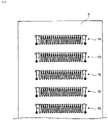
- the electric heater devices 10 in the first embodiment are provided for respective surfaces of the inner side wall 5, and are arranged in multiple stages in a vertical furnace length direction as illustrated in Fig. 8 .
- Each of the electric heater devices 10 has the same configuration.
- Fig. 2 is a partially enlarged view of Fig. 1 illustrating the electric heater device 10 and its periphery.
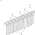
- Fig. 3 is a perspective view of the electric heater device 10, and
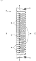
- Fig. 4 is a front view of the electric heater device 10.
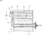
- Fig. 5 is a vertical sectional view illustrating a bar support 14 and its periphery of the electric heater device 10
- Fig. 6 is a vertical sectional view illustrating a hook 16 and its periphery of the electric heater device 10.
- the electric heater device 10 includes a bar 12, the bar support 14 ( Figs. 2 and 4 ), a plurality of the hooks 16, and an electric heater 18.
- the bar 12 is a rod-like member.
- the bar 12 is not limited to a rod shape having a circular cross section, and may have any shape such as a flat plate shape having a rectangular cross section.
- the bar 12 in the first embodiment extends in a straight line and has a hollow cylindrical shape.
- a material of the bar 12 is an insulating material such as ceramics.
- the bar 12 is supported by the bar supports 14.
- the bar support 14 is a member for supporting the bar 12 on the inner side wall 5. Two bar supports 14 are provided to support both end portions of the bar 12. A material of the bar support 14 is an insulating member such as a brick.
- the bar support 14 is attachable to and detachable from a tubular portion 20 provided on the inner side wall 5.
- the tubular portion 20 is reinforced by a triangular plate 21 ( Fig. 2 ) and welded to the inner side wall 5.
- Figs. 2 and 5 illustrate a state in which the bar support 14 is inserted into the tubular portion 20 of the inner side wall 5.
- the bar support 14 extends in a direction A toward an internal space of the heat treatment furnace 2 with being inserted into the tubular portion 20.
- the direction A in which the bar support 14 extends is upward at an angle ⁇ with respect to a horizontal direction H.
- the angle ⁇ is an acute angle.
- the bar support 14 has a recess 15 at its tip portion.
- the recess 15 is formed on an upper surface of the bar support 14 to receive the bar 12.
- Each of the end portions of the bar 12 is set in the recess 15 of the bar support 14 so that the bar 12 is supported by the bar supports 14.
- the hooks 16 are members suspended from the bar 12 to hook and support the electric heater 18.
- the plurality of hooks 16 are provided depending on a wave shape of the electric heater 18.
- the hooks 16 in the first embodiment are ring-shaped, and the bar 12 is passed through rings of the hooks 16.
- a shape of the hook 16 is not limited to a ring, and may be other shape such as an S shape as long as it can be suspended from the bar 12 to support the electric heater 18.
- the hook 16 in the first embodiment includes a main body 30, a shaft 32, and an insulator 34 made of ceramics.
- the main body 30 is a member that is engaged with the bar 12 to be suspended from the bar 12.
- the shaft 32 is a member that is passed through a hole of the insulator 34 and welded to the main body 30.
- the shaft 32 has a ring shape similarly to the main body 30.
- the insulator 34 is provided with a groove to support an upper end portion of the wave shape of the electric heater 18 from below.
- Passing the electric heater 18 through the ring-shaped hooks 16 from an end of the electric heater 18 in order can achieve easy disposition of the electric heater 18 in the rings of the hooks 16.
- the electric heater 18 is a heater of electric-heating to heat the object 6.
- the electric heater 18 in the first embodiment is an electric heating wire and has a rod shape (in other words, wire shape) made of metal (for example, a nichrome wire). As illustrated in Figs. 3 and 4 , the electric heater 18 has a wave shape, and each of upper end portions, which are folded portions, is hooked on the hook 16.
- the electric heater 18 is not limited to a rod-like heater, and may be a flat ribbon-like heater.
- both end portions of the electric heater 18 are connected (for example, welded) to the electrodes 22.
- the electrodes 22 are metal members for energizing the electric heater 18, and protrude from outside the heat treatment furnace 2 into the heat treatment furnace 2 through the furnace wall 4.
- the electrodes 22 are disposed below the tubular portions 20 in which the bar supports 14 are disposed.
- the both end portions of the electric heater 18 extend downward after being hooked on the upper surfaces of the bar supports 14, and are connected to the electrodes 22. According to such an arrangement, stress applied to the both end portions of the electric heater 18 is smaller than that in a case where the both end portions of the electric heater 18 are extended in the horizontal direction to be connected to the electrodes 22.
- the both end portions of the electric heater 18 may be wound around tips of the bar supports 14.
- the electric heater device 10 of the first embodiment is a device attached to the inner side wall 5 of the heat treatment furnace 2, and includes the bar 12, the bar support 14 for supporting an end portion of the bar 12 with the inner side wall 5, the plurality of hooks 16 suspended from the bar 12, and the electric heater 18 hooked and supported by the plurality of hooks 16.
- carrying the electric heater 18 into the heat treatment furnace 2 in a state of being hooked on the plurality of hooks 16 suspended from the bar 12 can perform attachment of the electric heater device 10 to the inner side wall 5 merely by placing the bar 12 onto the bar support 14.
- assembling operation of the electric heater device 10 outside the furnace arrangement operation of another electric heater device 10 in the furnace can be simultaneously performed, and thus construction period can be reduced.
- shortening work time in the furnace as an aerial work also leads to a reduction in risk of dangerous work. In this manner, installation work of the electric heater device 10 can be easy.
- the bar support 14 is attachable to and detachable from the tubular portion 20 of the inner side wall 5. According to such a configuration, replacement and repair of the bar support 14 are easy.
- the bar support 14 protrudes inward of the heat treatment furnace 2 at an upward angle with respect to the horizontal direction H with being disposed in the tubular portion 20. According to such a configuration, the bar support 14 can be made difficult to come off from the tubular portion 20.
- the electric heater device 10 of the first embodiment further includes the electrode 22 which protrudes from the inner side wall 5 at a position lower than the bar support 14 and to which an end portion of the electric heater 18 is connected.
- the electric heater 18 is hooked along the upper surface of the bar support 14 and then extends downward toward the electrode 22. According to such a configuration, as compared with a case where the end portion of the electric heater 18 is extended in the horizontal direction and connected to the electrode 22, a stress generated at the end portion can be reduced, and deformation and damage of the end portion can be suppressed. Thus, the electric heater 18 can be accurately connected to the electrode 22.
- the inner side wall 5 has a rectangular shape in a plan view, and the bar 12 extends linearly along the linear inner side wall 5.
- the bar 12 of a general-purpose member can be used, and thus the manufacturing cost of the electric heater device 10 can be reduced.
- the heat treatment furnace 2 of the first embodiment includes the electric heater device 10 described above and the inner side wall 5 to which the electric heater device 10 is attached. According to such a configuration, an effect similar to that of the electric heater device 10 described above can be obtained.
- an electric heater device 106 may be attached to a furnace wall 102 via through-holes 104 provided in the furnace wall 102 with a bar 108 of the electric heater device 106 being inserted into the through-holes 104.
- the electric heater device 106 can be supported by the furnace wall 102 while omitting the bar supports 14 as in the first embodiment, thereby achieving simple configuration.
- the through-holes 104 provided in the furnace wall 102 functions as the "bar supports".
- a gap between the through-hole 104 and the bar 108 may be closed by a separate means, for example, by filling a heat insulating material.
- the inner side wall 5 has a rectangular shape in a plan view in the first embodiment, the present disclosure is not limited to such a case.
- the inner side wall 5 may have, for example, a circular shape as illustrated in Fig. 9 .
- a bar having a gently curved shape may be used instead of the linear bar 12 of the first embodiment.
- a furnace wall 204 is formed in an arc shape, and has an inner side wall 205 having a circular cross-sectional shape.
- Bars 212 of an electric heater device 210 extend in an arc shape along the inner side wall 205.
- the bars 212 are supported by first bar supports 214A and second bar supports 214B.
- Each of the first bar supports 214A is a brick support to support two end portions close to each other of two bars 212
- each of the second bar supports 214B is a brick support to support an intermediate portion of one bar 212.
- Using the first bar support 214A for the two bars 212 leads to an efficient configuration.
- providing the second bar support 214B in addition to the first bar support 214A can support the bar 212 stably with restricting rotation of the bar 212, as compared with a configuration in which only the both end portions of the bar 212 are supported by the first bar supports 214A.
- the present disclosure is applicable to any electric heater device attached to an inner side wall of a heat treatment furnace, and to any heat treatment furnace provided with the electric heater device.
Landscapes
- Engineering & Computer Science (AREA)
- Mechanical Engineering (AREA)
- General Engineering & Computer Science (AREA)
- Furnace Details (AREA)
- Resistance Heating (AREA)
- Heating, Cooling, Or Curing Plastics Or The Like In General (AREA)
- Yarns And Mechanical Finishing Of Yarns Or Ropes (AREA)
Applications Claiming Priority (2)
| Application Number | Priority Date | Filing Date | Title |
|---|---|---|---|
| JP2020025454A JP6795715B1 (ja) | 2020-02-18 | 2020-02-18 | 電熱ヒータ装置およびそれを備える熱処理炉 |
| PCT/JP2020/047999 WO2021166430A1 (ja) | 2020-02-18 | 2020-12-22 | 電熱ヒータ装置およびそれを備える熱処理炉 |
Publications (2)
| Publication Number | Publication Date |
|---|---|
| EP4109022A1 true EP4109022A1 (de) | 2022-12-28 |
| EP4109022A4 EP4109022A4 (de) | 2024-02-21 |
Family
ID=73544837
Family Applications (1)
| Application Number | Title | Priority Date | Filing Date |
|---|---|---|---|
| EP20920315.7A Pending EP4109022A4 (de) | 2020-02-18 | 2020-12-22 | Elektrische heizvorrichtung und damit versehener wärmebehandlungsofen |
Country Status (5)
| Country | Link |
|---|---|
| EP (1) | EP4109022A4 (de) |
| JP (1) | JP6795715B1 (de) |
| CN (1) | CN115135944A (de) |
| TW (1) | TWI821622B (de) |
| WO (1) | WO2021166430A1 (de) |
Families Citing this family (1)
| Publication number | Priority date | Publication date | Assignee | Title |
|---|---|---|---|---|
| CN115930609B (zh) * | 2023-01-09 | 2026-03-24 | 拉普拉斯(无锡)半导体科技有限公司 | 多炉体结构 |
Family Cites Families (21)
| Publication number | Priority date | Publication date | Assignee | Title |
|---|---|---|---|---|
| GB241897A (en) * | 1924-10-23 | 1926-06-03 | British Thomson Houston Co Ltd | Improvements in and relating to electric furnaces |
| GB308818A (en) * | 1928-03-29 | 1930-06-05 | Gen Electric | Improvements in and relating to means for supporting heating coils in electric ovens |
| FR1078639A (fr) * | 1953-04-03 | 1954-11-19 | Heurtey & Cie | Dispositif d'accrochage notamment pour les éléments de chauffage à résistances dans les fours |
| GB1072931A (en) * | 1963-04-01 | 1967-06-21 | Ass Elect Ind | Improvements in or relating to electric furnaces |
| US4154975A (en) * | 1977-03-04 | 1979-05-15 | Sauder Industries, Inc. | Method and apparatus for supporting electric heating elements in a furnace insulated with ceramic fiber |
| US4233468A (en) * | 1978-12-01 | 1980-11-11 | Northup Jr John A | Holder attachment for use with furnace hardware |
| AU7112881A (en) * | 1981-05-28 | 1982-12-02 | Peter John Riley | Apparatus for supporting electric heating elements |
| US4403329A (en) * | 1981-07-06 | 1983-09-06 | General Signal Corporation | Support system for electrical resistance element |
| US4418415A (en) * | 1982-03-08 | 1983-11-29 | Kennecott Corporation | Ceramic fiber insulated furnaces with electrical hanger element of great mechanical integrity |
| US4443881A (en) * | 1982-06-01 | 1984-04-17 | Northcutt Donald R | Suspension system for electric heating elements |
| JPS6045367U (ja) | 1983-09-07 | 1985-03-30 | 新日本製鐵株式会社 | 竪形連続焼鈍炉の炉壁構造 |
| JPS6056025A (ja) | 1983-09-07 | 1985-04-01 | Nippon Steel Corp | 連続焼鈍炉の炉壁構造 |
| US4620309A (en) * | 1985-03-29 | 1986-10-28 | Ppg Industries, Inc. | Electric furnace construction |
| SU1332130A2 (ru) * | 1985-09-02 | 1987-08-23 | Предприятие П/Я В-2595 | Электропечь сопротивлени |
| JPS62163895A (ja) | 1986-01-14 | 1987-07-20 | Mitsubishi Heavy Ind Ltd | 船尾バルブ付き二重反転プロペラ装備船 |
| DE8808799U1 (de) * | 1988-07-08 | 1988-09-29 | Didier-Werke Ag, 6200 Wiesbaden | Befestigungseinrichtung für elektrische Heizleiter |
| SU1740939A1 (ru) * | 1989-06-26 | 1992-06-15 | Харьковский Филиал Всесоюзного Научно-Исследовательского, Проектно-Конструкторского И Технологического Электротермического Оборудования | Способ креплени нагревателей в электропечи |
| JP2707195B2 (ja) | 1993-01-22 | 1998-01-28 | 新日本製鐵株式会社 | 繊維質耐火材ブロック |
| JP4542358B2 (ja) | 2004-03-29 | 2010-09-15 | 新日鉄エンジニアリング株式会社 | 連続焼鈍炉用繊維質耐火材ブロック |
| JP4769842B2 (ja) | 2008-04-08 | 2011-09-07 | 株式会社アルファ・オイコス | 高温用加熱炉 |
| CN205648027U (zh) * | 2016-05-03 | 2016-10-12 | 洛阳Lyc轴承有限公司 | 一种防止短路的电热辐射管 |
-
2020
- 2020-02-18 JP JP2020025454A patent/JP6795715B1/ja active Active
- 2020-12-22 WO PCT/JP2020/047999 patent/WO2021166430A1/ja not_active Ceased
- 2020-12-22 EP EP20920315.7A patent/EP4109022A4/de active Pending
- 2020-12-22 CN CN202080096790.1A patent/CN115135944A/zh active Pending
- 2020-12-25 TW TW109146166A patent/TWI821622B/zh active
Also Published As
| Publication number | Publication date |
|---|---|
| EP4109022A4 (de) | 2024-02-21 |
| JP6795715B1 (ja) | 2020-12-02 |
| JP2021131171A (ja) | 2021-09-09 |
| TW202132741A (zh) | 2021-09-01 |
| WO2021166430A1 (ja) | 2021-08-26 |
| CN115135944A (zh) | 2022-09-30 |
| TWI821622B (zh) | 2023-11-11 |
Similar Documents
| Publication | Publication Date | Title |
|---|---|---|
| JP6795715B1 (ja) | 電熱ヒータ装置およびそれを備える熱処理炉 | |
| US20160203970A1 (en) | Halogen lamp | |
| US4443881A (en) | Suspension system for electric heating elements | |
| EP3133362A1 (de) | Wärmebehandlungsvorrichtung | |
| CN218238439U (zh) | 用于隔焰加热炉的自身预热烧嘴辐射管装置 | |
| CN105466224A (zh) | 一种加热炉 | |
| KR200328000Y1 (ko) | 로터 행거 | |
| JP2020029995A (ja) | 熱処理装置 | |
| JPH0625836Y2 (ja) | 熱処理炉のヒータ支持部材 | |
| CN205843367U (zh) | 电阻带悬吊安装结构 | |
| CN210141942U (zh) | 一种真空热处理炉测试装置安装结构 | |
| JP2005093746A (ja) | 熱処理炉 | |
| CN216694489U (zh) | 一种陶瓷纤维模块的加热丝固定装置 | |
| JP2008180424A (ja) | 加熱炉のバッフル上部吊棒の固定方法及び固定構造 | |
| CN222540831U (zh) | 真空热处理炉用改进型不易脱落加热元件背部绝缘装置 | |
| CN212893465U (zh) | 一种细长料吊运专用机构 | |
| CN218162892U (zh) | 一种加热灯管支撑装置 | |
| CN223228391U (zh) | 一种角管锅炉水冷壁固定限位结构 | |
| JP2024087630A (ja) | 加熱炉 | |
| CN212178993U (zh) | 一种具有防抖支架的壁挂炉 | |
| CN210974926U (zh) | 一种方便拆卸安装的单晶炉底部加热器 | |
| CN202809007U (zh) | 一种晶体生长炉用发热装置及刚玉单晶生长炉 | |
| JPWO2011010622A1 (ja) | ハンガー組立体およびフロート板ガラス製造装置 | |
| CN103512371B (zh) | 一种加热器固定装置 | |
| CN207894254U (zh) | 电炉电极更换用装置 |
Legal Events
| Date | Code | Title | Description |
|---|---|---|---|
| STAA | Information on the status of an ep patent application or granted ep patent |
Free format text: STATUS: THE INTERNATIONAL PUBLICATION HAS BEEN MADE |
|
| PUAI | Public reference made under article 153(3) epc to a published international application that has entered the european phase |
Free format text: ORIGINAL CODE: 0009012 |
|
| STAA | Information on the status of an ep patent application or granted ep patent |
Free format text: STATUS: REQUEST FOR EXAMINATION WAS MADE |
|
| 17P | Request for examination filed |
Effective date: 20220708 |
|
| AK | Designated contracting states |
Kind code of ref document: A1 Designated state(s): AL AT BE BG CH CY CZ DE DK EE ES FI FR GB GR HR HU IE IS IT LI LT LU LV MC MK MT NL NO PL PT RO RS SE SI SK SM TR |
|
| DAV | Request for validation of the european patent (deleted) | ||
| DAX | Request for extension of the european patent (deleted) | ||
| A4 | Supplementary search report drawn up and despatched |
Effective date: 20240124 |
|
| RIC1 | Information provided on ipc code assigned before grant |
Ipc: F27D 1/00 20060101ALI20240118BHEP Ipc: F27B 5/14 20060101ALI20240118BHEP Ipc: F27D 11/02 20060101AFI20240118BHEP |
|
| STAA | Information on the status of an ep patent application or granted ep patent |
Free format text: STATUS: EXAMINATION IS IN PROGRESS |
|
| 17Q | First examination report despatched |
Effective date: 20241121 |
|
| GRAP | Despatch of communication of intention to grant a patent |
Free format text: ORIGINAL CODE: EPIDOSNIGR1 |
|
| STAA | Information on the status of an ep patent application or granted ep patent |
Free format text: STATUS: GRANT OF PATENT IS INTENDED |