EP4109025A2 - Dispositif doté d'un récipient destiné à recevoir de l'eau et à être installé dans le sol, ainsi que pourvu d'échangeurs de chaleur - Google Patents
Dispositif doté d'un récipient destiné à recevoir de l'eau et à être installé dans le sol, ainsi que pourvu d'échangeurs de chaleur Download PDFInfo
- Publication number
- EP4109025A2 EP4109025A2 EP22180587.2A EP22180587A EP4109025A2 EP 4109025 A2 EP4109025 A2 EP 4109025A2 EP 22180587 A EP22180587 A EP 22180587A EP 4109025 A2 EP4109025 A2 EP 4109025A2
- Authority
- EP
- European Patent Office
- Prior art keywords
- air
- heat exchanger
- container
- air inlet
- air outlet
- Prior art date
- Legal status (The legal status is an assumption and is not a legal conclusion. Google has not performed a legal analysis and makes no representation as to the accuracy of the status listed.)
- Pending
Links
Images

Classifications
-
- F—MECHANICAL ENGINEERING; LIGHTING; HEATING; WEAPONS; BLASTING
- F28—HEAT EXCHANGE IN GENERAL
- F28D—HEAT-EXCHANGE APPARATUS, NOT PROVIDED FOR IN ANOTHER SUBCLASS, IN WHICH THE HEAT-EXCHANGE MEDIA DO NOT COME INTO DIRECT CONTACT
- F28D20/00—Heat storage plants or apparatus in general; Regenerative heat-exchange apparatus not covered by groups F28D17/00 or F28D19/00
- F28D20/0034—Heat storage plants or apparatus in general; Regenerative heat-exchange apparatus not covered by groups F28D17/00 or F28D19/00 using liquid heat storage material
- F28D20/0043—Heat storage plants or apparatus in general; Regenerative heat-exchange apparatus not covered by groups F28D17/00 or F28D19/00 using liquid heat storage material specially adapted for long-term heat storage; Underground tanks; Floating reservoirs; Pools; Ponds
-
- F—MECHANICAL ENGINEERING; LIGHTING; HEATING; WEAPONS; BLASTING
- F24—HEATING; RANGES; VENTILATING
- F24F—AIR-CONDITIONING; AIR-HUMIDIFICATION; VENTILATION; USE OF AIR CURRENTS FOR SCREENING
- F24F1/00—Room units for air-conditioning, e.g. separate or self-contained units or units receiving primary air from a central station
- F24F1/06—Separate outdoor units, e.g. outdoor unit to be linked to a separate room comprising a compressor and a heat exchanger
- F24F1/14—Heat exchangers specially adapted for separate outdoor units
-
- F—MECHANICAL ENGINEERING; LIGHTING; HEATING; WEAPONS; BLASTING
- F24—HEATING; RANGES; VENTILATING
- F24F—AIR-CONDITIONING; AIR-HUMIDIFICATION; VENTILATION; USE OF AIR CURRENTS FOR SCREENING
- F24F1/00—Room units for air-conditioning, e.g. separate or self-contained units or units receiving primary air from a central station
- F24F1/06—Separate outdoor units, e.g. outdoor unit to be linked to a separate room comprising a compressor and a heat exchanger
- F24F1/60—Arrangement or mounting of the outdoor unit
-
- F—MECHANICAL ENGINEERING; LIGHTING; HEATING; WEAPONS; BLASTING
- F24—HEATING; RANGES; VENTILATING
- F24F—AIR-CONDITIONING; AIR-HUMIDIFICATION; VENTILATION; USE OF AIR CURRENTS FOR SCREENING
- F24F1/00—Room units for air-conditioning, e.g. separate or self-contained units or units receiving primary air from a central station
- F24F1/06—Separate outdoor units, e.g. outdoor unit to be linked to a separate room comprising a compressor and a heat exchanger
- F24F1/60—Arrangement or mounting of the outdoor unit
- F24F1/66—Arrangement or mounting of the outdoor unit under the floor level
-
- F—MECHANICAL ENGINEERING; LIGHTING; HEATING; WEAPONS; BLASTING
- F24—HEATING; RANGES; VENTILATING
- F24F—AIR-CONDITIONING; AIR-HUMIDIFICATION; VENTILATION; USE OF AIR CURRENTS FOR SCREENING
- F24F5/00—Air-conditioning systems or apparatus not covered by F24F1/00 or F24F3/00, e.g. using solar heat or combined with household units such as an oven or water heater
- F24F5/0007—Air-conditioning systems or apparatus not covered by F24F1/00 or F24F3/00, e.g. using solar heat or combined with household units such as an oven or water heater cooling apparatus specially adapted for use in air-conditioning
- F24F5/0017—Air-conditioning systems or apparatus not covered by F24F1/00 or F24F3/00, e.g. using solar heat or combined with household units such as an oven or water heater cooling apparatus specially adapted for use in air-conditioning using cold storage bodies, e.g. ice
-
- F—MECHANICAL ENGINEERING; LIGHTING; HEATING; WEAPONS; BLASTING
- F24—HEATING; RANGES; VENTILATING
- F24V—COLLECTION, PRODUCTION OR USE OF HEAT NOT OTHERWISE PROVIDED FOR
- F24V50/00—Use of heat from natural sources, e.g. from the sea
-
- F—MECHANICAL ENGINEERING; LIGHTING; HEATING; WEAPONS; BLASTING
- F28—HEAT EXCHANGE IN GENERAL
- F28D—HEAT-EXCHANGE APPARATUS, NOT PROVIDED FOR IN ANOTHER SUBCLASS, IN WHICH THE HEAT-EXCHANGE MEDIA DO NOT COME INTO DIRECT CONTACT
- F28D1/00—Heat-exchange apparatus having stationary conduit assemblies for one heat-exchange medium only, the media being in contact with different sides of the conduit wall, in which the other heat-exchange medium is a large body of fluid, e.g. domestic or motor car radiators
- F28D1/02—Heat-exchange apparatus having stationary conduit assemblies for one heat-exchange medium only, the media being in contact with different sides of the conduit wall, in which the other heat-exchange medium is a large body of fluid, e.g. domestic or motor car radiators with heat-exchange conduits immersed in the body of fluid
- F28D1/0233—Heat-exchange apparatus having stationary conduit assemblies for one heat-exchange medium only, the media being in contact with different sides of the conduit wall, in which the other heat-exchange medium is a large body of fluid, e.g. domestic or motor car radiators with heat-exchange conduits immersed in the body of fluid with air flow channels
- F28D1/024—Heat-exchange apparatus having stationary conduit assemblies for one heat-exchange medium only, the media being in contact with different sides of the conduit wall, in which the other heat-exchange medium is a large body of fluid, e.g. domestic or motor car radiators with heat-exchange conduits immersed in the body of fluid with air flow channels with an air driving element
-
- F—MECHANICAL ENGINEERING; LIGHTING; HEATING; WEAPONS; BLASTING
- F28—HEAT EXCHANGE IN GENERAL
- F28D—HEAT-EXCHANGE APPARATUS, NOT PROVIDED FOR IN ANOTHER SUBCLASS, IN WHICH THE HEAT-EXCHANGE MEDIA DO NOT COME INTO DIRECT CONTACT
- F28D1/00—Heat-exchange apparatus having stationary conduit assemblies for one heat-exchange medium only, the media being in contact with different sides of the conduit wall, in which the other heat-exchange medium is a large body of fluid, e.g. domestic or motor car radiators
- F28D1/02—Heat-exchange apparatus having stationary conduit assemblies for one heat-exchange medium only, the media being in contact with different sides of the conduit wall, in which the other heat-exchange medium is a large body of fluid, e.g. domestic or motor car radiators with heat-exchange conduits immersed in the body of fluid
- F28D1/03—Heat-exchange apparatus having stationary conduit assemblies for one heat-exchange medium only, the media being in contact with different sides of the conduit wall, in which the other heat-exchange medium is a large body of fluid, e.g. domestic or motor car radiators with heat-exchange conduits immersed in the body of fluid with plate-like or laminated conduits
-
- F—MECHANICAL ENGINEERING; LIGHTING; HEATING; WEAPONS; BLASTING
- F28—HEAT EXCHANGE IN GENERAL
- F28D—HEAT-EXCHANGE APPARATUS, NOT PROVIDED FOR IN ANOTHER SUBCLASS, IN WHICH THE HEAT-EXCHANGE MEDIA DO NOT COME INTO DIRECT CONTACT
- F28D1/00—Heat-exchange apparatus having stationary conduit assemblies for one heat-exchange medium only, the media being in contact with different sides of the conduit wall, in which the other heat-exchange medium is a large body of fluid, e.g. domestic or motor car radiators
- F28D1/02—Heat-exchange apparatus having stationary conduit assemblies for one heat-exchange medium only, the media being in contact with different sides of the conduit wall, in which the other heat-exchange medium is a large body of fluid, e.g. domestic or motor car radiators with heat-exchange conduits immersed in the body of fluid
- F28D1/04—Heat-exchange apparatus having stationary conduit assemblies for one heat-exchange medium only, the media being in contact with different sides of the conduit wall, in which the other heat-exchange medium is a large body of fluid, e.g. domestic or motor car radiators with heat-exchange conduits immersed in the body of fluid with tubular conduits
- F28D1/0408—Multi-circuit heat exchangers, e.g. integrating different heat exchange sections in the same unit or heat exchangers for more than two fluids
- F28D1/0426—Multi-circuit heat exchangers, e.g. integrating different heat exchange sections in the same unit or heat exchangers for more than two fluids with units having particular arrangement relative to the large body of fluid, e.g. with interleaved units or with adjacent heat exchange units in common air flow or with units extending at an angle to each other or with units arranged around a central element
-
- F—MECHANICAL ENGINEERING; LIGHTING; HEATING; WEAPONS; BLASTING
- F28—HEAT EXCHANGE IN GENERAL
- F28D—HEAT-EXCHANGE APPARATUS, NOT PROVIDED FOR IN ANOTHER SUBCLASS, IN WHICH THE HEAT-EXCHANGE MEDIA DO NOT COME INTO DIRECT CONTACT
- F28D1/00—Heat-exchange apparatus having stationary conduit assemblies for one heat-exchange medium only, the media being in contact with different sides of the conduit wall, in which the other heat-exchange medium is a large body of fluid, e.g. domestic or motor car radiators
- F28D1/02—Heat-exchange apparatus having stationary conduit assemblies for one heat-exchange medium only, the media being in contact with different sides of the conduit wall, in which the other heat-exchange medium is a large body of fluid, e.g. domestic or motor car radiators with heat-exchange conduits immersed in the body of fluid
- F28D1/04—Heat-exchange apparatus having stationary conduit assemblies for one heat-exchange medium only, the media being in contact with different sides of the conduit wall, in which the other heat-exchange medium is a large body of fluid, e.g. domestic or motor car radiators with heat-exchange conduits immersed in the body of fluid with tubular conduits
- F28D1/053—Heat-exchange apparatus having stationary conduit assemblies for one heat-exchange medium only, the media being in contact with different sides of the conduit wall, in which the other heat-exchange medium is a large body of fluid, e.g. domestic or motor car radiators with heat-exchange conduits immersed in the body of fluid with tubular conduits the conduits being straight
- F28D1/0535—Heat-exchange apparatus having stationary conduit assemblies for one heat-exchange medium only, the media being in contact with different sides of the conduit wall, in which the other heat-exchange medium is a large body of fluid, e.g. domestic or motor car radiators with heat-exchange conduits immersed in the body of fluid with tubular conduits the conduits being straight the conduits having a non-circular cross-section
- F28D1/05366—Assemblies of conduits connected to common headers, e.g. core type radiators
-
- F—MECHANICAL ENGINEERING; LIGHTING; HEATING; WEAPONS; BLASTING
- F24—HEATING; RANGES; VENTILATING
- F24F—AIR-CONDITIONING; AIR-HUMIDIFICATION; VENTILATION; USE OF AIR CURRENTS FOR SCREENING
- F24F1/00—Room units for air-conditioning, e.g. separate or self-contained units or units receiving primary air from a central station
- F24F1/06—Separate outdoor units, e.g. outdoor unit to be linked to a separate room comprising a compressor and a heat exchanger
- F24F1/14—Heat exchangers specially adapted for separate outdoor units
- F24F1/16—Arrangement or mounting thereof
-
- F—MECHANICAL ENGINEERING; LIGHTING; HEATING; WEAPONS; BLASTING
- F24—HEATING; RANGES; VENTILATING
- F24F—AIR-CONDITIONING; AIR-HUMIDIFICATION; VENTILATION; USE OF AIR CURRENTS FOR SCREENING
- F24F1/00—Room units for air-conditioning, e.g. separate or self-contained units or units receiving primary air from a central station
- F24F1/06—Separate outdoor units, e.g. outdoor unit to be linked to a separate room comprising a compressor and a heat exchanger
- F24F1/14—Heat exchangers specially adapted for separate outdoor units
- F24F1/18—Heat exchangers specially adapted for separate outdoor units characterised by their shape
-
- F—MECHANICAL ENGINEERING; LIGHTING; HEATING; WEAPONS; BLASTING
- F24—HEATING; RANGES; VENTILATING
- F24F—AIR-CONDITIONING; AIR-HUMIDIFICATION; VENTILATION; USE OF AIR CURRENTS FOR SCREENING
- F24F5/00—Air-conditioning systems or apparatus not covered by F24F1/00 or F24F3/00, e.g. using solar heat or combined with household units such as an oven or water heater
- F24F5/0007—Air-conditioning systems or apparatus not covered by F24F1/00 or F24F3/00, e.g. using solar heat or combined with household units such as an oven or water heater cooling apparatus specially adapted for use in air-conditioning
- F24F5/0017—Air-conditioning systems or apparatus not covered by F24F1/00 or F24F3/00, e.g. using solar heat or combined with household units such as an oven or water heater cooling apparatus specially adapted for use in air-conditioning using cold storage bodies, e.g. ice
- F24F2005/0025—Air-conditioning systems or apparatus not covered by F24F1/00 or F24F3/00, e.g. using solar heat or combined with household units such as an oven or water heater cooling apparatus specially adapted for use in air-conditioning using cold storage bodies, e.g. ice using heat exchange fluid storage tanks
-
- F—MECHANICAL ENGINEERING; LIGHTING; HEATING; WEAPONS; BLASTING
- F24—HEATING; RANGES; VENTILATING
- F24F—AIR-CONDITIONING; AIR-HUMIDIFICATION; VENTILATION; USE OF AIR CURRENTS FOR SCREENING
- F24F5/00—Air-conditioning systems or apparatus not covered by F24F1/00 or F24F3/00, e.g. using solar heat or combined with household units such as an oven or water heater
- F24F5/0007—Air-conditioning systems or apparatus not covered by F24F1/00 or F24F3/00, e.g. using solar heat or combined with household units such as an oven or water heater cooling apparatus specially adapted for use in air-conditioning
- F24F5/0017—Air-conditioning systems or apparatus not covered by F24F1/00 or F24F3/00, e.g. using solar heat or combined with household units such as an oven or water heater cooling apparatus specially adapted for use in air-conditioning using cold storage bodies, e.g. ice
- F24F2005/0032—Systems storing energy during the night
-
- F—MECHANICAL ENGINEERING; LIGHTING; HEATING; WEAPONS; BLASTING
- F28—HEAT EXCHANGE IN GENERAL
- F28D—HEAT-EXCHANGE APPARATUS, NOT PROVIDED FOR IN ANOTHER SUBCLASS, IN WHICH THE HEAT-EXCHANGE MEDIA DO NOT COME INTO DIRECT CONTACT
- F28D20/00—Heat storage plants or apparatus in general; Regenerative heat-exchange apparatus not covered by groups F28D17/00 or F28D19/00
- F28D2020/0065—Details, e.g. particular heat storage tanks, auxiliary members within tanks
- F28D2020/0078—Heat exchanger arrangements
Definitions
- the present invention relates to a device with a container for holding water and for installation in the ground, with a water heat exchanger arranged in the container with an air heat exchanger arranged at least partially in the container, with at least one air inlet for supplying air from the environment to the air heat exchanger and with at least an air outlet for discharging the air from the air heat exchanger to the environment.
- So-called pumped-storage power plants for example, have proven themselves for this purpose.
- water e.g. with the help of electricity generated by wind turbines, is pumped into a higher reservoir. If energy is required, the potential energy of the water when it is drained into a lower storage basin can be used to drive generators and thus generate electricity.
- the object of the present invention is to create an efficient device for storing energy.
- a device with a container for holding water and for installation in the ground is proposed.
- the container may be artificial and/or natural.
- the device also includes a water heat exchanger arranged in the container. With the help of the water heat exchanger, thermal energy can be transferred to the water and thermal energy can be extracted from the water. In this way, the thermal energy can be temporarily stored in the water in order to be able to extract the thermal energy again at a later point in time, for example to heat a building.
- the device comprises an air heat exchanger arranged at least partially in the container.
- the air heat exchanger With the help of the air heat exchanger, heat energy can be given off to the air and heat energy can be extracted from the air.
- the water heat exchanger can be at least partially immersed in the water after it has been inserted, so that a heat transfer medium flowing through the water heat exchanger is in heat-conducting contact with the water via one or more heat exchanger walls, in order to enable an exchange of thermal energy between the heat transfer medium and the water make possible.
- the water heat exchanger can also be completely submerged, so that the water heat exchanger comes into full contact with the water.
- a heat carrier can also flow through the air heat exchanger in order to also exchange thermal energy with the air.
- the device has at least one air inlet for supplying air from the environment to the air heat exchanger. Furthermore, the device has at least one air outlet for discharging the air from the air heat exchanger to the environment.
- the air heat exchanger is in contact with the air in the environment via the air inlet and the air outlet.
- air circulation can be generated between the air heat exchanger and the environment in order to either transport heat energy away from the air heat exchanger or to conduct heat energy to the air heat exchanger.
- cold and warm air is introduced or discharged via the air inlet and the air outlet, depending on whether heat energy is transferred from the air heat exchanger to the air or heat energy is transferred from the air to the air heat exchanger.
- the air heat exchanger can be used to extract thermal energy from the air, for example to heat a building.
- the at least one air inlet is arranged and/or designed in such a way that the air from the environment can be fed to the air heat exchanger from above the device.
- the at least one air outlet is arranged and/or designed in such a way that the air can be discharged from the air heat exchanger to the environment on the side of the device. If the air heat exchanger is operated in such a way that thermal energy is extracted from the ambient air, for example to heat a building, warm air is supplied from above the device via the at least one air inlet to the air heat exchanger. The air heat exchanger extracts thermal energy from this air, which cools it down.
- the now cold air is then discharged away from the air heat exchanger to the environment via the at least one air outlet on the side of the device.
- the now cold air from which thermal energy has already been extracted, can be prevented from getting back to the at least one air inlet, via which the cold air would be fed back to the air heat exchanger.
- the cold air since the cold air has a higher density than correspondingly warmer air, the cold air flows along the floor away from the device until the cold air mixes with the ambient air.
- the device can be operated more effectively since fresh air is guided from above the device to the air heat exchanger and the used air or the air from which thermal energy has been extracted is guided away to the side of the device. This prevents the cold air from returning to the air intake. An efficiency of the device is thereby improved or increased.
- the device can also be used to heat a building, preferably in summer cool.
- the heat carrier For example, a heat pump is operated in such a way that it transfers thermal energy from the structure to the heat transfer medium, so that the latter has a temperature that is above the water temperature.
- the heat energy is transferred to the water, which can heat up as a result.
- the thermal energy is now also temporarily stored in the water, at least for a certain period of time. In the meantime, the heat transfer medium has cooled down and is being transported back to the building.
- the at least one air outlet is designed to direct the discharged air away from the air inlet. This also prevents the air that has been deprived of thermal energy and is therefore colder from returning to the air intake. The recirculation of the air to the air inlet after it has left the air outlet can hereby be prevented.
- the air inlet is arranged higher than the air outlet when the device is installed. Air that has been deprived of thermal energy has cooled down and is therefore more dense on than correspondingly warmer air. As a result, the colder air sinks to the ground by itself.
- the said arrangement of the air inlet to the air outlet can thus prevent the cold air from getting back to the air inlet.
- the air inlet is arranged on a front side of the device.
- the end face is the side that protrudes from the ground when the device is installed.
- the air inlet is thus arranged at the top of the device, so that the air can be routed directly from above to the air heat exchanger.
- the air inlet can also be arranged in a central area of the end face. This places the air intake furthest from the sides of the device where the cold air is exhausted from the device.
- the at least one air outlet is arranged on a peripheral side of the device.
- the air discharged from the air outlet can be discharged directly to the side.
- the at least one air outlet can be arranged on the end face, in particular in an edge area. Since the cold air has a higher density when heat energy has been extracted from it, it sinks to the ground. If the at least one air inlet is arranged on the front side, in particular in the edge region, this air flows away of its own accord from the front side and in particular down over an edge of the device.
- the at least one air outlet is arranged above ground level when the device is installed. Due to the higher density of the air, when thermal energy has been extracted from it, it sinks to the ground and consequently away from the at least one air outlet.
- at least part of the air heat exchanger is installed above a is arranged at ground level. This also causes the cold, denser air to flow away from the air heat exchanger when air has been extracted from it. As a result, a natural air flow can be formed.
- the device for covering the air inlet has at least one covering element.
- the at least one cover element can protrude laterally beyond the air inlet. This can prevent, for example, rainwater or leaves or the like from getting into the air inlet.
- the device has a container cover which closes the container at the end face, with the at least one air inlet being arranged in the container cover.
- the air outlet is formed in a container wall and/or has and/or forms at least one air outlet opening.
- the at least one air outlet opening of the air outlet is therefore preferably formed in the container wall.
- an air inlet opening of the at least one air inlet is closed by means of a shut-off element. Additionally or alternatively, it is advantageous if the at least one air outlet is closed with at least one shut-off element. Additionally or alternatively, it is advantageous if the air outlet and/or the at least one air outlet opening is closed with the at least one shut-off element. In this case, the at least one air outlet can also be closed with the shut-off element. With the aid of the at least one blocking element, smaller animals, such as mice, martens or cats, and/or people can be prevented from entering the device. However, the shut-off element is still permeable to air, so that the air flow only little disabled.
- the at least one blocking element blocks only animals and/or people from accessing the interior of the device through the at least one air inlet or through the corresponding air inlet opening and/or through the at least one air outlet and/or through the air outlet opening.
- the shut-off element can also be designed, for example, as a lattice, which preferably comprises rods that are parallel to one another and are preferably made of metal. These bars can be arranged in a vertical, diagonal and/or horizontal direction. Furthermore, the grid can have crossing bars.
- the shut-off element can also be designed as a gate, as a perforated plate and/or as a mesh, in particular as a wire mesh.
- the shut-off element can cover the at least one air inlet or the corresponding air inlet opening and/or the at least one air outlet or the corresponding air outlet opening.
- the shut-off element can also be arranged in the air inlet and/or the air outlet opening.
- the container in particular the container lid, has a projection which protrudes laterally beyond the air outlet and/or beyond the container wall of the container. Additionally or alternatively, the projection can also extend laterally over the at least one air outlet opening. Furthermore, additionally or alternatively, the projection can also extend laterally over the blocking element that blocks the at least one air outlet or the air outlet opening.
- the at least one air outlet can be covered from above with the aid of the projection. This makes it difficult for the exiting cold air, once heat energy has been extracted from it, to get back to the air intake.
- the projection can be used to prevent rain, for example, from getting into the at least one air outlet or onto the shut-off element. Since cold air escapes here, there is a risk that the rain will freeze on the shut-off element and the air flow will be obstructed.
- the projection forms the shape of a roof for the at least one air outlet.
- the projection extends completely along the peripheral side. As a result, the peripheral side is completely covered by the projection. This also simplifies a construction of the device.
- the device has a fan, by means of which the air can be sucked into the air inlet. Additionally or alternatively, the air can be blown out via the air outlet by means of the fan. With the aid of the fan, an air flow can be formed which advantageously guides the air through the device and through the air heat exchanger. This can also increase the amount of air that is led to and discharged from the air heat exchanger.
- the fan is arranged in the area of the air inlet.
- warm air is fed to the air heat exchanger and, in comparison, cold air is drawn out of the air heat exchanger. Warm air is thus guided through the air inlet and the cold air through the air outlet. If the fan is arranged in the area of the air inlet, this can prevent the fan from icing up due to the warm or warmer air.
- a device with a container for receiving water and for installation in the ground is also proposed.
- the device can have at least one feature of the preceding and/or the following description.
- the same or identically named features can also have the same effects or have the same effect.
- the device has a water heat exchanger arranged in the container. With the help of the water heat exchanger, heat energy can be transferred to the water or removed from the water, for example in order to store the heat energy in it, or to heat the heat energy which previously saved, for example, to heat a building, for example.
- the device also has an air heat exchanger which is at least partially arranged in the container. Heat energy can also be transferred to the air or extracted from the air by means of the air heat exchanger. For example, thermal energy can be transported away from the building to cool it. The thermal energy is released into the air. In addition, thermal energy can be extracted from the air in order to heat the building.
- the air heat exchanger has an interior space and at least one side wall delimiting the interior space, air being able to flow through at least some areas of the side wall in order to exchange thermal energy.
- the air from which thermal energy is withdrawn or to which the thermal energy is transferred thus flows through the side wall and in the process transfers the thermal energy to the air heat exchanger or absorbs it from the air heat exchanger.
- At least one section of the side wall is formed by at least one plate heat exchanger.
- the at least one plate heat exchanger is flat and/or curved.
- the corresponding shape of the plate heat exchanger can be used.
- the air heat exchanger has the shape of a polygon, with at least one side of the polygon being at least partially is formed by the plate heat exchanger.
- the air heat exchanger can be formed in a simple way by, in particular, flat plate heat exchangers.
- the plate heat exchangers are arranged in relation to one another, for example in accordance with the polygon.
- the air heat exchanger comprises at least three plate heat exchangers, which are arranged in a top view in such a way that they form at least areas of the sides of the corresponding polygon.
- the interior can be formed in a simple manner with the aid of the three plate heat exchangers, so that the air can flow from the interior to the outside of the air heat exchanger or from outside the air heat exchanger to the interior.
- the plate heat exchangers adjoin one another in the corners of the corresponding polygon. This allows a closed polygon to be formed. This is important in that the air cannot flow past the air heat exchanger or the plate heat exchanger through gaps or gaps.
- connecting elements preferably connecting the plate heat exchangers to one another in an airtight manner. This also ensures that the air always flows through the air heat exchanger or the plate heat exchanger.
- the plate heat exchangers are arranged in a regular or irregular polygon.
- a device with a container for holding water and for installation in the ground is proposed.
- the device can have at least one feature of the preceding and/or the following description.
- the same or identical features compared to the previous and/or following description can also have the same effects or have the same effect, unless otherwise stated.
- the container has an assembly opening through which the elements of the device are at least partially arranged in the container.
- the device comprises a heat exchanger unit that can be introduced into the container via the assembly opening.
- the heat exchanger unit has a water heat exchanger, with the help of which thermal energy can be transferred to the water or extracted from the water, for example in order to store the thermal energy therein, or to extract the thermal energy which was previously stored, for example in order to heat a building, for example .
- the heat exchanger unit also has an air heat exchanger, by means of which thermal energy can also be transferred to the air and extracted from the air.
- thermal energy can be transported away from the building to cool it. The thermal energy is released into the air.
- thermal energy can be extracted from the air in order to heat the building.
- the heat exchanger unit includes a frame accommodating the water heat exchanger and the air heat exchanger.
- the water heat exchanger and the air heat exchanger can be positioned relative to one another and/or combined by means of the frame.
- the heat exchanger unit comprises laterally protruding assembly extensions, by means of which the heat exchanger unit can be hung on the container in the region of the assembly opening, so that the heat exchanger unit hovers over a container floor of the container in the assembled state.
- the heat exchanger unit can be spaced apart from the container, except for the area in which the mounting projections are in contact with the container.
- the container has a sealing film on its inside, which preferably extends over the bottom and/or at least partially over an inner wall of the container.
- the container can be sealed with the help of the sealing foil. The stated spacing of the heat exchanger unit from the container (apart from the areas of the assembly extensions) prevents damage to the sealing foil.
- the mounting extensions are formed on the frame. This means that the heat exchanger unit can be hung in directly when it is inserted into the container through the assembly opening. Additionally or alternatively, the mounting extensions can be hung on a container edge of the container. This eliminates the need for additional elements, since the edge of the container, which is already present, is used for hanging.
- figure 1 shows a device 1 with a container 2 for receiving water 3 and for installation in the ground 4.
- the device 1 and the container 2 can be installed in the ground 4 or in the ground in order to arrange the device 1 in a space-saving manner.
- the device 1 comprises a water heat exchanger 5 arranged in the container 2 .
- Thermal energy can be exchanged with the water 3 with the water heat exchanger 5 .
- thermal energy can be supplied to the water in order to temporarily store it in the water 3, for example, or to cool a building (not shown here).
- thermal energy can also be extracted from the water 3 with the aid of the water heat exchanger 5 in order to heat a building.
- the water heat exchanger 5 preferably has a heat carrier, for example glycol, flowing through it.
- the device 1 has an air heat exchanger 6 which is arranged at least partially in the container 2 .
- Thermal energy can be exchanged with the air 7 with the aid of the air heat exchanger 6 .
- a building can also be cooled in this way if thermal energy is released into the air 7 .
- the building can be heated if the thermal energy is extracted from the air 7 .
- the water heat exchanger 5 as well as the air heat exchanger 6 can furthermore each have an inlet or outlet, not shown here, for the respective heat transfer medium, which are preferably formed by means of lines.
- a total of four lines can lead to the device 1, where two lines are inlets and two lines are outlets. These lines can be routed at least partially through the ground 4 .
- the device 1 comprises at least one air inlet 8 for supplying air 7 from the environment 28 to the air heat exchanger 6.
- the device 1 comprises at least one air outlet 9 for discharging the air 7 from the air heat exchanger 6 into the environment 28.
- the at least one air inlet 8 is arranged and/or designed on the device 1 and/or on the container 2 in such a way that the air 7 from the environment 28 can be fed to the air heat exchanger 6 from above the device 1 .
- the device 1 is in the figure 1 installed in the ground 4 as planned.
- the air heat exchanger 6 is above the water heat exchanger 7, since there is water 3 in the container 2 and this naturally collects in the lower area.
- the at least one air outlet 9 is arranged and/or designed on the device 1 and/or the container 2 in such a way that the air can be discharged from the air heat exchanger 6 to the surroundings 28 on the side of the device 1 . If thermal energy is extracted from the air 7 by means of the air heat exchanger 6, the air 7 cools down to such an extent that it is colder than the air 7 of the surroundings 28 when it leaves the device 1 through the at least one air outlet 9 and thus has a higher density . As a result, the air 7 flowing out through the air outlet 9 automatically sinks to the ground. If the air 7 is discharged laterally, the outflowing air 7 can move away from the device 1 by automatically flowing away along the floor.
- the at least one air inlet 8 is arranged on a front side 11 of the device 1 .
- the end face 11 is, as is shown here, the end face 11 which protrudes from the soil 4 when the device is installed in the soil 4 as provided here, as shown here.
- the at least one air inlet 8 is arranged at the top of the device 1 as shown here. As a result, air 7 can reach the air inlet 8 directly from above the device 1 and be supplied through this to the air heat exchanger 6 .
- the at least one air inlet 8 can, as shown in this exemplary embodiment, be arranged in a central area 10 of the end face 11 . As a result, the air 7 can be supplied to the air heat exchanger 6 centrally through the air inlet 8 . According to the present exemplary embodiment, the at least one air inlet 8 is arranged centrally on the end face 11 . The at least one air inlet 8 can also be designed in such a way that the air 7 is supplied perpendicularly or perpendicularly or along a vertical line to the air heat exchanger 6 .
- the at least one air outlet 9 can also be arranged on a peripheral side 12 of the device 1, as shown in this exemplary embodiment.
- the peripheral side 12 can also be arranged on the container 2 .
- the outflowing through the at least one air outlet 9 Air 7 are led away laterally from the device 1 by the air heat exchanger 6. Since the outflowing air 7 is colder than the air 7 of the environment 28, it has a higher density and can thus be guided away laterally along the floor.
- the device 1 can have more air outlets 9 which are designed and/or arranged in such a way that the air 7 can be discharged or guided away from the air heat exchanger 6 on the side of the device 1 .
- the multiple air outlets 9 can be distributed on the peripheral side 12 .
- the device 1 can also have only a single air outlet 9 which extends completely around the peripheral side 12 .
- the at least one air outlet 9 is arranged above a floor level 13 .
- the air 7 can be discharged from the air heat exchanger 6 above the floor level 13 .
- the at least one air outlet 9 is not impeded by the soil 4 .
- the air heat exchanger 6 can also be arranged at least partially above the floor level 13, as is shown in this exemplary embodiment. As a result, the air 7 is advantageously guided from the air inlet 8 through the air heat exchanger 6 and to the air outlet 9 .
- the at least one air inlet 8 is arranged higher above the floor level 13 than the at least one air outlet 9. Since the air 7 flowing out at the at least one air outlet 9 is colder than the ambient air, it sinks to the floor and cannot reach the at least one air inlet 8 get back.
- the device 1 has a fan 19, by means of which air 7 can be sucked into the air inlet 8 and/or via the Air outlet 9 can be blown out.
- the fan 19 is preferably arranged in the area of the air inlet 8 since, compared to the air outlet 9, warmer air is moved through the fan 19 and icing of the fan 19 can be prevented as a result. Air is sucked into the interior of the device 1 via the fan 19 and blown through the air heat exchanger 6 .
- the fan 19 is thus arranged in front of the air heat exchanger 6 in the flow direction of the air.
- At least one cover element 14 is assigned to the at least one air inlet 8 .
- the at least one cover element 14 can protrude laterally beyond the at least one air inlet 8 . This can prevent rainwater from getting into the air inlet 8 .
- two cover elements 14a, 14b arranged one above the other are shown.
- the container 2 also has a container wall 17 and a container bottom 29 .
- the at least one air outlet 9 can also be arranged in the container wall 17, as shown here.
- the device 1 and/or the container 2 comprises a container cover 15 which closes the container 2 at the end face 11 . Furthermore, the at least one air inlet 8 is arranged in the container cover 15 .
- the device 1 has a projection 16 which protrudes laterally beyond the at least one air outlet 9 and/or beyond the container 2 or the container wall 17 .
- the projection 16 forms the shape of an overhang, so that the at least one air outlet 9 is protected.
- a region of the device 1 in particular the cover 15 , can be closed between the air inlet 8 , which is in particular arranged centrally, and the projection 16 .
- the area also extends in the circumferential direction around the air inlet 8 .
- the cover 15 can thus be formed as a closed surface between the projection 16 and the air inlet 8 . Plants, for example, can thus be planted on the surface of the cover 15 that is closed in this way, or the cover 15 can be walked on as a result.
- the lid 15, the container 2 and/or the device 1 can be round or square.
- the at least one air inlet 8 and/or the at least one air outlet 9 can be provided with a grille, so that access to the interior of the device 1 is blocked for smaller animals.
- the grid therefore forms a shut-off element that figure 2 is visualized.
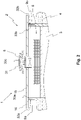
- figure 2 shows a further embodiment of the device 1 with a shut-off element 33. Only a section of the device 1 is shown here. Furthermore, compared to figure 1 only the essential new features are explained.
- An air inlet opening 31 of the at least one air inlet 8 and/or an air outlet opening 32 of the at least one air outlet 9 can be closed with a shut-off element 33 .
- the blocking element 33 can be used to prevent smaller animals from getting into the device 1 through the air inlet 8 or through the air inlet opening 31 and/or through the air outlet 9 or through the air outlet opening 32 .
- the corresponding blocking element 33 thus blocks the way for the animals.
- the shut-off element 33 is permeable to air, so that it impedes the air flow only very slightly.
- the at least one air inlet 8 has the air inlet opening 31 .
- the air inlet opening 31 of the at least one air inlet 8 is closed here with a shut-off element 33c.
- the two air outlets 9a, 9b shown here have the associated air outlet opening 32a, 32b.
- the two air outlets 9a, 9b can also be just one air outlet 9 if it extends completely around the device 1.
- the air outlets 9a, 9b or the air outlet openings 32a, 32b shown here are closed with an associated shut-off element 33a, 33b.
- These blocking elements 33a, 33b can be used to prevent animals, such as mice, martens or cats, from getting into the device 1 via the ground and through the air outlets 9a, 9b.
- shut-off elements 33a - 33c are arranged in the air outlet openings 32a, 32b and/or in the air inlet opening 31 .
- the at least one blocking element 33a - 33b can be designed as a grid.
- the at least one shut-off element 33a - 33b or the grid can comprise a plurality of rods, for example metal rods, which are parallel to one another or cross one another.
- the parallel bars can extend in the vertical, in the diagonal and/or in the horizontal direction. These can then block the at least one air inlet 8 or the air inlet opening 31 and/or the at least one air outlet 9 or the air outlet opening 32 in order to restrain animals.
- the shut-off element 33 can also be designed as a gate, as a perforated plate and/or as a mesh, in particular as a wire mesh.
- the projection 16 extends laterally beyond the air outlet openings 32a, 32b and thus preferably also laterally beyond the blocking elements 32a, 32b of the air outlets 9. This can prevent the shut-off elements 32a, 32b from getting wet from rain and that this moisture freezes due to the cold air exiting, impeding airflow.
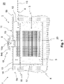
- figure 3 shows a schematic top view of a sectional view of a device 1 with the container 2 for receiving water 3 and for installation in the ground 4.
- the device 1 described here not all features are provided with a reference number and or are described if they are already in FIG preceding figure and/or if these are described in a subsequent figure or are at least similar or have a similar effect.
- the air heat exchanger 6 has an interior 20 and at least one side wall 21 delimiting the interior 20 .
- the side wall 21 is at least partially with the air 7 for exchanging thermal energy can flow through. When the air 7 flows through the side wall 21 , the air 7 gives off thermal energy to the air heat exchanger 6 or the air 7 absorbs thermal energy from the air heat exchanger 6 .
- the air inlet 8 is shown schematically by means of a dashed circle.
- air 7 thus flows from the surroundings 28 into the interior space 20 of the air heat exchanger 6 via the air inlet 8 .
- the air 7 flows from the interior 20 through the corresponding area of the side wall 21 to the outside.
- At least one section of the side wall 21 is formed by at least one plate heat exchanger 22 .
- Plate heat exchangers 22 can be manufactured in a simple manner, so that the manufacture of the air heat exchanger 6 is simplified.
- the air heat exchanger 6 comprises three plate heat exchangers 22a-22c, each of which forms at least a section of the side wall 21.
- the air heat exchanger 6 can also have more than three plate heat exchangers 22 . This further simplifies the manufacture of the air heat exchanger 6 .
- the at least one plate heat exchanger 22 is flat. Additionally or alternatively, the at least one plate heat exchanger 22 or another plate heat exchanger 22 of the air heat exchanger 6 can be curved.
- the air heat exchanger 6 can have the shape of a polygon, with at least one side of the polygon being formed at least in sections by the plate heat exchanger 22 .
- the polygon shown here is a triangle, with one plate heat exchanger 22a-22c forming a section of one side of the triangle.
- the one shown here Triangle is still an equilateral triangle.
- the interior space 20 with the plate heat exchangers 22a - 22c can be formed in a simple manner with the aid of the polygon.
- two plate heat exchangers 22a-22c meeting one another in the corners of the corresponding polygon are connected to one another by means of connecting elements 23a-23c. Additionally or alternatively, two plate heat exchangers 22a - 22c can also directly adjoin one another in the corners, so that there is no gap through which the air can flow past the plate heat exchangers.
- the side wall 21 is closed at least in the circumferential direction, so that the air can only flow through the side wall 21 through an area, in particular through the at least one plate heat exchanger 22, in which heat exchange can take place.
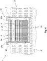
- FIG 4 shows a further device 1 in a schematic sectional view.
- the device 1 also includes a container 2 for holding water 3 and for installation in the ground 4.
- the container 2 has an assembly opening 30 into which a heat exchanger unit 24 of the device 1 can be introduced into the container 2 .
- the heat exchanger unit 24 comprises the water heat exchanger 5 , the air heat exchanger 6 arranged above the water heat exchanger 5 and a frame 25 accommodating these two.
- the heat exchanger unit 24 also includes laterally protruding mounting projections 26, by means of which the heat exchanger unit 24 can be hung on the container 2 in the region of the mounting opening 30, so that the heat exchanger unit 24 in the mounted state hovers above a container bottom 31 of the container 2.
- the heat exchanger unit 24 is spaced apart from the container 2 except for the area of the mounting extensions 26 .
- the container 2 can have a sealing film (not shown here) on its inside, which preferably extends over the container bottom 29 and/or at least partially over the container wall 17 .
- the container 2 can be sealed with the aid of the sealing film.
- the separation of the heat exchanger unit 24 from the container area of the sealing foil prevents damage to the sealing foil.
- the mounting projections 26 are formed on the frame 25 .
- Two mounting extensions 26a, 26b are shown here, it also being possible for the heat exchanger unit 24 to have a plurality of mounting extensions 26.
- the mounting extensions 26 may be spaced apart from one another along a circumferential direction.
- the mounting extensions 26 are hung on a container edge 27 of the container 2 .
- the heat exchanger unit 24 is in contact with the container 2 only in the area of the container edge 27 .
Landscapes
- Engineering & Computer Science (AREA)
- Mechanical Engineering (AREA)
- General Engineering & Computer Science (AREA)
- Physics & Mathematics (AREA)
- Thermal Sciences (AREA)
- Chemical & Material Sciences (AREA)
- Combustion & Propulsion (AREA)
- Life Sciences & Earth Sciences (AREA)
- Sustainable Development (AREA)
- Heat-Exchange Devices With Radiators And Conduit Assemblies (AREA)
- Other Air-Conditioning Systems (AREA)
- Cultivation Receptacles Or Flower-Pots, Or Pots For Seedlings (AREA)
Applications Claiming Priority (1)
| Application Number | Priority Date | Filing Date | Title |
|---|---|---|---|
| DE102021116292.0A DE102021116292A1 (de) | 2021-06-23 | 2021-06-23 | Vorrichtung mit einem Behälter zur Aufnahme von Wasser und zur Installation im Erdreich sowie mit Wärmetauschern |
Publications (2)
| Publication Number | Publication Date |
|---|---|
| EP4109025A2 true EP4109025A2 (fr) | 2022-12-28 |
| EP4109025A3 EP4109025A3 (fr) | 2023-03-01 |
Family
ID=82258432
Family Applications (1)
| Application Number | Title | Priority Date | Filing Date |
|---|---|---|---|
| EP22180587.2A Pending EP4109025A3 (fr) | 2021-06-23 | 2022-06-23 | Dispositif doté d'un récipient destiné à recevoir de l'eau et à être installé dans le sol, ainsi que pourvu d'échangeurs de chaleur |
Country Status (2)
| Country | Link |
|---|---|
| EP (1) | EP4109025A3 (fr) |
| DE (1) | DE102021116292A1 (fr) |
Families Citing this family (1)
| Publication number | Priority date | Publication date | Assignee | Title |
|---|---|---|---|---|
| DE102024114784A1 (de) * | 2024-05-27 | 2025-11-27 | Max Bögl Wind AG | Energietauschereinheit für eine Energiespeichervorrichtung |
Family Cites Families (5)
| Publication number | Priority date | Publication date | Assignee | Title |
|---|---|---|---|---|
| DE3108431A1 (de) | 1981-03-06 | 1982-10-21 | Wiedemann, Martin, 7095 Rainau | Energiesammelturm zur deckung des waermebedarfs der verbracher eines gebaeudes |
| DE102011117988B4 (de) | 2011-11-09 | 2013-07-04 | Heiner Andersen | Kühlanordnung zum Kühlen von in einem Raum in Schaltschränken angeordneten elektronischen Geräten |
| EP3842698A4 (fr) * | 2018-08-23 | 2021-11-03 | Mitsubishi Electric Corporation | Ensemble échangeur de chaleur et dispositif à cycle frigorifique |
| DE102019105265A1 (de) | 2019-03-01 | 2020-09-03 | Naturspeicher Gmbh | Vorrichtung mit einem Becken und einem Wärmetauscher zum Einbringen und/oder Entziehen von Wärmeenergie in bzw. aus einem Gewässer |
| DE102019118223B4 (de) | 2019-07-05 | 2026-03-12 | Envola GmbH | Vorrichtung zur Energieübertragung und zur Energiespeicherung in einem Flüssigkeitsreservoir |
-
2021
- 2021-06-23 DE DE102021116292.0A patent/DE102021116292A1/de active Pending
-
2022
- 2022-06-23 EP EP22180587.2A patent/EP4109025A3/fr active Pending
Also Published As
| Publication number | Publication date |
|---|---|
| EP4109025A3 (fr) | 2023-03-01 |
| DE102021116292A1 (de) | 2022-12-29 |
Similar Documents
| Publication | Publication Date | Title |
|---|---|---|
| EP3221655B1 (fr) | Procédé et dispositif d'introduction et d'extraction d'énergie calorifique dans un plan d'eau ou à partir d'un plan d'eau. | |
| EP2141360B1 (fr) | Eolienne pourvue d'un système de refroidissement du générateur | |
| DE112010005583T5 (de) | Datenzentrumskühlung | |
| DE2430475A1 (de) | Verfahren und kuehlturm zum abfuehren von abwaerme | |
| DE102004061391B4 (de) | Temperaturregelung in einer Windenergieanlage | |
| EP1419350A1 (fr) | Installation d'energie eolienne | |
| EP2635869A2 (fr) | Système et procédé d'introduction d'air pour tours de refroidissement | |
| DE202009014942U1 (de) | Klimaanlage | |
| EP4109025A2 (fr) | Dispositif doté d'un récipient destiné à recevoir de l'eau et à être installé dans le sol, ainsi que pourvu d'échangeurs de chaleur | |
| DE1501411A1 (de) | Kaminkuehler zum Kuehlen von Fluessigkeiten durch atmosphaerische Luft | |
| DE202011110056U1 (de) | Klimaschrank | |
| EP2218970B1 (fr) | Système d'équilibrage des températures | |
| DE10046702B4 (de) | Natürliches Lüftungssystem für Kuhställe | |
| DE102012206076A1 (de) | Stromschienensystem | |
| DE102018127869A1 (de) | Vorrichtung zur Gewinnung von elektrischer Energie sowie entsprechendes Verfahren | |
| DE2940830C2 (de) | Gebäude mit durchlüftbaren Kanälen in Wänden und Decken | |
| DE2808814A1 (de) | Verfahren und vorrichtung zum speichern und distribuieren von durch sonnenenergie aufgewaermter luft | |
| DE102015200347A1 (de) | Windkraftanlage | |
| DE102009053527A1 (de) | Klimaanlage | |
| DE202008014436U1 (de) | Anordnung und Verfahrensweise zur Nutzung der Wärmeentstehung an Photovoltaikanlagen innerhalb haustechnischer Anlagen | |
| DE102015217035A1 (de) | Windenergieanlage und Verfahren zum Steuern einer Kühlung einer Windenergieanlage | |
| DE2248895A1 (de) | Wasserkuehlturm fuer parallele luftwegnass-trockenkuehlung | |
| DE102006024341A1 (de) | Aufwindkraftwerk | |
| EP4048962A1 (fr) | Dispositif de production d'energie | |
| DE2431851A1 (de) | Trockener querstrom-kuehlturm |
Legal Events
| Date | Code | Title | Description |
|---|---|---|---|
| PUAI | Public reference made under article 153(3) epc to a published international application that has entered the european phase |
Free format text: ORIGINAL CODE: 0009012 |
|
| STAA | Information on the status of an ep patent application or granted ep patent |
Free format text: STATUS: THE APPLICATION HAS BEEN PUBLISHED |
|
| AK | Designated contracting states |
Kind code of ref document: A2 Designated state(s): AL AT BE BG CH CY CZ DE DK EE ES FI FR GB GR HR HU IE IS IT LI LT LU LV MC MK MT NL NO PL PT RO RS SE SI SK SM TR |
|
| PUAL | Search report despatched |
Free format text: ORIGINAL CODE: 0009013 |
|
| AK | Designated contracting states |
Kind code of ref document: A3 Designated state(s): AL AT BE BG CH CY CZ DE DK EE ES FI FR GB GR HR HU IE IS IT LI LT LU LV MC MK MT NL NO PL PT RO RS SE SI SK SM TR |
|
| RIC1 | Information provided on ipc code assigned before grant |
Ipc: F24V 50/00 20180101ALI20230124BHEP Ipc: F28D 20/00 20060101AFI20230124BHEP |
|
| STAA | Information on the status of an ep patent application or granted ep patent |
Free format text: STATUS: REQUEST FOR EXAMINATION WAS MADE |
|
| 17P | Request for examination filed |
Effective date: 20230830 |
|
| RBV | Designated contracting states (corrected) |
Designated state(s): AL AT BE BG CH CY CZ DE DK EE ES FI FR GB GR HR HU IE IS IT LI LT LU LV MC MK MT NL NO PL PT RO RS SE SI SK SM TR |
|
| STAA | Information on the status of an ep patent application or granted ep patent |
Free format text: STATUS: EXAMINATION IS IN PROGRESS |
|
| 17Q | First examination report despatched |
Effective date: 20241129 |