EP4109063B1 - Lebensdauerschätzung von elektrolytkondensatoren - Google Patents
Lebensdauerschätzung von elektrolytkondensatoren Download PDFInfo
- Publication number
- EP4109063B1 EP4109063B1 EP21181255.7A EP21181255A EP4109063B1 EP 4109063 B1 EP4109063 B1 EP 4109063B1 EP 21181255 A EP21181255 A EP 21181255A EP 4109063 B1 EP4109063 B1 EP 4109063B1
- Authority
- EP
- European Patent Office
- Prior art keywords
- lifetime
- controller
- capacitor
- consumption
- lifetime consumption
- Prior art date
- Legal status (The legal status is an assumption and is not a legal conclusion. Google has not performed a legal analysis and makes no representation as to the accuracy of the status listed.)
- Active
Links
Images


Classifications
-
- G—PHYSICS
- G01—MEASURING; TESTING
- G01R—MEASURING ELECTRIC VARIABLES; MEASURING MAGNETIC VARIABLES
- G01R31/00—Arrangements for testing electric properties; Arrangements for locating electric faults; Arrangements for electrical testing characterised by what is being tested not provided for elsewhere
-
- G—PHYSICS
- G01—MEASURING; TESTING
- G01K—MEASURING TEMPERATURE; MEASURING QUANTITY OF HEAT; THERMALLY-SENSITIVE ELEMENTS NOT OTHERWISE PROVIDED FOR
- G01K1/00—Details of thermometers not specially adapted for particular types of thermometer
- G01K1/14—Supports; Fastening devices; Arrangements for mounting thermometers in particular locations
- G01K1/143—Supports; Fastening devices; Arrangements for mounting thermometers in particular locations for measuring surface temperatures
-
- G—PHYSICS
- G01—MEASURING; TESTING
- G01R—MEASURING ELECTRIC VARIABLES; MEASURING MAGNETIC VARIABLES
- G01R31/00—Arrangements for testing electric properties; Arrangements for locating electric faults; Arrangements for electrical testing characterised by what is being tested not provided for elsewhere
- G01R31/36—Arrangements for testing, measuring or monitoring the electrical condition of accumulators or electric batteries, e.g. capacity or state of charge [SoC]
- G01R31/392—Determining battery ageing or deterioration, e.g. state of health
-
- G—PHYSICS
- G01—MEASURING; TESTING
- G01R—MEASURING ELECTRIC VARIABLES; MEASURING MAGNETIC VARIABLES
- G01R31/00—Arrangements for testing electric properties; Arrangements for locating electric faults; Arrangements for electrical testing characterised by what is being tested not provided for elsewhere
- G01R31/50—Testing of electric apparatus, lines, cables or components for short-circuits, continuity, leakage current or incorrect line connections
- G01R31/64—Testing of capacitors
Definitions
- the invention relates to a device and a method to estimate the lifetime of electrolytic capacitors as well as an apparatus which uses electrolytic capacitors and comprises a device to estimate their lifetime according to the invention.
- Electrolytic capacitors are known to age and this aging depends on the temperature of the electrolyte. Producers of electrolytic capacitors often provide their customers with formulas or nomograms to estimate the lifetime consumption at a given temperature. Similar to the Arrhenius equation describing chemical reaction rates as a function of a temperature, the lifetime consumption is estimated by an exponential function.
- the lifetime consumption depends exponentially on the core temperature. Therefore uncertainties in the estimate of the core temperature cause great uncertainties in the estimated lifetime. As the lifetime consumption is integrated over time to yield the total lifetime consumption, the uncertainty can reach values which make the result essentially useless.
- Arranging a sensor inside the capacitor is technically challenging and bears the risk that, due to an additional opening in the sealing, the electrolyte evaporates faster than without the sensor which would limit the lifetime of the capacitor.
- the use of thermal models of the inside of an apparatus is difficult, as there are in general different electrical parts which produce different amount of heat when used in different situations. In addition, it is in most cases unknown how a given apparatus will be arranged in the room where it is finally used and therefore, the cooling efficiency of different parts of the housing of the apparatus is in general unknown to the producer.
- the device to estimate the lifetime of one or more electrolytic capacitors comprises a temperature sensor and a controller which is suitable to estimate the lifetime consumption of an electrolytic capacitor based on the measurement data of the temperature sensor.
- the shape of the capacitors is approximately a round cylinder with a radius R and a height h.
- the capacitors are arranged with their longitudinal axis being parallel and being arranged in a distance 2D from each other.
- the temperature sensor is in the direction perpendicular to the connecting line of the two longitudinal axis and perpendicular to the two longitudinal axis smaller than the difference between the square root of 8 and the distance 2D between the two capacitors.
- the temperature sensor is smaller than the difference between the height h and the distance 2D minus twice the radius R.
- the temperature sensor Arranging the temperature sensor on the case of an electrolytic capacitor and thermally insulating it by covering it with a layer of thermally insulating material allows the device to comprise only one electrolytic capacitor.
- the temperature sensor is preferably arranged in a region which is difficult to cool even without the insulating material such as between the electrolytic capacitor and a mounting board or parts of the casing of the apparatus.
- the “total lifetime” is the time the capacitor at hand will be working when being subject to the conditions it was and it will be subject, too.
- a clock started when the capacitor is built and stopped in the moment when the capacitor fails, would show the “total lifetime”.
- the total lifetime is expressed in units of time.
- the “base lifetime” L 0 is the lifetime of the capacitor at hand at its maximum rated category temperature T 0 and when subject to its reference ripple current I S .
- the base lifetime is expressed in units of time, for example in hours.
- the base lifetime is a parameter in the models to estimate the lifetime. Therefore, the unit of the base lifetime is in many cases, and if the unit is not changed on purpose, the unit of the lifetime.
- the “maximum age” is the duration the capacitor at hand would be working if it is not used but only stored at room temperature without specific protection but also without the exposure to specific extreme conditions.
- the maximum age is expressed in units of time, typically years. A typical maximum age is about 15 years for common electrolytic capacitors.
- the device comprises a meter which can measure an output or input data.
- the output or input data comprises a voltage, a power or a current which is either influenced by the one or more electrolytic capacitors or which influences the one or more electrolytic capacitors.
- the controller of this embodiment is suitable to include the measured output or input data in its estimation of the lifetime consumption of the electrolytic capacitor.
- Especially aluminum electrolytic capacitors create internal heat when ripple currents flow through them. Measuring the output or input data allows, together with known properties of the apparatus in which the electrolytic capacitors are used and therefore the implicit information on how the measured data correlates with the ripple current through the capacitor, to estimate this internally produced heat and thereby the use of a more precise thermal model of the electrolytic capacitor.
- a voltage, power or current influences the capacitor or is influenced by the capacitor if a change in this voltage, power or current changes the ripple current through the capacitor.
- the measured property may be the frequency, the mode the waveform and/or the number of phases.
- the input conditions are known, as an apparatus is often built for specific input conditions such as a one or three phase voltage with a given root mean square voltage and frequency and a known line voltage waveform or a known mode.
- the number phases and the mode of the output is often given by the circuitry and the specification of the apparatus. Therefore, in such embodiments, a measurement specifying the output voltage, power or current is sufficient to determine the situation of the apparatus and to derive therefrom the effective ripple current.
- An apparatus according to the invention comprises at least one electrolytic capacitor and a device according to the invention.
- the controller comprises or is able to access a memory in which the association between the detected input and output properties and the effective ripple current is given.
- This association can be done for example in the form of a set of look-up-tables or in the form of one or more formulas.
- there a separate look-up-tables or formulas for, if applicable, the different possible combinations of phases on in- and output, for AC and DC output while the tables and/or formulas connect the RMS voltages, currents or power detected by the first and second detector to the effective ripple current for the apparatus at hand.
- the association is derived by the manufacturer of the apparatus and read into the controller when the device is installed in a given apparatus.
- the controller estimates the effective ripple current I a considering the number of phases and/or the mode and/or the waveform on the input of the apparatus and an output mode of the apparatus as well as a measured or given power or current or input voltage value.
- the ripple current is sampled with a frequency of at least twice the highest frequency of interest to the situation at hand and the measurements are analyzed to determine the ripple currents at different frequencies.
- This analysis is preferably a Fast Fourier Transformation (FFT).
- FFT Fast Fourier Transformation
- the ESR values or frequency multipliers for the capacitor at hand at the different frequencies are obtainable by the controller for example by being saved in the form of a table or a function in a memory which is part of or accessible by the controller.
- the frequency multiplier of a given frequency is preferably the square root of the ratio of the ESR value of the frequency f 0 of the reference ripple current I s and the ESR value of this given frequency.
- the lifetime L x is estimated with the formula given above in the time unit which was used for the base lifetime L 0 .
- the case temperature T c and/or the effective ripple current I a vary with time and therefore, only a part of the estimated lifetime L x is actually used during a time segment ⁇ t during which the case temperature T c and/or the effective ripple current I a are essentially constant.
- the thermal model on which these formulas are based represents the capacitor by a heat source in its core, which is the dissipated ripple current and by a second heat source which is the ambient air. In between, the heat is conducted from the core to the case and from the case to the ambient. The efficiency of this heat conduction is described by the thermal resistivities R thjc , R thca .
- T a I a T c I a ⁇ ⁇ T m I s R thca R thjc + R thca I a I s 2
- L x I a T a L 0 2 T 0 ⁇ T a 10 K 2 ⁇ T m ⁇ ⁇ T I a 5 K
- T 0 is a reference temperature
- I s is the reference ripple current
- ⁇ T m is the temperature difference between the core and the ambient when the reference ripple current I s is flowing through the capacitor.
- K is the unit Kelvin.
- L 0 is the lifetime if the ambient temperature T a equals the reference temperature T 0 and the effective ripple current I a equals the reference ripple current I s .
- the controller estimates a lifetime consumption (LC) of the at least one electrolytic capacitor during a time segment ( ⁇ t) to be proportional to the quotient of the time segment ( ⁇ t) over the lifetime.
- the lifetime is determined for the case temperature (T c ) and the effective ripple current (I a ) which are measured or assumed to occur during this time segment.
- the lifetime consumption is preferably determined in order to be able to integrate it over time and to estimate thereby the residual lifetime.
- the lifetime consumption LC is preferably expressed in a percentage or a fraction of the lifetime. As the lifetime may differ from time segment to time segment, the lifetime consumption may differ between subsequent time segments, too.
- the lifetime consumption LC at a specific point in time is inverse proportional to the lifetime L x : LC c t ⁇ 1 L x .
- the controller determines an uncertainty in the lifetime consumption taking into account the uncertainties in the case temperature, the effective ripple current and preferably the time segment.
- the lifetime consumption is estimated in and for regular time segments.
- the time segments are measured, too and have consequently a small uncertainty which can be considered in the total uncertainty of the lifetime consumption LC d ( ⁇ t) in the discrete case.
- the propagation of the uncertainty is preferably determined with the help of a truncated Taylor Series around the measured values which is once evaluated to give the most negative deviation and once to give the most positive deviation due to the positive and negative uncertainties of the parameters discussed above.
- the controller of the apparatus determines the lifetime consumption and preferably its uncertainty in regular time segments. Every time segment is represented by a mean temperature and a mean effective current.
- the mean temperature and the mean effective current or the mean input voltage are preferably averages over all suitable measurements obtained during the time interval.
- the total lifetime consumption is, in this embodiment, the sum over all previous lifetime consumptions.
- the total lifetime consumption is preferably determined and stored.
- the user can specify a usage cycle.
- the usage cycle is expected to be repeated in the future.
- This embodiment allows the user to obtain a residual lifetime estimation in the units of a usage cycle. This number is often more comprehensive than a number of hours as the user will most likely want to schedule maintenance and repairs to take place between usage cycles. Further, counting usage cycles yields, in most cases, a result with a smaller uncertainty compared measuring the current time and determining the duration of a usage cycle.
- measurements are well represented by the recorded or defined usage cycle, if the change of the case temperature with time is similar to the one of the recorded or defined usage cycle while greater differences are accepted in the absolute values of the measurements.
- the user may set a first threshold regarding the change of the case temperature measurements and/or the ripple current estimate and a second threshold regarding the absolute values of the case temperature, the effective ripple current and/or the lifetime.
- the controller assumes that an observed usage cycle is well represented by the recorded or defines usage cycle if the difference in the change is below the first threshold and if the difference in the absolute value is below the second threshold.
- the user can detect and analyze long term changes in the apparatus. For example, a long term change in the case temperature may be caused by the seasons but also by a degrading of surrounding components in the apparatus which provide more heat that previously. Further, the user may use the data to optimize the use of the apparatus to increase its lifetime.
- the controller comprises, besides the interface a button which allows to specify the usage cycle and a display or a light indicator to indicate that amount of the residual lifetime.
- the usage cycle may be defined by pushing the button once at the beginning and twice at the end of the usage cycle and the light indicator may glow in green as long as the residual lifetime is more than 25% of the shorter one of the preliminary predicted lifetime and the maximum age and turn to orange once this fraction reduces to 10% and to red once there is no residual lifetime anymore.
- a flashing light indicator may signal that the currently used usage cycle appears to be a poor representation of the current usage of the apparatus.
- the temperature sensor 32 is therefore mounted on the case 11 of the electrolytic capacitor 1, respectively directly on the sleeve 12.
- the sleeve 12 is sufficiently thin to be treated as part of the case 11 in the temperature model.
- the temperature sensor 32 is thermally insulated from the ambient 15 by a layer 320 of thermally insulating material. Thereby, the temperature of the temperature sensor 32, and as a result the measured value, is dominated by the temperature of the case 11.
- the temperature sensor 32 is connected to a controller 31 which uses the case temperature measurements to estimate the lifetime of the capacitor.
- the temperature sensor 32 transmits its data via a cable. In other embodiments, a wireless transmission can be used.
- the temperature sensor 32 is mounted between two the electrolytic capacitors 1a, 1b which are connected in parallel.
- the two electrolytic capacitors 1a and 1b are of the same type and the same size and, as being connected in parallel, subject to the same internal heating and, as being located adjacent to each other, subject to the same ambient conditions.
- Figure 2b shows the situation from the side
- Figure 2c shows the situation from the top.
- the temperature sensor 32 is, seen from all sides, arranged between the two capacitors. As both capacitors 1a and 1b produce the same amount of heat, the temperature between them will be equal to the common case temperature.
- FIG. 3 shows a thermal model 2 on which the lifetime estimate according to the invention is based.
- the model describes three sections: There is the core 10 of the capacitors, the case 11 and the ambient 15.
- the core 10 and the case 11 are modelled as heat capacitances.
- the ambient 15 is modelled as voltage source-equivalent providing a constant, ambient temperature.
- the core 10 comprises in addition and parallel to the heat capacitance, a power source-equivalent representing the heat source created by the power loss in the core 10 during use.
- the interfaces between the three sections are modelled by thermal resistors.
- the first one of these interfaces is between the core 10 and the case 11 and it has the thermal resistance between core and case 201 R thjc .
- the second one of these interfaces is between the case 11 and the ambient 15 and it has the thermal resistance between case and ambient 215 R thca .
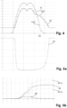
- Figure 4 shows an example of development of the case temperature 42 and the effective ripple current 41 over time during a usage cycle.
- Case temperature 42 and effective ripple current 41 are given in arbitrary units and plotted on the common y-axis. The time evolves along the common x-axis.
- the case temperature equals the ambient temperature.
- a ripple current appears and starts to produce heat which increases the temperature of the core. The heat is conducted to the case and the temperature increase is detected. The ripple current varies during use and finally decreases to zero when the apparatus is turned off. In the absence of heating, the conductor cools until the case temperature equal the ambient temperature.
- the lifetime estimate and/or the consumed lifetime are derived using a mean temperature 420 and/or a mean effective ripple current 410 to represent the situation in a given time segment 55.
- the time segments 55 are chosen such that the change in temperature 42 and effective ripple current 41 is small.
- large time segments 55 were chosen, mainly to illustrate the principle. However, even these large time segments 55 give a rough representation of the development of the case temperature and the effective ripple current and can be used, for example, to ensure that a specified usage cycle is in progress.
- Figure 5a shows the estimated lifetime 43 based on the case temperature 42 and the effective ripple current 41 shown in Figure 4.
- Figure 5b shows the lifetime consumption 44 and the total lifetime consumption 45. While the estimated lifetime 43 shown in Figure 5a is given in time units, the lifetime consumption 44 and the total lifetime consumption 45 are given as a fraction or as a percentage of the total lifetime of the capacitor. In the case shown, the lifetime consumption 44 is expressed as fraction of the total lifetime of the capacitor per unit time and the total lifetime consumption is expressed as fraction of the total lifetime of the capacitor. Therefore, if the total lifetime consumption 45 reaches the value 1 the capacitor has reached the end of its preliminary predicted lifetime and will likely start to show degradation effects.
- the lifetime consumption 44 is proportional to one time unit over the estimated lifetime 43 and the total lifetime consumption 45 is the integral of the lifetime consumption 44 over time. Consequently, the total lifetime consumption 45 at the end of the first usage cycle can be used as an estimate for the usage cycle lifetime consumption. If a usage cycle is defined later in the service life of an electrolytic capacitor, the usage cycle lifetime consumption is the difference between the total lifetime consumption 45 at the end of the usage cycle and the total lifetime consumption 45 at its beginning.
- Figures 5a and 5b show the first usage cycle of the electrolytic capacitor:
- the total lifetime consumption 45 is zero at the beginning of the illustrated time interval. If the electrolytic capacitor at hand would have experienced previous usage cycles, the total lifetime consumption 45 would have a value different from zero at the beginning of the illustrated time interval. However, the curves of the lifetime estimate 43 and the lifetime consumption 44 would be the same as the ones shown.
- the continuous lines show the lifetime estimate 43, the lifetime consumption 44 and the total lifetime consumption 45 evaluated based on the continuous measurements of case temperature 42 and effective ripple current 41.
- the horizontal lines illustrate the values obtained by using the mean temperature 420 and the mean effective ripple current 410 as assumed constant values for the time segment 55 in question. While the choice of the large time segments 55 causes some deviation from the exact value of the total lifetime consumption 45 in times where the lifetime consumption 44 changes, the difference is at the end of the usage cycle sufficiently small to be usable.
- Figure 5b shows in addition the total lifetime consumptions for a case temperature which is 5% lower (451b) or 5% higher (451a) than the one shown in Figure 4 .
- a case temperature which is 5% lower (451b) or 5% higher (451a) than the one shown in Figure 4 .
- Figure 4 shows a case with 20°C ambient temperature, a 5% error is +/- 1°C while the apparatus is turned off.
- the uncertainty in the total lifetime consumption is even after a single usage cycle about half of the value itself. This illustrates that a precise temperature measurement is of key importance for a useful lifetime consumption estimation and even more for a useful prediction of the residual lifetime.
- the upper diagram of Figure 6 shows the case temperature measurements 42 and the effective ripple current values 41 over time.
- the capacitor is used in an apparatus with a first usage cycle 51a. Later, the apparatus is used differently and has therefore a second usage cycle 51b.
- the length of the first and the second usage cycle 51a and 51b is similar but the amplitude of case temperature and effective ripple current is differently.
- the amplitudes may be similar but the durations of the usage cycles differs.
- the usage cycles differ in the amplitude and/or the shape of the temperature and/or the effective ripple current curve and in addition in their durations. There is also a time during which the case temperature development and the effective ripple current development differ from both, the first and the second usage cycle.
- FIG. 7 shows a power supply which is an apparatus typically comprising a bulk capacitor 72 which can be constructed using electrolytic capacitors 1.
- the bulk capacitor 72 is realized by a set of two electrolytic capacitors 1 of the same type which are connected in parallel.
- the lifetime of this bulk capacitor 72 is estimated using a device according to the invention comprising a temperature sensor 32 which is arranged between the two electrolytic capacitors such that it can measure their common case temperature 42 with a high accuracy.
- the device comprises further an ammeter 34 which is used to determine the effective ripple current.
- the temperature sensor 32 and the ammeter 34 are connected to a controller 31 which is in this case equipped with an output device in the form of a display and an input device in the form of a button.
- the data to be transmitted to the memory device or to a display or which are displayed on the controller itself can comprise the residual lifetime, the current lifetime estimate, the current lifetime consumption, the current total lifetime consumption, the timeline of the past lifetime estimates, the timeline of the past lifetime consumption, the timeline of the past values of the total lifetime consumption, the timeline of the measures case temperatures and/or the current case temperature, the timeline of the effective ripple current values, the current effective ripple current and the timeline as well as the current values of the variables used to estimate the effective ripple current.
- the controller may present the data in statistical form and provide the user for example with histograms showing the number of time segments with a given lifetime consumption or the number of time segments which were considered to not belong to the usage cycle set at the time of their occurrence.
Landscapes
- Physics & Mathematics (AREA)
- General Physics & Mathematics (AREA)
- Engineering & Computer Science (AREA)
- Power Engineering (AREA)
- Testing Electric Properties And Detecting Electric Faults (AREA)
Claims (13)
- Vorrichtung mit mindestens einem Elektrolytkondensator (1, 1a, 1b) und einer Einrichtung (3) zum Abschätzen des Lebensdauerverbrauchs (44) des mindestens einen Elektrolytkondensators (1, 1a, 1b), dadurch gekennzeichnet, dass die Einrichtung umfassta) einen Temperatursensor (32), der durch seine Anordnung von der Umgebung (15) thermisch isoliert isti) entweder zwischen zwei gleichen Elektrolytkondensatoren (1a, 1b), die parallel miteinander verbunden sind, oderii) auf einem Gehäuse (11) des mindestens einen Elektrolytkondensators (1, 1a, 1b) und bedeckt mit einer Schicht aus wärmeisolierendem Material (320), undb) einen Controller (31), der geeignet ist, den Lebensdauerverbrauch (44) auf der Grundlage der Messdaten des Temperatursensors (32) zu schätzen,wobei die Vorrichtung es dem Benutzer ermöglicht, einen Nutzungszyklus (51) vorzugeben, von dem erwartet wird, dass er sich in der Zukunft wiederholt, und wobei der Controller (31) den Lebensdauerverbrauch (44) und vorzugsweise seine Unsicherheit entweder in Zeitsegmenten (55) oder kontinuierlich während des Nutzungszyklus (51) bestimmt, und wobei der Controller (31) den Nutzungszyklus Lebensdauerverbrauch durch Integration der kontinuierlich bestimmten Lebensdauerverbräuche (44) über den Nutzungszyklus (51) oder durch Addition der Lebensdauerverbräuche (44) aller Zeitsegmente (55) des Nutzungszyklus (51) bestimmt und vorzugsweise die Unsicherheit des Nutzungszyklus Lebensdauerverbrauchs bestimmt,wobei der Nutzungszyklus Lebensdauerverbrauch von dem Controller (31) verwendet wird, um eine vorläufige vorhergesagte Lebensdauer (54a, b) durch lineare Extrapolation des gesamten Lebensdauerverbrauchs (LCtotal(t), 45) zu bestimmen,wobei die vorläufige vorhergesagte Lebensdauer (Lpp, 54a,b) die Dauer zwischen dem Beginn der Lebens des Kondensators und dem Zeitpunkt ist, an dem die Extrapolation des gesamten Lebensdauerverbrauchs (LCtotal(t) , 45) einen Wert erreicht, der das Ende der Lebensdauer anzeigt,wobei der Controller (31) zusätzlich vorzugsweise eine Clock umfasst, die ein Alter des einen oder der mehreren Elektrolytkondensatoren (1, 1a, 1b) zählt,wobei die Restlebensdauer (52) von dem Controller (31) als die kleinere der beiden folgenden Zahlen geschätzt wird:i) die vorläufige vorhergesagte Lebensdauer (54a, b) minus das aktuelle Alter des einen oder der mehreren Elektrolytkondensatoren (1, 1a, 1b)ii) das maximale Alter (53) des einen oder der mehreren Elektrolytkondensatoren (1, 1a, 1b) minus das aktuelle Alter des einen oder der mehreren Elektrolytkondensatoren (1, 1a, 1b)und wobei die Restlebensdauer (52) vorzugsweise zusammen mit ihrer Unsicherheit zurückgegeben wird.
- Vorrichtung (3) nach Anspruch 1, umfassenda) ein Messgerät, das Ausgangs- oder Eingangsdaten messen kann, die eine Eigenschaft einer Spannung, einer Leistung und/oder eines Stroms sind, die von dem einen oder den mehreren Elektrolytkondensatoren (1, 1a, 1b) beeinflusst wird oder die diese beeinflusst, undb) wobei der Controller (31) geeignet ist, die gemessenen Ausgangs- oder Eingangsdaten in seine Schätzung des Lebensdauerverbrauchs (44) des einen oder der mehreren Elektrolytkondensatoren (1, 1a, 1b) einzubeziehen.
- Vorrichtung nach Anspruch 2, umfassend
entwedera) einen ersten Detektor, der geeignet ist, die Eigenschaften einer Eingangsspannung, eines Eingangsstroms oder einer Eingangsleistung für die Vorrichtung zu erfassen,b) einen zweiten Detektor, der geeignet ist, die Eigenschaften einer Ausgangsspannung, eines Ausgangsstroms oder einer Ausgangsleistung der Vorrichtung zu erfassen
und/oderc) einen Strommesser, der geeignet ist, einen Strom durch den einen oder die mehreren Elektrolytkondensatoren (1, 1a, 1b) zu messen,wobei der Controller geeignet ist, die Messungen des ersten und des zweiten Detektors oder des Strommessers in seine Schätzung des Lebensdauerverbrauchs (44) einzubeziehen. - Vorrichtung nach einem der Ansprüche 1 bis 3, wobei der Controller den effektiven Ripplestrom Ia, und vorzugsweise seine Unsicherheit schätzt, indem er die Anzahl der Phasen und/oder die Mode und/oder die Wellenform am Eingang der Vorrichtung, eine Ausgangsmode der Vorrichtung und einen gegebenen oder gemessenen Ausgangsleistungswert oder einen gegebenen oder gemessenen Stromwert oder einen gegebenen oder gemessenen Eingangsspannungswert berücksichtigt.
- Vorrichtung nach Anspruch 4, bei der der Controller den effektiven Ripplestrom la unter Verwendung einer einer Menge von Lookup-Tabellen schätzt,a) wobei die anzuwendende Lookup-Tabelle in Abhängigkeit von der Anzahl der Phasen und/oder der Mode und/oder der Wellenform des Eingangs der Vorrichtung und von einer Ausgangsmode des Geräts gewählt wird undb) wobei die Lookup-Tabelle den effektiven Ripplestrom la und vorzugsweise eine Unsicherheit des effektiven Stroms Ia zurückgibt beii) einem gegebenen oder gemessenen Wert der Ausgangsleistung oderii) bei einem gegebenen oder gemessenen Stromwert oderiii) bei einem gegebenen oder gemessenen Eingangsspannungswert.
- Vorrichtung nach einem der Ansprüche 1 bis 5, die eine Stromversorgung (7) ist, umfassenda) einen Gleichrichter (71),b) einen Bulk-Kondensator (72),c) einem Transformator (74), undd) vorzugsweise einen Ausgangskondensator (75)e) wobei der Bulk-Kondensator (72) den mindestens einen Elektrolytkondensator (1, 1a, 1b) umfasst, undf) wobei der Lebensdauerverbrauch (44) des Bulk-Kondensators (72) mit einer Einrichtung (3) nach einem der Ansprüche 1 bis 2 geschätzt wird.
- Vorrichtung nach einem der Ansprüche 1 bis 6, wobei der Controller (31) eine Lebensdauer (43) des mindestens einen Elektrolytkondensators (1, 1a, 1b) durch Berechnen des Produkts aus einer ersten kondensatortypabhängigen Konstante (C1) und einer ersten und einer zweiten Exponentialfunktion schätzta) wobei der Exponent der ersten Exponentialfunktion die von dem Temperatursensor (32) gemessene Gehäusetemperatur (Tc) ist, während die Basis vorzugsweise eine Konstante ist, die unabhängig von dem Kondensatortyp (Q) ist, undb) der Exponent der zweiten Exponentialfunktion ist das Quadrat eines effektiven Ripplestroms (

- Vorrichtung nach einem der Ansprüche 1-7, wobei der Controller (31) einen Lebensdauerverbrauch (44) des mindestens einen Elektrolytkondensators (1, 1a, 1b) während eines Zeitsegments (55, □t) proportional zum Quotienten aus dem Zeitsegment (55, □t) über die Lebensdauer (43), die für die Gehäusetemperatur (Tc) und den effektiven Ripplestrom (Ia), die während des Zeitsegments (55) gemessen oder angenommen werden, bestimmt ist, schätzt, und wobei der Lebensdauerverbrauch (44) vorzugsweise gleich dem Quotienten aus dem Zeitsegment (55, □t) über der Lebensdauer (43) während dieses Zeitsegments (55) ist.
- Vorrichtung nach einem der Ansprüche 1-8, wobei der Controller (31) eine Unsicherheit im Lebensdauerverbrauch (44) unter Berücksichtigung der Unsicherheiten in der Gehäusetemperatur (Tc), dem effektiven Ripplestrom (Ia) und vorzugsweise dem Zeitsegment (ΔΔt) bestimmt.
- Vorrichtung nach einem der Ansprüche 1-9, wobei der Controller (31)a) den Lebensdauerverbrauch (44) und vorzugsweise seine Unsicherheit in regelmäßigen Zeitsegmenten bestimmt,b) wobei jedes Zeitsegment (55) durch eine mittlere Temperatur und einen mittleren effektiven Ripplestrom repräsentiert wird, die vorzugsweise Mittelwerte über alle geeigneten, während des Zeitsegments (55) erhaltenen Messungen sind, undc) wobei der gesamte Lebensdauerverbrauch (45) die Summe aller zuvor ermittelten Lebensdauerverbräuche (44) ist, und wobei der gesamte Lebensdauerverbrauch (45) vorzugsweise bestimmt und gespeichert wird.
- Vorrichtung nach einem der vorangehenden Ansprüche, wobeia) der Controller (31) die Gehäusetemperaturmessungen oder die Lebensdauerverbräuche (44) und vorzugsweise den geschätzten effektiven Ripplestrom des Nutzungszyklus (51) während seiner Vorgabe aufzeichnet und diese aufgezeichneten Datensequenzen mit den Datensequenzen vergleicht, die während Zeiten entstehen, die als Wiederholungen des Nutzungszyklus (51) angenommen werden, undb) der Controller (31) ein Signal an den Benutzer ausgibt, wenn er feststellt, dass eine Abweichung zwischen den aufgezeichneten und den gemessenen Daten größer ist als ein Schwellenwert, wodurch er vor einem Qualitätsverlust bei der Schätzung der Restlebensdauer (52) warnt und den Benutzer vorzugsweise auffordert, einen neuen Nutzungszyklus (51) anzugeben.
- Vorrichtung nach einem der vorhergehenden Ansprüche, bei der die Extrapolation der vorläufig vorhergesagten Lebensdauer (54a,b) und/oder die sich daraus ergebende Restlebensdauer (52) regelmäßig aktualisiert wird, so dass die neuesten verfügbaren Daten über Alter und Gesamtlebensdauerverbrauch (45) bei der Extrapolation berücksichtigt werden.
- Vorrichtung nach einem der Ansprüche 10 bis 12, wobei der Controller (31) eine Schnittstelle aufweist und die Temperatur, vorzugsweise den effektiven Ripplestrom und den Lebensdauerverbrauch (44) für jedes Zeitsegment (55) speichert, so dass sie oder eine daraus abgeleitete Statistik über die Schnittstelle exportiert werden können.
Priority Applications (4)
| Application Number | Priority Date | Filing Date | Title |
|---|---|---|---|
| EP21181255.7A EP4109063B1 (de) | 2021-06-23 | 2021-06-23 | Lebensdauerschätzung von elektrolytkondensatoren |
| US17/847,213 US12038485B2 (en) | 2021-06-23 | 2022-06-23 | Lifetime estimation of electrolytic capacitors |
| CN202210719344.2A CN115508634B (zh) | 2021-06-23 | 2022-06-23 | 电解电容器的寿命估计 |
| US18/731,387 US20240319287A1 (en) | 2021-06-23 | 2024-06-03 | Lifetime estimation of electrolytic capacitors |
Applications Claiming Priority (1)
| Application Number | Priority Date | Filing Date | Title |
|---|---|---|---|
| EP21181255.7A EP4109063B1 (de) | 2021-06-23 | 2021-06-23 | Lebensdauerschätzung von elektrolytkondensatoren |
Publications (3)
| Publication Number | Publication Date |
|---|---|
| EP4109063A1 EP4109063A1 (de) | 2022-12-28 |
| EP4109063B1 true EP4109063B1 (de) | 2025-04-09 |
| EP4109063C0 EP4109063C0 (de) | 2025-04-09 |
Family
ID=76584434
Family Applications (1)
| Application Number | Title | Priority Date | Filing Date |
|---|---|---|---|
| EP21181255.7A Active EP4109063B1 (de) | 2021-06-23 | 2021-06-23 | Lebensdauerschätzung von elektrolytkondensatoren |
Country Status (2)
| Country | Link |
|---|---|
| US (2) | US12038485B2 (de) |
| EP (1) | EP4109063B1 (de) |
Families Citing this family (3)
| Publication number | Priority date | Publication date | Assignee | Title |
|---|---|---|---|---|
| EP4109063B1 (de) * | 2021-06-23 | 2025-04-09 | Delta Electronics (Thailand) Public Co., Ltd. | Lebensdauerschätzung von elektrolytkondensatoren |
| CN118362818B (zh) * | 2024-06-20 | 2024-08-20 | 山东德佑电气股份有限公司 | 一种基于热能传递的电容器容值衰减评估方法 |
| WO2026068003A1 (en) * | 2024-09-26 | 2026-04-02 | Eaton Intelligent Power Limited | System and method for monitoring remaining useful life of a capacitor in an uninterruptable power supply |
Family Cites Families (14)
| Publication number | Priority date | Publication date | Assignee | Title |
|---|---|---|---|---|
| JPH0627175B2 (ja) | 1985-05-28 | 1994-04-13 | 日本ペイント株式会社 | 速硬化性樹脂組成物 |
| JPH0627175A (ja) | 1992-07-07 | 1994-02-04 | Toyota Autom Loom Works Ltd | コンデンサの寿命計算装置 |
| US6680585B2 (en) * | 2001-12-17 | 2004-01-20 | Osram Sylvania Inc. | Method and apparatus for modulating HID ballast operating frequency using DC bus ripple voltage |
| JP3850311B2 (ja) * | 2002-02-21 | 2006-11-29 | オムロン株式会社 | 残存寿命予測報知方法および電子機器 |
| US20050287402A1 (en) * | 2004-06-23 | 2005-12-29 | Maly Douglas K | AC impedance monitoring of fuel cell stack |
| DE102004035723A1 (de) | 2004-07-23 | 2006-02-16 | Siemens Ag | Verfahren und Vorrichtung zur Ermittlung einer Restlebensdauer eines Elektrolytkondensators eines Frequenzumrichters |
| CN102176377A (zh) * | 2011-01-31 | 2011-09-07 | 李纯廉 | 一种控制电解电容温度的方法及使用该方法可控温的电解电容 |
| WO2013183118A1 (ja) * | 2012-06-05 | 2013-12-12 | 三菱電機株式会社 | 電動機制御装置 |
| DE102012105198B4 (de) | 2012-06-15 | 2020-09-10 | Ebm-Papst Mulfingen Gmbh & Co. Kg | Verfahren zur Lebensdauer-Überwachung eines Elektrolytkondensators sowie Elektromotor mit verfahrensgemäßer Lebensdauer-Überwachung |
| EP3109648B1 (de) * | 2015-06-25 | 2018-05-02 | Mitsubishi Electric R&D Centre Europe B.V. | Verfahren und system zur online-überwachung eines elektrolytkondensatorzustands |
| US10184974B2 (en) * | 2015-09-22 | 2019-01-22 | Raytheon Company | Systems and methods for determining whether a circuit is operating properly |
| JP2019009913A (ja) | 2017-06-26 | 2019-01-17 | オムロン株式会社 | 電源装置 |
| US11480473B2 (en) * | 2017-12-06 | 2022-10-25 | Nok Corporation | Temperature measuring device and temperature measuring arrangement |
| EP4109063B1 (de) * | 2021-06-23 | 2025-04-09 | Delta Electronics (Thailand) Public Co., Ltd. | Lebensdauerschätzung von elektrolytkondensatoren |
-
2021
- 2021-06-23 EP EP21181255.7A patent/EP4109063B1/de active Active
-
2022
- 2022-06-23 US US17/847,213 patent/US12038485B2/en active Active
-
2024
- 2024-06-03 US US18/731,387 patent/US20240319287A1/en active Pending
Also Published As
| Publication number | Publication date |
|---|---|
| US20220413059A1 (en) | 2022-12-29 |
| US12038485B2 (en) | 2024-07-16 |
| US20240319287A1 (en) | 2024-09-26 |
| EP4109063C0 (de) | 2025-04-09 |
| EP4109063A1 (de) | 2022-12-28 |
| CN115508634A (zh) | 2022-12-23 |
Similar Documents
| Publication | Publication Date | Title |
|---|---|---|
| US20240319287A1 (en) | Lifetime estimation of electrolytic capacitors | |
| US11346888B2 (en) | System and method for sensing battery capacity | |
| EP3069424B1 (de) | System und verfahren zur thermischen alterungsüberwachung eines heizkabels | |
| US9157966B2 (en) | Method and apparatus for online determination of battery state of charge and state of health | |
| JP5323761B2 (ja) | 蓄電池の劣化判定方法および劣化判定装置 | |
| EP1639380B1 (de) | Verfahren und vorrichtung zur batterieüberwachung, -charakterisierung und reservezeitschätzung | |
| US9841465B2 (en) | Battery DC impedance measurement | |
| US7945412B2 (en) | Methods and apparatuses for calibrating sensors | |
| EP1873541A1 (de) | Präzisere Batterieleistungsprognose | |
| WO2014155726A1 (ja) | 電池特性推定方法、電池特性推定装置及びプログラム | |
| CN116990621B (zh) | 电力安全工器具故障动态监测系统 | |
| CN103261901A (zh) | 电容器的异常检测方法及异常检测装置 | |
| JP4646194B2 (ja) | 蓄電池の劣化判定方法および劣化判定装置 | |
| US20140218005A1 (en) | Anode depletion sensor hardware circuit | |
| US6983223B2 (en) | Detecting thermocouple failure using loop resistance | |
| CN115508634B (zh) | 电解电容器的寿命估计 | |
| JP4364754B2 (ja) | 電解コンデンサの劣化予測方法 | |
| JP5772464B2 (ja) | 寿命推定装置、寿命推定方法及びプログラム | |
| CN113424044A (zh) | 电气设备的剩余寿命诊断方法和剩余寿命诊断装置 | |
| CN104137358B (zh) | 对气体绝缘隔室进行监视的方法和装置 | |
| US20230358817A1 (en) | Method and device for determining the impedance of a rechargeable electrical energy storage | |
| Tellberg | Evaluating Technical Lifetime of Radio Circuit Boards: by Measuring Degradation and Aging of Hold-up Capacitors | |
| KR20190072991A (ko) | 납 배터리 내부의 전해질 온도 추정방법 | |
| JP2005072134A (ja) | コンデンサの発熱及び容量測定方法、並びに、コンデンサの発熱及び容量測定装置 | |
| HUP0700224A2 (en) | Apparatus for redistration and evaluation of factors influencing life time of a battery |
Legal Events
| Date | Code | Title | Description |
|---|---|---|---|
| PUAI | Public reference made under article 153(3) epc to a published international application that has entered the european phase |
Free format text: ORIGINAL CODE: 0009012 |
|
| STAA | Information on the status of an ep patent application or granted ep patent |
Free format text: STATUS: THE APPLICATION HAS BEEN PUBLISHED |
|
| AK | Designated contracting states |
Kind code of ref document: A1 Designated state(s): AL AT BE BG CH CY CZ DE DK EE ES FI FR GB GR HR HU IE IS IT LI LT LU LV MC MK MT NL NO PL PT RO RS SE SI SK SM TR |
|
| STAA | Information on the status of an ep patent application or granted ep patent |
Free format text: STATUS: REQUEST FOR EXAMINATION WAS MADE |
|
| 17P | Request for examination filed |
Effective date: 20230628 |
|
| RBV | Designated contracting states (corrected) |
Designated state(s): AL AT BE BG CH CY CZ DE DK EE ES FI FR GB GR HR HU IE IS IT LI LT LU LV MC MK MT NL NO PL PT RO RS SE SI SK SM TR |
|
| GRAP | Despatch of communication of intention to grant a patent |
Free format text: ORIGINAL CODE: EPIDOSNIGR1 |
|
| STAA | Information on the status of an ep patent application or granted ep patent |
Free format text: STATUS: GRANT OF PATENT IS INTENDED |
|
| INTG | Intention to grant announced |
Effective date: 20241029 |
|
| GRAS | Grant fee paid |
Free format text: ORIGINAL CODE: EPIDOSNIGR3 |
|
| GRAA | (expected) grant |
Free format text: ORIGINAL CODE: 0009210 |
|
| STAA | Information on the status of an ep patent application or granted ep patent |
Free format text: STATUS: THE PATENT HAS BEEN GRANTED |
|
| AK | Designated contracting states |
Kind code of ref document: B1 Designated state(s): AL AT BE BG CH CY CZ DE DK EE ES FI FR GB GR HR HU IE IS IT LI LT LU LV MC MK MT NL NO PL PT RO RS SE SI SK SM TR |
|
| REG | Reference to a national code |
Ref country code: GB Ref legal event code: FG4D |
|
| REG | Reference to a national code |
Ref country code: CH Ref legal event code: EP |
|
| REG | Reference to a national code |
Ref country code: DE Ref legal event code: R096 Ref document number: 602021028785 Country of ref document: DE |
|
| REG | Reference to a national code |
Ref country code: IE Ref legal event code: FG4D |
|
| U01 | Request for unitary effect filed |
Effective date: 20250508 |
|
| U07 | Unitary effect registered |
Designated state(s): AT BE BG DE DK EE FI FR IT LT LU LV MT NL PT RO SE SI Effective date: 20250514 |
|
| PGFP | Annual fee paid to national office [announced via postgrant information from national office to epo] |
Ref country code: GB Payment date: 20250618 Year of fee payment: 5 |
|
| U20 | Renewal fee for the european patent with unitary effect paid |
Year of fee payment: 5 Effective date: 20250627 |
|
| PG25 | Lapsed in a contracting state [announced via postgrant information from national office to epo] |
Ref country code: ES Free format text: LAPSE BECAUSE OF FAILURE TO SUBMIT A TRANSLATION OF THE DESCRIPTION OR TO PAY THE FEE WITHIN THE PRESCRIBED TIME-LIMIT Effective date: 20250409 |
|
| PG25 | Lapsed in a contracting state [announced via postgrant information from national office to epo] |
Ref country code: GR Free format text: LAPSE BECAUSE OF FAILURE TO SUBMIT A TRANSLATION OF THE DESCRIPTION OR TO PAY THE FEE WITHIN THE PRESCRIBED TIME-LIMIT Effective date: 20250710 Ref country code: NO Free format text: LAPSE BECAUSE OF FAILURE TO SUBMIT A TRANSLATION OF THE DESCRIPTION OR TO PAY THE FEE WITHIN THE PRESCRIBED TIME-LIMIT Effective date: 20250709 |
|
| PG25 | Lapsed in a contracting state [announced via postgrant information from national office to epo] |
Ref country code: PL Free format text: LAPSE BECAUSE OF FAILURE TO SUBMIT A TRANSLATION OF THE DESCRIPTION OR TO PAY THE FEE WITHIN THE PRESCRIBED TIME-LIMIT Effective date: 20250409 |
|
| PG25 | Lapsed in a contracting state [announced via postgrant information from national office to epo] |
Ref country code: HR Free format text: LAPSE BECAUSE OF FAILURE TO SUBMIT A TRANSLATION OF THE DESCRIPTION OR TO PAY THE FEE WITHIN THE PRESCRIBED TIME-LIMIT Effective date: 20250409 |
|
| PGFP | Annual fee paid to national office [announced via postgrant information from national office to epo] |
Ref country code: CH Payment date: 20250701 Year of fee payment: 5 |
|
| PG25 | Lapsed in a contracting state [announced via postgrant information from national office to epo] |
Ref country code: RS Free format text: LAPSE BECAUSE OF FAILURE TO SUBMIT A TRANSLATION OF THE DESCRIPTION OR TO PAY THE FEE WITHIN THE PRESCRIBED TIME-LIMIT Effective date: 20250709 |
|
| PG25 | Lapsed in a contracting state [announced via postgrant information from national office to epo] |
Ref country code: IS Free format text: LAPSE BECAUSE OF FAILURE TO SUBMIT A TRANSLATION OF THE DESCRIPTION OR TO PAY THE FEE WITHIN THE PRESCRIBED TIME-LIMIT Effective date: 20250809 |
|
| PG25 | Lapsed in a contracting state [announced via postgrant information from national office to epo] |
Ref country code: SM Free format text: LAPSE BECAUSE OF FAILURE TO SUBMIT A TRANSLATION OF THE DESCRIPTION OR TO PAY THE FEE WITHIN THE PRESCRIBED TIME-LIMIT Effective date: 20250409 |
|
| PG25 | Lapsed in a contracting state [announced via postgrant information from national office to epo] |
Ref country code: CZ Free format text: LAPSE BECAUSE OF FAILURE TO SUBMIT A TRANSLATION OF THE DESCRIPTION OR TO PAY THE FEE WITHIN THE PRESCRIBED TIME-LIMIT Effective date: 20250409 |
|
| PG25 | Lapsed in a contracting state [announced via postgrant information from national office to epo] |
Ref country code: SK Free format text: LAPSE BECAUSE OF FAILURE TO SUBMIT A TRANSLATION OF THE DESCRIPTION OR TO PAY THE FEE WITHIN THE PRESCRIBED TIME-LIMIT Effective date: 20250409 |
|
| PG25 | Lapsed in a contracting state [announced via postgrant information from national office to epo] |
Ref country code: MC Free format text: LAPSE BECAUSE OF FAILURE TO SUBMIT A TRANSLATION OF THE DESCRIPTION OR TO PAY THE FEE WITHIN THE PRESCRIBED TIME-LIMIT Effective date: 20250409 |
|
| PLBE | No opposition filed within time limit |
Free format text: ORIGINAL CODE: 0009261 |
|
| STAA | Information on the status of an ep patent application or granted ep patent |
Free format text: STATUS: NO OPPOSITION FILED WITHIN TIME LIMIT |
|
| REG | Reference to a national code |
Ref country code: CH Ref legal event code: L10 Free format text: ST27 STATUS EVENT CODE: U-0-0-L10-L00 (AS PROVIDED BY THE NATIONAL OFFICE) Effective date: 20260218 |
|
| 26N | No opposition filed |
Effective date: 20260112 |
|
| PG25 | Lapsed in a contracting state [announced via postgrant information from national office to epo] |
Ref country code: IE Free format text: LAPSE BECAUSE OF NON-PAYMENT OF DUE FEES Effective date: 20250623 |