EP4109196A1 - Verfahren zum betrieb eines automatisch geführten fahrzeugs und automatisch geführtes fahrzeug - Google Patents
Verfahren zum betrieb eines automatisch geführten fahrzeugs und automatisch geführtes fahrzeug Download PDFInfo
- Publication number
- EP4109196A1 EP4109196A1 EP22178829.2A EP22178829A EP4109196A1 EP 4109196 A1 EP4109196 A1 EP 4109196A1 EP 22178829 A EP22178829 A EP 22178829A EP 4109196 A1 EP4109196 A1 EP 4109196A1
- Authority
- EP
- European Patent Office
- Prior art keywords
- automated guided
- guided vehicle
- vehicle
- determining
- safety zone
- Prior art date
- Legal status (The legal status is an assumption and is not a legal conclusion. Google has not performed a legal analysis and makes no representation as to the accuracy of the status listed.)
- Granted
Links
Images

Classifications
-
- G—PHYSICS
- G05—CONTROLLING; REGULATING
- G05D—SYSTEMS FOR CONTROLLING OR REGULATING NON-ELECTRIC VARIABLES
- G05D1/00—Control of position, course, altitude or attitude of land, water, air or space vehicles, e.g. using automatic pilots
- G05D1/02—Control of position or course in two dimensions
- G05D1/021—Control of position or course in two dimensions specially adapted to land vehicles
- G05D1/0212—Control of position or course in two dimensions specially adapted to land vehicles with means for defining a desired trajectory
- G05D1/0214—Control of position or course in two dimensions specially adapted to land vehicles with means for defining a desired trajectory in accordance with safety or protection criteria, e.g. avoiding hazardous areas
-
- G—PHYSICS
- G05—CONTROLLING; REGULATING
- G05D—SYSTEMS FOR CONTROLLING OR REGULATING NON-ELECTRIC VARIABLES
- G05D1/00—Control of position, course, altitude or attitude of land, water, air or space vehicles, e.g. using automatic pilots
- G05D1/02—Control of position or course in two dimensions
- G05D1/021—Control of position or course in two dimensions specially adapted to land vehicles
- G05D1/0231—Control of position or course in two dimensions specially adapted to land vehicles using optical position detecting means
- G05D1/0246—Control of position or course in two dimensions specially adapted to land vehicles using optical position detecting means using a video camera in combination with image processing means
- G05D1/0248—Control of position or course in two dimensions specially adapted to land vehicles using optical position detecting means using a video camera in combination with image processing means in combination with a laser
Definitions
- the present disclosure relates to a method for operating an automated guided vehicle.
- the present disclosure relates to an automated guided vehicle.
- indoor automated guided vehicle applications currently exist in both unmanned and mixed traffic operating zones. These indoor applications generally lack the capability to handle additional challenges known for an outdoor environment that may include 24/7 availability even in adverse weather conditions (e.g. rain, snow, fog), handling of complex road networks (e.g. crossings, two-way traffic, priority rules and rail crossings), robustness against various road surfaces (including disturbances from e.g. slopes, potholes and rail crossings) and safe operation in mixed traffic scenario's in collaboration with other outdoor road users (e.g. cars, vans, trucks, pedestrians and cyclists).
- adverse weather conditions e.g. rain, snow, fog
- complex road networks e.g. crossings, two-way traffic, priority rules and rail crossings
- robustness against various road surfaces including disturbances from e.g. slopes, potholes and rail crossings
- safe operation in mixed traffic scenario's in collaboration with other outdoor road users e.g. cars, vans, trucks, pedestrians and cyclists.
- An objective of the present disclosure is to provide a method and an automated guided vehicle overcoming at least partly a drawback of the known automated guided vehicles.
- the objective is achieved by the method according to the first aspect in that the method comprises the steps of:
- the automated guided vehicle is operated in a manner that avoids, or at least significantly reduces the risk of a collision between the automated guided vehicle and a moving object such as a person.
- the perimeter surrounding said automated guided vehicle covers all potential swept paths of said automated guided vehicle. This is beneficial for avoiding, or at least significantly reducing the risk of a collision between the automated guided vehicle and a moving object such as a person.
- said method further comprises the steps of:
- predetermined distance is equal to zero.
- a predetermined distance of zero is beneficial for allowing the automated guided vehicle to move relative close to objects, in particular stationary objects such as walls and containers.
- said determining unit is arranged for determining that said object is within said predetermined distance from said safety zone, by determining an angle and a distance of said object to said automated guided vehicle and comparing said angle and said distance to said safety zone, wherein during said step of determining, said angle and said distance of said object to said automated guided vehicle are determined.
- This is beneficial for determining a position of the object relative to the automated guided vehicle, preferably relative to a position of the object relative to the automated guided vehicle and a movement direction of the automated guided vehicle.
- a distance of said perimeter to said automated guided vehicle varies along said perimeter. This is beneficial for allowing the automated guided vehicle to move relative close to objects.
- said vehicle movement parameter comprises at least one of:
- said vehicle movement parameter of said automated guided vehicle comprises at least one of:
- the method further comprises the step of:
- a distance between said automated guided vehicle and said further perimeter is smaller than a distance between said automated guided vehicle and said perimeter. This is beneficial for avoiding, or at least significantly reducing the risk of a collision between the automated guided vehicle and a moving object such as a person.
- an automated guided vehicle comprising:
- Embodiments of the automated guided vehicle according to the second aspect correspond to embodiments of the method according to the first aspect of the present disclosure.
- the advantages of the automated guided vehicle according to the second aspect correspond to advantages of the method according to first aspect of the present disclosure presented previously.
- predetermined distance is equal to zero.
- a predetermined distance of zero is beneficial for allowing the automated guided vehicle to move relative close to objects, in particular stationary objects such as walls and containers.
- said determining unit is further arranged for determining that said object is within said predetermined distance from said safety zone, by determining an angle and a distance of said object to said vehicle and comparing said angle and distance to said safety zone.
- said automated guided vehicle comprises an electromotor for moving said automated guided vehicle and wherein said braking system is arranged for stopping said automated guided vehicle, during a safety stop, by controlling said electromotor.
- said braking system is arranged for stopping said automated guided vehicle, during said safety stop, solely by controlling said electromotor.
- said braking system is according to NEN-EN-IEC 61800-5-2:2017. This is beneficial for avoiding, or at least significantly reducing the risk of a collision between the automated guided vehicle and a moving object such as a person.
- safety functions corresponding to braking and speed control are according to the typical drive-base safety functions according NEN-EN-IEC 61800-5-2:2017.
- said detection system comprises a plurality of LiDAR scanners, preferably a plurality of 2D LiDAR scanners, that are arranged such that said detection system is arranged for detecting, during movement of said automated guided vehicle, 360 degrees around said automated guided vehicle.
- a steering system of said automated guided vehicle of steering said automated guided vehicle is according to NEN-EN-IEC 61800-5-2:2017. This is beneficial for avoiding, or at least significantly reducing the risk of a collision between the automated guided vehicle and a moving object such as a person.
- a steering system of said automated guided vehicle comprises a linear actuator for steering said automated guided vehicle and a servomotor provided with an integrated encoder for powering said linear actuator for steering said automated guided vehicle.
- safety functions corresponding to a steering angle and a steering speed of said automated guided vehicle preferably a maximum steering angle and a maximum steering speed are according to the typical drive-base safety functions according NEN-EN-IEC 61800-5-2:2017.
- said automated guided vehicle comprises a servomotor for moving said automated guided vehicle.
- said automated guided vehicle is according to ISO 3691-4:2020.
- said automated guided vehicle is according directive 2006/42/EC of the European Parliament and of the Council.
- said automated guided vehicle further comprises a processing unit arranged for determining a planning zone for movement of said automated guided vehicle, wherein said planning zone comprises a further perimeter that covers a planned swept path of said automated guided vehicle.
- a distance between said automated guided vehicle and said further perimeter is smaller than a distance between said automated guided vehicle and said perimeter. This is beneficial for avoiding, or at least significantly reducing the risk of a collision between the automated guided vehicle and a moving object such as a person.
- said automated guided vehicle is free from a connection to a GPS system.
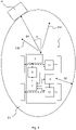
- Figure 1 shows an schematic overview of the steps of a method 101 for operating an automated guided vehicle 1.
- the automated guided vehicle 1 is schematically illustrated in figure 2 .
- the automated guided vehicle 1 is controlled by a control unit 7.
- the control unit 7 is communicatively coupled to a determining unit 5, a steering system 15, a braking system 9, and an electromotor 13.
- the determining unit 5 is communicatively coupled to a detection system 3, that is arranged for detecting an object 11 during movement of the automated guided vehicle 1.
- the detection system 3 comprises a number of 2D LiDAR scanners which allows the detection system 3 to detect the object 11 360 degrees around the automated guided vehicle 1.
- the determining unit 5 determines whether or not the detected object 11 is within a safety zone 21.
- the safety zone 21 is defined by a perimeter surrounding the automated guided vehicle 1.
- an angle ⁇ and a distance D1 of the object 11 to the automated guided vehicle 1 may be determined.
- the angle ⁇ and the distance D1 are compared to the safety zone 21 by the determining unit 5, in order to determine a possible collision.
- the safety zone 21 covers potential swept paths to which the control unit 7 may control the automated guided vehicle 1 during a safety stop of the automated guided vehicle 1.
- the automated guided vehicle 1 may be controlled towards a swept path in order to overcome a collision with the detected object 11, when the detected object is within the range of the safety zone 21.
- two potential swept paths 23A, 23B are shown.
- the shape and size of the safety zone 21 is related to the vehicle movement parameters, like the speed, the steering angle, the steering speed, and the braking distance of the automated guided vehicle 1, wherein a distance D2 of the perimeter of the safety zone 21 to the automated guided vehicle 1 varies along the perimeter.
- the control unit 7 controls the steering system 15 for steering the automated guided vehicle 1 to the appropriate direction.
- the appropriate direction may be a predetermined direction.
- the steering system 15 comprises a linear actuator for steering the automated guided vehicle 1 and a servomotor provided with an integrated encoder for powering the linear actuator.
- the control unit 7 controls the electromotor 13 for moving the automated guided vehicle 1, and controls the braking system 9 for stopping the automated guided vehicle 1.
- the control unit 7 controls the braking system 9 for performing a safety stop.
- the braking system 9 is communicatively coupled to the electromotor 13, such that the automated guided vehicle 1 is stopped solely by controlling the electromotor 13, during the safety stop.
- the control unit 7 comprises a processor and an internal memory, on which instructions are stored that allow the processor to execute the steps of the method 101 for operating an automated guided vehicle 1.
- one of the vehicle movement parameters of the automated guided vehicle 1 is determined by the control unit 7. Based on the determined vehicle movement parameter, the control unit 7 sets and/or adapts the safety zone 21 in the subsequent step of setting 105. The control unit 7 furthermore sets a maximum speed, and a maximum steering speed of the automated guided vehicle 1, based on the set or adapted safety zone 21.
- the angle ⁇ and the distance D1 of the object 11 to the automated guided vehicle 1 may be detected by the detection system 3 and compared to the safety zone 21.
- the angle ⁇ and the distance D1 of the detected object 11 to the automated guided vehicle may be determined by the determining unit 5, in order to determine that the object 11 is within the safety zone 21.
- the determining unit 5 After determining that the detected object 11 is within the safety zone 21, the determining unit 5 triggers the control unit 7 to control the braking system 9 of the automated guided vehicle 1 for performing the safety stop.
Landscapes
- Engineering & Computer Science (AREA)
- Physics & Mathematics (AREA)
- Aviation & Aerospace Engineering (AREA)
- Radar, Positioning & Navigation (AREA)
- Remote Sensing (AREA)
- General Physics & Mathematics (AREA)
- Automation & Control Theory (AREA)
- Optics & Photonics (AREA)
- Computer Vision & Pattern Recognition (AREA)
- Multimedia (AREA)
- Electromagnetism (AREA)
- Control Of Position, Course, Altitude, Or Attitude Of Moving Bodies (AREA)
Applications Claiming Priority (1)
| Application Number | Priority Date | Filing Date | Title |
|---|---|---|---|
| NL2028498A NL2028498B1 (en) | 2021-06-21 | 2021-06-21 | A method for operating an automated guided vehicle and an automated guided vehicle |
Publications (3)
| Publication Number | Publication Date |
|---|---|
| EP4109196A1 true EP4109196A1 (de) | 2022-12-28 |
| EP4109196B1 EP4109196B1 (de) | 2024-01-31 |
| EP4109196C0 EP4109196C0 (de) | 2024-01-31 |
Family
ID=77711388
Family Applications (1)
| Application Number | Title | Priority Date | Filing Date |
|---|---|---|---|
| EP22178829.2A Active EP4109196B1 (de) | 2021-06-21 | 2022-06-14 | Verfahren zum betrieb eines automatisch geführten fahrzeugs und automatisch geführtes fahrzeug |
Country Status (2)
| Country | Link |
|---|---|
| EP (1) | EP4109196B1 (de) |
| NL (1) | NL2028498B1 (de) |
Cited By (1)
| Publication number | Priority date | Publication date | Assignee | Title |
|---|---|---|---|---|
| DE102024100297A1 (de) | 2023-11-20 | 2025-05-22 | GM Global Technology Operations LLC | Dynamische und adaptive anpassung von ftf-geschwindigkeit und -abstand |
Citations (3)
| Publication number | Priority date | Publication date | Assignee | Title |
|---|---|---|---|---|
| EP3223098A1 (de) * | 2016-03-25 | 2017-09-27 | Panasonic Intellectual Property Corporation of America | Steuergerät, antriebssteuerungsverfahren und übergangsloses computerlesbares aufzeichnungsmedium zur speicherung eines programms |
| US20190160675A1 (en) * | 2017-11-27 | 2019-05-30 | Amazon Technologies, Inc. | Dynamic navigation of autonomous vehicle with safety infrastructure |
| EP3805891A1 (de) * | 2019-10-07 | 2021-04-14 | W. Gessmann GmbH | Fahrerloses transportfahrzeug für die innerbetriebliche warenlogistik |
-
2021
- 2021-06-21 NL NL2028498A patent/NL2028498B1/en active
-
2022
- 2022-06-14 EP EP22178829.2A patent/EP4109196B1/de active Active
Patent Citations (3)
| Publication number | Priority date | Publication date | Assignee | Title |
|---|---|---|---|---|
| EP3223098A1 (de) * | 2016-03-25 | 2017-09-27 | Panasonic Intellectual Property Corporation of America | Steuergerät, antriebssteuerungsverfahren und übergangsloses computerlesbares aufzeichnungsmedium zur speicherung eines programms |
| US20190160675A1 (en) * | 2017-11-27 | 2019-05-30 | Amazon Technologies, Inc. | Dynamic navigation of autonomous vehicle with safety infrastructure |
| EP3805891A1 (de) * | 2019-10-07 | 2021-04-14 | W. Gessmann GmbH | Fahrerloses transportfahrzeug für die innerbetriebliche warenlogistik |
Cited By (1)
| Publication number | Priority date | Publication date | Assignee | Title |
|---|---|---|---|---|
| DE102024100297A1 (de) | 2023-11-20 | 2025-05-22 | GM Global Technology Operations LLC | Dynamische und adaptive anpassung von ftf-geschwindigkeit und -abstand |
Also Published As
| Publication number | Publication date |
|---|---|
| NL2028498B1 (en) | 2022-12-29 |
| EP4109196B1 (de) | 2024-01-31 |
| EP4109196C0 (de) | 2024-01-31 |
Similar Documents
| Publication | Publication Date | Title |
|---|---|---|
| JP7255460B2 (ja) | 車両制御システム | |
| US20250026338A1 (en) | Control method for safe driving in zebra crossing intersection scene | |
| US9783197B2 (en) | Driving support device | |
| US9771070B2 (en) | Method and system for controlling a host vehicle | |
| JP7830143B2 (ja) | 車両の運転支援装置、及び、車両の運転支援システム | |
| US20170249836A1 (en) | Conflict-Resolution System For Operating An Automated Vehicle | |
| JP2023107674A (ja) | 車両の運転支援装置 | |
| JP2014197294A (ja) | 位置同定装置、及びそれを備えた移動ロボット | |
| KR20140033214A (ko) | 차량 원격 조작 시스템 및 차재기 | |
| US12589734B2 (en) | Method for dealing with obstacles in an industrial truck | |
| US20170305335A1 (en) | Indent-Indication System For An Automated Vehicle | |
| US20190258269A1 (en) | Vehicle control device | |
| CN112731920B (zh) | 搬运设备的控制方法、装置、搬运设备及存储介质 | |
| US20220266857A1 (en) | Vehicle control device, vehicle control method, and storage medium | |
| US20220105929A1 (en) | Method and Apparatus for Predicting Specification Motion of Other Vehicle | |
| RU2719083C1 (ru) | Способ для управления движением и устройство для управления движением транспортного средства | |
| KR20220115105A (ko) | 주차 보조 시스템 | |
| EP4109196A1 (de) | Verfahren zum betrieb eines automatisch geführten fahrzeugs und automatisch geführtes fahrzeug | |
| JP2023107672A (ja) | 車両の運転支援装置 | |
| WO2022144975A1 (ja) | 車両制御装置、車両制御方法、およびプログラム | |
| EP3640121A1 (de) | Fahrzeugspurhaltesystem und -verfahren | |
| JP2023107671A (ja) | 車両の運転支援装置 | |
| US20230267837A1 (en) | Traffic Control System and Traffic Control Method | |
| EP2808854B1 (de) | Fahrzeugsteuerungsvorrichtung | |
| US20190001227A1 (en) | Distributed and autonomous control system for guided-path vehicles |
Legal Events
| Date | Code | Title | Description |
|---|---|---|---|
| PUAI | Public reference made under article 153(3) epc to a published international application that has entered the european phase |
Free format text: ORIGINAL CODE: 0009012 |
|
| STAA | Information on the status of an ep patent application or granted ep patent |
Free format text: STATUS: THE APPLICATION HAS BEEN PUBLISHED |
|
| AK | Designated contracting states |
Kind code of ref document: A1 Designated state(s): AL AT BE BG CH CY CZ DE DK EE ES FI FR GB GR HR HU IE IS IT LI LT LU LV MC MK MT NL NO PL PT RO RS SE SI SK SM TR |
|
| STAA | Information on the status of an ep patent application or granted ep patent |
Free format text: STATUS: REQUEST FOR EXAMINATION WAS MADE |
|
| 17P | Request for examination filed |
Effective date: 20230116 |
|
| RBV | Designated contracting states (corrected) |
Designated state(s): AL AT BE BG CH CY CZ DE DK EE ES FI FR GB GR HR HU IE IS IT LI LT LU LV MC MK MT NL NO PL PT RO RS SE SI SK SM TR |
|
| STAA | Information on the status of an ep patent application or granted ep patent |
Free format text: STATUS: EXAMINATION IS IN PROGRESS |
|
| 17Q | First examination report despatched |
Effective date: 20230405 |
|
| P01 | Opt-out of the competence of the unified patent court (upc) registered |
Effective date: 20230527 |
|
| GRAP | Despatch of communication of intention to grant a patent |
Free format text: ORIGINAL CODE: EPIDOSNIGR1 |
|
| STAA | Information on the status of an ep patent application or granted ep patent |
Free format text: STATUS: GRANT OF PATENT IS INTENDED |
|
| INTG | Intention to grant announced |
Effective date: 20230929 |
|
| GRAS | Grant fee paid |
Free format text: ORIGINAL CODE: EPIDOSNIGR3 |
|
| GRAA | (expected) grant |
Free format text: ORIGINAL CODE: 0009210 |
|
| STAA | Information on the status of an ep patent application or granted ep patent |
Free format text: STATUS: THE PATENT HAS BEEN GRANTED |
|
| AK | Designated contracting states |
Kind code of ref document: B1 Designated state(s): AL AT BE BG CH CY CZ DE DK EE ES FI FR GB GR HR HU IE IS IT LI LT LU LV MC MK MT NL NO PL PT RO RS SE SI SK SM TR |
|
| REG | Reference to a national code |
Ref country code: GB Ref legal event code: FG4D Ref country code: CH Ref legal event code: EP |
|
| REG | Reference to a national code |
Ref country code: DE Ref legal event code: R096 Ref document number: 602022001761 Country of ref document: DE |
|
| REG | Reference to a national code |
Ref country code: IE Ref legal event code: FG4D |
|
| U01 | Request for unitary effect filed |
Effective date: 20240208 |
|
| U07 | Unitary effect registered |
Designated state(s): AT BE BG DE DK EE FI FR IT LT LU LV MT NL PT SE SI Effective date: 20240219 |
|
| P04 | Withdrawal of opt-out of the competence of the unified patent court (upc) registered |
Effective date: 20240214 |
|
| PG25 | Lapsed in a contracting state [announced via postgrant information from national office to epo] |
Ref country code: IS Free format text: LAPSE BECAUSE OF FAILURE TO SUBMIT A TRANSLATION OF THE DESCRIPTION OR TO PAY THE FEE WITHIN THE PRESCRIBED TIME-LIMIT Effective date: 20240531 |
|
| PG25 | Lapsed in a contracting state [announced via postgrant information from national office to epo] |
Ref country code: GR Free format text: LAPSE BECAUSE OF FAILURE TO SUBMIT A TRANSLATION OF THE DESCRIPTION OR TO PAY THE FEE WITHIN THE PRESCRIBED TIME-LIMIT Effective date: 20240501 |
|
| PG25 | Lapsed in a contracting state [announced via postgrant information from national office to epo] |
Ref country code: RS Free format text: LAPSE BECAUSE OF FAILURE TO SUBMIT A TRANSLATION OF THE DESCRIPTION OR TO PAY THE FEE WITHIN THE PRESCRIBED TIME-LIMIT Effective date: 20240430 Ref country code: HR Free format text: LAPSE BECAUSE OF FAILURE TO SUBMIT A TRANSLATION OF THE DESCRIPTION OR TO PAY THE FEE WITHIN THE PRESCRIBED TIME-LIMIT Effective date: 20240131 |
|
| PG25 | Lapsed in a contracting state [announced via postgrant information from national office to epo] |
Ref country code: ES Free format text: LAPSE BECAUSE OF FAILURE TO SUBMIT A TRANSLATION OF THE DESCRIPTION OR TO PAY THE FEE WITHIN THE PRESCRIBED TIME-LIMIT Effective date: 20240131 |
|
| PG25 | Lapsed in a contracting state [announced via postgrant information from national office to epo] |
Ref country code: RS Free format text: LAPSE BECAUSE OF FAILURE TO SUBMIT A TRANSLATION OF THE DESCRIPTION OR TO PAY THE FEE WITHIN THE PRESCRIBED TIME-LIMIT Effective date: 20240430 Ref country code: NO Free format text: LAPSE BECAUSE OF FAILURE TO SUBMIT A TRANSLATION OF THE DESCRIPTION OR TO PAY THE FEE WITHIN THE PRESCRIBED TIME-LIMIT Effective date: 20240430 Ref country code: IS Free format text: LAPSE BECAUSE OF FAILURE TO SUBMIT A TRANSLATION OF THE DESCRIPTION OR TO PAY THE FEE WITHIN THE PRESCRIBED TIME-LIMIT Effective date: 20240531 Ref country code: HR Free format text: LAPSE BECAUSE OF FAILURE TO SUBMIT A TRANSLATION OF THE DESCRIPTION OR TO PAY THE FEE WITHIN THE PRESCRIBED TIME-LIMIT Effective date: 20240131 Ref country code: GR Free format text: LAPSE BECAUSE OF FAILURE TO SUBMIT A TRANSLATION OF THE DESCRIPTION OR TO PAY THE FEE WITHIN THE PRESCRIBED TIME-LIMIT Effective date: 20240501 Ref country code: ES Free format text: LAPSE BECAUSE OF FAILURE TO SUBMIT A TRANSLATION OF THE DESCRIPTION OR TO PAY THE FEE WITHIN THE PRESCRIBED TIME-LIMIT Effective date: 20240131 |
|
| U20 | Renewal fee for the european patent with unitary effect paid |
Year of fee payment: 3 Effective date: 20240625 |
|
| PG25 | Lapsed in a contracting state [announced via postgrant information from national office to epo] |
Ref country code: PL Free format text: LAPSE BECAUSE OF FAILURE TO SUBMIT A TRANSLATION OF THE DESCRIPTION OR TO PAY THE FEE WITHIN THE PRESCRIBED TIME-LIMIT Effective date: 20240131 |
|
| PG25 | Lapsed in a contracting state [announced via postgrant information from national office to epo] |
Ref country code: PL Free format text: LAPSE BECAUSE OF FAILURE TO SUBMIT A TRANSLATION OF THE DESCRIPTION OR TO PAY THE FEE WITHIN THE PRESCRIBED TIME-LIMIT Effective date: 20240131 |
|
| PG25 | Lapsed in a contracting state [announced via postgrant information from national office to epo] |
Ref country code: SM Free format text: LAPSE BECAUSE OF FAILURE TO SUBMIT A TRANSLATION OF THE DESCRIPTION OR TO PAY THE FEE WITHIN THE PRESCRIBED TIME-LIMIT Effective date: 20240131 |
|
| PG25 | Lapsed in a contracting state [announced via postgrant information from national office to epo] |
Ref country code: CZ Free format text: LAPSE BECAUSE OF FAILURE TO SUBMIT A TRANSLATION OF THE DESCRIPTION OR TO PAY THE FEE WITHIN THE PRESCRIBED TIME-LIMIT Effective date: 20240131 |
|
| PG25 | Lapsed in a contracting state [announced via postgrant information from national office to epo] |
Ref country code: SK Free format text: LAPSE BECAUSE OF FAILURE TO SUBMIT A TRANSLATION OF THE DESCRIPTION OR TO PAY THE FEE WITHIN THE PRESCRIBED TIME-LIMIT Effective date: 20240131 |
|
| PG25 | Lapsed in a contracting state [announced via postgrant information from national office to epo] |
Ref country code: SM Free format text: LAPSE BECAUSE OF FAILURE TO SUBMIT A TRANSLATION OF THE DESCRIPTION OR TO PAY THE FEE WITHIN THE PRESCRIBED TIME-LIMIT Effective date: 20240131 Ref country code: SK Free format text: LAPSE BECAUSE OF FAILURE TO SUBMIT A TRANSLATION OF THE DESCRIPTION OR TO PAY THE FEE WITHIN THE PRESCRIBED TIME-LIMIT Effective date: 20240131 Ref country code: RO Free format text: LAPSE BECAUSE OF FAILURE TO SUBMIT A TRANSLATION OF THE DESCRIPTION OR TO PAY THE FEE WITHIN THE PRESCRIBED TIME-LIMIT Effective date: 20240131 Ref country code: CZ Free format text: LAPSE BECAUSE OF FAILURE TO SUBMIT A TRANSLATION OF THE DESCRIPTION OR TO PAY THE FEE WITHIN THE PRESCRIBED TIME-LIMIT Effective date: 20240131 |
|
| REG | Reference to a national code |
Ref country code: DE Ref legal event code: R097 Ref document number: 602022001761 Country of ref document: DE |
|
| PLBE | No opposition filed within time limit |
Free format text: ORIGINAL CODE: 0009261 |
|
| STAA | Information on the status of an ep patent application or granted ep patent |
Free format text: STATUS: NO OPPOSITION FILED WITHIN TIME LIMIT |
|
| 26N | No opposition filed |
Effective date: 20241101 |
|
| P05 | Withdrawal of opt-out of the competence of the unified patent court (upc) changed |
Free format text: CASE NUMBER: APP_8164/2024 Effective date: 20240219 |
|
| PG25 | Lapsed in a contracting state [announced via postgrant information from national office to epo] |
Ref country code: MC Free format text: LAPSE BECAUSE OF FAILURE TO SUBMIT A TRANSLATION OF THE DESCRIPTION OR TO PAY THE FEE WITHIN THE PRESCRIBED TIME-LIMIT Effective date: 20240131 |
|
| PG25 | Lapsed in a contracting state [announced via postgrant information from national office to epo] |
Ref country code: IE Free format text: LAPSE BECAUSE OF NON-PAYMENT OF DUE FEES Effective date: 20240614 |
|
| U20 | Renewal fee for the european patent with unitary effect paid |
Year of fee payment: 4 Effective date: 20250627 |
|
| PG25 | Lapsed in a contracting state [announced via postgrant information from national office to epo] |
Ref country code: CY Free format text: LAPSE BECAUSE OF FAILURE TO SUBMIT A TRANSLATION OF THE DESCRIPTION OR TO PAY THE FEE WITHIN THE PRESCRIBED TIME-LIMIT; INVALID AB INITIO Effective date: 20220614 |
|
| REG | Reference to a national code |
Ref country code: CH Ref legal event code: H13 Free format text: ST27 STATUS EVENT CODE: U-0-0-H10-H13 (AS PROVIDED BY THE NATIONAL OFFICE) Effective date: 20260127 |
|
| PG25 | Lapsed in a contracting state [announced via postgrant information from national office to epo] |
Ref country code: HU Free format text: LAPSE BECAUSE OF FAILURE TO SUBMIT A TRANSLATION OF THE DESCRIPTION OR TO PAY THE FEE WITHIN THE PRESCRIBED TIME-LIMIT; INVALID AB INITIO Effective date: 20220614 |
|
| PG25 | Lapsed in a contracting state [announced via postgrant information from national office to epo] |
Ref country code: CH Free format text: LAPSE BECAUSE OF NON-PAYMENT OF DUE FEES Effective date: 20250630 |