EP4109401A1 - Systèmes et procédés pour l'étalonnage d'une image synthétique sur un affichage avionique - Google Patents
Systèmes et procédés pour l'étalonnage d'une image synthétique sur un affichage avionique Download PDFInfo
- Publication number
- EP4109401A1 EP4109401A1 EP22172265.5A EP22172265A EP4109401A1 EP 4109401 A1 EP4109401 A1 EP 4109401A1 EP 22172265 A EP22172265 A EP 22172265A EP 4109401 A1 EP4109401 A1 EP 4109401A1
- Authority
- EP
- European Patent Office
- Prior art keywords
- faa
- image frame
- marking
- search region
- synthetic image
- Prior art date
- Legal status (The legal status is an assumption and is not a legal conclusion. Google has not performed a legal analysis and makes no representation as to the accuracy of the status listed.)
- Pending
Links
Images

Classifications
-
- G—PHYSICS
- G06—COMPUTING OR CALCULATING; COUNTING
- G06T—IMAGE DATA PROCESSING OR GENERATION, IN GENERAL
- G06T7/00—Image analysis
- G06T7/70—Determining position or orientation of objects or cameras
-
- B—PERFORMING OPERATIONS; TRANSPORTING
- B64—AIRCRAFT; AVIATION; COSMONAUTICS
- B64F—GROUND OR AIRCRAFT-CARRIER-DECK INSTALLATIONS SPECIALLY ADAPTED FOR USE IN CONNECTION WITH AIRCRAFT; DESIGNING, MANUFACTURING, ASSEMBLING, CLEANING, MAINTAINING OR REPAIRING AIRCRAFT, NOT OTHERWISE PROVIDED FOR; HANDLING, TRANSPORTING, TESTING OR INSPECTING AIRCRAFT COMPONENTS, NOT OTHERWISE PROVIDED FOR
- B64F5/00—Designing, manufacturing, assembling, cleaning, maintaining or repairing aircraft, not otherwise provided for; Handling, transporting, testing or inspecting aircraft components, not otherwise provided for
- B64F5/60—Testing or inspecting aircraft components or systems
-
- B—PERFORMING OPERATIONS; TRANSPORTING
- B64—AIRCRAFT; AVIATION; COSMONAUTICS
- B64D—EQUIPMENT FOR FITTING IN OR TO AIRCRAFT; FLIGHT SUITS; PARACHUTES; ARRANGEMENT OR MOUNTING OF POWER PLANTS OR PROPULSION TRANSMISSIONS IN AIRCRAFT
- B64D43/00—Arrangements or adaptations of instruments
-
- B—PERFORMING OPERATIONS; TRANSPORTING
- B64—AIRCRAFT; AVIATION; COSMONAUTICS
- B64D—EQUIPMENT FOR FITTING IN OR TO AIRCRAFT; FLIGHT SUITS; PARACHUTES; ARRANGEMENT OR MOUNTING OF POWER PLANTS OR PROPULSION TRANSMISSIONS IN AIRCRAFT
- B64D45/00—Aircraft indicators or protectors not otherwise provided for
- B64D45/04—Landing aids; Safety measures to prevent collision with earth's surface
- B64D45/08—Landing aids; Safety measures to prevent collision with earth's surface optical
-
- B—PERFORMING OPERATIONS; TRANSPORTING
- B64—AIRCRAFT; AVIATION; COSMONAUTICS
- B64D—EQUIPMENT FOR FITTING IN OR TO AIRCRAFT; FLIGHT SUITS; PARACHUTES; ARRANGEMENT OR MOUNTING OF POWER PLANTS OR PROPULSION TRANSMISSIONS IN AIRCRAFT
- B64D47/00—Equipment not otherwise provided for
- B64D47/02—Arrangements or adaptations of signal or lighting devices
- B64D47/06—Arrangements or adaptations of signal or lighting devices for indicating aircraft presence
-
- B—PERFORMING OPERATIONS; TRANSPORTING
- B64—AIRCRAFT; AVIATION; COSMONAUTICS
- B64D—EQUIPMENT FOR FITTING IN OR TO AIRCRAFT; FLIGHT SUITS; PARACHUTES; ARRANGEMENT OR MOUNTING OF POWER PLANTS OR PROPULSION TRANSMISSIONS IN AIRCRAFT
- B64D47/00—Equipment not otherwise provided for
- B64D47/08—Arrangements of cameras
-
- G—PHYSICS
- G06—COMPUTING OR CALCULATING; COUNTING
- G06N—COMPUTING ARRANGEMENTS BASED ON SPECIFIC COMPUTATIONAL MODELS
- G06N3/00—Computing arrangements based on biological models
- G06N3/02—Neural networks
- G06N3/04—Architecture, e.g. interconnection topology
- G06N3/0464—Convolutional networks [CNN, ConvNet]
-
- G—PHYSICS
- G06—COMPUTING OR CALCULATING; COUNTING
- G06N—COMPUTING ARRANGEMENTS BASED ON SPECIFIC COMPUTATIONAL MODELS
- G06N3/00—Computing arrangements based on biological models
- G06N3/02—Neural networks
- G06N3/08—Learning methods
-
- G—PHYSICS
- G06—COMPUTING OR CALCULATING; COUNTING
- G06N—COMPUTING ARRANGEMENTS BASED ON SPECIFIC COMPUTATIONAL MODELS
- G06N3/00—Computing arrangements based on biological models
- G06N3/02—Neural networks
- G06N3/08—Learning methods
- G06N3/09—Supervised learning
-
- G—PHYSICS
- G06—COMPUTING OR CALCULATING; COUNTING
- G06V—IMAGE OR VIDEO RECOGNITION OR UNDERSTANDING
- G06V20/00—Scenes; Scene-specific elements
- G06V20/50—Context or environment of the image
- G06V20/56—Context or environment of the image exterior to a vehicle by using sensors mounted on the vehicle
- G06V20/58—Recognition of moving objects or obstacles, e.g. vehicles or pedestrians; Recognition of traffic objects, e.g. traffic signs, traffic lights or roads
- G06V20/582—Recognition of moving objects or obstacles, e.g. vehicles or pedestrians; Recognition of traffic objects, e.g. traffic signs, traffic lights or roads of traffic signs
-
- G—PHYSICS
- G06—COMPUTING OR CALCULATING; COUNTING
- G06V—IMAGE OR VIDEO RECOGNITION OR UNDERSTANDING
- G06V20/00—Scenes; Scene-specific elements
- G06V20/50—Context or environment of the image
- G06V20/56—Context or environment of the image exterior to a vehicle by using sensors mounted on the vehicle
- G06V20/58—Recognition of moving objects or obstacles, e.g. vehicles or pedestrians; Recognition of traffic objects, e.g. traffic signs, traffic lights or roads
- G06V20/584—Recognition of moving objects or obstacles, e.g. vehicles or pedestrians; Recognition of traffic objects, e.g. traffic signs, traffic lights or roads of vehicle lights or traffic lights
-
- G—PHYSICS
- G06—COMPUTING OR CALCULATING; COUNTING
- G06V—IMAGE OR VIDEO RECOGNITION OR UNDERSTANDING
- G06V20/00—Scenes; Scene-specific elements
- G06V20/50—Context or environment of the image
- G06V20/56—Context or environment of the image exterior to a vehicle by using sensors mounted on the vehicle
- G06V20/58—Recognition of moving objects or obstacles, e.g. vehicles or pedestrians; Recognition of traffic objects, e.g. traffic signs, traffic lights or roads
- G06V20/586—Recognition of moving objects or obstacles, e.g. vehicles or pedestrians; Recognition of traffic objects, e.g. traffic signs, traffic lights or roads of parking space
-
- G—PHYSICS
- G06—COMPUTING OR CALCULATING; COUNTING
- G06V—IMAGE OR VIDEO RECOGNITION OR UNDERSTANDING
- G06V20/00—Scenes; Scene-specific elements
- G06V20/50—Context or environment of the image
- G06V20/56—Context or environment of the image exterior to a vehicle by using sensors mounted on the vehicle
- G06V20/588—Recognition of the road, e.g. of lane markings; Recognition of the vehicle driving pattern in relation to the road
-
- G—PHYSICS
- G06—COMPUTING OR CALCULATING; COUNTING
- G06T—IMAGE DATA PROCESSING OR GENERATION, IN GENERAL
- G06T2207/00—Indexing scheme for image analysis or image enhancement
- G06T2207/10—Image acquisition modality
- G06T2207/10016—Video; Image sequence
-
- G—PHYSICS
- G06—COMPUTING OR CALCULATING; COUNTING
- G06T—IMAGE DATA PROCESSING OR GENERATION, IN GENERAL
- G06T2207/00—Indexing scheme for image analysis or image enhancement
- G06T2207/20—Special algorithmic details
- G06T2207/20084—Artificial neural networks [ANN]
Definitions
- the following disclosure generally relates to flight display systems. More particularly, the following disclosure relates to systems and methods for calibrating a synthetic image on an avionic display.
- the synthetic vision display (for example, on a head-up display (HUD)) that a pilot relies on when operating an aircraft near an airport is generated by referencing stored information about features at the airport (airport features) and their respective locations.
- the synthetic vision images on the synthetic vision display are constructed as a function of the aircraft position, orientation, and attitude.
- the airport features include signs, runway/taxiway centerlines, outlines, hold short lines, and the like. Each of these airport features has associated therewith a specific FAA marking.
- a technical problem can occur when the synthetic vision display on an avionic display, renders the FAA markings for the airport, and the markings are offset, and do not match what the pilot sees in the real world.
- the offsets can be distracting to the pilot; even an offset of just a couple of feet can result in a noticeable mismatch from the pilot's real-world view.
- a method for calibrating a synthetic image on an avionic display in a cockpit of an aircraft including: at a controller circuit, receiving a synthetic image frame generated by an avionic display module, the synthetic image frame being forward-facing and depicting airport features surrounding an aircraft position and location; receiving a sensor image frame depicting airport features surrounding the aircraft position and location, the sensor image frame being generated by a forward-facing sensor system on the aircraft; performing object recognition on the sensor image frame to generate a first search region for a first Federal Aviation Administration (FAA) marking, defined as a first search region-FAA marking pair; processing the sensor image frame and the first search region-FAA marking pair using a deep learning method (DLM) to determine for the first FAA marking of the first search region-FAA marking pair, each of: a position deviation calculation, an orientation deviation calculation, and a synthetic image distortion factor; updating the synthetic image frame, in accordance with the position deviation calculation, the orientation deviation calculation, and the synthetic image distortion factor, thereby calibrating the synthetic image frame; and rendering the updated synthetic image frame
- a system for calibrating a synthetic image on an avionic display in a cockpit of an aircraft including: a controller circuit configured by programming instructions to, receive a synthetic image frame generated by an avionic display module, the synthetic image frame being forward-facing and depicting airport features surrounding the aircraft position and location; receive a sensor image frame depicting airport features surrounding the aircraft position and location, the sensor image frame being generated by a forward-facing sensor system on the aircraft; perform object recognition on the sensor image frame to generate a first search region for a first Federal Aviation Administration (FAA) marking, defined as a first search region-FAA marking pair; process the sensor image frame and the first search region-FAA marking pair using a deep learning method (DLM) to determine for the first FAA marking of the first search region-FAA marking pair, each of: a position deviation calculation, an orientation deviation calculation, and a synthetic image distortion factor; update the synthetic image frame, in accordance with the position deviation calculation, the orientation deviation calculation, and the synthetic image distortion factor, thereby calibrating the synthetic image frame; and
- DLM deep
- a system for calibrating a synthetic image on an avionic display in a cockpit of an aircraft includes: an object detection module configured to: receive a sensor image frame depicting airport features surrounding the aircraft position and location, the sensor image frame being generated by a forward-facing sensor system on the aircraft; and perform object recognition on the sensor image frame to generate a first search region for a first Federal Aviation Administration (FAA) marking, defined as a first search region-FAA marking pair; and a position correcting module operationally coupled to the object detection module and configured to process the sensor image frame, synthetic image frame, and the first search region-FAA marking pair using a deep learning method (DLM) to determine for the first FAA marking of the first search region-FAA marking pair, each of: a position deviation calculation, an orientation deviation calculation, and a synthetic image distortion factor; and an image updating module configured to: receive the position deviation calculation, the orientation deviation calculation, and the synthetic image distortion factor; receive a synthetic image frame generated by an avionic display module, the synthetic image frame being forward-facing
- FAM Federal Aviation Administration
- Embodiments of the present disclosure may be described herein in terms of functional and/or logical block components and various processing steps. It should be appreciated that such block components may be realized by any number of hardware, software, and/or firmware components configured to perform the specified functions. For example, an embodiment of the present disclosure may employ various integrated circuit components, e.g., memory elements, digital signal processing elements, logic elements, programmable logic arrays, application specific integrated circuits, look-up tables, or the like, which may carry out a variety of functions under the control of one or more microprocessors or other control devices.
- integrated circuit components e.g., memory elements, digital signal processing elements, logic elements, programmable logic arrays, application specific integrated circuits, look-up tables, or the like, which may carry out a variety of functions under the control of one or more microprocessors or other control devices.
- integrated circuit components e.g., memory elements, digital signal processing elements, logic elements, programmable logic arrays, application specific integrated circuits, look-up tables, or the like, which
- the synthetic images presented on a head-up display (HUD) (or other synthetic display) in an aircraft are generated by referencing stored information about the airport features and using them to construct synthetic vision images as a function of the aircraft position, orientation, and attitude.
- HUD head-up display
- For various phases of flight operations, such as approach, landing, and taxing the pilot relies on locations of specific airport features, which are identified with associated FAA markings. Examples of these features that have associated FAA markings include signs, runway/taxiway centerlines, outlines, hold short lines, and the like.
- Synthetically generated features presented at correct locations on a display greatly helps the tasks of navigating within an airport environment in these low visibility or night conditions.
- a technical problem is presented when the synthetic vision display, renders the FAA markings for an airport, and the FAA markings are offset from, and do not match, what the pilot sees in the real world.
- the offsets can be distracting to the pilot during a cognitively demanding time; even an offset of just a couple of feet can result in a noticeable mismatch from the pilot's real-world view.
- the mismatch reduces pilot ability and confidence to use the system in low visibility conditions.
- Proposed embodiments use a Deep Learning Method (DLM) to train an object detection model to detect objects (features) associated with FAA markings in a forward-facing view sensor image.
- DLM Deep Learning Method
- Proposed embodiments employ the DLM in the determination of a position difference and an orientation difference (the aforementioned "offsets"), and perceived distortions between objects detected in the sensor image and the same synthetic object in a HUD that was generated from a preloaded airport features database.
- the determined position difference, orientation difference, and distortion corrections are used to calibrate the HUD view, with the objective and result of rendering the synthetic vision image such that the airport markings and signs match to the real-world objects viewed through the HUD
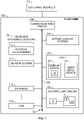
- FIG. 1 is a block diagram of a system for calibrating a synthetic image on an avionic display in an aircraft (shortened herein to "system” 102 ), in accordance with an exemplary and non-limiting embodiment of the present disclosure.
- the system 102 may be utilized onboard a mobile platform to provide calibration of displayed synthetic images, as described herein.
- the mobile platform is an aircraft 100 , which carries or is equipped with the system 102.
- Aircraft 100 may be any type of vehicle that can travel through the air ( i . e ., without physical contact with terrain or water).
- aircraft 100 may be any type of airplane (regardless of size or propulsion means, ranging from large, turbine-powered commercial airplanes to small, electrically-powered drones), rotorcraft (helicopter, gyrocopter), lighter-than-air vessel (hot-air balloon, blimp), or glider, for example.
- Aircraft 100 may be "manned" in the conventional sense that the flight crew is present within the aircraft 100 , or it may be manned remotely.
- system 102 includes the following components or subsystems, each of which may assume the form of a single device or multiple interconnected devices: a controller circuit 104 operationally coupled to: a HMI 106 (human-machine interface); a communications circuit 108 ; an avionic display system 114 ; and one or more on-board systems and sensors 30.
- the controller circuit 104 communicates with the other components of the system 102 via a communication bus 105.
- the human-machine interface, HMI 106 may include a display device 20 and a user input device 24.
- the HMI 106 includes at least one instance of an integration of the user input device 24 and a display device 20 (e.g., a touch screen display).
- the HMI 106 may include a user input device 24 such as, any combination of a keyboard, cursor control device, voice input device, gesture input apparatus, or the like.
- the avionic display system 114 is configured to receive and process information from various aircraft systems and databases (supplied via the communication bus 105 ), perform display processing and graphics processing, and to drive the display device 20 to render features in one or more avionic displays 22.
- the term "avionic display” is defined as synonymous with the term “aircraft-related display” and "cockpit display” and encompasses displays generated in textual, graphical, cartographical, and other formats.
- the avionic display 22 is a primary flight display (PFD) or a navigation display.
- the avionic display 22 can be, or include, any of various types of lateral displays and vertical situation displays on which map views and symbology, text annunciations, and other graphics pertaining to flight planning are presented for a pilot to view.
- the avionic display 22 generated and controlled by the system 102 can include graphical user interface (GUI) objects and alphanumerical input displays of the type commonly presented on the screens of MCDUs, as well as Control Display Units (CDUs) generally.
- GUI graphical user interface
- CDUs Control Display Units
- avionic displays 22 include one or more two dimensional (2D) avionic displays, such as a horizontal (i.e., lateral) navigation display or vertical navigation display; and/or on one or more three dimensional (3D) avionic displays, such as a Primary Flight Display (PFD) or an exocentric 3D avionic display.
- the avionic display includes a synthetic vision display.
- the display device 20 is configured to include any number and type of image generating devices on which one or more avionic displays 22 may be produced.
- the display device 20 may embody a touch screen display.
- display device 20 may be affixed to the static structure of the Aircraft cockpit as, for example, the aforementioned Head Up Display (HUD) unit, or a Head Down Display (HDD).
- display device 20 may assume the form of a movable display device (e.g., a pilot-worn display device) or a portable display device, such as an Electronic Flight Bag (EFB), a laptop, or a tablet computer carried into the Aircraft cockpit by a pilot.
- EFB Electronic Flight Bag
- the HMI 106 further includes or has integrated therein an audio system capable of emitting speech and sounds, as well as of receiving speech input.
- the HMI 106 may include any of: a graphical user interface (GUI), a speech recognition system, and a gesture recognition system.
- GUI graphical user interface
- the controller circuit 104 and avionics display system 114 may command and control the generation, by the HMI 106 , of a variety of graphical user interface (GUI) objects or elements described herein, including, for example, buttons, sliders, and the like, which are used to prompt a user to interact with the human-machine interface to provide user input, and to activate respective functions and provide user feedback, responsive to received user input at the GUI element.
- GUI graphical user interface
- the on-board systems and sensors 30 generally include a position-determining system 110 , a sensor system 112 , a database 116 , and a flight management system (FMS) 120.
- FMS flight management system
- the position-determining system 110 may include a variety of sensors and performs the function of measuring and supplying various types of aircraft status data and measurements to controller circuit 104 and other aircraft systems (via the communication bus 105 ) during aircraft flight.
- the aircraft status data includes, without limitation, one or more of: inertial reference system measurements providing a location, Flight Path Angle (FPA) measurements, airspeed data, groundspeed data (including groundspeed direction), vertical speed data, vertical acceleration data, altitude data, attitude data including pitch data and roll measurements, yaw data, heading information, sensed atmospheric conditions data (including wind speed and direction data), flight path data, flight track data, radar altitude data, and geometric altitude data.
- FPA Flight Path Angle
- the position-determining system 110 may be realized as one or more of a global positioning system (GPS), inertial reference system (IRS), or a radio-based navigation system (e.g., VHF omni-directional radio range (VOR) or long-range aid to navigation (LORAN)), and it may include one or more navigational radios or other sensors suitably configured to support operation of the aircraft 100.
- GPS global positioning system
- IRS inertial reference system
- LORAN long-range aid to navigation
- the position-determining system 110 may also obtain and/or determine the heading of the aircraft 100 (i . e ., the direction that aircraft 100 is traveling relative to some reference) using a magnet compass or a magnetometer, for example.
- the position-determining system 110 may also include a barometric altimeter such that the position of the aircraft 100 may be additionally determined with reference to a barometric altitude.
- the GPS may alternatively or additionally provide altitude information as part of the position-determining system 110.
- the position-determining system 110 is capable of obtaining and/or determining the instantaneous position and altitude of the aircraft 100 , and the position-determining system 110 generates aircraft status data for the aircraft, including the current location of the aircraft 100 ( e.g ., the latitude and longitude) and the altitude and heading of the aircraft 100.
- the position-determining system 110 may provide this aircraft status data to the controller circuit 104 and the flight management system 120 to support their operation, as described herein.
- the sensor system 112 is a forward-facing sensor system mounted on the mobile platform 100 , configured to obtain real-time sensor images. During aircraft operation at an airport, the sensor system 112 provides a sensor image frame depicting airport features surrounding the aircraft position and location. Non-limiting examples of the sensor system 112 include a camera, EVS Infrared, and millimeter wave system. In some embodiments, the sensor system 112 includes a camera and associated circuitry, and the sensor image frame is then a camera image frame. In various embodiments, output from the sensor system 112 additionally includes a frame rate.
- the database 116 may be realized as one or more different onboard databases, each being a computer-readable storage media or memory.
- the database 116 stores two- or three-dimensional map data, including airport features data, geographical (terrain), buildings, bridges, and other structures, street maps, and navigational databases, which may be updated on a periodic or iterative basis to ensure data timeliness.
- the system 102 utilizes a storage of Federal Aviation Administration (FAA) markings, described in more detail below.
- the FAA markings may be stored in the database 116.
- the data stored in the database 116 may be uploaded into the database 116 at an initialization step and then periodically updated, as directed by either a program update or by an externally triggered update.
- FAA Federal Aviation Administration
- Flight management system 120 provides the primary navigation, flight planning, and route determination and en route guidance for the aircraft 100.
- the flight management system 120 may contribute aircraft status data provided to controller circuit 104 , such as, the aircraft's current position, attitude, orientation, and flight direction (e.g ., heading, course, track, etc .), the aircraft's airspeed, ground speed, altitude ( e.g ., relative to sea level), pitch, and other important flight information if such information is desired.
- flight management system 120 may include any suitable position and direction determination devices that are capable of providing controller circuit 104 with at least an aircraft's current position (e.g., in latitudinal and longitudinal form), the real-time direction (heading, course, track, etc .) of the aircraft in its flight path, and other important flight information (e.g ., airspeed, altitude, pitch, attitude, etc .). Flight management system 120 and controller circuit 104 cooperate to guide and control aircraft 100 during all phases of operation, as well as to provide other systems of aircraft 100 with flight data generated or derived from flight management system 120.
- flight management system 120 and controller circuit 104 cooperate to guide and control aircraft 100 during all phases of operation, as well as to provide other systems of aircraft 100 with flight data generated or derived from flight management system 120.
- aircraft 100 includes many more additional features (systems, databases, etc .) than the illustrated systems 106 - 120. For purposes of simplicity of illustration and discussion, however, the illustrated aircraft 100 omits these additional features.
- External sources 50 may include a weather subscription service, other subscription service, traffic monitoring service, neighbor traffic, air traffic control (ATC), ground stations, and the like.
- ATC air traffic control
- controller circuit broadly encompasses those components utilized to carry-out or otherwise support the processing functionalities of the system 102. Accordingly, in various embodiments, the controller circuit 104 can be implemented as a programmable logic array, application specific integrated circuit, system on a chip (SOC), or other similar firmware, as well as by a combination of any number of dedicated or shared processors, flight control computers, navigational equipment pieces, computer-readable storage devices (including or in addition to memory 7 ), power supplies, storage devices, interface cards, and other standardized components.
- SOC system on a chip
- the controller circuit 104 is realized as an enhanced computer system, having one or more processors 5 operationally coupled to computer-readable storage media or memory 7 , having stored therein at least one novel firmware or software program (generally, computer-readable instructions that embody an algorithm) for carrying-out the various process tasks, calculations, and control/display functions described herein.
- the memory 7 may include volatile and nonvolatile storage in read-only memory (ROM), random-access memory (RAM), and keep-alive memory (KAM), for example.
- KAM is a persistent or non-volatile memory that may be used to store various operating variables while the processor 5 is powered down.
- the memory 7 may be implemented using any of a number of known memory devices such as PROMs (programmable read-only memory), EPROMs (electrically PROM), EEPROMs (electrically erasable PROM), flash memory, or any other electric, magnetic, optical, or combination memory devices capable of storing data, some of which represent executable instructions, used by the processor 5.
- PROMs programmable read-only memory
- EPROMs electrically PROM
- EEPROMs electrically erasable PROM
- flash memory or any other electric, magnetic, optical, or combination memory devices capable of storing data, some of which represent executable instructions, used by the processor 5.
- the controller circuit 104 may be programmed with and execute the at least one firmware or software program (for example, program 9 and deep learning method (DLM) 11 , described in more detail below) that embodies an algorithm for receiving, processing, enabling, generating, updating and rendering, described herein, to thereby perform the various process steps, tasks, calculations, and control/display functions described herein.
- firmware or software program for example, program 9 and deep learning method (DLM) 11 , described in more detail below
- DLM deep learning method
- Controller circuit 104 may exchange data, including real-time wireless data, with one or more external sources 50 to support operation of the system 102 in embodiments.
- the controller circuit 104 may utilize the communications bus 105 and communications circuit 108.
- the communications circuit 108 includes the hardware and software to support one or more communication protocols for wireless communication between the processor 5 and external sources, such as satellites, the cloud, communication towers and ground stations.
- the communications circuit 108 supports wireless data exchange over a communications network, such as a public or private network implemented in accordance with Transmission Control Protocol/Internet Protocol architectures or other conventional protocol standards. Encryption and mutual authentication techniques may be applied, as appropriate, to ensure data security.
- the communications circuit 108 supports communication with technicians, and/or one or more storage interfaces for direct connection to storage apparatuses.
- the communications circuit 108 is integrated within the controller circuit 104.
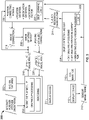
- each module in FIG. 2 represents a processing block of software (e.g., program 9 and DLM 11 ) that is configured to cause the processor 5 to perform the tasks/processes described herein.
- software e.g., program 9 and DLM 11
- An avionic display module 202 receives aircraft position, attitude and orientation data, accesses the aircraft features database 116, performs the aforementioned display processing and graphics processing, and generates commands and controls to drive the display device 20 to render features in one or more avionic displays 22 , as is conventional.
- the output generated by the avionic display module 202 is a synthetic image frame 218.
- the synthetic image frame 218 may be rendered directly by the display device 20.
- the present invention converts the synthetic image frame 218 into an improved image frame, in that it utilizes sensor image frames 212 provided by an on-board sensor system 112 to calibrate the synthetic image frame 218 , as follows.
- An object detection module 204 embodies the object detection model introduced earlier and is configured to receive and operate on the sensor image frame 212.
- the object detection model includes or is integrated with a storage of FAA markings 210.
- the FAA markings are the aforementioned industry standard airport markings for runways, taxiways, and aprons, hold lines, for example, as can be found in FAA Advisory Circular 150/5340-1M.
- the object detection module 204 performs the processes of searching the sensor image frame to identify a FAA marking therein, and upon finding an FAA marking therein, the object detection module 204 generates a search region-FAA marking pair 214.
- the search region-FAA marking pair 214 is a narrowed-down area, or focus area, to be further processed to locate the object/feature associated with the FAA marking more accurately.
- the object detection module 204 identifies more than one respective FAA marking in the sensor image frame, and responsive thereto, generates a respective more than one search region-FAA marking pair 214.
- the object detection module 204 performs a pre-process localization prior to generating the search region-FAA marking pair 214.
- Pre-process localization means a process of sub-dividing the sensor image frame 212 into a pre-programmed number of areas or regions (e.g., four quadrants), and then separately and concurrently searching each of the regions or quadrants for FAA markings.
- the object detection module 204 generates the search region-FAA marking pair 214 by additionally applying a prioritization scheme to one or more FAA markings identified in the sensor image frame, and only a FAA marking that exceeds a pre-programmed priority threshold results in the output search region-FAA marking pair 214.
- the prioritization scheme can be separately applied to each of one or more regions or quadrants.
- a position correcting module 206 may receive as input the search region-FAA marking pair, the sensor image frame 21 , and the synthetic image frame 218 , and perform the process of determining or generating at least one image correction 216 based on this input.
- the image correction 216 includes a position deviation, wherein a position deviation is a cartesian or X-Y difference between the FAA marking position.
- an image correction 216 may include an angular rotation in degrees.
- a 2D (i.e., cartesian) position of the FAA marking outline in the image is used to calculate the position deviation between the sensor image frame 212 and the synthetic image frame 218.
- a maximum position deviation is identified based on an integrity requirement of the system 102 , which means when the calculated position deviation exceeds this maximum position deviation, the respective FAA marking should not be used to calibrate the synthetic image on the avionic display. This is to ensure that the system 102 integrity not be impacted by the calibration.
- the image correction 216 includes an orientation deviation, wherein an orientation deviation is an angular or rotational difference in the FAA marking position.
- the image correction 216 includes a distortion factor, wherein a distortion factor is a correction for a sub-area in an image to account for that sub-area having a different scaling, compression, or shifting of image elements/objects compared to other subareas making up the entire image area.
- the image correction 216 includes two or more of: a position deviation, an orientation deviation, and a distortion factor.
- the processor 5 harnesses the power of artificial intelligence (AI) and machine learning (ML) or a Deep Learning Method (DLM) 225.
- the DLM 225 may be employed to train the object detection model to detect the objects/features associated with FAA markings (the airport markings and signs, such as runway/taxiway centerlines, outlines, hold shorts, etc.) from images provided by the forward-facing sensor system 112.
- image corrections can be determined, and the synthetic image on an avionic display in a cockpit of an aircraft (e.g., HUD view) can be calibrated based on those image corrections.
- the goal or target of the system 102 is to render the synthetic vision airport FAA markings and signs such that they match the real-world objects viewed through HUD.
- the synthetic image calibrated, and learned parameters/behaviors from the DLM
- the subsequent synthetic image display is mostly error-free with respect to the perceived real world object positions.
- the DLM 225 once trained, advantageously provides near real-time feedback related to position and orientation deviations and distortion. The use of the DLM 225 saves computational time, reduces cycle time, and provides high utility high integrity, real-time feedback.
- the position correcting module 206 identifies an object/feature in the sensor image frame, and determines an object position for the object, as a function of a predefined set of rules encoded in the program 9.
- rendering the updated synthetic image frame 220 further includes (i) using the object position to visually distinguish the object within the updated synthetic image frame, and (ii) deleting a synthetic rendering of the object in the updated synthetic image frame.
- the DLM 225 may be implemented in various commercially available ways.
- the DLM 225 can be a Region based Convolutional Neural Networks (R-CNN), Single Shot Detector (SSD), or YOLO.
- the DLM 225 is a convolutional neural network (CNN) with multiple hidden convolution layers.
- CNN convolutional neural network
- An image updating module 208 may be configured to receive the synthetic image frame 218 , from the avionic display module 202 , and perform an updating process as a function of the image correction 216. In various embodiments, the image updating module 208 performs the updating process locally, meaning that each region or quadrant is separately and independently updated. At the completion of the image updating process, an updated synthetic image frame 220 is generated. The updated synthetic image frame 220 may be provided back to the avionic display module 202 , which, responsive thereto, will perform graphics processing render the updated synthetic image frame 220 on the display device 20. The updated synthetic image frame 220 is a calibrated synthetic image for the avionic display in the cockpit of the aircraft.
- method 300 for calibrating a synthetic image on an avionic display in a cockpit of an aircraft is described, in accordance with exemplary embodiments of the present disclosure.
- the following description of method 300 may refer to elements mentioned above in connection with FIGS. 1-2 .
- portions of method 300 may be performed by different components of the described system.
- method 300 may include any number of additional or alternative tasks, the tasks shown in FIG. 3 need not be performed in the illustrated order, and method 300 may be incorporated into a more comprehensive procedure or method having additional functionality not described in detail herein.
- one or more of the tasks shown in FIG. 3 could be omitted from an embodiment of the method 300 as long as the intended overall functionality remains intact.
- the avionic display module 202 is generating the synthetic image frame 218 described above. In doing so, the avionic display module 202 is receiving aircraft position, attitude, and orientation information, such as from the position-determining system 110 , and is also referencing a storage of aircraft features 222.
- the system 102 receives a sensor image frame 212. As mentioned, in various embodiments, the sensor image frame 212 is a camera frame.
- the system 102 may execute the trained DLM 225 to perform object detection and to calculate one or more image corrections 216.
- image corrections 216 may be a combination of a position deviation, an orientation deviation, and a distortion factor.
- the system 102 performs the task of updating the synthetic image frame 218 as a function of the one or more image corrections 216.
- the system 102 performs the task of rendering the updated synthetic image frame 220 on the display device 20.
- the method 300 can keep cycling from 310 back to 302 until the aircraft lands.
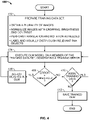
- FIG. 4 provides an example method for training the DLM 225 , when the DLM 225 is implemented as a CNN.
- a training data set is developed.
- the training data set includes a plurality of sensor images taken from the sensor system 112 , each sensor image including one or more FAA markings. In an example, there are 20 to 50 thousand images, or members, of the training data set.
- the images are normalized to make them suitable for comparison. Normalizing includes cropping the images to be focused on the relevant FAA markings, and potentially adjusting contrast and brightness, lower visibility induced image feature degradations, adjustment of field of views matching typical aircraft installations, movement and vibration induced image feature smearing.
- Images may also have to be translated and/or rotated to account for a perspective that is a function of the mounting of the sensor system 112 on the aircraft.
- the FAA markings in the training data images are visually distinguished (e.g., highlighted) and labeled.
- the CNN is trained using a validation data set that is the same as the training data set.
- the DLM 225 is executed on a member of the training data set, generating a training error.
- the training error is compared to a threshold, and if the training error exceeds the threshold, weights in the DLM 225 may be adjusted at 408 before returning to 404 to execute the DLM again.
- the method proceeds to check whether there is another member of the training data set available at 410.
- the method 400 proceeds to execute the DLM on the next member at 404. Steps 404-410 are performed for all the members of the training data set, and when there are no more members, at 410 , the trained DLM 225 is saved at 412.
- one pass over the complete training data set is called an epoch, in each epoch, a training error is generated, and the CNN is trained by comparing the training error to an error threshold and backpropagating when the training error exceeds the error threshold.
- Backpropagating includes adjusting weights in neurons of an encoder in the CNN based on a comparison of the training error to its previous value.
- the present disclosure has provided several embodiments of systems and methods for calibrating a synthetic image on an avionic display.
- Proposed embodiments use a Deep Learning Method (DLM) to train an object detection model to detect FAA markings in a forward-facing view sensor image.
- Proposed embodiments determine a position difference and an orientation difference and use the determined position difference and orientation difference to calibrate the HUD view.
- the synthetic vision image is rendered such that the airport markings and signs match to the real-world objects viewed through the HUD
- the disclosed systems and methods provide an objectively improved HMI over available avionics display systems.
- DLM Deep Learning Method
Landscapes
- Engineering & Computer Science (AREA)
- Physics & Mathematics (AREA)
- Theoretical Computer Science (AREA)
- Aviation & Aerospace Engineering (AREA)
- General Physics & Mathematics (AREA)
- Multimedia (AREA)
- Biophysics (AREA)
- Mathematical Physics (AREA)
- Data Mining & Analysis (AREA)
- Evolutionary Computation (AREA)
- General Health & Medical Sciences (AREA)
- Molecular Biology (AREA)
- Computing Systems (AREA)
- General Engineering & Computer Science (AREA)
- Biomedical Technology (AREA)
- Computational Linguistics (AREA)
- Software Systems (AREA)
- Artificial Intelligence (AREA)
- Life Sciences & Earth Sciences (AREA)
- Health & Medical Sciences (AREA)
- Manufacturing & Machinery (AREA)
- Transportation (AREA)
- Computer Vision & Pattern Recognition (AREA)
- Traffic Control Systems (AREA)
- Electrochromic Elements, Electrophoresis, Or Variable Reflection Or Absorption Elements (AREA)
Applications Claiming Priority (1)
| Application Number | Priority Date | Filing Date | Title |
|---|---|---|---|
| US17/332,236 US11851215B2 (en) | 2021-05-27 | 2021-05-27 | Systems and methods for calibrating a synthetic image on an avionic display |
Publications (1)
| Publication Number | Publication Date |
|---|---|
| EP4109401A1 true EP4109401A1 (fr) | 2022-12-28 |
Family
ID=81595862
Family Applications (1)
| Application Number | Title | Priority Date | Filing Date |
|---|---|---|---|
| EP22172265.5A Pending EP4109401A1 (fr) | 2021-05-27 | 2022-05-09 | Systèmes et procédés pour l'étalonnage d'une image synthétique sur un affichage avionique |
Country Status (3)
| Country | Link |
|---|---|
| US (1) | US11851215B2 (fr) |
| EP (1) | EP4109401A1 (fr) |
| IL (1) | IL292412B2 (fr) |
Families Citing this family (1)
| Publication number | Priority date | Publication date | Assignee | Title |
|---|---|---|---|---|
| CN117611971A (zh) * | 2023-12-04 | 2024-02-27 | 中国民航大学 | 一种面向民机可视导航的场面多尺度目标检测方法 |
Family Cites Families (38)
| Publication number | Priority date | Publication date | Assignee | Title |
|---|---|---|---|---|
| US6898331B2 (en) * | 2002-08-28 | 2005-05-24 | Bae Systems Aircraft Controls, Inc. | Image fusion system and method |
| US7382288B1 (en) * | 2004-06-30 | 2008-06-03 | Rockwell Collins, Inc. | Display of airport signs on head-up display |
| US7605774B1 (en) * | 2004-07-02 | 2009-10-20 | Rockwell Collins, Inc. | Enhanced vision system (EVS) processing window tied to flight path |
| DE102005053899A1 (de) * | 2005-11-09 | 2007-05-10 | Vaisala Gmbh | Verfahren zur Bestimmung einer optimalen Landebahnbefeuerungsintensität |
| US7924172B1 (en) | 2007-08-24 | 2011-04-12 | Rockwell Collins, Inc. | Synthetic vision runway corrective update system |
| EP2232463B1 (fr) | 2007-11-30 | 2018-04-11 | Searidge Technologies INC. | Système de suivi de cible d'aéroport |
| CA2721662C (fr) * | 2008-04-16 | 2016-06-07 | Elbit Systems Ltd. | Systeme de vision optimise multispectral et procede d'atterrissage d'aeronef dans des conditions meteorologiques non favorables |
| US8089375B1 (en) * | 2008-06-09 | 2012-01-03 | Rockwell Collins, Inc. | Head-up display/synthetic vision system predicted flight path depiction |
| US8170729B2 (en) * | 2008-08-08 | 2012-05-01 | Honeywell International Inc. | Method and system for operating a display device on-board an aircraft |
| US10091439B2 (en) * | 2009-06-03 | 2018-10-02 | Flir Systems, Inc. | Imager with array of multiple infrared imaging modules |
| US8457437B2 (en) * | 2010-03-23 | 2013-06-04 | Raytheon Company | System and method for enhancing registered images using edge overlays |
| US9494447B2 (en) | 2010-07-28 | 2016-11-15 | Honeywell International Inc. | Methods and systems for attitude differentiation in enhanced vision images |
| US8400330B2 (en) | 2010-09-07 | 2013-03-19 | Honeywell International Inc. | System for displaying multiple overlaid images to a pilot of an aircraft during flight |
| US8493241B2 (en) | 2010-11-30 | 2013-07-23 | Honeywell International Inc. | Systems, methods and computer readable media for displaying multiple overlaid images to a pilot of an aircraft during flight |
| US10071687B2 (en) | 2011-11-28 | 2018-09-11 | Magna Electronics Inc. | Vision system for vehicle |
| US8868265B2 (en) | 2011-11-30 | 2014-10-21 | Honeywell International Inc. | System and method for aligning aircraft and runway headings during takeoff roll |
| FR2996671B1 (fr) * | 2012-10-05 | 2014-12-26 | Dassault Aviat | Systeme de visualisation pour un aeronef en approche d'une piste d'atterrissage et procede de visualisation associe |
| FR2996670B1 (fr) * | 2012-10-05 | 2014-12-26 | Dassault Aviat | Systeme de visualisation pour aeronef, et procede de visualisation associe |
| FR2996927B1 (fr) * | 2012-10-12 | 2014-12-26 | Airbus Operations Sas | Poste de pilotage avec dispositif de visualisation tete haute, notamment pour un aeronef |
| US9973692B2 (en) * | 2013-10-03 | 2018-05-15 | Flir Systems, Inc. | Situational awareness by compressed display of panoramic views |
| US10148895B2 (en) * | 2013-12-19 | 2018-12-04 | Flir Systems Ab | Generating a combined infrared/visible light image having an enhanced transition between different types of image information |
| US9996913B2 (en) * | 2014-04-07 | 2018-06-12 | Bae Systems Information And Electronic Systems Integration Inc. | Contrast based image fusion |
| CN106415422B (zh) * | 2014-05-12 | 2020-08-28 | 湾流航空航天公司 | 利用多传感器增益调度的先进飞机视觉系统 |
| CN104501834B (zh) | 2014-12-16 | 2017-07-04 | 西北工业大学 | 一种基于机载仪表着陆设备的合成视景系统校验方法 |
| US9470528B1 (en) | 2015-03-26 | 2016-10-18 | Honeywell International Inc. | Aircraft synthetic vision systems utilizing data from local area augmentation systems, and methods for operating such aircraft synthetic vision systems |
| US10449899B2 (en) | 2015-05-08 | 2019-10-22 | Magna Electronics Inc. | Vehicle vision system with road line sensing algorithm and lane departure warning |
| US10308371B1 (en) | 2016-03-18 | 2019-06-04 | Rockwell Collins, Inc. | Spatially modulated and temporally sequenced multi-stream vision system |
| WO2017177370A1 (fr) * | 2016-04-12 | 2017-10-19 | 深圳华盛昌机械实业有限公司 | Procédé et appareil de fusion d'images, et dispositif de thermographie infrarouge |
| US10019855B2 (en) * | 2016-05-18 | 2018-07-10 | The Boeing Company | System and method for operational phase detection |
| US10509415B2 (en) * | 2017-07-27 | 2019-12-17 | Aurora Flight Sciences Corporation | Aircrew automation system and method with integrated imaging and force sensing modalities |
| US10796404B2 (en) | 2017-08-01 | 2020-10-06 | Honeywell International Inc. | Aircraft systems and methods for adjusting a displayed sensor image field of view |
| FR3072479B1 (fr) | 2017-10-13 | 2022-06-10 | Airbus Operations Sas | Methode de visualisation synthetique d'une scene vue a partir d'un aeronef et systeme de vision synthetique pour mettre en œuvre une telle methode |
| FR3075984B1 (fr) | 2017-12-21 | 2019-11-15 | Thales | Procede et systeme de recalage d'une symbologie de pilotage d'un aeronef sur un afficheur tete haute porte conforme avec le monde reel exterieur via un systeme de vision synthetique svs |
| US10440293B1 (en) * | 2018-06-22 | 2019-10-08 | Jurgen R. Ihns | Avionics imaging control method and apparatus |
| US20200378791A1 (en) | 2019-06-03 | 2020-12-03 | Gulfstream Aerospace Corporation | Aircraft, enhanced flight vision system, and method for displaying an approaching runway area |
| US11403058B2 (en) * | 2020-05-18 | 2022-08-02 | Honeywell International, Inc. | Augmented reality vision system for vehicular crew resource management |
| CN112200847B (zh) | 2020-10-29 | 2022-10-25 | 中国航空工业集团公司洛阳电光设备研究所 | 增强飞行视景图像匹配校准方法 |
| US11790860B2 (en) * | 2021-09-03 | 2023-10-17 | Honeywell International Inc. | Systems and methods for providing image motion artifact correction for a color sequential (CS) display |
-
2021
- 2021-05-27 US US17/332,236 patent/US11851215B2/en active Active
-
2022
- 2022-04-23 IL IL292412A patent/IL292412B2/en unknown
- 2022-05-09 EP EP22172265.5A patent/EP4109401A1/fr active Pending
Non-Patent Citations (2)
| Title |
|---|
| DANILOV S. ET AL: "SYNTHETIC VISION SYSTEM CALIBRATION FOR CONFORM PROJECTION ON THE PILOT'S HEAD-UP DISPLAY", vol. XLIII-B2-2020, 12 August 2020 (2020-08-12), pages 575 - 581, XP055982527, Retrieved from the Internet <URL:https://www.researchgate.net/publication/343616670_SYNTHETIC_VISION_SYSTEM_CALIBRATION_FOR_CONFORM_PROJECTION_ON_THE_PILOT'S_HEAD-UP_DISPLAY/fulltext/5f3494c1a6fdcccc43c5a1da/SYNTHETIC-VISION-SYSTEM-CALIBRATION-FOR-CONFORM-PROJECTION-ON-THE-PILOTS-HEAD-UP-DISPLAY.pdf> DOI: 10.5194/isprs-archives-XLIII-B2-2020-575-2020 * |
| JENNINGS RICHARD E: "FAA Advisory Circular AC 20-167A: Airworthiness Approval of Enhanced Vision System, Synthetic Vision System, Combined Vision System, and Enhanced Flight Vision System Equipment", 6 December 2016 (2016-12-06), XP055800998, Retrieved from the Internet <URL:https://www.faa.gov/documentlibrary/media/advisory_circular/ac_20-167a.pdf> [retrieved on 20210503] * |
Also Published As
| Publication number | Publication date |
|---|---|
| IL292412B1 (en) | 2025-06-01 |
| US20220380065A1 (en) | 2022-12-01 |
| IL292412B2 (en) | 2025-10-01 |
| US11851215B2 (en) | 2023-12-26 |
| IL292412A (en) | 2022-12-01 |
Similar Documents
| Publication | Publication Date | Title |
|---|---|---|
| US12315268B2 (en) | Vision-based landing system | |
| EP2416124B1 (fr) | Système amélioré de vision de vol pour améliorer les signatures de voie de roulement d'approche | |
| US20250291361A1 (en) | Systems and methods for promoting stable aircraft approach conditions | |
| US12386486B2 (en) | Systems and methods for an actionable cockpit of an aircraft | |
| EP4032813A1 (fr) | Systèmes de vision informatique et procédés d'aide à la décision d'atterrissage | |
| IL259680B (en) | Aircraft systems and methods for adjusting a displayed sensor image field of view | |
| US12125393B2 (en) | Systems and methods to corroborate an externally recommended flight plan change with flight management system | |
| US11875692B2 (en) | Systems and methods for displaying combined runway overrun awareness alerting system (ROAAS) and surface indications alerts (SURFIA) traffic symbology | |
| EP4109401A1 (fr) | Systèmes et procédés pour l'étalonnage d'une image synthétique sur un affichage avionique | |
| EP4220604A2 (fr) | Systèmes et procédés de présentation d'une évaluation qualitative de risque pour qu'un aéronef effectue une procédure de vol | |
| EP4047320B1 (fr) | Systèmes et procédés de guidage à faible visibilité et de roulage au sol | |
| EP4459597A1 (fr) | Systèmes et procédés de suivi de trafic en vol et aéronef comprenant de tels systèmes | |
| EP4279871A1 (fr) | Systèmes et procédés pour un utilisateur pour définir un relevé personnalisé, par l'intermédiaire d'une interface utilisateur graphique (gui), pour le fonctionnement d'un aéronef | |
| US20240094726A1 (en) | Verifying flight system calibration and performing automated navigation actions | |
| US20230123419A1 (en) | Systems and methods for suggesting context-relevant communication frequencies for an aircraft | |
| EP4130676B1 (fr) | Systèmes et procédés permettant de corréler un avis à des aviateurs (notam) avec une carte sur un écran d'avion dans un poste de pilotage d'un aéronef | |
| US12051337B2 (en) | Systems and methods for low visibility guidance and taxi routing | |
| US12603010B2 (en) | Systems and methods for on-demand enabling of display features for an avionic display | |
| EP4138061A1 (fr) | Systèmes et procédés fournissant une interface utilisateur (iu) entre une conversation pilote-contrôle de la circulation aérienne et un système avionique de destination | |
| EP4167500A1 (fr) | Systèmes et procédés de suggestion de fréquences de communication pertinentes en termes de contexte pour un aéronef | |
| EP4210022A1 (fr) | Systèmes et procédés pour corrorer un changement de plan de vol recommandé de manière externe avec un système de gestion de vol | |
| US20250174136A1 (en) | Method and system for determing visual approach guidance for an aircraft | |
| EP3767230B1 (fr) | Procédé et système pour afficher des emplacements d'objets pendant une opération de recherche et de sauvetage | |
| EP4564331A1 (fr) | Procédé et système de détermination de guidage d'approche visuelle pour un aéronef | |
| US11332259B1 (en) | Systems and methods for providing location information for a user-selected feature on an active vertical situation display (VSD) |
Legal Events
| Date | Code | Title | Description |
|---|---|---|---|
| PUAI | Public reference made under article 153(3) epc to a published international application that has entered the european phase |
Free format text: ORIGINAL CODE: 0009012 |
|
| STAA | Information on the status of an ep patent application or granted ep patent |
Free format text: STATUS: THE APPLICATION HAS BEEN PUBLISHED |
|
| AK | Designated contracting states |
Kind code of ref document: A1 Designated state(s): AL AT BE BG CH CY CZ DE DK EE ES FI FR GB GR HR HU IE IS IT LI LT LU LV MC MK MT NL NO PL PT RO RS SE SI SK SM TR |
|
| P01 | Opt-out of the competence of the unified patent court (upc) registered |
Effective date: 20230421 |
|
| STAA | Information on the status of an ep patent application or granted ep patent |
Free format text: STATUS: REQUEST FOR EXAMINATION WAS MADE |
|
| 17P | Request for examination filed |
Effective date: 20230623 |
|
| RBV | Designated contracting states (corrected) |
Designated state(s): AL AT BE BG CH CY CZ DE DK EE ES FI FR GB GR HR HU IE IS IT LI LT LU LV MC MK MT NL NO PL PT RO RS SE SI SK SM TR |
|
| STAA | Information on the status of an ep patent application or granted ep patent |
Free format text: STATUS: EXAMINATION IS IN PROGRESS |
|
| RIC1 | Information provided on ipc code assigned before grant |
Ipc: B64D 47/08 20060101ALI20250213BHEP Ipc: G06T 7/70 20170101AFI20250213BHEP |
|
| 17Q | First examination report despatched |
Effective date: 20250311 |
|
| GRAP | Despatch of communication of intention to grant a patent |
Free format text: ORIGINAL CODE: EPIDOSNIGR1 |
|
| STAA | Information on the status of an ep patent application or granted ep patent |
Free format text: STATUS: GRANT OF PATENT IS INTENDED |
|
| RIC1 | Information provided on ipc code assigned before grant |
Ipc: G06T 7/70 20170101AFI20251127BHEP Ipc: G06N 3/09 20230101ALI20251127BHEP Ipc: B64D 47/08 20060101ALI20251127BHEP Ipc: G06N 3/0464 20230101ALI20251127BHEP |
|
| INTG | Intention to grant announced |
Effective date: 20251222 |
|
| GRAS | Grant fee paid |
Free format text: ORIGINAL CODE: EPIDOSNIGR3 |