EP4109721B1 - Dispositif de diagnostic d'un moteur synchrone à aimant permanent, et onduleur comprenant ledit dispositif de diagnostic - Google Patents
Dispositif de diagnostic d'un moteur synchrone à aimant permanent, et onduleur comprenant ledit dispositif de diagnostic Download PDFInfo
- Publication number
- EP4109721B1 EP4109721B1 EP20919728.4A EP20919728A EP4109721B1 EP 4109721 B1 EP4109721 B1 EP 4109721B1 EP 20919728 A EP20919728 A EP 20919728A EP 4109721 B1 EP4109721 B1 EP 4109721B1
- Authority
- EP
- European Patent Office
- Prior art keywords
- phase
- permanent magnet
- current
- magnet synchronous
- synchronous motor
- Prior art date
- Legal status (The legal status is an assumption and is not a legal conclusion. Google has not performed a legal analysis and makes no representation as to the accuracy of the status listed.)
- Active
Links
Images



Classifications
-
- G—PHYSICS
- G01—MEASURING; TESTING
- G01R—MEASURING ELECTRIC VARIABLES; MEASURING MAGNETIC VARIABLES
- G01R31/00—Arrangements for testing electric properties; Arrangements for locating electric faults; Arrangements for electrical testing characterised by what is being tested not provided for elsewhere
- G01R31/34—Testing dynamo-electric machines
-
- H—ELECTRICITY
- H02—GENERATION; CONVERSION OR DISTRIBUTION OF ELECTRIC POWER
- H02P—CONTROL OR REGULATION OF ELECTRIC MOTORS, ELECTRIC GENERATORS OR DYNAMO-ELECTRIC CONVERTERS; CONTROLLING TRANSFORMERS, REACTORS OR CHOKE COILS
- H02P25/00—Arrangements or methods for the control of AC motors characterised by the kind of AC motor or by structural details
- H02P25/02—Arrangements or methods for the control of AC motors characterised by the kind of AC motor or by structural details characterised by the kind of motor
- H02P25/022—Synchronous motors
-
- G—PHYSICS
- G01—MEASURING; TESTING
- G01R—MEASURING ELECTRIC VARIABLES; MEASURING MAGNETIC VARIABLES
- G01R19/00—Arrangements for measuring currents or voltages or for indicating presence or sign thereof
- G01R19/0092—Measuring current only
-
- G—PHYSICS
- G01—MEASURING; TESTING
- G01R—MEASURING ELECTRIC VARIABLES; MEASURING MAGNETIC VARIABLES
- G01R31/00—Arrangements for testing electric properties; Arrangements for locating electric faults; Arrangements for electrical testing characterised by what is being tested not provided for elsewhere
- G01R31/34—Testing dynamo-electric machines
- G01R31/343—Testing dynamo-electric machines in operation
-
- H—ELECTRICITY
- H02—GENERATION; CONVERSION OR DISTRIBUTION OF ELECTRIC POWER
- H02P—CONTROL OR REGULATION OF ELECTRIC MOTORS, ELECTRIC GENERATORS OR DYNAMO-ELECTRIC CONVERTERS; CONTROLLING TRANSFORMERS, REACTORS OR CHOKE COILS
- H02P27/00—Arrangements or methods for the control of AC motors characterised by the kind of supply voltage
- H02P27/04—Arrangements or methods for the control of AC motors characterised by the kind of supply voltage using variable-frequency supply voltage, e.g. inverter or converter supply voltage
- H02P27/06—Arrangements or methods for the control of AC motors characterised by the kind of supply voltage using variable-frequency supply voltage, e.g. inverter or converter supply voltage using DC to AC converters or inverters
-
- H—ELECTRICITY
- H02—GENERATION; CONVERSION OR DISTRIBUTION OF ELECTRIC POWER
- H02P—CONTROL OR REGULATION OF ELECTRIC MOTORS, ELECTRIC GENERATORS OR DYNAMO-ELECTRIC CONVERTERS; CONTROLLING TRANSFORMERS, REACTORS OR CHOKE COILS
- H02P29/00—Arrangements for regulating or controlling electric motors, appropriate for both AC and DC motors
- H02P29/02—Providing protection against overload without automatic interruption of supply
- H02P29/024—Detecting a fault condition, e.g. short circuit, locked rotor, open circuit or loss of load
Definitions
- the present disclosure relates to a permanent magnet synchronous motor diagnostic device and an inverter comprising the same.
- PTL 1 discloses a bearing abnormality detection apparatus which compares a stop time from a particular rotational speed of a motor to a rotational stop with a predetermined reference stop time, thereby determining the presence or absence of bearing abnormality.
- Non-Patent Literature 1 relates to detecting rotor faults in permanent magnet synchronous machines.
- Non-Patent Literature 2 relates to improved online condition monitoring using static eccentricity-induced negative sequence current information in induction machines.
- Non-Patent Literature 3 relates to static eccentricity fault detection of a BLDC motor inside an air handler unit.
- Non-Patent Literature 2 relates to improved online condition monitoring using static eccentricity-induced negative sequence current information in induction machines.
- Non-Patent Literature 3 relates to static eccentricity fault detection of the BLDC motor inside the air handler unit.
- the bearing abnormality detection apparatus does not necessarily have high accuracy in detecting the bearing abnormality because the stop time from the particular rotational speed of the motor to the rotational stop changes even when a load torque driven by the motor is changed due to environmental factors.
- the bearing abnormality detection apparatus disclosed in PTL 1 is unable to differentiate between variations in load torque and the bearing abnormality.
- an object of the present disclosure is to provide a permanent magnet synchronous motor diagnostic device and an inverter including the same, which detect with accuracy the deterioration of a plain bearing supporting a permanent magnet synchronous motor.
- the permanent magnet synchronous motor diagnostic device detects enlargement of a hollow between the plain bearing and a main shaft, based on the negative-sequence current.
- the permanent magnet synchronous motor diagnostic device calculates the negative-sequence current based on magnitudes of the plurality of phases currents; and diagnoses deterioration of the plain bearing supporting the permanent magnet synchronous motor, based on the negative-sequence current. Based on the negative-sequence current, the permanent magnet synchronous motor diagnostic device detects enlargement of a hollow between the plain bearing and the main shaft. This allows accurate diagnosis of deterioration of the plain bearing supporting the permanent magnet synchronous motor.
- a motor diagnostic device 7 detects the motor current of a compressor 6 to diagnose a deteriorated state of a plain bearing within a permanent magnet synchronous motor.
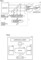
- Fig. 1 is a diagram illustrating a configuration of a system according to Embodiment 1, which includes the motor diagnostic device 7, the compressor 6, and an inverter 1.
- the motor diagnostic device 7 includes current detectors 3u, 3v, and 3w, a phase generator 100, a negative-sequence current detector 4, and a deterioration diagnoser 5.
- the current detector 3u is disposed on a U-phase line between the inverter 1 and a permanent magnet synchronous motor 2.
- the current detector 3v is disposed on a V-phase line between the inverter 1 and the permanent magnet synchronous motor 2.
- the current detector 3w is disposed on a W-phase line between the inverter 1 and the permanent magnet synchronous motor 2.
- the current detectors 3u, 3v, and 3w detect currents of the U-phase line, V-phase line, and W-phase line, respectively.
- the phase generator 100 outputs an opposite phase (opposite-phase information) - ⁇ e of a voltage phase ⁇ e of three-phase alternating voltages.
- the negative-sequence current detector 4 receives currents Iu, Iv, and Iw output from the current detectors 3u, 3v, and 3w, and the opposite-phase information - ⁇ e output from the phase generator 100. Based on the opposite-phase information - ⁇ e and the three-phase currents Iu, Iv, and Iw, the negative-sequence current detector 4 calculates a negative-sequence current I2.
- the deterioration diagnoser 5 diagnoses the deterioration of a plain bearing 9 supporting the permanent magnet synchronous motor 2.
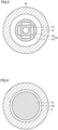
- Fig. 2 is a diagram showing a configuration of the compressor 6.
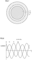
- Fig. 3 is a diagram illustrating a cross section of the permanent magnet synchronous motor 2 and a main shaft 10 when the plain bearing 9 is normal.
- Fig. 4 is a diagram illustrating a cross section of the plain bearing 9 and the main shaft 10 when the plain bearing 9 is normal.
- the compressor 6 includes a compressive element 8, the permanent magnet synchronous motor 2, the main shaft 10, the plain bearing 9, and a ball bearing 11.
- the permanent magnet synchronous motor 2 includes a stator 2a and a rotor 2b.
- the compressive element 8 compresses a gas load.
- the permanent magnet synchronous motor 2 rotates the compressive element 8, which is a load.
- the main shaft 10 is coupled to the rotor 2b and the compressive element 8.
- the ball bearing 11 and the plain bearing 9 support the centrifugal force and the gravity for allowing the rotational motion of the main shaft 10.
- the plain bearing 9 supports the permanent magnet synchronous motor 2.
- a hollow AG having a predetermined width is provided in a radial direction of the main shaft 10, between the plain bearing 9 and the main shaft 10.
- the hollow AG is, typically, lubricated with a lubricating oil.
- the stator 2a includes a winding and a stator core.
- the rotor 2b includes a permanent magnet 13 and a rotator core 14.
- the rotor 2b and the stator 2a are disposed coaxial with each other, having the gap 12 between the rotor 2b and the stator 2a.
- the gap 12 has a substantially uniform width.
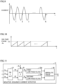
- Fig. 5 is a diagram illustrating waveforms of the motor current when the plain bearing 9 is normal.
- the permanent magnet synchronous motor 2 includes a winding that is designed to have a three-phase balanced impedance. Thus, as a three-phase balanced voltage is applied to the winding, balanced three-phase currents Iu, Iv, and Iw are obtained.
- Fig. 6 is a diagram illustrating a cross section of the permanent magnet synchronous motor 2 and the main shaft 10 when the plain bearing 9 is worn.
- Fig. 7 is a diagram illustrating a cross section of the plain bearing 9 and the main shaft 10 when the plain bearing 9 is worn.
- Fig. 8 is a diagram illustrating waveforms of the motor current when the plain bearing 9 is worn.
- the plain bearing 9 is worn due to various factors such as a lubrication failure or contamination.
- This enlarges the hollow AG greater than the initial design, as shown in Fig. 7 .
- the hollow AG also serves as a path for a refrigerant.
- the lubricant oil may be entrained by the refrigerant flow and flows out of the compressor 6.
- the compressor 6 is brought into a lubrication failure.
- the wear of the plain bearing 9 progresses.
- the main shaft 10 Since the plain bearing 9 supports the radial movement of the main shaft 10, the main shaft 10 is displaced as the hollow AG opens. Accordingly, the radial width of the gap 12 in the permanent magnet synchronous motor 2 is made non-uniform, causing the permanent magnet synchronous motor 2 to be decentered, as shown in Fig. 6 .
- the equilibrium of the impedances of the permanent magnet synchronous motor 2 comes undone due to the non-uniformity of the gap 12, resulting in the three phases being different in impedance.
- the three-phase currents Iu, Iv, and Iw include imbalance components, as shown in Fig. 8 .
- the imbalance current components are, generally, called negative-sequence currents.
- the negative-sequence currents are theoretically derived as components that rotate in the direction opposite the phase rotation direction of three-phase alternating currents.
- the phase generator 100 and the negative-sequence current detector 4 performs the following processes to extract imbalance components from the currents.
- the imbalance components of the currents are known to have a frequency equal to the frequency of the three-phase alternating currents, and a phase that rotates in the direction opposite the phase rotation direction of the three-phase alternating currents.
- the phase generator 100 detects a frequency f of the detected three-phase currents Iu, Iv, and Iw. Using the detected frequency f, the phase generator 100 generates a counter-rotating voltage phase - ⁇ e that rotates in the direction opposite the phase rotation direction of the three-phase alternating currents.
- Fig. 9 is a diagram for illustrating a method of detecting the frequency f of the three-phase currents Iu, Iv, and Iw by the phase generator 100.
- the phase generator 100 measures for a predetermined time period ⁇ T the number of times N the polarity of the current Iu is reversed in response to rising of the current Iu.
- Fig. 10 is a diagram for illustrating a method of generating the voltage phase ⁇ e from the frequency f.
- the phase generator 100 integrates the frequency f over time, thereby generating the voltage phase ⁇ e. Multiplying the voltage phase ⁇ e by -1 (reversing the sign) generates a counter-rotating voltage phase - ⁇ e, which is a voltage phase that rotates in a direction opposite the phase rotation direction of the multi-phase alternating currents.
- Fig. 11 is a diagram illustrating a configuration of the negative-sequence current detector 4 according to Embodiment 1.
- the negative-sequence current detector 4 includes a first phase transformer 31, a rotational coordinates transformer 32, a first low-pass filter 33a, a second low-pass filter 33b, and an absolute value operator 34.
- the first phase transformer 31 transforms the three-phase currents Iu, Iv, and Iw at a predetermined timing into two-phase currents I ⁇ and I ⁇ , based on Equation (2).
- I ⁇ I ⁇ 2 3 1 ⁇ 1 2 ⁇ 1 2 0 3 2 ⁇ 3 2 Iu Iv Iw
- the rotational coordinates transformer 32 transforms the two-phase currents I ⁇ and I ⁇ into a first-axis direct current component Id and a second-axis direct current component Iq, which are orthogonal to each other.
- Id Iq cos ⁇ ⁇ e ⁇ sin ⁇ ⁇ e sin ⁇ ⁇ e cos ⁇ ⁇ e I ⁇ I ⁇
- the first low-pass filter 33a receives the first-axis direct current component Id, and removes the alternating current component from the first-axis direct current component Id.
- the second low-pass filter 33b receives the second-axis direct current component Iq, and removes the alternating current component from the second-axis direct current component Iq.
- the absolute value operator 34 calculates a square root of the sum of a square of the output of the first low-pass filter 33a and a square of the output of the second low-pass filter 33b, as the negative-sequence current I2.
- the rotational coordinates transformer 32, the first low-pass filter 33a, and the second low-pass filter 33b form a band-pass filter specific to the current component that rotates the permanent magnet synchronous motor 2 in the opposite direction.
- the deterioration diagnoser 5 Based on the negative-sequence current I2, the deterioration diagnoser 5 detects enlargement of the hollow AG between the main shaft 10 and the plain bearing 9 supporting the permanent magnet synchronous motor 2. More specifically, the deterioration diagnoser 5 estimates an amount of wear AT of the plain bearing 9, based on a mathematical formula between the previously determined negative-sequence current I2 and the amount of wear AT of the plain bearing. The amount of wear AT represents enlargement of the hollow AG.
- the deterioration diagnoser 5 may estimate the amount of eccentricity EC of the permanent magnet synchronous motor 2, based on a mathematical formula between the previously determined negative-sequence current I2 and the amount of eccentricity EC of the permanent magnet synchronous motor.
- the amount of eccentricity EC of the permanent magnet synchronous motor 2 represents the enlargement of the hollow AG.
- the amount of eccentricity EC of the permanent magnet synchronous motor 2 allows estimation of the amount of wear AT of the plain bearing 9.
- the plain bearing 9 can be diagnosed as being abnormal.
- the number of slots of the stator 2a is an integer multiple of 3. If the stator 2a has odd numbers of slots, the phase having a reduced gap with the rotor 2b and the phase having an enlarged gap with the rotor 2b, caused by the eccentricity, are always different phases. Therefore, the changes in the negative-sequence current I2 increases, as compared to Embodiment 1, allowing more accurate diagnosis.
- Fig. 12 is a schematic cross-sectional diagram of the 9-slot motor.
- Fig. 12 shows only three slots of the 9-slot motor.
- a slot 20, a stator core 21, and a teeth portion 21a of the stator core are shown.
- the 9-slot motor includes nine teeth portions 21a, and any of a U winding, a V winding, and a W winding is wound around each teeth portion 21a.
- the motor diagnostic device extracts an imbalance component from the motor current to estimate the amount of eccentricity of the permanent magnet synchronous motor 2 or the amount of wear of the plain bearing 9.
- This allows the wear of the plain bearing to be detected, without disassembling the plain bearing 9 and newly providing a vibration sensor.
- Using clamp-type sensors as the current detectors 3u, 3v, and 3w obviates the need for disconnecting the wiring of the device to be measured, thereby more simplifying the inspection.
- the diagnosis of the wear of the plain bearing is highly needed for compressors, etc. the oiling and maintenance for which is difficult. Thus, the diagnosis of the wear of the plain bearing can be highly exploited and applicable.
- Fig. 13 is a diagram illustrating a configuration of a system according to Embodiment 2, which includes an inverter 1A and a compressor 6.
- the inverter 1A has a motor diagnostic device 7A and current detectors 3u, 3v, and 3w incorporated therein.
- a phase generator 100A within the motor diagnostic device 7A reverses and outputs a voltage phase ⁇ e, which is an internal signal of the inverter 1A.
- the voltage phase ⁇ e is used by the inverter 1A to generate three-phase alternating voltages Vu, Vv, and Vw.
- the inverter 1A thus configured requires no detection of a frequency f of the three-phase currents as described in Embodiment 1. As a result, the processing by the phase generator 100A is simplified and excellent conformability to the diagnosis is also achieved upon changes in frequency.
- the inverter 1 since the inverter 1 has the current detectors 3u, 3v, and 3w, there is no need to additionally add the current detectors 3u, 3v, and 3w. Thus, the motor can be diagnosed inexpensively.
- the inverter 1A can recognize the wear of the plain bearing 9 of the compressor 6, independent of the compressor 6, the inverter 1A can monitor the compressor 6 at all times. This can extend the life of the plain bearing 9 in real time by, for example, reducing the frequency f of the three-phase currents.
- Fig. 14 is a diagram illustrating a configuration of a system according to Embodiment 3, which includes an inverter 1B, a compressor 6, and a ground fault interrupter 29.
- the system according to Embodiment 3 differs from the system according to Embodiment 2 in that: the inverter 1B according to Embodiment 3 does not include the V-phase current detector 3v, and that the ground fault interrupter 29 is disposed between the inverter 1B and a system power supply 22.
- the ground fault interrupter 29 disconnects the system power supply 22 and the inverter 1B from each other.
- a negative-sequence current detector disregarding the zero-phase current, can be configured.
- Fig. 15 is a diagram illustrating a configuration of the negative-sequence current detector 4A according to Embodiment 3.
- the negative-sequence current detector 4A according to Embodiment 3 differs from the negative-sequence current detector 4 according to Embodiment 1 of Fig. 2 in that the negative-sequence current detector 4A further includes a phase transformer 35.
- the phase transformer 35 calculates Iv not yet detected, based on the following equation. In other words, the phase transformer 35 calculates the sum of Iu and Iv, and reverses the sign of the sum, thereby calculating Iv.
- the number of current detectors are reduced from three to two, assuming a system that can disregard the leak current.
- the motor can be diagnosed inexpensively.
- the motor diagnostic device detects the wear of a bearing
- the motor diagnostic device can be used for a motor that includes a magnetic bearing which may be constantly decentralized.
Landscapes
- Engineering & Computer Science (AREA)
- Power Engineering (AREA)
- Physics & Mathematics (AREA)
- General Physics & Mathematics (AREA)
- Control Of Ac Motors In General (AREA)
- Tests Of Circuit Breakers, Generators, And Electric Motors (AREA)
- Control Of Electric Motors In General (AREA)
Claims (8)
- Dispositif de diagnostic (7, 7A, 7B) de moteur synchrone à aimants permanents, comprenant :un calculateur de courant à séquence négative (5) configuré pour calculer un courant à séquence négative, sur la base de grandeurs d'une pluralité de courants de phase circulant à travers un moteur synchrone à aimants permanents (2) qui fait tourner une charge (8) ;un dispositif de diagnostic de détérioration (6) configuré pour diagnostiquer, sur la base du courant à séquence négative, une détérioration d'un palier lisse (9) soutenant un arbre principal (10) couplé au moteur synchrone à aimants permanents (2) ; etun générateur de phase (100) configuré pour détecter une fréquence de la pluralité de courants de phase et pour générer, en utilisant la fréquence, une phase de tension de contre-rotation, qui tourne dans une direction opposée à une direction de rotation de phase de la pluralité de courants alternatifs de phase,le calculateur de courant à séquence négative (5) étant configuré pour calculer le courant à séquence négative, sur la base de la phase de tension de contre-rotation et de la pluralité de courants de phase.
- Dispositif de diagnostic (7) de moteur synchrone à aimants permanents selon la revendication 1, le dispositif de diagnostic de détérioration (6) étant configuré pour détecter un élargissement d'un vide entre le palier lisse (9) et l'arbre principal (10), sur la base du courant à séquence négative.
- Dispositif de diagnostic (7) de moteur synchrone à aimants permanents selon la revendication 2,
le dispositif de diagnostic de détérioration (6) étant configuré pour estimer un niveau d'usure du palier lisse (9), sur la base du courant à séquence négative. - Dispositif de diagnostic (7) de moteur synchrone à aimants permanents selon la revendication 2,
le dispositif de diagnostic de détérioration (6) étant configuré pour estimer un niveau d'excentricité du moteur synchrone à aimants permanents (2), sur la base du courant à séquence négative. - Dispositif de diagnostic (7) de moteur synchrone à aimants permanents selon la revendication 1,la pluralité de courants de phase étant des courants triphasés,le calculateur de courant à séquence négative (5) comportant :un transformateur de phase (31) configuré pour transformer les grandeurs des courants triphasés en grandeurs de courants à deux phases ;un transformateur de coordonnées de rotation (32) configuré pour transformer la grandeur des courants à deux phases en une composante de courant continu de premier axe et une composante de courant continu de deuxième axe, qui sont orthogonales l'une à l'autre ;un premier filtre passe-bas (33a) recevant la composante de courant continu de premier axe ;un deuxième filtre passe-bas (33b) recevant la composante de courant continu de deuxième axe ; etun opérateur (34) configuré pour calculer une racine carrée d'une somme d'un carré d'une sortie du premier filtre passe-bas (33a) et un carré d'une sortie du deuxième filtre passe-bas (33b), en tant que courant à séquence négative.
- Dispositif de diagnostic (7) de moteur synchrone à aimants permanents selon la revendication 5, comprenant
trois détecteurs de courant (3u, 3v, 3w), chaque détecteur de courant desquels détectant une grandeur d'un courant de phase correspondant parmi les courants triphasés. - Dispositif de diagnostic (7B) de moteur synchrone à aimants permanents selon la revendication 1,un interrupteur de défaut de masse (29) étant disposé entre une alimentation électrique de système (22) et un onduleur (1B) qui entraîne le moteur synchrone à aimants permanents (2), l'interrupteur de défaut de masse (29) déconnectant l'alimentation électrique de système (22) et l'onduleur (1B) l'un de l'autre lorsqu'un courant à déphasage nul ayant une valeur prédéterminée ou plus circule entre l'alimentation électrique de système (22) et l'onduleur (1B),la pluralité de courants de phase étant des courants triphasés, le dispositif de diagnostic (7B) de moteur synchrone à aimants permanents comprenant :un premier détecteur de courant (3u) détectant une grandeur d'un courant de première phase parmi les courants triphasés ; etun deuxième détecteur de courant (3w) détectant une grandeur d'un courant de deuxième phase parmi les courants triphasés,le calculateur de courant à séquence négative (5) comportant :un premier transformateur de phase (35) qui est configuré pour calculer une somme de la grandeur du courant de première phase et la grandeur du courant de deuxième phase, pour calculer une grandeur d'un courant de troisième phase, parmi les courants triphasés, en inversant un signe d'une valeur de la somme, et qui délivre les grandeurs des courants triphasés consistant en le courant de première phase, le courant de deuxième phase et le courant de troisième phase ;un deuxième transformateur de phase (31) configuré pour transformer les grandeurs des courants triphasés en grandeurs de courants à deux phases ;un transformateur de coordonnées de rotation (32) configuré pour transformer les grandeurs des courants à deux phases en une composante de courant continu de premier axe et une composante de courant continu de deuxième axe, qui sont orthogonales l'une à l'autre ;un premier filtre passe-bas (33a) recevant la composante de courant continu de premier axe ;un deuxième filtre passe-bas (33b) recevant la composante de courant continu de deuxième axe ; etun opérateur (34) configuré pour calculer une racine carrée d'une somme d'un carré d'une sortie du premier filtre passe-bas (33a) et un carré d'une sortie du deuxième filtre passe-bas (33b), en tant que courant à séquence négative.
- Onduleur (1A), comprenant :le dispositif de diagnostic (7A) de moteur synchrone à aimants permanents selon la revendication 1, etun générateur de commande de tension (110) configuré pour générer, sur la base d'une phase de tension, une pluralité de valeurs de commande de tension de phase pour entraîner le moteur synchrone à aimants permanents (2),le dispositif de diagnostic (7A) de moteur synchrone à aimants permanents, comportant en outre :un générateur de phase (100) configuré pour générer une phase de tension de contre-rotation qui tourne dans une direction opposée à une direction de rotation de phase de la pluralité de courants alternatifs de phase en inversant un signe de la phase de tension,le calculateur de courant à séquence négative (5) étant configuré pour calculer le courant à séquence négative, sur la base d'une grandeur de la phase de tension de contre-rotation et de grandeurs de la pluralité de courants de phase.
Applications Claiming Priority (1)
| Application Number | Priority Date | Filing Date | Title |
|---|---|---|---|
| PCT/JP2020/006102 WO2021166042A1 (fr) | 2020-02-17 | 2020-02-17 | Dispositif de diagnostic d'un moteur synchrone à aimant permanent, et onduleur comprenant ledit dispositif de diagnostic |
Publications (3)
| Publication Number | Publication Date |
|---|---|
| EP4109721A1 EP4109721A1 (fr) | 2022-12-28 |
| EP4109721A4 EP4109721A4 (fr) | 2023-04-12 |
| EP4109721B1 true EP4109721B1 (fr) | 2024-01-31 |
Family
ID=77390641
Family Applications (1)
| Application Number | Title | Priority Date | Filing Date |
|---|---|---|---|
| EP20919728.4A Active EP4109721B1 (fr) | 2020-02-17 | 2020-02-17 | Dispositif de diagnostic d'un moteur synchrone à aimant permanent, et onduleur comprenant ledit dispositif de diagnostic |
Country Status (5)
| Country | Link |
|---|---|
| US (1) | US12032025B2 (fr) |
| EP (1) | EP4109721B1 (fr) |
| JP (1) | JP7379652B2 (fr) |
| CN (1) | CN115066826B (fr) |
| WO (1) | WO2021166042A1 (fr) |
Families Citing this family (5)
| Publication number | Priority date | Publication date | Assignee | Title |
|---|---|---|---|---|
| DE102022119945B3 (de) | 2022-08-08 | 2024-01-25 | Danfoss Power Electronics A/S | Verfahren zum Detektieren eines Kurzschlusses und Steuereinheit |
| US20240126251A1 (en) * | 2022-10-13 | 2024-04-18 | Bingnan Wang | System And Method For Motor Eccentricity Level Prediction Using Topological Data Analysis |
| KR102558372B1 (ko) * | 2023-02-03 | 2023-07-24 | 멜콘 주식회사 | 인버터로 구동되는 모터의 베어링 전류를 검출하는 방법 |
| CN116105411B (zh) * | 2023-04-04 | 2023-07-18 | 宁波奥克斯电气股份有限公司 | 压缩机控制方法、装置、空调器及存储介质 |
| JPWO2024247114A1 (fr) * | 2023-05-30 | 2024-12-05 |
Family Cites Families (25)
| Publication number | Priority date | Publication date | Assignee | Title |
|---|---|---|---|---|
| JPH01172621A (ja) | 1987-12-26 | 1989-07-07 | Tosoh Corp | 転がり軸受けの異常検出方法 |
| US5270640A (en) * | 1992-04-23 | 1993-12-14 | The Penn State Research Foundation | Method for incipient failure detection in electric machines |
| JP3671367B2 (ja) | 2000-12-20 | 2005-07-13 | エイテック株式会社 | 電気機器設備の異常診断方法 |
| JP3561882B2 (ja) | 2001-09-03 | 2004-09-02 | エイテック株式会社 | 電気機器の劣化診断法 |
| US7570074B2 (en) * | 2005-05-09 | 2009-08-04 | Square D Company | Electronic overload relay for mains-fed induction motors |
| JP4299271B2 (ja) | 2005-06-14 | 2009-07-22 | トライボテックス株式会社 | 滑り軸受け装着機械の保守方法 |
| EP2221597A1 (fr) * | 2007-11-14 | 2010-08-25 | Universitat Politècnica de Catalunya | Système pour le diagnostic de pannes dans des moteurs électriques |
| JP4732468B2 (ja) | 2008-01-21 | 2011-07-27 | 株式会社リコー | 軸受異常検出装置、画像形成装置及びディスクドライブ装置 |
| US8135551B2 (en) * | 2009-02-03 | 2012-03-13 | General Electric Company | Robust on line stator turn fault identification system |
| JP4782218B2 (ja) * | 2009-06-10 | 2011-09-28 | 新日本製鐵株式会社 | 設備の異常診断方法 |
| US8401822B2 (en) * | 2010-04-20 | 2013-03-19 | Eaton Corporation | System, wellness circuit and method of determining wellness of a rotating electrical apparatus |
| US8803461B2 (en) * | 2010-12-22 | 2014-08-12 | Arvind Kumar Tiwari | System and method for synchronous machine health monitoring |
| JP2013160749A (ja) | 2012-02-09 | 2013-08-19 | Shinshu Univ | 回転機械の設備診断方法及び設備診断装置 |
| KR101852246B1 (ko) | 2013-03-29 | 2018-04-25 | 미쓰비시덴키 가부시키가이샤 | 전동기의 진단 장치 및 개폐 장치 |
| GB2534406B (en) * | 2015-01-23 | 2017-01-11 | Rolls Royce Plc | Fault detection and diagnosis |
| JP6271452B2 (ja) * | 2015-02-06 | 2018-01-31 | 東芝三菱電機産業システム株式会社 | 回転電機システム |
| CN108702075A (zh) * | 2016-01-20 | 2018-10-23 | 三菱电机株式会社 | 永久磁铁同步电动机、压缩机及空气调节机 |
| US10273940B2 (en) * | 2016-05-12 | 2019-04-30 | General Electric Company | System and method for detecting pitch bearing damage in a wind turbine |
| US11221377B2 (en) * | 2016-12-15 | 2022-01-11 | Eaton Intelligent Power Limited | System and method for detecting stator faults in AC electrical machines |
| CN106483461B (zh) * | 2017-01-05 | 2019-06-11 | 深圳市双合电气股份有限公司 | 电机节能分析及故障状态监测系统 |
| KR101905478B1 (ko) * | 2017-02-02 | 2018-10-08 | 엘지전자 주식회사 | 압축기 구동장치 및 이를 구비한 칠러 |
| WO2019003389A1 (fr) * | 2017-06-29 | 2019-01-03 | 三菱電機株式会社 | Dispositif de diagnostic de moteur électrique |
| CN111344946A (zh) * | 2017-11-22 | 2020-06-26 | 三菱电机株式会社 | 设备劣化诊断装置 |
| KR101960632B1 (ko) * | 2018-02-06 | 2019-03-20 | 엘지전자 주식회사 | 모터의 편심에 의한 출력 저하를 보상하는 압축기 구동 장치 |
| JP7109656B2 (ja) * | 2019-04-10 | 2022-07-29 | 三菱電機株式会社 | 電動機設備の異常診断装置、電動機設備の異常診断方法、および電動機設備の異常診断システム |
-
2020
- 2020-02-17 EP EP20919728.4A patent/EP4109721B1/fr active Active
- 2020-02-17 US US17/781,367 patent/US12032025B2/en active Active
- 2020-02-17 JP JP2022501414A patent/JP7379652B2/ja active Active
- 2020-02-17 WO PCT/JP2020/006102 patent/WO2021166042A1/fr not_active Ceased
- 2020-02-17 CN CN202080096077.7A patent/CN115066826B/zh active Active
Also Published As
| Publication number | Publication date |
|---|---|
| EP4109721A4 (fr) | 2023-04-12 |
| JPWO2021166042A1 (fr) | 2021-08-26 |
| WO2021166042A1 (fr) | 2021-08-26 |
| EP4109721A1 (fr) | 2022-12-28 |
| CN115066826B (zh) | 2025-02-25 |
| US12032025B2 (en) | 2024-07-09 |
| JP7379652B2 (ja) | 2023-11-14 |
| CN115066826A (zh) | 2022-09-16 |
| US20230003798A1 (en) | 2023-01-05 |
Similar Documents
| Publication | Publication Date | Title |
|---|---|---|
| EP4109721B1 (fr) | Dispositif de diagnostic d'un moteur synchrone à aimant permanent, et onduleur comprenant ledit dispositif de diagnostic | |
| Eltabach et al. | A comparison of external and internal methods of signal spectral analysis for broken rotor bars detection in induction motors | |
| Riley et al. | Stator current harmonics and their causal vibrations: A preliminary investigation of sensorless vibration monitoring applications | |
| Mehala et al. | Motor current signature analysis and its applications in induction motor fault diagnosis | |
| Kliman et al. | Methods of motor current signature analysis | |
| Trzynadlowski et al. | Diagnostics of mechanical abnormalities in induction motors using instantaneous electric power | |
| Immovilli et al. | Diagnosis of bearing faults in induction machines by vibration or current signals: A critical comparison | |
| Alwodai et al. | A comparison of different techniques for induction motor rotor fault diagnosis | |
| EP2919027A1 (fr) | Détection de défaillances dans des machines à induction | |
| EP3480610B1 (fr) | Diagnostic d'un ensemble d'enroulement d'un stator | |
| Thomas et al. | Online cage rotor fault detection using air-gap torque spectra | |
| EP2733497A1 (fr) | Procédé permettant d'estimer la fréquence d'une harmonique dans un courant alternatif passant vers/à partir d'une machine à courant alternatif | |
| Khelfi et al. | Stator current demodulation using Hilbert transform for inverter-fed induction motor at low load conditions | |
| US20210028731A1 (en) | Monitoring a multi-winding set stator | |
| Kral et al. | Model-based detection of rotor faults without rotor position sensor-the sensorless Vienna monitoring method | |
| Bhardwaj et al. | Fault diagnosis of three phase induction motor using fuzzy logic controller and sequence analyzer | |
| KR20120087088A (ko) | 모터의 상황 검사 방법 및 모터 특성 검사 장치 | |
| EP4199346A1 (fr) | Diagnostic de défaillance d'enroulement de moteur | |
| Kumar et al. | LabVIEW based condition monitoring of induction machines | |
| Arkan | Sensorless speed estimation in induction motor drives by using the space vector angular fluctuation signal | |
| Reljić et al. | Application of the Goertzel’s algorithm in the airgap mixed eccentricity fault detection | |
| Drif et al. | Airgap eccentricity fault diagnosis, in three-phase induction motors, by the instantaneous power signature analysis | |
| US20240162790A1 (en) | Magnetic gap length estimating device, magnetic gap length estimating method, and driving device for rotating electric machine | |
| Meira et al. | A speed self-sensing method in starting of induction motors | |
| Thomas et al. | Implementation of online air-gap torque monitor for detection of squirrel cage rotor faults using TMS320C31 |
Legal Events
| Date | Code | Title | Description |
|---|---|---|---|
| STAA | Information on the status of an ep patent application or granted ep patent |
Free format text: STATUS: THE INTERNATIONAL PUBLICATION HAS BEEN MADE |
|
| PUAI | Public reference made under article 153(3) epc to a published international application that has entered the european phase |
Free format text: ORIGINAL CODE: 0009012 |
|
| STAA | Information on the status of an ep patent application or granted ep patent |
Free format text: STATUS: REQUEST FOR EXAMINATION WAS MADE |
|
| 17P | Request for examination filed |
Effective date: 20220725 |
|
| AK | Designated contracting states |
Kind code of ref document: A1 Designated state(s): AL AT BE BG CH CY CZ DE DK EE ES FI FR GB GR HR HU IE IS IT LI LT LU LV MC MK MT NL NO PL PT RO RS SE SI SK SM TR |
|
| REG | Reference to a national code |
Ref country code: DE Free format text: PREVIOUS MAIN CLASS: H02K0011000000 Ref country code: DE Ref legal event code: R079 Ref document number: 602020025216 Country of ref document: DE Free format text: PREVIOUS MAIN CLASS: H02K0011000000 Ipc: G01R0031340000 |
|
| A4 | Supplementary search report drawn up and despatched |
Effective date: 20230309 |
|
| RIC1 | Information provided on ipc code assigned before grant |
Ipc: H02P 29/024 20160101ALI20230303BHEP Ipc: H02P 25/022 20160101ALI20230303BHEP Ipc: H02P 25/00 20060101ALI20230303BHEP Ipc: H02P 4/00 20060101ALI20230303BHEP Ipc: H02K 11/00 20060101ALI20230303BHEP Ipc: G01R 31/34 20060101AFI20230303BHEP |
|
| DAV | Request for validation of the european patent (deleted) | ||
| DAX | Request for extension of the european patent (deleted) | ||
| GRAP | Despatch of communication of intention to grant a patent |
Free format text: ORIGINAL CODE: EPIDOSNIGR1 |
|
| STAA | Information on the status of an ep patent application or granted ep patent |
Free format text: STATUS: GRANT OF PATENT IS INTENDED |
|
| RIC1 | Information provided on ipc code assigned before grant |
Ipc: H02P 29/024 20160101ALI20230731BHEP Ipc: H02P 25/022 20160101ALI20230731BHEP Ipc: H02P 25/00 20060101ALI20230731BHEP Ipc: H02P 4/00 20060101ALI20230731BHEP Ipc: H02K 11/00 20160101ALI20230731BHEP Ipc: G01R 31/34 20200101AFI20230731BHEP |
|
| INTG | Intention to grant announced |
Effective date: 20230828 |
|
| P01 | Opt-out of the competence of the unified patent court (upc) registered |
Effective date: 20231107 |
|
| GRAS | Grant fee paid |
Free format text: ORIGINAL CODE: EPIDOSNIGR3 |
|
| GRAA | (expected) grant |
Free format text: ORIGINAL CODE: 0009210 |
|
| STAA | Information on the status of an ep patent application or granted ep patent |
Free format text: STATUS: THE PATENT HAS BEEN GRANTED |
|
| AK | Designated contracting states |
Kind code of ref document: B1 Designated state(s): AL AT BE BG CH CY CZ DE DK EE ES FI FR GB GR HR HU IE IS IT LI LT LU LV MC MK MT NL NO PL PT RO RS SE SI SK SM TR |
|
| REG | Reference to a national code |
Ref country code: GB Ref legal event code: FG4D Ref country code: CH Ref legal event code: EP |
|
| REG | Reference to a national code |
Ref country code: DE Ref legal event code: R096 Ref document number: 602020025216 Country of ref document: DE |
|
| REG | Reference to a national code |
Ref country code: IE Ref legal event code: FG4D |
|
| REG | Reference to a national code |
Ref country code: LT Ref legal event code: MG9D |
|
| REG | Reference to a national code |
Ref country code: NL Ref legal event code: MP Effective date: 20240131 |
|
| PG25 | Lapsed in a contracting state [announced via postgrant information from national office to epo] |
Ref country code: IS Free format text: LAPSE BECAUSE OF FAILURE TO SUBMIT A TRANSLATION OF THE DESCRIPTION OR TO PAY THE FEE WITHIN THE PRESCRIBED TIME-LIMIT Effective date: 20240531 |
|
| PG25 | Lapsed in a contracting state [announced via postgrant information from national office to epo] |
Ref country code: LT Free format text: LAPSE BECAUSE OF FAILURE TO SUBMIT A TRANSLATION OF THE DESCRIPTION OR TO PAY THE FEE WITHIN THE PRESCRIBED TIME-LIMIT Effective date: 20240131 |
|
| PG25 | Lapsed in a contracting state [announced via postgrant information from national office to epo] |
Ref country code: GR Free format text: LAPSE BECAUSE OF FAILURE TO SUBMIT A TRANSLATION OF THE DESCRIPTION OR TO PAY THE FEE WITHIN THE PRESCRIBED TIME-LIMIT Effective date: 20240501 |
|
| REG | Reference to a national code |
Ref country code: AT Ref legal event code: MK05 Ref document number: 1654224 Country of ref document: AT Kind code of ref document: T Effective date: 20240131 |
|
| PG25 | Lapsed in a contracting state [announced via postgrant information from national office to epo] |
Ref country code: RS Free format text: LAPSE BECAUSE OF FAILURE TO SUBMIT A TRANSLATION OF THE DESCRIPTION OR TO PAY THE FEE WITHIN THE PRESCRIBED TIME-LIMIT Effective date: 20240430 Ref country code: NL Free format text: LAPSE BECAUSE OF FAILURE TO SUBMIT A TRANSLATION OF THE DESCRIPTION OR TO PAY THE FEE WITHIN THE PRESCRIBED TIME-LIMIT Effective date: 20240131 Ref country code: HR Free format text: LAPSE BECAUSE OF FAILURE TO SUBMIT A TRANSLATION OF THE DESCRIPTION OR TO PAY THE FEE WITHIN THE PRESCRIBED TIME-LIMIT Effective date: 20240131 |
|
| PG25 | Lapsed in a contracting state [announced via postgrant information from national office to epo] |
Ref country code: ES Free format text: LAPSE BECAUSE OF FAILURE TO SUBMIT A TRANSLATION OF THE DESCRIPTION OR TO PAY THE FEE WITHIN THE PRESCRIBED TIME-LIMIT Effective date: 20240131 |
|
| PG25 | Lapsed in a contracting state [announced via postgrant information from national office to epo] |
Ref country code: AT Free format text: LAPSE BECAUSE OF FAILURE TO SUBMIT A TRANSLATION OF THE DESCRIPTION OR TO PAY THE FEE WITHIN THE PRESCRIBED TIME-LIMIT Effective date: 20240131 |
|
| PG25 | Lapsed in a contracting state [announced via postgrant information from national office to epo] |
Ref country code: RS Free format text: LAPSE BECAUSE OF FAILURE TO SUBMIT A TRANSLATION OF THE DESCRIPTION OR TO PAY THE FEE WITHIN THE PRESCRIBED TIME-LIMIT Effective date: 20240430 Ref country code: NO Free format text: LAPSE BECAUSE OF FAILURE TO SUBMIT A TRANSLATION OF THE DESCRIPTION OR TO PAY THE FEE WITHIN THE PRESCRIBED TIME-LIMIT Effective date: 20240430 Ref country code: NL Free format text: LAPSE BECAUSE OF FAILURE TO SUBMIT A TRANSLATION OF THE DESCRIPTION OR TO PAY THE FEE WITHIN THE PRESCRIBED TIME-LIMIT Effective date: 20240131 Ref country code: LT Free format text: LAPSE BECAUSE OF FAILURE TO SUBMIT A TRANSLATION OF THE DESCRIPTION OR TO PAY THE FEE WITHIN THE PRESCRIBED TIME-LIMIT Effective date: 20240131 Ref country code: IS Free format text: LAPSE BECAUSE OF FAILURE TO SUBMIT A TRANSLATION OF THE DESCRIPTION OR TO PAY THE FEE WITHIN THE PRESCRIBED TIME-LIMIT Effective date: 20240531 Ref country code: HR Free format text: LAPSE BECAUSE OF FAILURE TO SUBMIT A TRANSLATION OF THE DESCRIPTION OR TO PAY THE FEE WITHIN THE PRESCRIBED TIME-LIMIT Effective date: 20240131 Ref country code: GR Free format text: LAPSE BECAUSE OF FAILURE TO SUBMIT A TRANSLATION OF THE DESCRIPTION OR TO PAY THE FEE WITHIN THE PRESCRIBED TIME-LIMIT Effective date: 20240501 Ref country code: FI Free format text: LAPSE BECAUSE OF FAILURE TO SUBMIT A TRANSLATION OF THE DESCRIPTION OR TO PAY THE FEE WITHIN THE PRESCRIBED TIME-LIMIT Effective date: 20240131 Ref country code: ES Free format text: LAPSE BECAUSE OF FAILURE TO SUBMIT A TRANSLATION OF THE DESCRIPTION OR TO PAY THE FEE WITHIN THE PRESCRIBED TIME-LIMIT Effective date: 20240131 Ref country code: BG Free format text: LAPSE BECAUSE OF FAILURE TO SUBMIT A TRANSLATION OF THE DESCRIPTION OR TO PAY THE FEE WITHIN THE PRESCRIBED TIME-LIMIT Effective date: 20240131 Ref country code: AT Free format text: LAPSE BECAUSE OF FAILURE TO SUBMIT A TRANSLATION OF THE DESCRIPTION OR TO PAY THE FEE WITHIN THE PRESCRIBED TIME-LIMIT Effective date: 20240131 |
|
| PG25 | Lapsed in a contracting state [announced via postgrant information from national office to epo] |
Ref country code: PT Free format text: LAPSE BECAUSE OF FAILURE TO SUBMIT A TRANSLATION OF THE DESCRIPTION OR TO PAY THE FEE WITHIN THE PRESCRIBED TIME-LIMIT Effective date: 20240531 Ref country code: PL Free format text: LAPSE BECAUSE OF FAILURE TO SUBMIT A TRANSLATION OF THE DESCRIPTION OR TO PAY THE FEE WITHIN THE PRESCRIBED TIME-LIMIT Effective date: 20240131 |
|
| PG25 | Lapsed in a contracting state [announced via postgrant information from national office to epo] |
Ref country code: SE Free format text: LAPSE BECAUSE OF FAILURE TO SUBMIT A TRANSLATION OF THE DESCRIPTION OR TO PAY THE FEE WITHIN THE PRESCRIBED TIME-LIMIT Effective date: 20240131 Ref country code: PT Free format text: LAPSE BECAUSE OF FAILURE TO SUBMIT A TRANSLATION OF THE DESCRIPTION OR TO PAY THE FEE WITHIN THE PRESCRIBED TIME-LIMIT Effective date: 20240531 Ref country code: PL Free format text: LAPSE BECAUSE OF FAILURE TO SUBMIT A TRANSLATION OF THE DESCRIPTION OR TO PAY THE FEE WITHIN THE PRESCRIBED TIME-LIMIT Effective date: 20240131 Ref country code: LV Free format text: LAPSE BECAUSE OF FAILURE TO SUBMIT A TRANSLATION OF THE DESCRIPTION OR TO PAY THE FEE WITHIN THE PRESCRIBED TIME-LIMIT Effective date: 20240131 |
|
| REG | Reference to a national code |
Ref country code: CH Ref legal event code: PL |
|
| PG25 | Lapsed in a contracting state [announced via postgrant information from national office to epo] |
Ref country code: DK Free format text: LAPSE BECAUSE OF FAILURE TO SUBMIT A TRANSLATION OF THE DESCRIPTION OR TO PAY THE FEE WITHIN THE PRESCRIBED TIME-LIMIT Effective date: 20240131 |
|
| PG25 | Lapsed in a contracting state [announced via postgrant information from national office to epo] |
Ref country code: SM Free format text: LAPSE BECAUSE OF FAILURE TO SUBMIT A TRANSLATION OF THE DESCRIPTION OR TO PAY THE FEE WITHIN THE PRESCRIBED TIME-LIMIT Effective date: 20240131 |
|
| PG25 | Lapsed in a contracting state [announced via postgrant information from national office to epo] |
Ref country code: LU Free format text: LAPSE BECAUSE OF NON-PAYMENT OF DUE FEES Effective date: 20240217 |
|
| PG25 | Lapsed in a contracting state [announced via postgrant information from national office to epo] |
Ref country code: CH Free format text: LAPSE BECAUSE OF NON-PAYMENT OF DUE FEES Effective date: 20240229 |
|
| PG25 | Lapsed in a contracting state [announced via postgrant information from national office to epo] |
Ref country code: EE Free format text: LAPSE BECAUSE OF FAILURE TO SUBMIT A TRANSLATION OF THE DESCRIPTION OR TO PAY THE FEE WITHIN THE PRESCRIBED TIME-LIMIT Effective date: 20240131 Ref country code: CZ Free format text: LAPSE BECAUSE OF FAILURE TO SUBMIT A TRANSLATION OF THE DESCRIPTION OR TO PAY THE FEE WITHIN THE PRESCRIBED TIME-LIMIT Effective date: 20240131 |
|
| PG25 | Lapsed in a contracting state [announced via postgrant information from national office to epo] |
Ref country code: SK Free format text: LAPSE BECAUSE OF FAILURE TO SUBMIT A TRANSLATION OF THE DESCRIPTION OR TO PAY THE FEE WITHIN THE PRESCRIBED TIME-LIMIT Effective date: 20240131 |
|
| PG25 | Lapsed in a contracting state [announced via postgrant information from national office to epo] |
Ref country code: SM Free format text: LAPSE BECAUSE OF FAILURE TO SUBMIT A TRANSLATION OF THE DESCRIPTION OR TO PAY THE FEE WITHIN THE PRESCRIBED TIME-LIMIT Effective date: 20240131 Ref country code: SK Free format text: LAPSE BECAUSE OF FAILURE TO SUBMIT A TRANSLATION OF THE DESCRIPTION OR TO PAY THE FEE WITHIN THE PRESCRIBED TIME-LIMIT Effective date: 20240131 Ref country code: RO Free format text: LAPSE BECAUSE OF FAILURE TO SUBMIT A TRANSLATION OF THE DESCRIPTION OR TO PAY THE FEE WITHIN THE PRESCRIBED TIME-LIMIT Effective date: 20240131 Ref country code: LU Free format text: LAPSE BECAUSE OF NON-PAYMENT OF DUE FEES Effective date: 20240217 Ref country code: EE Free format text: LAPSE BECAUSE OF FAILURE TO SUBMIT A TRANSLATION OF THE DESCRIPTION OR TO PAY THE FEE WITHIN THE PRESCRIBED TIME-LIMIT Effective date: 20240131 Ref country code: DK Free format text: LAPSE BECAUSE OF FAILURE TO SUBMIT A TRANSLATION OF THE DESCRIPTION OR TO PAY THE FEE WITHIN THE PRESCRIBED TIME-LIMIT Effective date: 20240131 Ref country code: CZ Free format text: LAPSE BECAUSE OF FAILURE TO SUBMIT A TRANSLATION OF THE DESCRIPTION OR TO PAY THE FEE WITHIN THE PRESCRIBED TIME-LIMIT Effective date: 20240131 Ref country code: CH Free format text: LAPSE BECAUSE OF NON-PAYMENT OF DUE FEES Effective date: 20240229 |
|
| REG | Reference to a national code |
Ref country code: DE Ref legal event code: R097 Ref document number: 602020025216 Country of ref document: DE |
|
| PG25 | Lapsed in a contracting state [announced via postgrant information from national office to epo] |
Ref country code: MC Free format text: LAPSE BECAUSE OF FAILURE TO SUBMIT A TRANSLATION OF THE DESCRIPTION OR TO PAY THE FEE WITHIN THE PRESCRIBED TIME-LIMIT Effective date: 20240131 |
|
| PG25 | Lapsed in a contracting state [announced via postgrant information from national office to epo] |
Ref country code: MC Free format text: LAPSE BECAUSE OF FAILURE TO SUBMIT A TRANSLATION OF THE DESCRIPTION OR TO PAY THE FEE WITHIN THE PRESCRIBED TIME-LIMIT Effective date: 20240131 |
|
| PG25 | Lapsed in a contracting state [announced via postgrant information from national office to epo] |
Ref country code: IT Free format text: LAPSE BECAUSE OF FAILURE TO SUBMIT A TRANSLATION OF THE DESCRIPTION OR TO PAY THE FEE WITHIN THE PRESCRIBED TIME-LIMIT Effective date: 20240131 |
|
| PLBE | No opposition filed within time limit |
Free format text: ORIGINAL CODE: 0009261 |
|
| STAA | Information on the status of an ep patent application or granted ep patent |
Free format text: STATUS: NO OPPOSITION FILED WITHIN TIME LIMIT |
|
| REG | Reference to a national code |
Ref country code: BE Ref legal event code: MM Effective date: 20240229 |
|
| PG25 | Lapsed in a contracting state [announced via postgrant information from national office to epo] |
Ref country code: IT Free format text: LAPSE BECAUSE OF FAILURE TO SUBMIT A TRANSLATION OF THE DESCRIPTION OR TO PAY THE FEE WITHIN THE PRESCRIBED TIME-LIMIT Effective date: 20240131 |
|
| 26N | No opposition filed |
Effective date: 20241101 |
|
| PG25 | Lapsed in a contracting state [announced via postgrant information from national office to epo] |
Ref country code: BE Free format text: LAPSE BECAUSE OF NON-PAYMENT OF DUE FEES Effective date: 20240229 |
|
| PG25 | Lapsed in a contracting state [announced via postgrant information from national office to epo] |
Ref country code: FR Free format text: LAPSE BECAUSE OF NON-PAYMENT OF DUE FEES Effective date: 20240331 |
|
| PG25 | Lapsed in a contracting state [announced via postgrant information from national office to epo] |
Ref country code: IE Free format text: LAPSE BECAUSE OF NON-PAYMENT OF DUE FEES Effective date: 20240217 |
|
| PG25 | Lapsed in a contracting state [announced via postgrant information from national office to epo] |
Ref country code: IE Free format text: LAPSE BECAUSE OF NON-PAYMENT OF DUE FEES Effective date: 20240217 Ref country code: FR Free format text: LAPSE BECAUSE OF NON-PAYMENT OF DUE FEES Effective date: 20240331 Ref country code: BE Free format text: LAPSE BECAUSE OF NON-PAYMENT OF DUE FEES Effective date: 20240229 |
|
| PG25 | Lapsed in a contracting state [announced via postgrant information from national office to epo] |
Ref country code: SI Free format text: LAPSE BECAUSE OF FAILURE TO SUBMIT A TRANSLATION OF THE DESCRIPTION OR TO PAY THE FEE WITHIN THE PRESCRIBED TIME-LIMIT Effective date: 20240131 |
|
| PG25 | Lapsed in a contracting state [announced via postgrant information from national office to epo] |
Ref country code: CY Free format text: LAPSE BECAUSE OF FAILURE TO SUBMIT A TRANSLATION OF THE DESCRIPTION OR TO PAY THE FEE WITHIN THE PRESCRIBED TIME-LIMIT; INVALID AB INITIO Effective date: 20200217 |
|
| PG25 | Lapsed in a contracting state [announced via postgrant information from national office to epo] |
Ref country code: HU Free format text: LAPSE BECAUSE OF FAILURE TO SUBMIT A TRANSLATION OF THE DESCRIPTION OR TO PAY THE FEE WITHIN THE PRESCRIBED TIME-LIMIT; INVALID AB INITIO Effective date: 20200217 |
|
| PG25 | Lapsed in a contracting state [announced via postgrant information from national office to epo] |
Ref country code: TR Free format text: LAPSE BECAUSE OF FAILURE TO SUBMIT A TRANSLATION OF THE DESCRIPTION OR TO PAY THE FEE WITHIN THE PRESCRIBED TIME-LIMIT Effective date: 20240131 |
|
| PGFP | Annual fee paid to national office [announced via postgrant information from national office to epo] |
Ref country code: GB Payment date: 20260106 Year of fee payment: 7 |
|
| PGFP | Annual fee paid to national office [announced via postgrant information from national office to epo] |
Ref country code: DE Payment date: 20251230 Year of fee payment: 7 |