EP4109923B1 - Vorrichtung und verfahren zur tonsignalverarbeitung - Google Patents
Vorrichtung und verfahren zur tonsignalverarbeitung Download PDFInfo
- Publication number
- EP4109923B1 EP4109923B1 EP22166574.8A EP22166574A EP4109923B1 EP 4109923 B1 EP4109923 B1 EP 4109923B1 EP 22166574 A EP22166574 A EP 22166574A EP 4109923 B1 EP4109923 B1 EP 4109923B1
- Authority
- EP
- European Patent Office
- Prior art keywords
- user
- sound signal
- sound
- voice
- microphone
- Prior art date
- Legal status (The legal status is an assumption and is not a legal conclusion. Google has not performed a legal analysis and makes no representation as to the accuracy of the status listed.)
- Active
Links
Images


Classifications
-
- G—PHYSICS
- G10—MUSICAL INSTRUMENTS; ACOUSTICS
- G10L—SPEECH ANALYSIS TECHNIQUES OR SPEECH SYNTHESIS; SPEECH RECOGNITION; SPEECH OR VOICE PROCESSING TECHNIQUES; SPEECH OR AUDIO CODING OR DECODING
- G10L21/00—Speech or voice signal processing techniques to produce another audible or non-audible signal, e.g. visual or tactile, in order to modify its quality or its intelligibility
- G10L21/02—Speech enhancement, e.g. noise reduction or echo cancellation
- G10L21/0208—Noise filtering
- G10L21/0216—Noise filtering characterised by the method used for estimating noise
-
- G—PHYSICS
- G10—MUSICAL INSTRUMENTS; ACOUSTICS
- G10L—SPEECH ANALYSIS TECHNIQUES OR SPEECH SYNTHESIS; SPEECH RECOGNITION; SPEECH OR VOICE PROCESSING TECHNIQUES; SPEECH OR AUDIO CODING OR DECODING
- G10L21/00—Speech or voice signal processing techniques to produce another audible or non-audible signal, e.g. visual or tactile, in order to modify its quality or its intelligibility
- G10L21/02—Speech enhancement, e.g. noise reduction or echo cancellation
- G10L21/0272—Voice signal separating
-
- G—PHYSICS
- G10—MUSICAL INSTRUMENTS; ACOUSTICS
- G10L—SPEECH ANALYSIS TECHNIQUES OR SPEECH SYNTHESIS; SPEECH RECOGNITION; SPEECH OR VOICE PROCESSING TECHNIQUES; SPEECH OR AUDIO CODING OR DECODING
- G10L21/00—Speech or voice signal processing techniques to produce another audible or non-audible signal, e.g. visual or tactile, in order to modify its quality or its intelligibility
- G10L21/02—Speech enhancement, e.g. noise reduction or echo cancellation
- G10L21/0316—Speech enhancement, e.g. noise reduction or echo cancellation by changing the amplitude
- G10L21/0364—Speech enhancement, e.g. noise reduction or echo cancellation by changing the amplitude for improving intelligibility
-
- H—ELECTRICITY
- H04—ELECTRIC COMMUNICATION TECHNIQUE
- H04R—LOUDSPEAKERS, MICROPHONES, GRAMOPHONE PICK-UPS OR LIKE ACOUSTIC ELECTROMECHANICAL TRANSDUCERS; ELECTRIC HEARING AIDS; PUBLIC ADDRESS SYSTEMS
- H04R1/00—Details of transducers, loudspeakers or microphones
- H04R1/02—Casings; Cabinets ; Supports therefor; Mountings therein
- H04R1/028—Casings; Cabinets ; Supports therefor; Mountings therein associated with devices performing functions other than acoustics, e.g. electric candles
-
- H—ELECTRICITY
- H04—ELECTRIC COMMUNICATION TECHNIQUE
- H04R—LOUDSPEAKERS, MICROPHONES, GRAMOPHONE PICK-UPS OR LIKE ACOUSTIC ELECTROMECHANICAL TRANSDUCERS; ELECTRIC HEARING AIDS; PUBLIC ADDRESS SYSTEMS
- H04R1/00—Details of transducers, loudspeakers or microphones
- H04R1/08—Mouthpieces; Microphones; Attachments therefor
-
- H—ELECTRICITY
- H04—ELECTRIC COMMUNICATION TECHNIQUE
- H04R—LOUDSPEAKERS, MICROPHONES, GRAMOPHONE PICK-UPS OR LIKE ACOUSTIC ELECTROMECHANICAL TRANSDUCERS; ELECTRIC HEARING AIDS; PUBLIC ADDRESS SYSTEMS
- H04R1/00—Details of transducers, loudspeakers or microphones
- H04R1/10—Earpieces; Attachments therefor ; Earphones; Monophonic headphones
- H04R1/1083—Reduction of ambient noise
-
- H—ELECTRICITY
- H04—ELECTRIC COMMUNICATION TECHNIQUE
- H04R—LOUDSPEAKERS, MICROPHONES, GRAMOPHONE PICK-UPS OR LIKE ACOUSTIC ELECTROMECHANICAL TRANSDUCERS; ELECTRIC HEARING AIDS; PUBLIC ADDRESS SYSTEMS
- H04R1/00—Details of transducers, loudspeakers or microphones
- H04R1/20—Arrangements for obtaining desired frequency or directional characteristics
- H04R1/32—Arrangements for obtaining desired frequency or directional characteristics for obtaining desired directional characteristic only
- H04R1/34—Arrangements for obtaining desired frequency or directional characteristics for obtaining desired directional characteristic only by using a single transducer with sound reflecting, diffracting, directing or guiding means
- H04R1/342—Arrangements for obtaining desired frequency or directional characteristics for obtaining desired directional characteristic only by using a single transducer with sound reflecting, diffracting, directing or guiding means for microphones
-
- H—ELECTRICITY
- H04—ELECTRIC COMMUNICATION TECHNIQUE
- H04R—LOUDSPEAKERS, MICROPHONES, GRAMOPHONE PICK-UPS OR LIKE ACOUSTIC ELECTROMECHANICAL TRANSDUCERS; ELECTRIC HEARING AIDS; PUBLIC ADDRESS SYSTEMS
- H04R17/00—Piezoelectric transducers; Electrostrictive transducers
- H04R17/10—Resonant transducers, i.e. adapted to produce maximum output at a predetermined frequency
-
- H—ELECTRICITY
- H04—ELECTRIC COMMUNICATION TECHNIQUE
- H04R—LOUDSPEAKERS, MICROPHONES, GRAMOPHONE PICK-UPS OR LIKE ACOUSTIC ELECTROMECHANICAL TRANSDUCERS; ELECTRIC HEARING AIDS; PUBLIC ADDRESS SYSTEMS
- H04R3/00—Circuits for transducers
- H04R3/005—Circuits for transducers for combining the signals of two or more microphones
-
- G—PHYSICS
- G02—OPTICS
- G02B—OPTICAL ELEMENTS, SYSTEMS OR APPARATUS
- G02B27/00—Optical systems or apparatus not provided for by any of the groups G02B1/00 - G02B26/00, G02B30/00
- G02B27/01—Head-up displays
- G02B27/017—Head mounted
-
- G—PHYSICS
- G10—MUSICAL INSTRUMENTS; ACOUSTICS
- G10L—SPEECH ANALYSIS TECHNIQUES OR SPEECH SYNTHESIS; SPEECH RECOGNITION; SPEECH OR VOICE PROCESSING TECHNIQUES; SPEECH OR AUDIO CODING OR DECODING
- G10L15/00—Speech recognition
- G10L15/26—Speech to text systems
-
- G—PHYSICS
- G10—MUSICAL INSTRUMENTS; ACOUSTICS
- G10L—SPEECH ANALYSIS TECHNIQUES OR SPEECH SYNTHESIS; SPEECH RECOGNITION; SPEECH OR VOICE PROCESSING TECHNIQUES; SPEECH OR AUDIO CODING OR DECODING
- G10L21/00—Speech or voice signal processing techniques to produce another audible or non-audible signal, e.g. visual or tactile, in order to modify its quality or its intelligibility
- G10L21/02—Speech enhancement, e.g. noise reduction or echo cancellation
- G10L21/0208—Noise filtering
- G10L21/0216—Noise filtering characterised by the method used for estimating noise
- G10L2021/02161—Number of inputs available containing the signal or the noise to be suppressed
- G10L2021/02165—Two microphones, one receiving mainly the noise signal and the other one mainly the speech signal
-
- G—PHYSICS
- G10—MUSICAL INSTRUMENTS; ACOUSTICS
- G10L—SPEECH ANALYSIS TECHNIQUES OR SPEECH SYNTHESIS; SPEECH RECOGNITION; SPEECH OR VOICE PROCESSING TECHNIQUES; SPEECH OR AUDIO CODING OR DECODING
- G10L21/00—Speech or voice signal processing techniques to produce another audible or non-audible signal, e.g. visual or tactile, in order to modify its quality or its intelligibility
- G10L21/06—Transformation of speech into a non-audible representation, e.g. speech visualisation or speech processing for tactile aids
-
- H—ELECTRICITY
- H04—ELECTRIC COMMUNICATION TECHNIQUE
- H04R—LOUDSPEAKERS, MICROPHONES, GRAMOPHONE PICK-UPS OR LIKE ACOUSTIC ELECTROMECHANICAL TRANSDUCERS; ELECTRIC HEARING AIDS; PUBLIC ADDRESS SYSTEMS
- H04R1/00—Details of transducers, loudspeakers or microphones
- H04R1/20—Arrangements for obtaining desired frequency or directional characteristics
- H04R1/32—Arrangements for obtaining desired frequency or directional characteristics for obtaining desired directional characteristic only
- H04R1/326—Arrangements for obtaining desired frequency or directional characteristics for obtaining desired directional characteristic only for microphones
-
- H—ELECTRICITY
- H04—ELECTRIC COMMUNICATION TECHNIQUE
- H04R—LOUDSPEAKERS, MICROPHONES, GRAMOPHONE PICK-UPS OR LIKE ACOUSTIC ELECTROMECHANICAL TRANSDUCERS; ELECTRIC HEARING AIDS; PUBLIC ADDRESS SYSTEMS
- H04R17/00—Piezoelectric transducers; Electrostrictive transducers
- H04R17/02—Microphones
-
- H—ELECTRICITY
- H04—ELECTRIC COMMUNICATION TECHNIQUE
- H04R—LOUDSPEAKERS, MICROPHONES, GRAMOPHONE PICK-UPS OR LIKE ACOUSTIC ELECTROMECHANICAL TRANSDUCERS; ELECTRIC HEARING AIDS; PUBLIC ADDRESS SYSTEMS
- H04R2410/00—Microphones
- H04R2410/01—Noise reduction using microphones having different directional characteristics
-
- H—ELECTRICITY
- H04—ELECTRIC COMMUNICATION TECHNIQUE
- H04R—LOUDSPEAKERS, MICROPHONES, GRAMOPHONE PICK-UPS OR LIKE ACOUSTIC ELECTROMECHANICAL TRANSDUCERS; ELECTRIC HEARING AIDS; PUBLIC ADDRESS SYSTEMS
- H04R2410/00—Microphones
- H04R2410/05—Noise reduction with a separate noise microphone
-
- H—ELECTRICITY
- H04—ELECTRIC COMMUNICATION TECHNIQUE
- H04R—LOUDSPEAKERS, MICROPHONES, GRAMOPHONE PICK-UPS OR LIKE ACOUSTIC ELECTROMECHANICAL TRANSDUCERS; ELECTRIC HEARING AIDS; PUBLIC ADDRESS SYSTEMS
- H04R2430/00—Signal processing covered by H04R, not provided for in its groups
Definitions
- Apparatuses and methods consistent with example embodiments relate to processing sound signals.
- US 2008/317259 A1 describes a small array microphone system including an array microphone having a plurality of microphones and operative to provide a plurality of received signals.
- US 2016/112817 A1 describes systems and methods to extract desired audio from an apparatus to be worn on a user's head.
- a first microphone is coupled to the head wearable device.
- US 2019/005977 A1 describes a method and a headset for reducing popnoise in voice communication between a user and a far-end device.
- Vanden Berghe Jeff et al "An adaptive noise canceller for hearing aids using two nearby microphones", describes an adaptive noise cancellation scheme based on two-stage adaptive filtering.
- US 2008/069372 A1 describes a broadside small array microphone beamforming apparatus comprising first and second omni-directional microphones.
- US 2019/200119 A1 describes a directional microphone which includes a substrate having a cavity that penetrates therethrough and a resonator array of at least one resonator.
- One or more example embodiments provide sound signal processing apparatuses.
- the technical problems to be achieved are not limited to the above technical problems, and other technical problems may be inferred from the following embodiments.
- the directional microphone may include a plurality of vibration structures configured to sense sound of different frequency bands, wherein each of the plurality of vibration structures may include a vibrator that forms one plane for receiving the mixed sound signal, and as the mixed sound signal is received, vibrates in a direction orthogonal to the one plane based on a frequency of the mixed sound signal.
- the vibrator vibrates with a vibration intensity based on an angle between a propagation direction of the mixed sound signal and the one plane formed by the vibrator.
- the vibrator vibrates with a higher vibration intensity as the angle approaches 90°, and vibrates with a lower vibration intensity as the angle approaches 0°.
- the directional microphone is arranged so that an angle formed between the one plane and a direction from the utterance point of the user's voice is in a range of 60° to 120°.
- Each of the plurality of vibration structures may include a vibration detector configured to receive a vibration of the vibrator.
- the directional microphone is configured to determine an electrical signal to be attenuated from among electrical signals generated by the vibration structures, and attenuate the determined electrical signal.
- the directional microphone is further configured to determine a threshold value based on an average magnitude of the electrical signals generated by the vibration structures.
- the sound signal processing apparatus may include an adaptive filter configured to adjust parameters for combining the user voice signal and the mixed sound signal, so that the user's voice is attenuated from the mixed sound signal based on a feedback signal, wherein the processor is further configured to: generate the feedback signal by differentially calculating a signal output from the adaptive filter from the mixed sound signal as the user voice signal is input to the adaptive filter; and control the adaptive filter to adjust the parameters by inputting the feedback signal to the adaptive filter.
- an adaptive filter configured to adjust parameters for combining the user voice signal and the mixed sound signal, so that the user's voice is attenuated from the mixed sound signal based on a feedback signal
- the processor is further configured to: generate the feedback signal by differentially calculating a signal output from the adaptive filter from the mixed sound signal as the user voice signal is input to the adaptive filter; and control the adaptive filter to adjust the parameters by inputting the feedback signal to the adaptive filter.
- the non-directional microphone is configured to generate a first external sound signal from which the user's voice is attenuated, from the mixed sound signal, by arranging a plane receiving the mixed sound signal in a direction different from a direction in which the direction microphone is arranged, and in a direction corresponding to a point where the external sound is generated; and the processor is further configured to generate a second external sound signal from which the user's voice is further attenuated than that of the first external sound signal, by differentially calculating the user voice signal from the first external sound signal.
- the term "and/or" includes any and all combinations of one or more of the associated listed items. Expressions such as “at least one of,” when preceding a list of elements, modify the entire list of elements and do not modify the individual elements of the list.
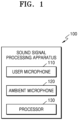
- FIG. 1 is a block diagram illustrating a configuration of a sound signal processing apparatus according to an example embodiment.
- the sound signal processing apparatus 100 may include a user microphone 110, an ambient microphone 120, and a processor 130.
- a user microphone 110 In the sound signal processing apparatus 100 illustrated in FIG. 1 , components related to the present embodiments are illustrated. Accordingly, it is apparent to those skilled in the art that general-purpose components other than the components shown in FIG. 1 may further be included in the sound signal processing apparatus 100.
- the sound signal processing apparatus 100 may be a wearable device worn by a user to receive the user's voice. Alternatively, the sound signal processing apparatus 100 is not wearable by the user and may be disposed adjacent to the sound output apparatus or included in the sound output apparatus. However, this is only an example, and the sound signal processing apparatus 100 may be modified and implemented in various forms capable of receiving sound. Examples of the sound signal processing apparatus 100 will be described later with reference to FIG. 16A .
- the sound signal processing apparatus 100 may include different types of microphones to generate various sound signals for the received sound. Even if the same sound is received, the sound signal generated by the microphone may be different according to the configuration and operation of the microphone. Accordingly, the sound signal processing apparatus 100 may generate a target sound signal by including different types of microphones.
- the sound signal processing apparatus 100 may include a user microphone 110 for detecting a user's voice and an ambient microphone 120 for detecting a whole sound including the user's voice. The whole sound may be a mixed sound signal including the user's voice and other ambient sound.
- the user microphone 110 and the ambient microphone 120 may receive the whole sound including the user's voice and an external sound generated from outside the user.
- the user's voice may correspond to the voice of a user who uses or wears the sound signal processing apparatus 100.
- the external sound is a sound received from the outside of the user and may correspond to a sound other than the user's voice.
- the external sound may include a voice of an outsider having a conversation with the user, a sound output from an image viewed by the user, or a sound generated in an environment around the user.
- the whole sound is a sound including both a user's voice and an external sound, and may correspond to all sounds transmitted (or received) to the sound signal processing apparatus 100.
- the whole sound is transmitted (or received by) to the user microphone 110, but external sound may be attenuated from the whole sound by a structure or operation of the user microphone 110, and thus, a user voice signal may be generated.
- the user microphone 110 and the ambient microphone 120 may convert a received sound into an electrical signal including information, such as frequency, amplitude, and time.
- the user microphone 110 may generate a user voice signal by attenuating an external sound from the whole received sound.
- the user microphone 110 may generate a further clearer user voice signal by attenuating the external sound.
- the user microphone 110 may have directivity with respect to a user's voice in order to attenuate a received external sound.
- the user microphone 110 may attenuate a signal corresponding to the external sound based on a threshold value. The configuration and operation of the user microphone 110 will be described later with reference to FIG. 2 .
- the user microphone 110 may receive a sound through one plane formed by the user microphone 110.
- the one plane may denote a plane formed by a vibrating unit of the user microphone 110 or may denote a plane formed by a plurality of vibrating units arranged in a plane.
- the user microphone 110 may be arranged in the sound signal processing apparatus 100 so that the one plane formed by the user microphone 110 is disposed in a direction corresponding to the point of utterance of the user's voice, or to face the positon of utterance of the user's voice. Due to the arrangement of the user's microphone 110, the user's voice may be sensed with a high sensitivity and an external sound may be sensed with a low sensitivity. Accordingly, an external sound is attenuated from the whole sound received by the user microphone 110, and the user voice signal, which is a sound signal generated by the user microphone 110, may be a signal from which the external sound is attenuated.
- the user microphone 110 may be disposed in the sound signal processing apparatus 100 so that an angle formed between the one plane receiving the whole sound and a direction from the utterance point of the user's voice to the one plane is in a range of 60° to 120°.
- the arrangement of the user microphone 110 (or the vibrator of the user microphone) will be described later with reference to FIGS. 10A and 10B .
- the ambient microphone 120 may generate a whole sound signal from the received whole sound.
- the ambient microphone 120 may generate a whole sound signal from which neither the user's voice nor the external sound is attenuated or emphasized.
- the processor 130 may receive the sound signals generated by microphones and perform an operation with respect to the received sound signals.
- the processor 130 may generate an external sound signal by differentially calculating the user voice signal from the whole sound signal.
- the external sound signal may be a signal from which a signal corresponding to the user's voice is attenuated from the whole sound signal. Accordingly, the external sound signal may include only a signal corresponding to the external sound or may be a signal in which a signal corresponding to the external sound is emphasized.
- the emphasis of a specific signal does not mean that the specific signal is amplified, but rather that the specific signal becomes clear as other signals are attenuated.
- a method for the processor 130 to perform the difference operation will be described later with reference to FIGS. 13 and 14 .
- the processor 130 may be implemented as an array of a plurality of logic gates, or may be implemented as a combination of a general-purpose microprocessor and a memory in which a program executable in the microprocessor is stored.
- a general-purpose microprocessor and a memory in which a program executable in the microprocessor is stored.
- the present embodiment may be implemented in other types of hardware.
- the sound signal processing apparatus 100 may generate a user voice signal separately from an external sound signal, it is possible to distinguish the user's voice and the external sound from whole received sounds. That is, even when a user's voice and an external sound are simultaneously received by the sound signal processing apparatus 100, the sound signal processing apparatus 100 may distinguish each sound and generate a signal corresponding to each sound. Accordingly, the sound signal processing apparatus 100 may perform a function or process a command corresponding to each of a user's voice and an external sound in any sound environment.
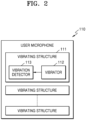
- FIG. 2 is a block diagram illustrating a configuration of a user microphone 110 according to an example embodiment.
- the user microphone 110 may include a plurality of vibration structures 111.
- Each vibration structure 111 may include a vibrator 112 and a vibration detector 113.
- the user microphone 110 shown in FIG. 2 components related to the present embodiments are shown. Accordingly, it is apparent to those skilled in the art that other general-purpose components other than the components shown in FIG. 2 may further be included in the user microphone 110.
- the user microphone 110 may further include a support or a sound controller.
- the user microphone 110 may include a plurality of vibration structures 111 configured to sense sounds of different frequency bands.
- the plurality of vibration structures 111 may be formed in different shapes (e.g., length, thickness, shape, weight, etc.) and may have a resonant frequency corresponding to the shape.
- the plurality of vibration structures 111 may sense sound in a frequency band corresponding to each resonant frequency. A detailed structure of the vibration structure 111 will be described later with reference to FIGS. 3 and 4A .
- the vibrator 112 may vibrate as the whole sound is received.
- the vibrator 112 may vibrate as a sound having a frequency close to the resonant frequency of the vibrator 112 is received.
- Each vibrator 112 may form a plane for receiving a whole sound.
- the vibrators 112 are arranged in a plane within the user microphone 110, the user microphone 110 may form one plane corresponding to a plurality of planes of the vibrators 112.
- the vibrator 112 may vibrate in a direction orthogonal to one plane based on the frequency of the whole sound.
- One plane formed by the vibrator 112 will be described later with reference to FIG. 4A .
- the vibration detector 113 may receive the vibration of the vibrator 112 and generate an electrical signal corresponding to the received vibration. As the vibration is converted into an electrical signal by the vibration detector 113, the sound signal processing apparatus 100 may perform various processes and operations on the received sound.
- FIG. 3 is a diagram illustrating a configuration of the user microphone 110.
- the user microphone 110 may include a support 115 and a plurality of vibration structures 111.
- the support 115 may be formed to support the plurality of vibration structures 111 in a cavity (or a through-hole) 116.
- the support 115 may be a silicon substrate, but is not limited thereto.
- the plurality of vibration structures 111 may be arranged in a predetermined shape on the cavity 116 of the support 115.
- the vibration structures 111 may be arranged in a plane without overlapping each other.
- Each vibrating structure 111, as shown, may be arranged so that one side is fixed to the support 115 and the other side extends toward the cavity 116.
- the vibration structure 111 may be configured to sense, for example, sound frequencies of different bands. That is, the vibration structures 111 may be configured to have different center frequencies or resonant frequencies. To this end, the vibration structure 111 may be provided to have different dimensions. The dimension of the vibrating structure 111 may be set in consideration of a resonant frequency desired for the vibrating structure 111.
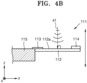
- FIGS. 4A to 4C are cross-sectional views illustrating a vibration structure 111 of FIG. 3 .
- the vibration structure 111 may include the vibrator 112, the vibration detector 113, and a mass body 114. As shown, the vibrating structure 111 may be arranged so that one side is fixed to the support 115 and the other side extends toward the cavity 116.
- Each vibration structure 111 may include the vibrator 112 configured to vibrate in response to an input sound, and the vibration detector 113 configured to sense the movement of the vibrator 112.
- the vibrating structure 111 may further include the mass body 114 for providing a predetermined mass to the vibrator 112.
- the vibrator 112 may vibrate based on a frequency of a received sound.
- the vibrator 112 may vibrate significantly as the frequency of the received sound approaches the resonant frequency, and vibrates slightly as the frequency of the received sound is farther from the resonant frequency.
- the vibrator 112 may vibrate when a sound of a sensible frequency band is received, and may not vibrate when a sound outside the sensible frequency band is received.
- the vibrator 112 may have a cantilever structure that extends horizontally, and is supported at only one end.
- the vibrator 112 may be formed as a beam or plate, and one end of the beam is connected to the support 115 and an opposing end of the beam overhangs without additional support.
- the vibrator 112 may form a plane 112a for receiving a sound.
- the vibrator 112 may vibrate in a direction orthogonal to the one plane 112a as the whole sound is received.
- the vibrator 112 may vibrate with an intensity based on an angle between the propagation direction 41 of a receiving sound and the one plane 112a.
- the vibrator 112 may vibrate with a large vibration intensity as the angle between the propagation direction 41 of the sound and the plane 112a approaches 90°, and vibrates with a small vibration strength as the angle approaches 0°.
- the vibrator 112 when a sound propagating at an angle of 90° with respect to one plane 112a is received, the vibrator 112 may vibrate with the greatest vibration intensity.
- the vibrator 112 when a sound propagating at an angle less than 90° with respect to one plane 112a is received, the vibrator 112 may vibrate with a vibration intensity less than that in FIG. 4B .
- the user's microphone 110 may be arranged in the sound signal processing apparatus 100 in consideration of the sound propagation direction 41.
- the user's microphone 110 may be arranged in the sound signal processing apparatus 100 so that the user's voice is propagated to the plane 112a at an angle close to 90°.
- the user's microphone 110 may be arranged so that the one plane 112a faces an utterance point of the user's voice, and this arrangement will be described later with reference to FIGS. 10A and 10B .
- FIG. 5 is a diagram for explaining a sound sensing method using ambient microphones according to a comparative example.
- the sound sensing method according to the comparative example of FIG. 5 may use a plurality of ambient microphones 510 to maximize sound in a specific direction.
- the plurality of ambient microphones 510 are arranged with a predetermined interval D, due to the interval D, a time or phase delay for sound to reach each ambient microphone 510 occurs, and by varying the degree of compensating for the time or phase delay occurred, the overall directivity may be adjusted.
- This directivity control method may be referred to as Time Difference of Arrival (TDOA).
- the method described above assumes that there is a difference in the time for sound to reach each ambient microphone 510, and because the interval must be set in consideration of a wavelength of an audible frequency band, there may be a restriction in setting the interval between the ambient microphones 510. Because there is a restriction in setting the interval, there may be a restriction on the miniaturization of the apparatus for performing the above-described method. In particular, because the low frequency has a long wavelength, the interval between the ambient microphones 510 is set to be wide in order to distinguish the low frequency sound, and a signal-to-noise ratio (SNR) of each ambient microphone 510 must be high.
- SNR signal-to-noise ratio
- the method described above because the phase is different according to the frequency band of the sound sensed by each ambient microphone 510, it may be necessary to compensate the phase for each frequency.
- the method described above may require a complex signal processing process of applying an appropriate weight to each frequency.
- the sound signal processing apparatus 100 may not require restrictions on the distance between microphones.
- the sound signal processing apparatus 100 may acquire sound in a specific direction by distinguishing directions using a simple operation without complex signal processing.
- an efficient structure and operation of the sound signal processing apparatus 100 will be described in detail with reference to the drawings.
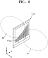
- FIG. 6 is a diagram for describing a directivity pattern of a user's microphone 110 according to an example embodiment.
- the user microphone 110 may have bi-directional signal patterns 61 and 62.
- the bi-directional signal patterns 61 and 62 may be a figure-8 directional pattern including a front plane unit 61 oriented toward a front (+z direction) of the user microphone 110 and a rear plane unit 62 oriented toward a rear (-z direction) of the user microphone 110.
- a directivity pattern may be formed based on sensitive directions of the front direction (+z direction) and the rear direction (-z direction) of the user microphone 110, which is a direction orthogonal to the one plane 112a.
- the sensitivity of the user's microphone 110 to the sound may reduce when the user's microphone 110 moves off-axis and the sound is received in a non-sensitive direction (e.g., +x direction and -x direction).
- the user's microphone 110 may attenuate a sound received in a non-sensitive direction (e.g., +x direction and -x direction).
- a unidirectional signal pattern in the +z direction or -z direction may be formed by blocking the reception of sound on one plane.
- the directivity patterns described above of the user microphone 110 are merely examples, and the directivity patterns may be variously modified according to the arrangement of the vibrating structures 111 (or vibrators 112).
- FIG. 7 is a diagram illustrating a result of measuring a directivity pattern of a user's microphone.
- the user's microphone has a uniformly bi-directional signal pattern with respect to various frequencies. That is, it may be confirmed that a 0° direction and a 180° direction for various frequencies have directivity in the +z axis direction and the -z axis direction of FIG. 6 .
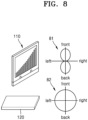
- FIG. 8 is a diagram for describing a signal processing of a sound signal processing apparatus according to an example embodiment.
- the user microphone 110 may have a bi-directional signal pattern 81, and the ambient microphone 120 may have an omni-directional or non-directional signal pattern 82.
- the user microphone 110 may sense a sound that is inphase with a phase of the sound sensed by the ambient microphone 120 from a front direction of the bi-directional signal pattern 81 (e.g., +z direction in FIG. 6 ), and a sound that is anti-phase to a phase of a sound sensed by the ambient microphone 120 from a rear direction (e.g., -z direction in FIG. 6 ).
- the directivity pattern of the user microphone 110 shown in FIG. 8 is merely an example, and as described above, the directivity pattern may be variously modified according to the structure of the user microphone 110 and the arrangement of vibration structures 111 (or vibrators).
- FIG. 9 is a graph showing a result of measuring directivity patterns of a user microphone and an ambient microphone according to an example embodiment.
- the user microphone has a bi-directional signal pattern
- the ambient microphone has an omni-directional (or non-directional) signal pattern.
- the user microphone may sense a sound transmitted from a 330° to 30° area (60° to 120° based on one plane formed by the user microphone) corresponding to a front plane (+z direction in FIG. 6 ), and sense a sound transmitted from a 150° to 210° area (240° to 300° based on one plane formed by the user microphone) corresponding to a rear plane (-z direction in FIG. 6 ).
- the user's microphone may sense approximately 0.85 times the size of sound in the area of 30° (120° based on one plane formed by the user's microphone) compared to the area of 0° (90° based on one plane formed by the user's microphone).
- the ambient microphone may sense sound transmitted from all directions in the surrounding 360° area.
- the user's microphone may attenuate a sound received in a direction close to 90° or 270° (0° based on one plane formed by the user's microphone).
- the user microphone according to an example embodiment responds with a low sensitivity to a sound received in a direction in an angle range of 60° to 120°, the sound in the corresponding direction may be attenuated.
- FIG. 9 shows the results for only one frequency, as described above with reference to FIG. 7 , because the user microphone may have uniform sensitivity to various frequencies, the results for various frequencies may also form a directivity pattern of a similar shape.
- the various frequencies may be frequencies in an audible frequency region, and a directivity pattern having a similar shape may be formed with respect to the user microphone regardless of the high or low frequency.
- FIGS. 10A and 10B are diagrams illustrating an arrangement of a vibrator with respect to an utterance point of a user's voice.
- a user's voice propagated from an utterance point 42 of the user's voice may be received on one plane 112a formed by the vibrator 112.
- the vibrator 112 responds most sensitively, and the user's voice may be sensed the greatest. Accordingly, the user microphone may be disposed in the sound signal processing apparatus so that one plane 112a formed by the vibrator 112 (or a plurality of vibrators) is disposed in a direction corresponding to the utterance point 42 of the user's voice.
- the user microphone may be arranged so that the plane 112a formed by the vibrator 112 (or a plurality of vibrators) and a direction from the utterance point 42 of the user's voice towards the one plane 112a correspond to each other (preferably 90°).
- an angle between the one plane 112a and the propagation direction of the user's voice is 90°, a sound may be sensed with the greatest sensitivity, but the angle may be difficult to be maintained at 90° due to various restrictions in process or use.
- the direction of propagation of the user's voice and one plane 112a may form an angle of less than 90°.
- the user microphone may sense the user's voice.
- the user microphone may be disposed in the sound signal processing apparatus at an angle for securing flexibility in process and use and effectively sensing the user's voice.
- the user microphone may be disposed in the sound signal processing apparatus so that an angle formed between the one plane 112a formed by the vibrator 112 (or a plurality of vibrators) and a direction of the user's voice utterance point 42 toward the one plane 112a is in a range of 60° to 120°.
- the angle in a range from 60° to 120° may be an angle sufficient to provide flexibility in process and use and to sense a user's voice.
- the user microphone when the user microphone is disposed to face the utterance point 42 of the user's voice, the user microphone may respond with a low sensitivity to an external sound generated at a location separated from the utterance point 42 of the user's voice. Accordingly, the user microphone may attenuate the external sound.
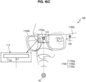
- FIG. 16C An example embodiment in which the user microphone is applied to a sound signal processing apparatus will be schematically described with reference to FIG. 16C .
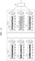
- FIG. 11 is a diagram illustrating a sound adjustment process of a sound adjustment unit according to an example embodiment.
- FIG. 11 shows electrical sound signal frames 1110a to 1110f generated by three vibration structures that sense different frequency bands in each of two time frames.
- Each of the electrical sound signal frames 1110a to 1110f shows sound waveforms in a time domain.
- the sound signal frames are input to sound control units 1100, and each of the sound control units 1100 may be included in each of vibration structures or in a user's microphone.
- the sound control unit 1100 of the user's microphone may determine an electrical signal to be attenuated from among the electrical signals generated by the vibration structures based on a threshold value.
- the sound control unit 1100 may attenuate the determined electrical signal.
- the electrical signal to be attenuated may be a signal corresponding to an external sound.
- the user's voice may be maximized.
- “Frame 0” indicates a sound signal frame measured at a first time interval.
- “Frame j” indicates a sound signal frame measured in a j-th time interval after the first time interval.
- the first to third sound signal frames 1110a to 1110c are frames measured in the same time period (the first time period), and the fourth to sixth sound signal frames 1110d to 1110f are also frames measured in the same time period (the j-th time period).
- the first and fourth sound signal frames 1110a and 1110d may be in the same frequency band and may be input to the sound control unit 1100 through the same vibration structure.
- the second and fifth sound signal frames 1110b and 1110e may be in the same frequency band and may be input to the sound control unit 1100 through the same vibration structure.
- the third and sixth sound signal frames 1110c and 1110f may be in the same frequency band and may be input to the sound control unit 1100 through the same vibration structure.
- the frequency bands of the first and fourth sound signal frames 1110a and 1110d, the frequency bands of the second and fifth sound signal frames 1110b and 1110e, and the frequency bands of the third and sixth sound signal frames 1110c and 1110f are different from each other.
- “Drop” indicates a case in which the sound control unit 1100 determines that an input sound signal is to be attenuated
- “Add” indicates a case in which the sound control unit 1100 does not attenuate the input sound signal.
- the sound control unit 1100 may attenuate the corresponding sound signal (Drop).
- the sound control unit 1100 may not attenuate the corresponding sound signal (Add).
- the sound control unit 1100 may include a switch and an attenuator (or an attenuator circuit). When the input sound signal exceeds the threshold value T, the sound control unit 1100 may turn on the switch to pass the input sound signal to the attenuator, and the attenuator may reduce the power of the input sound signal.
- the attenuator may include resistors that are connected to form a voltage divider. When the input sound signal is less than or equal to the threshold value T, the sound control unit 1100 may turn off the switch to block the input sound signal from flowing into the attenuator.
- An output result of the sound control unit 1100 may be transmitted to the processor 130 through, for example, an amplifying unit.
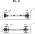
- FIG. 12 is a diagram illustrating a user voice signal generated from a user microphone according to an example embodiment.
- a first graph 1210 showing a result of sensing the user's voice by the method according to the comparative example of FIG. 5 and a second graph 1220 showing a result of sensing the user's voice by the user's microphone are shown.
- the first graph 1210 shows a result of attenuating an external sound by using a plurality of ambient microphones according to the comparative example of FIG. 5 .
- a signal 1210a corresponding to a user's voice and a signal 1210b corresponding to an external sound are shown. It is confirmed that the signal 1210b corresponding to the external sound is attenuated than the signal 1210a corresponding to the user's voice, but it is confirmed that enough signal remains to allow the signal to be sensed.
- the second graph 1220 represents a user voice signal generated by the user's microphone that attenuates an external sound signal.
- a signal 1220a corresponding to a user's voice and a signal 1220b corresponding to an external sound are shown.
- the signal 1220b corresponding to the external sound is significantly attenuated.
- the signal 1220b corresponding to the external sound is attenuated to a level close to silence, which is difficult to be sensed.
- the user's microphone may attenuate an external sound through arrangement toward a point of origin of the user's voice based on the directivity of the vibrating structures.
- the user's microphone may attenuate the external sound by attenuating some of the signals generated by the vibration structures based on a threshold value.
- the user's microphone may attenuate an external sound signal and generate a user voice signal by using one or both of the two methods described above.
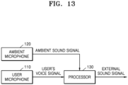
- FIG. 13 is a block diagram for describing a method of calculating a difference according to an example embodiment.
- a whole sound signal generated from the ambient microphone 120 and a user voice signal generated from the user microphone 110 may be input to the processor 130.
- the processor 130 may generate an external sound signal through an operation on the input signals.
- a whole sound signal corresponding to the whole sound may include a signal corresponding to the external sound and a signal corresponding to the user's voice.
- the whole sound signal may be a signal from which no sound of any kind is attenuated or emphasized.
- the user voice signal may be a signal from which the external sound is attenuated from the whole sound by sensing the user's voice with a high sensitivity and sensing the external sound with a low sensitivity.
- the processor 130 may generate a signal from which a signal corresponding to the user's voice is attenuated from the whole sound signal and a signal corresponding to the external sound is maintained by differentially calculating the user voice signal from the whole sound signal. In this way, the processor 130 may generate an external sound signal in which a signal corresponding to the external sound is emphasized.
- FIG. 14 is a block diagram for explaining an example of the method of calculating the difference of FIG. 13 .
- a user voice signal generated from the user microphone 110 may be input to an adaptive filter 1400.
- An output signal of the adaptive filter 1400 may be differentially calculated from a whole sound signal generated from the ambient microphone 120, and a feedback signal which is a signal resulted from the differential calculation may be input to the adaptive filter 1400.
- an external sound signal may be finally generated.
- the adaptive filter 1400 may adjust parameters for combining the ambient sound signal and the user's voice signal, based on the feedback signal.
- the parameters may be adjusted so that the user's voice is attenuated from the whole sound signal as a result of the differential calculation.
- the adaptive filter 1400 may be operated according to various algorithms, for example, a least squares mean (LMS) algorithm for minimizing an error signal, a filtered-X LMS (FXLMS) algorithm, a filterederror LMS (FELMS) algorithm, steepest descent algorithm, or a recursive least squares (RLS) algorithm.
- the parameters may include parameters relating to, for example, a correlation coefficient between signals, a delay of signals, or an amplitude of signals.
- the correlation coefficient may include a Spearman correlation coefficient, a Cronbach's alpha coefficient, or a Pearson correlation coefficient.
- the processor may generate an external sound signal through an operation on the input signals.
- the processor may generate a feedback signal by differentially calculating a signal output from the adaptive filter 1400 from all sound signals.
- the processor may control the adaptive filter 1400 to adjust parameters by inputting the feedback signal to the adaptive filter 1400.
- the processor may generate an external sound signal from which a signal corresponding to the user's voice is attenuated by differentially calculating the output signal from the adaptive filter 1400, in which parameters are adjusted as the feedback signal is applied, from the whole sound signal.
- the sound signal processing apparatus may perform a differential calculation through a neural network operation without using the adaptive filter 1400.
- the sound signal processing apparatus may perform a differential calculation through a convolution neural network (CNN) operation, a deep neural network (DNN) operation, or a recurrent neural network (RNN) operation.
- CNN convolution neural network
- DNN deep neural network
- RNN recurrent neural network
- the type of neural network employed in the sound signal processing apparatus is not limited thereto.
- FIG. 15 is a diagram illustrating an external sound signal according to an example embodiment.
- a first graph 1510 showing a sound signal output by the method according to the comparative example of FIG. 5 and a second graph 1520 showing an external sound signal generated by the sound signal processing apparatus are shown.
- a signal 1510b corresponding to an external sound and a signal 1510a corresponding to a user's voice are shown.
- a signal 1520b corresponding to an external sound and a signal 1520a corresponding to a user's voice are also shown.
- the first graph 1510 represents a sound signal output by using a plurality of ambient microphones according to the comparative example of FIG. 5 . It is confirmed that the signal 1510a corresponding to the user's voice started at a point close to the ambient microphone is emphasized and the signal 1510b corresponding to the external sound is attenuated. According to the first graph 1510, in the comparative example of FIG. 5 , an external sound is not clearly sensed, and functions according to the external sound are also difficult to perform.
- the second graph 1520 also represents an external sound signal generated by the sound signal processing apparatus. It is confirmed that the signal 1520a corresponding to the user's voice is attenuated despite the close proximity of the user's microphone and the ambient microphone to the utterance point of the user's voice. On the other hand, it is confirmed that the signal 1520b corresponding to the external sound is emphasized. According to the second graph 1520, the sound signal processing apparatus may clearly sense an external sound while excluding the user's voice, and accordingly, may perform a corresponding function in response to the external sound.
- the signal 1510b corresponding to the external sound was measured as -34.45 dB, and the signal 1510a corresponding to the user's voice was measured as -17.76 dB.
- the signal 1520b corresponding to the external sound was measured as -19.98 dB, and the signal 1520a corresponding to the user's voice was measured as -25.41 dB. Accordingly, differences between the signals 1510a and 1520a corresponding to the user's voice and the signals 1510b and 1520b corresponding to the external sound are -16.69 dB in the first graph 1510 and 5.43 dB in the second graph 1520.
- FIGS. 16A to 16C are diagrams illustrating embodiments in which the sound signal processing apparatus is a glasses-type wearable apparatus.
- the sound signal processing apparatus 100 is a glasses-type wearable apparatus and may include a glasses frame 1700.
- the glasses frame 1700 may include a glasses bridge 1700a, a glasses frame 1700b, and a glasses leg 1700c.
- a user microphone and an ambient microphone may be disposed on the glasses frame 1700.
- the user microphone and the ambient microphone may be disposed in various positions of the glasses frame 1700 according to the sound to be received.
- the user's microphone may be disposed on the glasses bridge 1700a or the glasses frame 1700b to receive the user's voice at a closer position.
- the ambient microphone may be disposed on the glasses frame 1700b or the glasses leg 1700c.
- the sound signal processing apparatus 100 is a glasses-type wearable apparatus, this is only an example, and the sound signal processing apparatus 100 is in the form of a watch or bracelet worn on a wrist, in the form of a necklace worn on the neck, or in various types of wearable devices, such as earphones and headphones worn on the ears.
- the sound signal processing apparatus 100 may correspond to any wearable apparatus without limitation as long as it is wearable.
- the user microphone 110 is disposed on the glasses bridge 1700a of the sound signal processing apparatus 100 and the ambient microphone 120 is disposed on the glasses leg 1700c of the sound signal processing apparatus 100.
- the user's microphone 110 may be disposed on the glasses bridge 1700a to correspond to the utterance point.
- the ambient microphone 120 may be disposed on the glasses leg 1700c so as to more effectively receive an external sound in a lateral direction of the user and to be far from an utterance point of the user's voice.
- microphones may be disposed at various locations within the glasses frame 1700.
- a user's voice is propagated from the utterance point 42 of the user's voice to the user's microphone 110.
- the utterance point 42 of the user's voice may be a position corresponding to the user's mouth or lips.
- the user's voice is propagated to the user's microphone 110 and may be received on the one plane 112a formed by the vibrator 112 of the user's microphone 110.
- the user's voice may be sensed with the greatest sensitivity by the user's microphone 110.
- the user's microphone 110 may be disposed in the sound signal processing apparatus 100 so that a direction from the utterance point 42 of the user's voice to the one plane 112a is vertical.
- the outsider's voice may be sensed with the lowest sensitivity or may not be sensed by the user's microphone 110. Due to this arrangement, the user's microphone 110 may attenuate an external sound and emphasize the user's voice.
- the user microphone 110 may be disposed so that an angle between the direction of the user's voice and the one plane 112a is in a range of 60° to 120°. As described above with reference to FIGS. 9 and 10B , even when the user's microphone 110 is disposed at the angle described above, the user's voice may be effectively sensed, and thus, an external sound signal from which the user's voice is attenuated may be generated.
- FIG. 17 is a block diagram illustrating a configuration of a sound signal processing apparatus 1900 according to another example embodiment.
- the sound signal processing apparatus 1900 may include a user microphone 1910, an ambient microphone 1920, and a processor 1930.
- the sound signal processing apparatus 1900 illustrated in FIG. 17 only components related to the present embodiments are illustrated. Accordingly, it is apparent to those skilled in the art that general-purpose components other than those shown in FIG. 17 may further be included in the sound signal processing apparatus 1900.
- the user microphone 1910 of FIG. 17 corresponds to the user microphone of FIG. 1
- the ambient microphone 1920 of FIG. 17 has a structure and operation method different from the ambient microphone of FIG. 1 and the ambient microphone of FIG. 5 , and may have a structure similar to that of the user microphone of FIG. 1 .
- the ambient microphone 1920 may have a structure corresponding to the user microphone 1910.
- the ambient microphone 1920 may include a plurality of vibration structures like the user microphone 1910, and may be arranged in the sound signal processing apparatus 1900 in consideration of the propagation direction of the received sound.
- the user microphone 1910 forms a first plane and may receive a sound through the first plane.
- the user microphone 1910 may be arranged in the sound signal processing apparatus 1900 so that the first plane is arranged in a direction corresponding to an utterance point of the user's voice. Due to this arrangement, the user microphone 1910 may generate a user voice signal from which an external sound is attenuated.
- the ambient microphone 1920 forms a second plane and may receive sound through the second plane.
- the ambient microphone 1920 may be arranged in the sound signal processing apparatus 1900 so that the second plane is arranged in a direction different from the direction in which the user microphone is arranged. Therefore, because the ambient microphone 1920 is not arranged to correspond to an utterance point of the user's voice, in the ambient microphone 1920, a sound signal from which the user's voice is attenuated compared to the sound signal generated by the user microphone 1910 may be generated.
- the ambient microphone 1920 may be provided in the sound signal processing apparatus 1900 so that the second plane is arranged in a direction corresponding to the point where the external sound is generated. Due to the arrangement of the ambient microphone 1920, an external sound may be sensed with a high sensitivity and a user's voice may be sensed with a low sensitivity. Accordingly, the user's voice may be attenuated from a whole sound received by the ambient microphone 1920, and a first external sound signal that is a sound signal generated by the ambient microphone 1920 may be a signal from which the user's voice has been attenuated.
- the processor 1930 may generate a second external sound signal by differentially calculating the user voice signal from the first external sound signal. Although the user's voice has already been attenuated and sensed in the first external sound signal, the processor 1930 may generate a second external sound signal from which the user's voice is further attenuated by differentially calculating the user voice signal of the user's microphone 1910 from the first external sound signal of the ambient microphone 1920.
- FIG. 18 is a diagram for explaining the arrangement of the user microphone 1910 and the ambient microphone 1920 according to the embodiment of FIG. 17 .
- the user's voice propagated from an utterance point 42 of the user's voice may be received on a first plane 1912a formed by the vibrator 1912 of the user's microphone 1910.
- an external sound propagated from an external sound generating point 43 may be received by the second plane 1922a formed by the vibrator 1922 of the ambient microphone 1920.
- the vibrator 1912 may respond most sensitively and the user's voice may be sensed the greatest. Accordingly, the user's microphone 1910 may be disposed in the sound signal processing apparatus so that the first plane 1912a formed by the vibrator 1912 (or a plurality of vibrators) is disposed in a direction corresponding to the utterance point 42 of the user's voice.
- the user microphone 1910 may be arranged so that the first plane 1912a formed by the vibrator 1912 (or a plurality of vibrators) and a direction from the utterance point 42 of the user's voice toward the first plane 1912a correspond to each other (preferably, to form 90°).
- the user microphone 1910 may be arranged in the sound signal processing apparatus so that an angle formed between the first plane 1912a formed by the vibrator 1912 (or a plurality of vibrators) and the direction from the utterance point 42 of the user's voice towards the first plane 1912a is in a range of 60° to 120°.
- the vibrator 1922 may respond most sensitively, and the external sound may be sensed the greatest. Accordingly, the ambient microphone 1920 may be arranged in the sound signal processing apparatus so that the second plane 1922a formed by the vibrator 1922 (or a plurality of vibrators) is arranged in a direction corresponding to the external sound generating point 43.
- the ambient microphone 1920 may be arranged so that the second plane 1922a formed by the vibrator 1922 (or a plurality of vibrators) and the direction from the external sound generating point 43 toward the second plane 1922a correspond to each other (preferably to form 90°).
- the ambient microphone 1920 may be arranged in the sound signal processing apparatus so that an angle formed between the second plane 1922a formed by the vibrator 1922 (or a vibrators) and the direction from the external sound generation point 43 toward the second plane 1922a is in a range of 60° to 120°.
- the external sound is received at an angle away from 90° (or at an angle close to parallel) on the first plane 1912a of the user microphone 1910
- the user's voice is received at an angle away from 90° (or at an angle close to parallel) on the second plane 1922a of the ambient microphone 1920.
- an external sound may be sensed with a low sensitivity to the user's microphone 1910
- a user's voice may be sensed with a low sensitivity to the ambient microphone 1920. That is, the user microphone 1910 may generate a user voice signal from which an external sound is attenuated, and the ambient microphone 1920 may generate a first external sound signal from which the user's voice is attenuated.
- the user's microphone may be arranged in the sound signal processing apparatus so that the first plane 1912a is arranged in a direction corresponding to the user's lips or oral cavity.
- the ambient microphone may be arranged in a direction different from the direction in which the user's microphone is arranged, and may be arranged in the sound signal processing apparatus so that the second plane 1922a is arranged in a direction corresponding to the front or side of the user.
- the direction in which the second plane 1922a of the ambient microphone is arranged is not limited to the front or side of the user, and may be arranged in various directions according to design.
- FIG. 19 is a block diagram for explaining a differential calculation method according to the embodiment of FIG. 17 .
- a first external sound signal generated from the ambient microphone 1920 and a user voice signal generated from the user microphone 1910 may be input to the processor 1930.
- the processor 1930 may generate a second external sound signal through a calculation on the input signals.
- the first external sound signal may be a signal from which the user's voice is attenuated from a whole sound by sensing the external sound with a high sensitivity and the user's voice with a low sensitivity.
- the user voice signal may be a signal from which the external sound is attenuated from the whole sound by sensing the user's voice with a high sensitivity and sensing the external sound with a low sensitivity.
- the processor 1930 may generate a signal from which a signal corresponding to the user's voice in the first external sound signal is further attenuated and a signal corresponding to the external sound is maintained by differentially calculating the user voice signal from the first external sound signal.
- the processor 1930 may perform a differential calculation between signals by using an adaptive filter or a neural network.
- FIG. 20 is a block diagram illustrating a configuration of a sound signal processing apparatus according to another example embodiment.
- the sound signal processing apparatus 2200 may include a directivity microphone 2210, an ambient microphone 2220, and a processor 2230.
- the sound signal processing apparatus 2200 may receive an output sound from a sound output apparatus 2300.
- FIG. 20 only components related to the present embodiments are illustrated. Accordingly, it is apparent to those skilled in the art that other general-purpose components other than the components shown in FIG. 20 may further be included in the sound signal processing apparatus 2200.
- the directivity microphone 2210 of FIG. 20 may correspond to the user microphone of FIG. 1 .
- the sound signal processing apparatus 2200 is not worn by the user and may be arranged adjacent to the sound output apparatus 2300 or included in the sound output apparatus 2300.
- the output sound of the embodiment of FIG. 20 may correspond to the user's voice of the embodiment of FIG. 1 .
- the sound signal processing apparatus 2200 attenuates a user's voice generated at a nearby location through a differential calculation
- the sound signal processing apparatus 2200 is located close to the sound output apparatus 2300, an output sound generated at a nearby location may be attenuated through a differential calculation.
- the sound signal processing apparatus 2200 generates an external sound from which an output sound is attenuated, but the external sound may include a user's voice.
- the sound output apparatus 2300 may generate an external sound signal from which an output sound is attenuated and a user's voice is emphasized while receiving the output sound.
- the directivity microphone 2210 may receive a whole sound including a sound output from the sound output apparatus 2300 and an external sound generated from the outside of the sound output apparatus 2300.
- the directivity microphone 2210 may generate an output sound signal by attenuating an external sound from the whole received sound.
- the directivity microphone 2210 may be disposed in the sound signal processing apparatus 2200 so that one plane that receives the whole sound is arranged in a direction corresponding to a point of generation of the output sound. Due to the arrangement of the directivity microphone 2210, an output sound may be sensed with a high sensitivity and an external sound may be sensed with a low sensitivity. Accordingly, an external sound may be attenuated from the whole sound received by the directivity microphone 2210, and an output sound signal that is a sound signal generated by the directivity microphone 2210 may be a signal from which the external sound has been attenuated.
- the directivity microphone 2210 may be arranged so that an angle formed between a plane for receiving a sound and a direction towards the plane from a point of generating an output sound is in a range of 60° to 120°.
- the ambient microphone 2220 may receive a whole sound and may generate an whole sound signal from the received whole sound.
- the processor 2230 may generate an external sound signal from which the output sound is attenuated by differentially calculating the output sound signal from the whole sound signal.
- the sound signal processing apparatus 2200 of FIG. 20 differs only in the type of signal to be attenuated or emphasized, but the operation method and arrangement thereof correspond to the sound signal processing apparatus of FIG. 1 , and thus redundant descriptions of the sound signal processing apparatus 2200 are herein omitted.
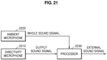
- FIG. 21 is a diagram for explaining a differential calculation method according to the embodiment of FIG. 20 .
- a whole sound signal generated from the ambient microphone 2220 and an output sound signal generated from the directivity microphone 2210 may be input to the processor 2230.
- the processor 2230 may generate an external sound signal through a calculation on the input signals.
- the whole sound signal corresponding to the whole sound may include a signal corresponding to the external sound and a signal corresponding to the output sound.
- the external sound may include a user's voice.
- the whole sound signal may be a signal from which no sound of any kind is attenuated or emphasized.
- the output sound signal may be a signal from which the external sound is attenuated from the whole sound by sensing the output sound with a high sensitivity and the external sound with a low sensitivity.
- the processor 2230 may generate a signal from which a signal corresponding to the output sound is attenuated from the whole sound signal and a signal corresponding to the external sound (or user voice) is maintained by differentially calculating the output sound signal from the whole sound signal. In this way, the processor 2230 may generate an external sound signal in which a signal corresponding to the external sound is emphasized.
- the processor 2230 may perform a differential calculation between signals by using an adaptive filter or a neural network.
- FIG. 22 is a flowchart illustrating a method of processing a sound signal, according to an example embodiment.
- the method of processing a sound signal includes operations processed in time series by the sound signal processing apparatus shown in FIG. 1 . Therefore, it may be seen that the above-described information regarding the sound signal processing apparatus with reference to FIG. 1 and the like is also applied to the method of FIG. 22 even if the content is omitted below.
- the sound signal processing apparatus may receive a whole sound including a user's voice and an external sound generated from an outside of the user.
- a plurality of vibration structures sensing sound of different frequency bands may vibrate in a direction orthogonal to one plane formed to receive the whole sound based on the frequency of the received whole sound.
- the sound signal processing apparatus may vibrate with a vibration intensity based on an angle between a propagation direction of a received sound and an angle formed by one plane.
- the sound signal processing apparatus may vibrate with a high vibration intensity as the angle approaches 90°, and vibrates with a low vibration intensity as the angle approaches 0°.
- the sound signal processing apparatus may generate an electrical signal corresponding to the vibration of each of the plurality of vibration structures.
- the sound signal processing apparatus may generate a whole sound signal from the received whole sound.
- the sound signal processing apparatus may generate a user voice signal from which an external sound is attenuated from the whole received sound.
- the sound signal processing apparatus may determine an electrical signal to be attenuated from among electrical signals based on a threshold value, and may attenuate the determined electrical signal.
- the sound signal processing apparatus may determine the threshold value based on an average magnitude of the electrical signals.
- the sound signal processing apparatus may generate an external sound signal from which the user's voice is attenuated by differentially calculating the user voice signal from the whole sound signal.
- the sound signal processing apparatus may generate a feedback signal by inputting a user voice signal to an adaptive filter, and differentially calculating a signal output from the adaptive filter from a whole sound signal, and may control the adaptive filter to adjust parameters by inputting the feedback signal to the adaptive filter.
- the sound signal processing apparatus may perform a function corresponding to a user voice signal and a function corresponding to an external sound signal, and display results of each of the functions in different regions of the display.
- the sound signal processing apparatus may generate a user voice signal without an additional separate operation process, and may generate an external sound signal from which the user's voice is attenuated only through simple calculations on the user voice signal and a whole sound signal.
- the sound signal processing apparatus may perform various functions by using each of the generated user voice signal and the external sound signal.
- the method of FIG. 22 described above may be recorded in a computer-readable recording medium in which one or more programs including instructions for executing the method are recorded.
- Examples of non-transitory computer-readable recording medium include magnetic media, such as hard disks, floppy disks, and magnetic tapes, optical media, such as CD-ROMs and DVDs, magneto-optical media, such as floppy disks, and hardware devices specially configured to store and execute program instructions, such as ROM, RAM, flash memory, and the like.
- Examples of program instructions include not only machine language codes, such as those generated by a compiler, but also high-level language codes that may be executed by a computer using an interpreter or the like.
Landscapes
- Engineering & Computer Science (AREA)
- Signal Processing (AREA)
- Physics & Mathematics (AREA)
- Acoustics & Sound (AREA)
- Health & Medical Sciences (AREA)
- Computational Linguistics (AREA)
- Quality & Reliability (AREA)
- Audiology, Speech & Language Pathology (AREA)
- Human Computer Interaction (AREA)
- Multimedia (AREA)
- Otolaryngology (AREA)
- General Health & Medical Sciences (AREA)
- Circuit For Audible Band Transducer (AREA)
- Obtaining Desirable Characteristics In Audible-Bandwidth Transducers (AREA)
Claims (7)
- Vorrichtung (100) zur Tonsignalverarbeitung, umfassend:ein Richtmikrofon (110), das dazu konfiguriert ist, ein Mischtonsignal zu empfangen, das eine Stimme eines Benutzers und einen externen Ton umfasst, um ein Benutzerstimmsignal zu detektieren, das die Stimme des Benutzers umfasst, und derart konfiguriert ist, dass das Richtmikrofon in Verwendung einem Äußerungspunkt der Stimme des Benutzers zugewandt ist;ein ungerichtetes Mikrofon (120), das dazu konfiguriert ist, das Mischtonsignal zu detektieren, undeinen Prozessor (130), der dazu konfiguriert ist, ein externes Tonsignal zu erzeugen, indem er die Stimme des Benutzers aus dem Mischtonsignal dämpft, indem er das Benutzerstimmsignal aus dem Mischtonsignal differentiell berechnet; und dadurch gekennzeichnet, dassdie Vorrichtung zur Tonsignalverarbeitung eine brillenartige Wearable-Vorrichtung ist, das Richtmikrofon und das ungerichtete Mikrofon an einem Brillengestell (1700) der brillenartigen Wearable-Vorrichtung angeordnet sind und das Richtmikrofon so angeordnet ist, dass eine Ebene zum Empfangen des Mischtons dem Äußerungspunkt der Stimme des Benutzers zugewandt ist, und wobei das Richtmikrofon an einem Brillensteg (1700a) oder dem Brillengestell (1700b) der brillenartigen Wearable-Vorrichtung angeordnet ist und das ungerichtete Mikrofon von dem Richtmikrofon getrennt ist und an einem Gestell oder Bügel (1700c) der brillenartigen Wearable-Vorrichtung angeordnet ist.
- Vorrichtung zur Tonsignalverarbeitung nach Anspruch 1, wobei das Richtmikrofon eine Vielzahl von Schwingungsstrukturen umfasst, die dazu konfiguriert ist, Ton unterschiedlicher Frequenzbänder zu erfassen, wobei jede der Vielzahl von Schwingungsstrukturen einen Schwinger umfasst, der eine Ebene zum Empfangen des Mischtonsignals bildet, und wenn das Mischtonsignal empfangen wird, basierend auf einer Frequenz des Mischtonsignals in einer Richtung orthogonal zu der einen Ebene schwingt, und wobei optional der Schwinger mit einer Schwingungsintensität basierend auf einem Winkel zwischen einer Ausbreitungsrichtung des Mischtonsignals und der einen durch den Schwinger gebildeten Ebene schwingt und wobei ferner optional der Schwinger mit einer höheren Schwingungsintensität schwingt, wenn sich der Winkel 90° nähert, und mit einer niedrigeren Schwingungsintensität schwingt, wenn sich der Winkel 0° nähert.
- Vorrichtung zur Tonsignalverarbeitung nach Anspruch 2, wobei das Richtmikrofon so angeordnet ist, dass ein zwischen der einen Ebene und einer Richtung von dem Äußerungspunkt der Stimme des Benutzers gebildeter Winkel in einem Bereich von 60° bis 120° liegt.
- Vorrichtung zur Tonsignalverarbeitung nach Anspruch 2 oder 3, wobei jede der Vielzahl von Schwingungsstrukturen ferner einen Schwingungsdetektor umfasst, der dazu konfiguriert ist, eine Schwingung des Schwingers zu empfangen.
- Vorrichtung zur Tonsignalverarbeitung nach Anspruch 4, wobei das Richtmikrofon dazu konfiguriert ist, ein zu dämpfendes elektrisches Signal aus durch die Schwingungsstrukturen erzeugten elektrischen Signalen zu bestimmen und das bestimmte elektrische Signal zu dämpfen, und wobei optional das Richtmikrofon ferner dazu konfiguriert ist, einen Schwellenwert basierend auf einer Durchschnittsgröße der durch die Schwingungsstrukturen erzeugten elektrischen Signale zu bestimmen.
- Vorrichtung zur Tonsignalverarbeitung nach einem vorhergehenden Anspruch, ferner umfassend ein adaptives Filter, das dazu konfiguriert ist, Parameter zum Kombinieren des Benutzerstimmsignals und des Mischtonsignals einzustellen, sodass die Stimme des Benutzers basierend auf einem Rückkopplungssignal aus dem Mischtonsignal gedämpft wird,
wobei der Prozessor ferner zu Folgendem konfiguriert ist:Erzeugen des Rückkopplungssignals durch differentielles Berechnen eines aus dem adaptiven Filter ausgegebenen Signals aus dem Mischtonsignal, wenn das Benutzerstimmsignal in das adaptive Filter eingegeben wird; undSteuern des adaptiven Filters, um die Parameter einzustellen, durch Eingeben des Rückkopplungssignals in das adaptive Filter. - Vorrichtung zur Tonsignalverarbeitung nach einem vorhergehenden Anspruch, wobeidas ungerichtete Mikrofon dazu konfiguriert ist, ein erstes externes Tonsignal aus dem Mischtonsignal zu erzeugen, aus dem die Stimme des Benutzers gedämpft ist, indem es eine Ebene, die das Mischtonsignal empfängt, in einer Richtung anordnet, die sich von einer Richtung unterscheidet, in der das Richtmikrofon angeordnet ist; undder Prozessor ferner dazu konfiguriert ist, ein zweites externes Tonsignal zu erzeugen, aus dem die Stimme des Benutzers weiter gedämpft ist als die des ersten externen Tonsignals, indem er das Benutzerstimmsignal aus dem ersten externen Tonsignal differentiell berechnet.
Priority Applications (1)
| Application Number | Priority Date | Filing Date | Title |
|---|---|---|---|
| EP24205029.2A EP4465656A3 (de) | 2021-06-04 | 2022-04-04 | Tonsignalverarbeitungsvorrichtung und tonsignalverarbeitungsverfahren |
Applications Claiming Priority (2)
| Application Number | Priority Date | Filing Date | Title |
|---|---|---|---|
| KR20210072966 | 2021-06-04 | ||
| KR1020210171203A KR20220164395A (ko) | 2021-06-04 | 2021-12-02 | 음향 신호 처리 장치 및 방법 |
Related Child Applications (2)
| Application Number | Title | Priority Date | Filing Date |
|---|---|---|---|
| EP24205029.2A Division-Into EP4465656A3 (de) | 2021-06-04 | 2022-04-04 | Tonsignalverarbeitungsvorrichtung und tonsignalverarbeitungsverfahren |
| EP24205029.2A Division EP4465656A3 (de) | 2021-06-04 | 2022-04-04 | Tonsignalverarbeitungsvorrichtung und tonsignalverarbeitungsverfahren |
Publications (3)
| Publication Number | Publication Date |
|---|---|
| EP4109923A2 EP4109923A2 (de) | 2022-12-28 |
| EP4109923A3 EP4109923A3 (de) | 2023-03-15 |
| EP4109923B1 true EP4109923B1 (de) | 2025-02-12 |
Family
ID=81324919
Family Applications (2)
| Application Number | Title | Priority Date | Filing Date |
|---|---|---|---|
| EP22166574.8A Active EP4109923B1 (de) | 2021-06-04 | 2022-04-04 | Vorrichtung und verfahren zur tonsignalverarbeitung |
| EP24205029.2A Withdrawn EP4465656A3 (de) | 2021-06-04 | 2022-04-04 | Tonsignalverarbeitungsvorrichtung und tonsignalverarbeitungsverfahren |
Family Applications After (1)
| Application Number | Title | Priority Date | Filing Date |
|---|---|---|---|
| EP24205029.2A Withdrawn EP4465656A3 (de) | 2021-06-04 | 2022-04-04 | Tonsignalverarbeitungsvorrichtung und tonsignalverarbeitungsverfahren |
Country Status (3)
| Country | Link |
|---|---|
| US (1) | US12380913B2 (de) |
| EP (2) | EP4109923B1 (de) |
| CN (1) | CN115440241A (de) |
Families Citing this family (2)
| Publication number | Priority date | Publication date | Assignee | Title |
|---|---|---|---|---|
| US12393398B2 (en) | 2021-06-04 | 2025-08-19 | Samsung Electronics Co., Ltd. | Apparatus and method for signal processing |
| US20250358562A1 (en) * | 2024-05-18 | 2025-11-20 | xMEMS Labs, Inc. | Wearable Device and Signal Processing Method |
Family Cites Families (28)
| Publication number | Priority date | Publication date | Assignee | Title |
|---|---|---|---|---|
| US8068619B2 (en) | 2006-05-09 | 2011-11-29 | Fortemedia, Inc. | Method and apparatus for noise suppression in a small array microphone system |
| US7706549B2 (en) | 2006-09-14 | 2010-04-27 | Fortemedia, Inc. | Broadside small array microphone beamforming apparatus |
| JP2010187363A (ja) * | 2009-01-16 | 2010-08-26 | Sanyo Electric Co Ltd | 音響信号処理装置及び再生装置 |
| US20110288860A1 (en) * | 2010-05-20 | 2011-11-24 | Qualcomm Incorporated | Systems, methods, apparatus, and computer-readable media for processing of speech signals using head-mounted microphone pair |
| US9497544B2 (en) | 2012-07-02 | 2016-11-15 | Qualcomm Incorporated | Systems and methods for surround sound echo reduction |
| US20140181741A1 (en) * | 2012-12-24 | 2014-06-26 | Microsoft Corporation | Discreetly displaying contextually relevant information |
| US10229697B2 (en) | 2013-03-12 | 2019-03-12 | Google Technology Holdings LLC | Apparatus and method for beamforming to obtain voice and noise signals |
| WO2014163797A1 (en) | 2013-03-13 | 2014-10-09 | Kopin Corporation | Noise cancelling microphone apparatus |
| US10306389B2 (en) | 2013-03-13 | 2019-05-28 | Kopin Corporation | Head wearable acoustic system with noise canceling microphone geometry apparatuses and methods |
| US10959099B2 (en) * | 2019-01-24 | 2021-03-23 | Natalya Segal | Smart wearable devices and system therefor |
| US9984675B2 (en) * | 2013-05-24 | 2018-05-29 | Google Technology Holdings LLC | Voice controlled audio recording system with adjustable beamforming |
| US10209955B2 (en) | 2013-11-15 | 2019-02-19 | Kopin Corporation | Automatic speech recognition (ASR) feedback for head mounted displays (HMD) |
| KR102195773B1 (ko) | 2013-11-15 | 2020-12-28 | 엘지전자 주식회사 | 안경형 단말기 및 안경형 단말기의 제어방법 |
| US20150281834A1 (en) * | 2014-03-28 | 2015-10-01 | Funai Electric Co., Ltd. | Microphone device and microphone unit |
| JP6514599B2 (ja) | 2014-08-05 | 2019-05-15 | 株式会社ベルウクリエイティブ | 眼鏡型補聴器 |
| KR102207928B1 (ko) | 2014-08-13 | 2021-01-26 | 삼성전자주식회사 | 음향 센싱 소자 및 주파수 정보 획득 방법 |
| EP3422736B1 (de) | 2017-06-30 | 2020-07-29 | GN Audio A/S | Reduzierung von pop-geräuschen in headsets mit mehreren mikrofonen |
| KR102623514B1 (ko) | 2017-10-23 | 2024-01-11 | 삼성전자주식회사 | 음성신호 처리장치 및 그 동작방법 |
| KR102452952B1 (ko) | 2017-12-06 | 2022-10-12 | 삼성전자주식회사 | 방향성 음향 센서 및 이를 포함하는 전자 장치 |
| KR102395994B1 (ko) | 2017-12-27 | 2022-05-11 | 삼성전자주식회사 | 지향성 마이크로폰 |
| WO2020035852A2 (en) * | 2018-08-14 | 2020-02-20 | Neurotrigger Ltd. | Method and apparatus for transcutaneous facial nerve stimulation and applications thereof |
| US10887686B2 (en) | 2018-08-28 | 2021-01-05 | Ampacs Corporation | Directional microphone |
| JP7283652B2 (ja) * | 2018-10-04 | 2023-05-30 | シーイヤー株式会社 | 聴覚サポートデバイス |
| KR101959690B1 (ko) | 2018-10-08 | 2019-07-04 | 조성재 | 입사음에 대한 지향성을 갖는 안경 보청기 |
| US11069368B2 (en) | 2018-12-18 | 2021-07-20 | Colquitt Partners, Ltd. | Glasses with closed captioning, voice recognition, volume of speech detection, and translation capabilities |
| WO2020133312A1 (zh) * | 2018-12-29 | 2020-07-02 | 共达电声股份有限公司 | Mems声音传感器、mems麦克风及电子设备 |
| WO2020189410A1 (ja) * | 2019-03-15 | 2020-09-24 | 優 坂西 | 音声認識装置 |
| US11328692B2 (en) | 2019-08-06 | 2022-05-10 | Alexandra Cartier | Head-mounted situational awareness system and method of operation |
-
2022
- 2022-03-31 US US17/710,207 patent/US12380913B2/en active Active
- 2022-04-04 EP EP22166574.8A patent/EP4109923B1/de active Active
- 2022-04-04 EP EP24205029.2A patent/EP4465656A3/de not_active Withdrawn
- 2022-05-16 CN CN202210529643.XA patent/CN115440241A/zh active Pending
Also Published As
| Publication number | Publication date |
|---|---|
| EP4109923A3 (de) | 2023-03-15 |
| US20220392479A1 (en) | 2022-12-08 |
| US12380913B2 (en) | 2025-08-05 |
| CN115440241A (zh) | 2022-12-06 |
| EP4465656A3 (de) | 2025-01-22 |
| EP4109923A2 (de) | 2022-12-28 |
| EP4465656A2 (de) | 2024-11-20 |
Similar Documents
| Publication | Publication Date | Title |
|---|---|---|
| US10535362B2 (en) | Speech enhancement for an electronic device | |
| CN107408381B (zh) | 个人收听装置中有源噪声消除的设备和方法 | |
| CN101242677B (zh) | 耳机设备、声音再现系统和声音再现方法 | |
| JP5293275B2 (ja) | マイクロホンユニット | |
| KR101566649B1 (ko) | 근거리 널 및 빔 형성 | |
| US9980054B2 (en) | Stereophonic focused hearing | |
| US20080175408A1 (en) | Proximity filter | |
| US8326611B2 (en) | Acoustic voice activity detection (AVAD) for electronic systems | |
| EP3400720B1 (de) | Binaurales hörhilfesystem | |
| EP3422736B1 (de) | Reduzierung von pop-geräuschen in headsets mit mehreren mikrofonen | |
| GB2575404A (en) | Dual microphone voice processing for headsets with variable microphone array orientation | |
| JP2010513987A (ja) | 近接場ベクトル信号増幅 | |
| KR19990022727A (ko) | 소음 제거 및 소음 감소 장치 | |
| US20100098266A1 (en) | Multi-channel audio device | |
| EP4109923B1 (de) | Vorrichtung und verfahren zur tonsignalverarbeitung | |
| EP3755004A1 (de) | Akustischer richtungssensor und verfahren zur einstellung der richtcharakteristiken und zur dämpfung des akustischen signals in einer bestimmten richtung unter verwendung desselben | |
| WO2020137654A1 (ja) | 音声入出力装置、補聴器、音声入出力方法および音声入出力プログラム | |
| CN116399333A (zh) | 用于监视和检测听力仪器是否被正确安装的方法 | |
| US8422715B2 (en) | Microphone unit | |
| JP2023554206A (ja) | オープン型音響装置 | |
| WO2021061055A1 (en) | Transducer apparatus: positioning and high signal-to-noise-ratio microphones | |
| KR20180128884A (ko) | 노이즈 캔슬링 베개에서 소음을 차단하는 방법 및 노이즈 캔슬링 베개 | |
| CN117336659A (zh) | 包括组合的反馈和主动噪声消除系统的助听器 | |
| KR20220164395A (ko) | 음향 신호 처리 장치 및 방법 | |
| US20230026002A1 (en) | Non-acoustic sensor for active noise cancellation |
Legal Events
| Date | Code | Title | Description |
|---|---|---|---|
| PUAI | Public reference made under article 153(3) epc to a published international application that has entered the european phase |
Free format text: ORIGINAL CODE: 0009012 |
|
| STAA | Information on the status of an ep patent application or granted ep patent |
Free format text: STATUS: THE APPLICATION HAS BEEN PUBLISHED |
|
| AK | Designated contracting states |
Kind code of ref document: A2 Designated state(s): AL AT BE BG CH CY CZ DE DK EE ES FI FR GB GR HR HU IE IS IT LI LT LU LV MC MK MT NL NO PL PT RO RS SE SI SK SM TR |
|
| PUAL | Search report despatched |
Free format text: ORIGINAL CODE: 0009013 |
|
| AK | Designated contracting states |
Kind code of ref document: A3 Designated state(s): AL AT BE BG CH CY CZ DE DK EE ES FI FR GB GR HR HU IE IS IT LI LT LU LV MC MK MT NL NO PL PT RO RS SE SI SK SM TR |
|
| RIC1 | Information provided on ipc code assigned before grant |
Ipc: H04R 1/32 20060101ALN20230206BHEP Ipc: G10L 21/0208 20130101ALI20230206BHEP Ipc: H04R 17/10 20060101ALI20230206BHEP Ipc: H04R 3/00 20060101AFI20230206BHEP |
|
| STAA | Information on the status of an ep patent application or granted ep patent |
Free format text: STATUS: REQUEST FOR EXAMINATION WAS MADE |
|
| 17P | Request for examination filed |
Effective date: 20230315 |
|
| RBV | Designated contracting states (corrected) |
Designated state(s): AL AT BE BG CH CY CZ DE DK EE ES FI FR GB GR HR HU IE IS IT LI LT LU LV MC MK MT NL NO PL PT RO RS SE SI SK SM TR |
|
| P01 | Opt-out of the competence of the unified patent court (upc) registered |
Effective date: 20230520 |
|
| REG | Reference to a national code |
Ref legal event code: R079 Ipc: H04R0017100000 Ref country code: DE Ref legal event code: R079 Ref document number: 602022010357 Country of ref document: DE Free format text: PREVIOUS MAIN CLASS: H04R0003000000 Ipc: H04R0017100000 |
|
| GRAP | Despatch of communication of intention to grant a patent |
Free format text: ORIGINAL CODE: EPIDOSNIGR1 |
|
| STAA | Information on the status of an ep patent application or granted ep patent |
Free format text: STATUS: GRANT OF PATENT IS INTENDED |
|
| RIC1 | Information provided on ipc code assigned before grant |
Ipc: H04R 1/32 20060101ALN20240823BHEP Ipc: H04R 1/10 20060101ALI20240823BHEP Ipc: G10L 21/0208 20130101ALI20240823BHEP Ipc: H04R 17/10 20060101AFI20240823BHEP |
|
| INTG | Intention to grant announced |
Effective date: 20240913 |
|
| GRAS | Grant fee paid |
Free format text: ORIGINAL CODE: EPIDOSNIGR3 |
|
| GRAA | (expected) grant |
Free format text: ORIGINAL CODE: 0009210 |
|
| STAA | Information on the status of an ep patent application or granted ep patent |
Free format text: STATUS: THE PATENT HAS BEEN GRANTED |
|
| AK | Designated contracting states |
Kind code of ref document: B1 Designated state(s): AL AT BE BG CH CY CZ DE DK EE ES FI FR GB GR HR HU IE IS IT LI LT LU LV MC MK MT NL NO PL PT RO RS SE SI SK SM TR |
|
| REG | Reference to a national code |
Ref country code: GB Ref legal event code: FG4D |
|
| REG | Reference to a national code |
Ref country code: CH Ref legal event code: EP |
|
| REG | Reference to a national code |
Ref country code: DE Ref legal event code: R096 Ref document number: 602022010357 Country of ref document: DE |
|
| REG | Reference to a national code |
Ref country code: IE Ref legal event code: FG4D |
|
| REG | Reference to a national code |
Ref country code: NL Ref legal event code: FP |
|
| PG25 | Lapsed in a contracting state [announced via postgrant information from national office to epo] |
Ref country code: RS Free format text: LAPSE BECAUSE OF FAILURE TO SUBMIT A TRANSLATION OF THE DESCRIPTION OR TO PAY THE FEE WITHIN THE PRESCRIBED TIME-LIMIT Effective date: 20250512 |
|
| PG25 | Lapsed in a contracting state [announced via postgrant information from national office to epo] |
Ref country code: FI Free format text: LAPSE BECAUSE OF FAILURE TO SUBMIT A TRANSLATION OF THE DESCRIPTION OR TO PAY THE FEE WITHIN THE PRESCRIBED TIME-LIMIT Effective date: 20250212 |
|
| PG25 | Lapsed in a contracting state [announced via postgrant information from national office to epo] |
Ref country code: PL Free format text: LAPSE BECAUSE OF FAILURE TO SUBMIT A TRANSLATION OF THE DESCRIPTION OR TO PAY THE FEE WITHIN THE PRESCRIBED TIME-LIMIT Effective date: 20250212 |
|
| PGFP | Annual fee paid to national office [announced via postgrant information from national office to epo] |
Ref country code: DE Payment date: 20250311 Year of fee payment: 4 |
|
| PG25 | Lapsed in a contracting state [announced via postgrant information from national office to epo] |
Ref country code: ES Free format text: LAPSE BECAUSE OF FAILURE TO SUBMIT A TRANSLATION OF THE DESCRIPTION OR TO PAY THE FEE WITHIN THE PRESCRIBED TIME-LIMIT Effective date: 20250212 |
|
| REG | Reference to a national code |
Ref country code: LT Ref legal event code: MG9D |
|
| PG25 | Lapsed in a contracting state [announced via postgrant information from national office to epo] |
Ref country code: NO Free format text: LAPSE BECAUSE OF FAILURE TO SUBMIT A TRANSLATION OF THE DESCRIPTION OR TO PAY THE FEE WITHIN THE PRESCRIBED TIME-LIMIT Effective date: 20250512 Ref country code: IS Free format text: LAPSE BECAUSE OF FAILURE TO SUBMIT A TRANSLATION OF THE DESCRIPTION OR TO PAY THE FEE WITHIN THE PRESCRIBED TIME-LIMIT Effective date: 20250612 |
|
| PG25 | Lapsed in a contracting state [announced via postgrant information from national office to epo] |
Ref country code: HR Free format text: LAPSE BECAUSE OF FAILURE TO SUBMIT A TRANSLATION OF THE DESCRIPTION OR TO PAY THE FEE WITHIN THE PRESCRIBED TIME-LIMIT Effective date: 20250212 |
|
| PG25 | Lapsed in a contracting state [announced via postgrant information from national office to epo] |
Ref country code: PT Free format text: LAPSE BECAUSE OF FAILURE TO SUBMIT A TRANSLATION OF THE DESCRIPTION OR TO PAY THE FEE WITHIN THE PRESCRIBED TIME-LIMIT Effective date: 20250612 Ref country code: LV Free format text: LAPSE BECAUSE OF FAILURE TO SUBMIT A TRANSLATION OF THE DESCRIPTION OR TO PAY THE FEE WITHIN THE PRESCRIBED TIME-LIMIT Effective date: 20250212 |
|
| PG25 | Lapsed in a contracting state [announced via postgrant information from national office to epo] |
Ref country code: BG Free format text: LAPSE BECAUSE OF FAILURE TO SUBMIT A TRANSLATION OF THE DESCRIPTION OR TO PAY THE FEE WITHIN THE PRESCRIBED TIME-LIMIT Effective date: 20250212 Ref country code: GR Free format text: LAPSE BECAUSE OF FAILURE TO SUBMIT A TRANSLATION OF THE DESCRIPTION OR TO PAY THE FEE WITHIN THE PRESCRIBED TIME-LIMIT Effective date: 20250513 |
|
| REG | Reference to a national code |
Ref country code: AT Ref legal event code: MK05 Ref document number: 1767231 Country of ref document: AT Kind code of ref document: T Effective date: 20250212 |
|
| PG25 | Lapsed in a contracting state [announced via postgrant information from national office to epo] |
Ref country code: SE Free format text: LAPSE BECAUSE OF FAILURE TO SUBMIT A TRANSLATION OF THE DESCRIPTION OR TO PAY THE FEE WITHIN THE PRESCRIBED TIME-LIMIT Effective date: 20250212 |
|
| PG25 | Lapsed in a contracting state [announced via postgrant information from national office to epo] |
Ref country code: SM Free format text: LAPSE BECAUSE OF FAILURE TO SUBMIT A TRANSLATION OF THE DESCRIPTION OR TO PAY THE FEE WITHIN THE PRESCRIBED TIME-LIMIT Effective date: 20250212 |
|
| PG25 | Lapsed in a contracting state [announced via postgrant information from national office to epo] |
Ref country code: DK Free format text: LAPSE BECAUSE OF FAILURE TO SUBMIT A TRANSLATION OF THE DESCRIPTION OR TO PAY THE FEE WITHIN THE PRESCRIBED TIME-LIMIT Effective date: 20250212 |
|
| PG25 | Lapsed in a contracting state [announced via postgrant information from national office to epo] |
Ref country code: IT Free format text: LAPSE BECAUSE OF FAILURE TO SUBMIT A TRANSLATION OF THE DESCRIPTION OR TO PAY THE FEE WITHIN THE PRESCRIBED TIME-LIMIT Effective date: 20250212 |
|
| PG25 | Lapsed in a contracting state [announced via postgrant information from national office to epo] |
Ref country code: AT Free format text: LAPSE BECAUSE OF FAILURE TO SUBMIT A TRANSLATION OF THE DESCRIPTION OR TO PAY THE FEE WITHIN THE PRESCRIBED TIME-LIMIT Effective date: 20250212 |
|
| PG25 | Lapsed in a contracting state [announced via postgrant information from national office to epo] |
Ref country code: EE Free format text: LAPSE BECAUSE OF FAILURE TO SUBMIT A TRANSLATION OF THE DESCRIPTION OR TO PAY THE FEE WITHIN THE PRESCRIBED TIME-LIMIT Effective date: 20250212 Ref country code: CZ Free format text: LAPSE BECAUSE OF FAILURE TO SUBMIT A TRANSLATION OF THE DESCRIPTION OR TO PAY THE FEE WITHIN THE PRESCRIBED TIME-LIMIT Effective date: 20250212 |
|
| PG25 | Lapsed in a contracting state [announced via postgrant information from national office to epo] |
Ref country code: RO Free format text: LAPSE BECAUSE OF FAILURE TO SUBMIT A TRANSLATION OF THE DESCRIPTION OR TO PAY THE FEE WITHIN THE PRESCRIBED TIME-LIMIT Effective date: 20250212 |
|
| PG25 | Lapsed in a contracting state [announced via postgrant information from national office to epo] |
Ref country code: SK Free format text: LAPSE BECAUSE OF FAILURE TO SUBMIT A TRANSLATION OF THE DESCRIPTION OR TO PAY THE FEE WITHIN THE PRESCRIBED TIME-LIMIT Effective date: 20250212 |
|
| REG | Reference to a national code |
Ref country code: DE Ref legal event code: R097 Ref document number: 602022010357 Country of ref document: DE |
|
| REG | Reference to a national code |
Ref country code: CH Ref legal event code: H13 Free format text: ST27 STATUS EVENT CODE: U-0-0-H10-H13 (AS PROVIDED BY THE NATIONAL OFFICE) Effective date: 20251125 |
|
| PG25 | Lapsed in a contracting state [announced via postgrant information from national office to epo] |
Ref country code: LU Free format text: LAPSE BECAUSE OF NON-PAYMENT OF DUE FEES Effective date: 20250404 |
|
| PLBE | No opposition filed within time limit |
Free format text: ORIGINAL CODE: 0009261 |
|
| STAA | Information on the status of an ep patent application or granted ep patent |
Free format text: STATUS: NO OPPOSITION FILED WITHIN TIME LIMIT |
|
| PG25 | Lapsed in a contracting state [announced via postgrant information from national office to epo] |
Ref country code: MC Free format text: LAPSE BECAUSE OF FAILURE TO SUBMIT A TRANSLATION OF THE DESCRIPTION OR TO PAY THE FEE WITHIN THE PRESCRIBED TIME-LIMIT Effective date: 20250212 |
|
| REG | Reference to a national code |
Ref country code: BE Ref legal event code: MM Effective date: 20250430 |
|
| PG25 | Lapsed in a contracting state [announced via postgrant information from national office to epo] |
Ref country code: FR Free format text: LAPSE BECAUSE OF NON-PAYMENT OF DUE FEES Effective date: 20250412 |
|
| PG25 | Lapsed in a contracting state [announced via postgrant information from national office to epo] |
Ref country code: BE Free format text: LAPSE BECAUSE OF NON-PAYMENT OF DUE FEES Effective date: 20250430 |
|
| PG25 | Lapsed in a contracting state [announced via postgrant information from national office to epo] |
Ref country code: CH Free format text: LAPSE BECAUSE OF NON-PAYMENT OF DUE FEES Effective date: 20250430 |
|
| 26N | No opposition filed |
Effective date: 20251113 |
|
| PGFP | Annual fee paid to national office [announced via postgrant information from national office to epo] |
Ref country code: GB Payment date: 20260323 Year of fee payment: 5 |
|
| PG25 | Lapsed in a contracting state [announced via postgrant information from national office to epo] |
Ref country code: IE Free format text: LAPSE BECAUSE OF NON-PAYMENT OF DUE FEES Effective date: 20250404 |
|
| PGFP | Annual fee paid to national office [announced via postgrant information from national office to epo] |
Ref country code: NL Payment date: 20260317 Year of fee payment: 5 |