EP4109986B1 - Procédé et appareil de transmission de données, et dispositif de communication - Google Patents
Procédé et appareil de transmission de données, et dispositif de communication Download PDFInfo
- Publication number
- EP4109986B1 EP4109986B1 EP20919564.3A EP20919564A EP4109986B1 EP 4109986 B1 EP4109986 B1 EP 4109986B1 EP 20919564 A EP20919564 A EP 20919564A EP 4109986 B1 EP4109986 B1 EP 4109986B1
- Authority
- EP
- European Patent Office
- Prior art keywords
- end moment
- duration
- monitoring occasion
- measurement gap
- dci monitoring
- Prior art date
- Legal status (The legal status is an assumption and is not a legal conclusion. Google has not performed a legal analysis and makes no representation as to the accuracy of the status listed.)
- Active
Links
Images



Classifications
-
- H—ELECTRICITY
- H04—ELECTRIC COMMUNICATION TECHNIQUE
- H04W—WIRELESS COMMUNICATION NETWORKS
- H04W72/00—Local resource management
- H04W72/20—Control channels or signalling for resource management
- H04W72/23—Control channels or signalling for resource management in the downlink direction of a wireless link, i.e. towards a terminal
-
- H—ELECTRICITY
- H04—ELECTRIC COMMUNICATION TECHNIQUE
- H04L—TRANSMISSION OF DIGITAL INFORMATION, e.g. TELEGRAPHIC COMMUNICATION
- H04L5/00—Arrangements affording multiple use of the transmission path
- H04L5/0091—Signalling for the administration of the divided path, e.g. signalling of configuration information
- H04L5/0094—Indication of how sub-channels of the path are allocated
-
- H—ELECTRICITY
- H04—ELECTRIC COMMUNICATION TECHNIQUE
- H04L—TRANSMISSION OF DIGITAL INFORMATION, e.g. TELEGRAPHIC COMMUNICATION
- H04L5/00—Arrangements affording multiple use of the transmission path
- H04L5/003—Arrangements for allocating sub-channels of the transmission path
- H04L5/0044—Allocation of payload; Allocation of data channels, e.g. PDSCH or PUSCH
-
- H—ELECTRICITY
- H04—ELECTRIC COMMUNICATION TECHNIQUE
- H04W—WIRELESS COMMUNICATION NETWORKS
- H04W36/00—Hand-off or reselection arrangements
- H04W36/0005—Control or signalling for completing the hand-off
- H04W36/0083—Determination of parameters used for hand-off, e.g. generation or modification of neighbour cell lists
- H04W36/0085—Hand-off measurements
-
- Y—GENERAL TAGGING OF NEW TECHNOLOGICAL DEVELOPMENTS; GENERAL TAGGING OF CROSS-SECTIONAL TECHNOLOGIES SPANNING OVER SEVERAL SECTIONS OF THE IPC; TECHNICAL SUBJECTS COVERED BY FORMER USPC CROSS-REFERENCE ART COLLECTIONS [XRACs] AND DIGESTS
- Y02—TECHNOLOGIES OR APPLICATIONS FOR MITIGATION OR ADAPTATION AGAINST CLIMATE CHANGE
- Y02D—CLIMATE CHANGE MITIGATION TECHNOLOGIES IN INFORMATION AND COMMUNICATION TECHNOLOGIES [ICT], I.E. INFORMATION AND COMMUNICATION TECHNOLOGIES AIMING AT THE REDUCTION OF THEIR OWN ENERGY USE
- Y02D30/00—Reducing energy consumption in communication networks
- Y02D30/70—Reducing energy consumption in communication networks in wireless communication networks
Definitions
- the invention relates to a field of wireless communication technologies, but is not limited to the field of wireless communication technologies, and more particularly, to a method and an apparatus for data transmission, and a communication device.
- a user equipment In a New Radio (NR) system for 5th generation (5G) cellular mobile communication technology, a user equipment (UE) needs to periodically measure reference signals of neighboring cells during mobility measurement. When a receiver bandwidth of the UE is not enough to cover the frequency of the serving cell and the frequency of the adjacent cells at the same time, the UE may measure the adjacent cells at a certain time gap.
- the base station may configure for the UE a measurement gap of measuring inter-frequency signals. For example, a measurement gap period is every 40ms, each measurement gap lasts 6ms, and the offset of the measurement gap configuration is 20ms. Then, 20-25ms, 60-65ms and 100-105ms are measurement gaps.
- the neighboring cells may be inter-frequency cells.
- the UE may also monitor a synchronized signal block (SSB) of the inter-frequency cell.
- the base station may perform SSB measurement timing configuration (SMTC) settings for the UE.
- the configuration content of SMTC includes: a monitoring period, an offset, a duration, and a cell identity (ID) of the monitored SSB.
- the UE may monitor the SSB of the inter-frequency cell within a specified duration. For example, when the monitoring period is 300ms, the displacement is 40ms, and the duration is 5ms, the UE period monitors the SSB of the neighboring cell at times such as 40-44ms, 120-124ms, and 200-204ms.
- the 3GPP draft document NOKIA ET AL "Maintenance of Rel-16 URLLC UCI enhancements", R1-2000405, 14 February 2020 (2020-02-14 ), discloses monitoring a DCI that schedules a PUSCH transmission of a given priority.
- embodiments of the invention provide a method and an apparatus for data transmission, and a communication device.
- a method for data transmission which is performed by a user equipment (UE).
- the method includes: in response to first physical uplink shared channel (PUSCH) resources being with a first priority, maintaining downlink communication with a serving cell within a first duration after an end moment of the first PUSCH resource.
- the first duration is a duration from the end moment of the first PUSCH resource to an end moment of a predetermined downlink control information (DC) monitoring occasion.
- the predetermined DCI monitoring occasion is a first DCI monitoring occasion after a second duration gaped from the end moment of the first PUSCH resource.
- a method for data transmission which is performed by a base station.
- the method includes: in response to first physical uplink shared channel (PUSCH) resources being with a first priority, maintaining downlink communication with a user equipment (UE) in a serving cell within a first duration after an end moment of the first PUSCH resources.
- the first duration is a duration from the end moment of the first PUSCH resources to an end moment of a predetermined downlink control information (DCI) monitoring occasion.
- DCI downlink control information
- the predetermined DCI monitoring occasion is a first DCI monitoring occasion after a second duration gaped from the end moment of the first PUSCH resources.
- a communication device According to a third aspect of the invention, there is provided a communication device.
- the device includes: a processor, a transceiver, a memory and executable instructions stored on the memory and capable of being run by the processor.
- the processor is configured to implement steps of the method for data transmission according to the first aspect.
- a communication device According to a fourth aspect of the invention, there is provided a communication device.
- the UE maintains downlink communication with the serving cell within the first duration after the end moment of the first PUSCH resources, in response to the first PUSCH resources being with the first priority.
- the first duration is a duration from the end moment of the first PUSCH resources to the end moment of the predetermined DCI monitoring occasion.
- the predetermined DCI monitoring occasion is the first DCI monitoring occasion after a second duration gaped from the end moment of the first PUSCH resources.
- the UE may receive a transmission request of the base station for uplink data via the PUSCH resources with the first priority, without being affected by the measurement gap, thus reducing the possibility of failing to receive the transmission request due to the inter-frequency signal measurement performed in the measurement gap, reducing delay of uplink data via the PUSCH resources with the first priority, and meeting the demand for low-latency service transmission.
- first, second, third, etc. may be used in embodiments of the invention to describe various pieces of information, such information should not be limited to these terms. These terms are used to distinguish the same type of information from each other.
- first information may also be referred to as the second information, and similarly, the second information may also be referred to as the first information.
- the words "if” and “in case” as used herein may be interpreted as “at the time of York or "when" or "in response to determining".
- FIG. 1 it shows a structural schematic diagram of a wireless communication system according to an embodiment of the invention.
- the wireless communication system is a communication system based on cellular mobile communication technology.
- the wireless communication system may include: several terminals 11 and several base stations 12.
- the terminal 11 may be a device that provides voice and/or data connectivity to a user.
- the terminal 11 may communicate with one or more core networks via a radio access network (RAN).
- RAN radio access network
- the terminal 11 may be an Internet of Things (IoT) terminal such as a sensor device, a mobile phone (also referred to as a "cellular" phone), and a computer with the IoT terminal.
- IoT Internet of Things
- the terminal 11 may be a fixed, portable, pocket, hand-held, built-in computer or a vehicle-mounted apparatus.
- the terminal 11 may be a station (STA), a subscriber unit, a subscriber station, a mobile station, a mobile, a remote station, an access point, a remote terminal, an access terminal, a user terminal, a user agent, a user device, or a user equipment (UE).
- the terminal 11 may also be a device of an unmanned aerial vehicle.
- the terminal 11 may also be a vehicle-mounted device, for example, a trip computer with a wireless communication function, or a wireless communication device connected to the external trip computer.
- the terminal 11 may also be an infrastructure, for example, a streetlight, a signal light, or other infrastructure with a wireless communication function.
- the base station 12 may be a network-side device in a wireless communication system.
- the wireless communication system may be the 4th generation mobile communication (4G) system, also known as a long term evolution (LTE) system.
- 4G 4th generation mobile communication
- the wireless communication system may also be a 5G system, also known as new radio (NR) system or 5G NR system.
- NR new radio
- the wireless communication system may also be a next-generation system of the 5G system.
- the access network in the 5G system may be called a new generation-radio access network (NG-RAN).
- NG-RAN new generation-radio access network
- MTC machine-type communication
- the base station 12 may be an evolved base station (eNB) used in the 4G system.
- the base station 12 may also be a base station (gNB) that adopts a centralized distributed architecture in a 5G system.
- the base station 120 adopts the centralized distributed architecture it usually includes a central unit (CU) and at least two distributed units (DUs).
- the CU is provided with protocol stacks of a packet data convergence protocol (PDCP) layer, a radio link control (RLC) protocol layer, and a medium access control (MAC) layer.
- the DU is provided with a protocol stack of a physical (PHY) layer.
- the specific implementation of the base station 12 is not limited in this embodiment of the invention.
- a wireless connection may be established between the base station 12 and the terminal 11 through a wireless air interface.
- the wireless air interface is a wireless air interface based on the fourth generation mobile communication network technology (4G) standard or a wireless air interface based on the fifth generation mobile communication network technology (5G) standard.
- the wireless air interface is a new air interface.
- the wireless air interface may also be a wireless air interface based on a 5G next-generation mobile communication network technology standard.
- an end-to-end (E2E) connection may also be established between the terminals 11, for example, vehicle-to-vehicle (V2V) communication, vehicle to infrastructure (V2I) communication and vehicle to pedestrian (V2P) communication and other communication scenes in vehicle-to-everything (V2X) communication.
- V2V vehicle-to-vehicle
- V2I vehicle to infrastructure
- V2P vehicle to pedestrian
- V2X vehicle-to-everything
- the above wireless communication system may further include a network management device 13.
- the network management device 13 may be a core network device in a wireless communication system.
- the network management device 130 may be a mobility management entity (MME) in an evolved packet core (EPC).
- the network management device may also be other core network devices, such as a serving gateway (SGW), a public data network gateway (PGW), a policy and charging rules function (PCRF) or a home subscriber server (HSS), etc.
- SGW serving gateway
- PGW public data network gateway
- PCRF policy and charging rules function
- HSS home subscriber server
- the execution subject involved in the embodiments of the present invention includes, but is not limited to, a user equipment (UE) and a base station that communicate with the 5G NR technology.
- UE user equipment
- base station that communicate with the 5G NR technology.
- An application scenario of the embodiments of the present invention is that in 5G NR, certain service types need requests of ultra-high reliability and low latency, such as the ultra-reliable low latency communication (URLLC) service type.
- the URLLC service has a high priority, and usually requires a sender to send data and retransmit data as soon as possible, so as to reduce the air interface transmission delay.
- the priority of PUSCH resources may be distinguished at the physical layer.
- RRC configuration parameters are used to directly configure the priority.
- a physical layer indication or signal such as 1 bit in downlink control information (DCI) is used to indicate the priority.
- DCI downlink control information
- the URLLC uplink service shall generally be transmitted using high-priority PUSCH resources.
- the possible problems are: when the base station fails to demodulate the URLLC service data, the UE cannot receive any downlink signals from the serving cell since the UE has entered the measurement gap, and the base station cannot send an uplink grant (UL grant) to the UE for scheduling PUSCH resources and retransmitting the URLLC service data.
- the base station may send the UL grant to the UE for scheduling and retransmitting after the measurement gap ends. Therefore, the uplink data transmission delay may be increased.
- the measurement gap includes: a measurement gap and an SSB measurement timing configuration (SMTC).
- the embodiment provides a data transmission method, which may be applied to a user equipment (UE) in wireless communication.
- the data transmission method may include the following step at 201.
- PUSCH physical uplink shared channel
- the first duration is a duration from the end moment of the first PUSCH resources to an end moment of a predetermined downlink control information (DCI) monitoring occasion.
- DCI downlink control information
- the predetermined DCI monitoring occasion is a first DCI monitoring occasion after a second duration gaped from the end moment of the first PUSCH resources.
- the PUSCH resources with the first priority may be used to transmit service data with a higher priority, such as downlink data service that requires a shorter delay, such as the URLLC service data and the like.
- the second priority has a lower priority than the first priority.
- the service data transmitted by the PUSCH resources with the second priority has a lower latency demand than the service data transmitted by the PUSCH resources with the first priority.
- the UE may monitor the UL grant sent by the base station in the serving cell through a physical downlink control channel (PDCCH) of a downlink at the DCI monitoring occasion.
- the UL grant may be used to schedule newly transmitted data or re-transmitted data.
- the base station may determine whether the data transmitted by using the PUSCH resources with the first priority is successfully received. If the reception fails, the base station may send the UL grant at the DCI monitoring occasion, so as to request the UE to retransmit the data through the UL grant.
- the measurement gap may be a periodic measurement period configured by the base station for the UE to perform inter-frequency signal measurement. When the receiver bandwidth of the UE is insufficient to cover signal frequency points of both the serving cell and the inter-frequency cell, the UE cannot measure inter-frequency signals in the inter-frequency cell and perform data transmission in the serving cell at the same time. During the measurement gap, normal transmission and reception of data services between the UE and the serving cell may be interrupted.
- the inter-frequency signal may be a signal different from the center frequency of the serving cell where the UE is currently located, may also be a signal from an inter-frequency cell at other band width parts (BWPs) that are different from the currently occupied BWP of the UE, etc., and may also be a signal from an inter-frequency cell with a different center frequency or a different sub-carrier space (SCS) in SSB measurement.
- the inter-frequency signal measurement may be performing signal quality measurement on the inter-frequency signal or monitoring the inter-frequency signal.
- the predetermined DCI monitoring occasion may be a DCI monitoring occasion at which the base station may send an UL grant for scheduling retransmission data.
- the UE may set that the inter-frequency signal measurement is not performed between the end moment of the first PUSCH resources and the end moment of the predetermined DCI monitoring occasion. That is, the inter-frequency signal measurement is not performed within the first duration after the end moment of the first PUSCH resources and the downlink communication with the serving cell is maintained for the first duration.
- the first PUSCH resources may be located outside the measurement gap or within the measurement gap in a time domain.
- the UE maintains downlink communication with the serving cell and no longer switches to the inter-frequency cell.
- the UE may receive a downlink signal sent by the serving cell to the UE through the downlink, or may monitor a downlink signal from the serving cell on the downlink, etc.
- the downlink signal includes, but is not limited to, control instructions and downlink data sent by the serving cell to the UE.
- the base station may send the UL grant for requesting retransmission data through the downlink without being affected by the measurement gap, and the UE may receive the UL grant for requesting the retransmission data, which further reduces the delay of data transmission.
- the base station may maintain downlink communication with the UE in the serving cell within the first duration after the end moment of the first PUSCH resources. In this way, when the base station determines that receiving the data transmitted by using the PUSCH resources with the first priority fails, the base station may send the UL grant for scheduling retransmission data at the predetermined DCI monitoring occasion, and the UE may retransmit the data that the base station fails to receive.
- the second duration may be a duration needed by the base station to determine whether the data transmitted by using the PUSCH resources with the first priority is successfully received.
- the base station determines whether the data is successfully received within the second duration, and when the reception fails, the base station sends the UL grant for scheduling retransmission data at the first DCI monitoring occasion after the second duration ends.
- the UE may monitor whether there is an UL grant for scheduling retransmission data at the first DCI monitoring occasion after the second duration ends, and may retransmit the data by using the PUSCH resources. In this way, the UL grant for scheduling retransmission data is sent at the first DCI monitoring occasion after it is determined that the retransmission is needed, which may reduce the delay of uplink data and meet the demand for low-latency data transmission.
- the UE may receive a transmission request of the base station for the uplink data by using the PUSCH resources with the first priority within the first duration, without being affected by the measurement gap, so as to reduce the possibility of failing to receive the transmission request due to the inter-frequency signal measurement during the measurement gap, reduce the delay of uplink data by using the PUSCH resources with the first priority for uplink data, and meet the demand for low-latency service transmission.
- the second duration is greater than or equal to a duration for which the base station demodulates data transmitted by the first PUSCH resources.
- the second duration may be the duration needed by the base station to demodulate the data transmitted by using the PUSCH resources with the first priority.
- the base station determines whether the data is successfully demodulated within the second duration, and when the demodulation fails, the base station sends an UL grant for scheduling retransmission data at the first DCI monitoring occasion after the second duration ends.
- the UE may monitor whether there is an UL grant for scheduling retransmitted data at the first DCI monitoring occasion after the second duration ends, and retransmit the data by using the PUSCH resources. In this way, the UL grant for scheduling the retransmission data is sent at the first DCI monitoring occasion after it is determined that retransmission is needed, which may reduce the delay of uplink data and meet the demand for low-latency data transmission.
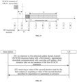
- PUSCH resource A is used by the UE to transmit uplink URLLC service data, and there is a DCI monitoring occasion 1 between the end moment of PUSCH resource A and a start moment of the measurement gap.
- the second duration T1 is needed by the base station to demodulate the URLLC service data.
- the base station demodulation fails, since the start moment of the DCI monitoring occasion 1 is earlier than the end moment of the second duration T1, the base station has been unable to send the UL grant for scheduling retransmission data at the DCI monitoring occasion 1.
- the base station sends an UL grant for scheduling retransmission data at the first DCI monitoring occasion after T1 (that is, DCI monitoring occasion 2).
- the base station From the end moment of PUSCH resource A to the end moment of DCI monitoring occasion 2, that is, within the second duration from the end moment of PUSCH resource A, the base station maintains downlink communication with the UE in the serving cell, so that the UE may receive the UL grant for retransmitted data at the DCI monitoring occasion 2, and the retransmitted data may be transmitted through the PUSCH resources.
- the data transmission method may further include the following step at 202.
- a value of the second duration sent by the base station is received, or a value of the second duration specified by negotiation or agreement in advance is acquired.
- the base station may configure the second duration for the UE through a high-layer signaling or the like.
- the second duration may be configured through a radio resource control (RRC) signaling.
- RRC radio resource control
- the indication information for indicating the second duration may be set in the RRC signaling by adding RRC parameters or the like.
- the base station and the UE may also negotiate in advance or determine the second duration according to a communication protocol or the like.
- the step at 201 may include one of:
- the UE maintains downlink communication with the serving cell, so that the base station has enough time to perform data demodulation, and sends the UL grant for scheduling retransmission data at the first DCI monitoring occasion after the demodulation is completed.
- the base station When a time interval from the end moment of the first PUSCH resources to any DCI monitoring occasion within the first time interval is less than the second duration, the base station has not completed data demodulation when a DCI monitoring occasion within the first time interval occurs, and it is not possible to send the UL grant for scheduling retransmission data at the DCI monitoring occasion within the first time interval. Therefore, within the first duration after the end moment of the first PUSCH resources, the UE maintains downlink communication with the serving cell, so that the base station has enough time to perform data demodulation, and sends the UL grant for scheduling retransmission data at the first DCI monitoring occasion after the demodulation is completed.
- the base station may send the UL grant for scheduling retransmission data at the DCI monitoring occasion without being affected by the measurement gap; on the other hand, the base station may send the UL grant for scheduling retransmission data at the first DCI monitoring occasion after demodulation is completed.
- the transmission efficiency is improved and the delay is reduced.
- the first PUSCH resources include: first PUSCH resources of newly transmitted data that is scheduled by a UL grant and is monitored at a DCI monitoring occasion; or first PUSCH resources of retransmission data that is scheduled by a UL grant and is monitored at a DCI monitoring occasion.
- the first PUSCH resources may be used to transmit the newly transmitted data or retransmitted data.
- the newly transmitted data or the retransmitted data may be the data scheduled by the UL grant within the DCI monitoring occasion.
- the base station may send the UL grant for scheduling retransmission data at the DCI monitoring occasion, without being affected by the measurement gap, thus reducing the data transmission delay.
- the data transmission method may further include: in response that the end moment of the predetermined DCI monitoring occasion is within the measurement gap and the end moment of the predetermined DCI monitoring occasion has not yet reached the end moment of the measurement gap, performing inter-frequency signal measurement between the end moment of the predetermined DCI monitoring occasion and the end moment of the measurement gap.
- the end moment of the DCI monitoring occasion 2 is t1
- the end moment of the measurement gap is t2, where t1 is within the measurement gap, and t1 to t2 is still in the measurement gap. Therefore, the UE may perform inter-frequency signal measurement between t1 and t2.
- the base station may interrupt the downlink communication with the UE in the serving cell between t1 and t2.
- the inter-frequency signal measurement may be performed on remaining time of the measurement gap, thus improving the utilization rate of the remaining time of the measurement gap.
- performing inter-frequency signal measurement between the end moment of the predetermined DCI monitoring occasion and the end moment of the measurement gap includes: in response to a time difference between the end moment of the predetermined DCI monitoring occasion and the end moment of the measurement gap being greater than a third duration, performing inter-frequency signal measurement between the end moment of the predetermined DCI monitoring occasion and the end moment of the measurement gap.
- the UE receiver needs certain radio frequency switching time when switching between the signal frequency point of the serving cell and the signal frequency point of the inter-frequency cell, which is a duration for which one frequency point switching is performed by the UE. Therefore, when the time difference between the end moment of the predetermined DCI monitoring occasion and the end moment of the measurement gap is less than twice the inter-frequency radio frequency switching time, the UE cannot switch back to the frequency point of the serving cell in time after the end moment of the measurement gap. That is, the UE cannot switch back to the serving cell in time for communication, thus causing useless radio frequency switching operations and even delaying downlink communication in the serving cell. Therefore, in order to avoid the above situations as much as possible, the base station may configure a third duration at least based on the radio frequency switching time. The third duration may be greater than or equal to twice the inter-frequency radio frequency switching time.
- the base station may configure the duration threshold based on factors other than the radio frequency switching time of the UE.
- the other factors include: a resource configuration state of the system, a global configuration of the base station and/or a channel quality, and the like.
- Enabling the third duration to be greater than or equal to twice the inter-frequency radio frequency switching time provides a basis for evaluating whether the UE may perform inter-frequency radio frequency switching for two times. On the one hand, the remaining period of the measurement gap may be effectively used for inter-frequency signal measurement, and on the other hand, the situation that the UE cannot be switched back to the serving cell in time may be reduced, thus reducing the invalid inter-frequency radio frequency switching.
- the duration from t1 to t2 is longer than the second duration T1.
- the UE may switch to the serving cell frequency for downlink communication starting from the time point t2 since the UE needs to perform radio frequency switching for two times, considering the time occupied by the inter-frequency signal measurement and the inter-frequency radio frequency switching duration of the UE. Therefore, the UE may perform inter-frequency signal measurement during the duration from t1 to t2, and the base station interrupts downlink communication with UE in the serving cell.
- the inter-frequency signal measurement may be performed on the remaining time of the measurement gap, thus improving the utilization rate of the remaining time of the measurement gap.
- the data transmission method may further include: in response to determining that the time difference between the end moment of the predetermined DCI monitoring occasion and the end moment of the measurement gap is less than or equal to the third duration, maintaining downlink communication with the serving cell between the end moment of the predetermined DCI monitoring occasion and the end moment of the measurement gap.
- the UE When the time difference between the end moment of the predetermined DCI monitoring occasion and the end moment of the measurement gap is less than or equal to the third duration, the UE cannot switch back to the frequency point of the serving cell in time after the end of the measurement gap, that is, the UE cannot switch back to the serving cell in time for communication, thus causing useless radio frequency switching operations and even delaying downlink communication in the serving cell.
- the UE may maintain downlink communication with the serving cell.
- the third duration may be set by the base station through a high-layer signaling.
- the duration from t1 to t2 is less than or equal to the third duration T2.
- the UE since the UE needs to perform radio frequency switching for two times, considering the time occupied by the inter-frequency signal measurement and the inter-frequency radio frequency switching duration of the UE, it may be determined that the UE cannot switch to the frequency point of the serving cell for downlink communication from the time point t2. Therefore, the UE may maintain receiving downlink information on the serving cell and do not perform inter-frequency signal measurement in the time period from t1 to t2.
- the third duration is greater than or equal to a duration of the UE performing inter-frequency radio frequency switching for two times.
- the UE switches receiving downlink data from the serving cell to performing inter-frequency signal measurement at frequency points of the inter-frequency cell, then switches to the downlink communication performed by the serving cell.
- the UE receiver needs to switch from signal frequency points of the serving cell to frequency points of the inter-frequency cell, and switch from the frequency points of the inter-frequency cell to the frequency points of the serving cell again.
- the UE needs to perform processing such as configuration on the receiver. Therefore, the third duration may be greater than or equal to twice the inter-frequency radio frequency switching duration of the UE.
- a data transmission method is provided according to an embodiment, which may be applied to a base station of wireless communication.
- the data transmission method may include the following step at 501.
- PUSCH physical uplink shared channel
- UE user equipment
- the first duration is a duration from the end moment of the first PUSCH resources to an end moment of a predetermined downlink control information (DCI) monitoring occasion.
- DCI downlink control information
- the predetermined DCI monitoring occasion is a first DCI monitoring occasion after a second duration gaped from the end moment of the first PUSCH resources.
- the PUSCH resources with the first priority may be used to transmit service data with a higher priority, such as downlink data service that requires a shorter delay, such as the URLLC service data and the like.
- the second priority has a lower priority than the first priority.
- the service data transmitted by the PUSCH resources with the second priority has a lower latency demand than the service data transmitted by the PUSCH resources with the first priority.
- the UE may monitor the UL grant sent by the base station in the serving cell through a physical downlink control channel (PDCCH) of a downlink at the DCI monitoring occasion.
- the UL grant may be used to schedule newly transmitted data or re-transmitted data.
- the base station may determine whether the data transmitted by using the PUSCH resources with the first priority is successfully received. If the reception fails, the base station may send the UL grant at the DCI monitoring occasion, so as to request the UE to retransmit the data through the UL grant.
- the measurement gap may be a periodic measurement period configured by the base station for the UE to perform inter-frequency signal measurement.
- the UE cannot measure inter-frequency signals in the inter-frequency cell and perform data transmission in the serving cell at the same time.
- normal transmission and reception of data services between the UE and the serving cell may be interrupted.
- the inter-frequency signal may be a signal different from the center frequency of the serving cell where the UE is currently located, may also be a signal from an inter-frequency cell at other band width parts (BWPs) that are different from the currently occupied BWP of the UE, etc., and may also be a signal from an inter-frequency cell with a different center frequency or a different sub-carrier space (SCS) in SSB measurement.
- the inter-frequency signal measurement may be performing signal quality measurement on the inter-frequency signal or monitoring the inter-frequency signal.
- the predetermined DCI monitoring occasion may be a DCI monitoring occasion at which the base station may send an UL grant for scheduling retransmission data.
- the UE may set that the inter-frequency signal measurement is not performed between the end moment of the first PUSCH resources and the end moment of the predetermined DCI monitoring occasion. That is, the inter-frequency signal measurement is not performed within the first duration after the end moment of the first PUSCH resources and the downlink communication with the serving cell is maintained for the first duration.
- the first PUSCH resources may be located outside the measurement gap or within the measurement gap in a time domain.
- the UE maintains downlink communication with the serving cell and no longer switches to the inter-frequency cell.
- the UE may receive a downlink signal sent by the serving cell to the UE through the downlink, or may monitor a downlink signal from the serving cell on the downlink, etc.
- the downlink signal includes, but is not limited to, control instructions and downlink data sent by the serving cell to the UE.
- the base station may send the UL grant for requesting retransmission data through the downlink without being affected by the measurement gap, and the UE may receive the UL grant for requesting the retransmission data, which further reduces the delay of data transmission.
- the base station may maintain downlink communication with the UE in the serving cell within the first duration after the end moment of the first PUSCH resources. In this way, when the base station determines that receiving the data transmitted by using the PUSCH resources with the first priority fails, the base station may send the UL grant for scheduling retransmission data at the predetermined DCI monitoring occasion, and the UE may retransmit the data that the base station fails to receive.
- the second duration may be a duration needed by the base station to determine whether the data transmitted by using the PUSCH resources with the first priority is successfully received.
- the base station determines whether the data is successfully received within the second duration, and when the reception fails, the base station sends the UL grant for scheduling retransmission data at the first DCI monitoring occasion after the second duration ends.
- the UE may monitor whether there is an UL grant for scheduling retransmission data at the first DCI monitoring occasion after the second duration ends, and may retransmit the data by using the PUSCH resources. In this way, the UL grant for scheduling retransmission data is sent at the first DCI monitoring occasion after it is determined that the retransmission is needed, which may reduce the delay of uplink data and meet the demand for low-latency data transmission.
- the UE may receive a transmission request of the base station for the uplink data by using the PUSCH resources with the first priority within the first duration, without being affected by the measurement gap, so as to reduce the possibility of failing to receive the transmission request due to the inter-frequency signal measurement during the measurement gap, reduce the delay of uplink data by using the PUSCH resources with the first priority for uplink data, and meet the demand for low-latency service transmission.
- the second duration is greater than or equal to a duration for which the base station demodulates data transmitted by the first PUSCH resources.
- the second duration may be the duration needed by the base station to demodulate the data transmitted by using the PUSCH resources with the first priority.
- the base station determines whether the data is successfully demodulated within the second duration, and when the demodulation fails, the base station sends an UL grant for scheduling retransmission data at the first DCI monitoring occasion after the second duration ends.
- the UE may monitor whether there is an UL grant for scheduling retransmitted data at the first DCI monitoring occasion after the second duration ends, and retransmit the data by using the PUSCH resources. In this way, the UL grant for scheduling the retransmission data is sent at the first DCI monitoring occasion after it is determined that retransmission is needed, which may reduce the delay of uplink data and meet the demand for low-latency data transmission.
- PUSCH resource A is used by the UE to transmit uplink URLLC service data, and there is a DCI monitoring occasion 1 between the end moment of PUSCH resource A and a start moment of the measurement gap.
- the second duration T1 is needed by the base station to demodulate the URLLC service data.
- the base station demodulation fails, since the start moment of the DCI monitoring occasion 1 is earlier than the end moment of the second duration T1, the base station has been unable to send the UL grant for scheduling retransmission data at the DCI monitoring occasion 1.
- the base station sends an UL grant for scheduling retransmission data at the first DCI monitoring occasion after T1 (that is, DCI monitoring occasion 2).
- the base station From the end moment of PUSCH resource A to the end moment of DCI monitoring occasion 2, that is, within the second duration from the end moment of PUSCH resource A, the base station maintains downlink communication with the UE in the serving cell, so that the UE may receive the UL grant for retransmitted data at the DCI monitoring occasion 2, and the retransmitted data may be transmitted through the PUSCH resources.
- the data transmission method may further include the following step at 502.
- a value of the second duration is sent to the UE; or a value of the second duration specified by negotiation or agreement in advance is acquired.
- the base station may configure the second duration for the UE through a high-layer signaling or the like.
- the second duration may be configured through a radio resource control (RRC) signaling.
- RRC radio resource control
- the indication information for indicating the second duration may be set in the RRC signaling by adding RRC parameters or the like.
- the base station and the UE may also negotiate in advance or determine the second duration according to a communication protocol or the like.
- the step at 501 may include one of:
- the base station may send the UL grant for scheduling retransmission data at the DCI monitoring occasion without being affected by the measurement gap; on the other hand, the base station may send the UL grant for scheduling retransmission data at the first DCI monitoring occasion after demodulation is completed.
- the transmission efficiency is improved and the delay is reduced.
- the first PUSCH resources may be used to transmit the newly transmitted data or retransmitted data.
- the newly transmitted data or the retransmitted data may be the data scheduled by the UL grant within the DCI monitoring occasion.
- the base station may send the UL grant for scheduling retransmission data at the DCI monitoring occasion, without being affected by the measurement gap, thus reducing the data transmission delay.
- the data transmission method may further include: in response that the end moment of the predetermined DCI monitoring occasion is within the measurement gap and the end moment of the predetermined DCI monitoring occasion has not yet reached the end moment of the measurement gap, interrupting downlink communication with the UE in the serving cell between the end moment of the predetermined DCI monitoring occasion and the end moment of the measurement gap.
- the end moment of the DCI monitoring occasion 2 is t1
- the end moment of the measurement gap is t2, where t1 is within the measurement gap, and t1 to t2 is still in the measurement gap. Therefore, the UE may perform inter-frequency signal measurement between t1 and t2.
- the base station may interrupt the downlink communication with the UE in the serving cell between t1 and t2.
- the inter-frequency signal measurement may be performed on remaining time of the measurement gap, thus improving the utilization rate of the remaining time of the measurement gap.
- the UE receiver needs certain radio frequency switching time when switching between the signal frequency point of the serving cell and the signal frequency point of the inter-frequency cell, which is a duration for which one frequency point switching is performed by the UE. Therefore, when the time difference between the end moment of the predetermined DCI monitoring occasion and the end moment of the measurement gap is less than twice the inter-frequency radio frequency switching time, the UE cannot switch back to the frequency point of the serving cell in time after the end moment of the measurement gap. That is, the UE cannot switch back to the serving cell in time for communication, thus causing useless radio frequency switching operations and even delaying downlink communication in the serving cell. Therefore, in order to avoid the above situations as much as possible, the base station may configure a third duration at least based on the radio frequency switching time.
- the third duration may be greater than or equal to twice the inter-frequency radio frequency switching time.
- the base station may configure the duration threshold based on factors other than the radio frequency switching time of the UE.
- the other factors include: a resource configuration state of the system, a global configuration of the base station and/or a channel quality, and the like. Enabling the third duration to be greater than or equal to twice the inter-frequency radio frequency switching time provides a basis for evaluating whether the UE may perform inter-frequency radio frequency switching for two times. On the one hand, the remaining period of the measurement gap may be effectively used for inter-frequency signal measurement, and on the other hand, the situation that the UE cannot be switched back to the serving cell in time may be reduced, thus reducing the invalid inter-frequency radio frequency switching.
- the duration from t1 to t2 is longer than the second duration T1.
- the UE may switch to the serving cell frequency for downlink communication starting from the time point t2 since the UE needs to perform radio frequency switching for two times, considering the time occupied by the inter-frequency signal measurement and the inter-frequency radio frequency switching duration of the UE. Therefore, the UE may perform inter-frequency signal measurement during the duration from t1 to t2, and the base station interrupts downlink communication with UE in the serving cell.
- the inter-frequency signal measurement may be performed on the remaining time of the measurement gap, thus improving the utilization rate of the remaining time of the measurement gap.
- the data transmission method may further include: in response to the time difference between the end moment of the predetermined DCI monitoring occasion and the end moment of the measurement gap being less than or equal to the third duration, maintaining downlink communication with the UE in the serving cell between the end moment of the predetermined DCI monitoring occasion and the end moment of the measurement gap.
- the UE When the time difference between the end moment of the predetermined DCI monitoring occasion and the end moment of the measurement gap is less than or equal to the third duration, the UE cannot switch back to the frequency point of the serving cell in time after the end of the measurement gap, that is, the UE cannot switch back to the serving cell in time for communication, thus causing useless radio frequency switching operations and even delaying downlink communication in the serving cell.
- the UE may maintain downlink communication with the serving cell.
- the third duration may be set by the base station through a high-layer signaling.
- the duration from t1 to t2 is less than or equal to the third duration T2.
- the UE since the UE needs to perform radio frequency switching for two times, considering the time occupied by the inter-frequency signal measurement and the inter-frequency radio frequency switching duration of the UE, it may be determined that the UE cannot switch to the frequency point of the serving cell for downlink communication from the time point t2. Therefore, the UE may maintain receiving downlink information on the serving cell and do not perform inter-frequency signal measurement in the time period from t1 to t2.
- the third duration is greater than or equal to a duration of the UE performing inter-frequency radio frequency switching for two times.
- the UE switches receiving downlink data from the serving cell to performing inter-frequency signal measurement at frequency points of the inter-frequency cell, then switches to the downlink communication performed by the serving cell.
- the UE receiver needs to switch from signal frequency points of the serving cell to frequency points of the inter-frequency cell, and switch from the frequency points of the inter-frequency cell to the frequency points of the serving cell again.
- the UE needs to perform processing such as configuration on the receiver. Therefore, the third duration may be greater than or equal to twice the inter-frequency radio frequency switching duration of the UE.
- a method for determining whether a user equipment (UE) may enter a measurement gap is provided. Since processing the SSB measurement timing configuration (SMTC) in the solution is the same as processing the measurement gap, the measurement gap may be used to describe the solution in the following.
- SSB measurement timing configuration SMTC
- the UE may not be able to enter the measurement gap according to a time position of the measurement gap configured by the RRC.
- the UE may enter the measurement gap at a DCI monitoring occasion which is located after the duration T1 from the end moment of the PUSCH resources, if the DCI monitoring occasion is still in the measurement gap configured by the RRC at this time.
- the above method may prevent the UE from entering the measurement gap when the base station has not finished demodulating the URLLC service data transmitted by using the PUSCH resources. After the base station has finished demodulation of the URLLC service data transmitted by using the PUSCH resources and after the DCI monitoring occasion is encountered, the UE may enter the measurement gap. In this way, it may ensure that the base station has the opportunity of scheduling the UE to retransmit the URLLC service data.
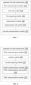
- FIG. 7 is a structural schematic diagram of a data transmission apparatus 100 according to an embodiment of the invention. As shown in FIG. 7 , the apparatus 100 includes: a communication module 110.
- the first communication module 110 is configured to, in response to first physical uplink shared channel (PUSCH) resources being with a first priority, maintain downlink communication with a serving cell within a first duration after an end moment of the first PUSCH resources.
- PUSCH physical uplink shared channel
- the first duration is a duration from the end moment of the first PUSCH resources to an end moment of a predetermined downlink control information (DCI) monitoring occasion.
- DCI downlink control information
- the predetermined DCI monitoring occasion is a first DCI monitoring occasion after a second duration gaped from the end moment of the first PUSCH resources.
- the second duration is greater than or equal to a duration for which a base station demodulates data transmitted by the first PUSCH resources.
- the apparatus 100 further includes: a receiving module 120, configured to receive a value of the second duration sent by a base station; or a first acquiring module 130, configured to acquire a value of the second duration specified by negotiation or agreement in advance.
- the first PUSCH resources include: first PUSCH resources of newly transmitted data that is scheduled by an uplink (UL) grant and is monitored at a DCI monitoring occasion; or first PUSCH resources of retransmission data that is scheduled by a UL grant and is monitored at a DCI monitoring occasion.
- the apparatus 100 further includes: a measurement module 140.
- the measurement module 140 is configured to in response that the end moment of the predetermined DCI monitoring occasion is within the measurement gap and has not yet reached the end moment of the measurement gap, perform inter-frequency signal measurement between the end moment of the predetermined DCI monitoring occasion and the end moment of the measurement gap.
- the measurement module 140 includes: a measurement sub-module 141.
- the measurement sub-module 141 is configured to perform inter-frequency signal measurement between the end moment of the predetermined DCI monitoring occasion and the end moment of the measurement gap in response to a time difference between the end moment of the predetermined DCI monitoring occasion and the end moment of the measurement gap being greater than a third duration.
- the apparatus 100 further includes: a second communication module 150.
- the second communication module 150 is configured to maintain downlink communication with the serving cell between the end moment of the predetermined DCI monitoring occasion and the end moment of the measurement gap, in response to determining that a time difference between the end moment of the predetermined DCI monitoring occasion and the end moment of the measurement gap is less than or equal to a third duration.
- the third duration is greater than or equal to a duration of the UE performing inter-frequency radio frequency switching for two times.
- FIG. 8 is a structural schematic diagram of a data transmission apparatus 200 according to an embodiment of the invention. As shown in FIG. 8 , the apparatus 200 includes: a third communication module 210.
- the third communication module 210 is configured to, in response to first physical uplink shared channel (PUSCH) resources being with a first priority, maintain downlink communication with a user equipment (UE) in a serving cell within a first duration after an end moment of the first PUSCH resources.
- PUSCH physical uplink shared channel
- UE user equipment
- the first duration is a duration from the end moment of the first PUSCH resources to an end moment of a predetermined downlink control information (DCI) monitoring occasion.
- DCI downlink control information
- the predetermined DCI monitoring occasion is a first DCI monitoring occasion after a second duration gaped from the end moment of the first PUSCH resources.
- the second duration is greater than or equal to a duration for which a base station demodulates data transmitted by the first PUSCH resources.
- the apparatus 200 further includes: a sending module 220, configured to send a value of the second duration to the UE; or a second acquiring module 230, configured to acquire a value of the second duration specified by negotiation or agreement in advance.
- the first PUSCH resources include: first PUSCH resources of newly transmitted data that is scheduled by an uplink (UL) grant sent at a DCI monitoring occasion; or first PUSCH resources of retransmission data that is scheduled by the UL grant sent at the DCI monitoring occasion.
- UL uplink
- the apparatus 200 further includes: a fourth communication module 240.
- the fourth communication module 240 is configured to in response that the end moment of the predetermined DCI monitoring occasion is within the measurement gap and has not yet reached the end moment of the measurement gap, interrupt the downlink communication with the UE in the serving cell between the end moment of the predetermined DCI monitoring occasion and the end moment of the measurement gap.
- the fourth communication module 240 includes: a fifth communication sub-module 241.
- the fifth communication sub-module 241 is configured to interrupt the downlink communication with the UE in the serving cell between the end moment of the predetermined DCI monitoring occasion and the end moment of the measurement gap, in response to a time difference between the end moment of the predetermined DCI monitoring occasion and the end moment of the measurement gap being greater than a third duration.
- the apparatus 100 further includes: a fifth communication module 250.
- the fifth communication module 250 is configured to maintain downlink communication with the UE in the serving cell between the end moment of the predetermined DCI monitoring occasion and the end moment of the measurement gap, in response that a time difference between the end moment of the predetermined DCI monitoring occasion and the end moment of the measurement gap is less than or equal to a third duration.
- the third duration is greater than or equal to a duration of the UE performing inter-frequency radio frequency switching for two times.
- the first communication module 110, the receiving module 120, the first obtaining module 130, the measurement module 140, the second communication module 150, the third communication module 210, the sending module 220, the second acquiring module 230, the fourth communication module 240 and the fifth communication module 250 and the like may be implemented by one or more central processing units (CPUs), graphics processing units (GPUs), baseband processors (BPs), application specific integrated circuits (ASICs), digital signal processors (DSPs), programmable logic devices (PLDs), complex programmable logic devices (CPLDs), field-programmable gate arrays (FPGAs), general-purpose processors, controllers, micro controller units (MCUs,), microprocessors, or other electronic components, for executing the aforementioned methods.
- CPUs central processing units
- GPUs graphics processing units
- BPs baseband processors
- ASICs application specific integrated circuits
- DSPs digital signal processors
- PLDs programmable logic devices
- CPLDs complex programmable logic devices
- FPGAs
- FIG. 9 is a block diagram of a device 3000 for data transmission according to an embodiment.
- the device 3000 may be a mobile phone, a computer, a digital broadcast terminal, a messaging device, a game console, a tablet device, a medical device, a fitness device, a personal digital assistant, or the like.
- the device 3000 may include one or more of the following components: a processing component 3002, a memory 3004, a power component 3006, a multimedia component 3008, an audio component 3010, an input/output (I/O) interface 3012, a sensor component 3014, and a communication component 3016.
- a processing component 3002 a memory 3004, a power component 3006, a multimedia component 3008, an audio component 3010, an input/output (I/O) interface 3012, a sensor component 3014, and a communication component 3016.
- the processing component 3002 generally controls overall operations of the device 3000, such as the operations associated with display, phone calls, data communications, camera operations, and recording operations.
- the processing component 3002 may include one or more processors 3020 to execute instructions to perform all or some of the steps of the methods described above.
- the processing component 3002 may include one or more modules that facilitate interactions between the processing component 3002 and other components.
- the processing component 3002 may include a multimedia module to facilitate interactions between the multimedia component 3008 and the processing component 3002.
- the memory 3004 is configured to store various types of data to support operation of the device 3000. Examples of such data include instructions for any application or method operating on the device 3000, contact data, phonebook data, messages, pictures, videos, and the like.
- the memory 3004 may be implemented by any type of volatile or nonvolatile storage device or their combination, such as a static random-access memory (SRAM), an electrically-erasable programmable read only memory (EEPROM), an erasable programmable read only memory (EPROM), a programmable read only memory (PROM), a read only memory (ROM), a magnetic memory, a flash memory, a magnetic or optical disk.
- SRAM static random-access memory
- EEPROM electrically-erasable programmable read only memory
- EPROM erasable programmable read only memory
- PROM programmable read only memory
- ROM read only memory
- magnetic memory a magnetic memory
- flash memory a flash memory
- magnetic or optical disk a magnetic or optical disk.
- the power component 3006 provides power to various components of the device 3000.
- the power component 3006 may include a power management system, one or more power sources, and any other components associated with the generation, management, and distribution of power in the device 3000.
- the multimedia component 3008 includes a screen providing an output interface between the device 3000 and the user.
- the screen may include a liquid crystal display (LCD) and a touch panel (TP). If the screen includes the touch panel, the screen may be implemented as a touch screen to receive input signals from the user.
- the touch panel includes one or more touch sensors to sense touches, swipes, and gestures on the touch panel. The touch sensors may not only sense a boundary of a touch or swipe action, but also sense a duration and a pressure associated with the touch or swipe action.
- the multimedia component 3008 includes a front-facing camera and/or a rear-facing camera.
- the front-facing camera and/or the rear-facing camera can receive external multimedia data.
- Each front-facing camera and rear-facing camera may be a fixed optical lens system or has focal length and optical zoom capability.
- the audio component 3010 is configured to output and/or input audio signals.
- the audio component 3010 includes a microphone (MIC for short) that is configured to receive external audio signals when the device 3000 is in an operating mode, such as a call mode, a recording mode, and a voice recognition mode.
- the received audio signal may be further stored in the memory 3004 or transmitted via the communication component 3016.
- the audio component 3010 also includes a speaker for outputting audio signals.
- the I/O interface 3012 provides an interface between the processing component 3002 and peripheral interface modules, such as a keyboard, a click wheel, buttons, and the like.
- the buttons may include, but are not limited to, a home button, a volume button, a starting button, and a locking button.
- the sensor component 3014 includes one or more sensors to provide status assessments of various aspects of the device 3000. For instance, the sensor component 3014 may detect an open/closed status of the device 3000, relative positioning of components, e.g., the display and the keypad, of the device 3000, a change in position of the device 3000 or a component of the device 3000, a presence or absence of user contact with the device 3000, an orientation or an acceleration/deceleration of the device 3000, and a change in temperature of the device 3000.
- the sensor component 3014 may include a proximity sensor configured to detect the presence of nearby objects without any physical contact.
- the sensor component 3014 may also include a light sensor, such as a complementary metal oxide semiconductor (CMOS) or a charge-coupled device (CCD) image sensor, for use in imaging applications.
- CMOS complementary metal oxide semiconductor
- CCD charge-coupled device
- the sensor component 3014 may also include an accelerometer sensor, a gyroscope sensor, a magnetic sensor, a pressure sensor, or a temperature sensor.
- the communication component 3016 is configured to facilitate communication, wired or wirelessly, between the device 3000 and other devices.
- the device 3000 can access a wireless network based on a communication standard, such as WiFi, 2G, or 3G, or their combination.
- the communication component 3016 receives a broadcast signal or broadcast associated information from an external broadcast management system via a broadcast channel.
- the communication component 3016 further includes a near field communication (NFC) module to facilitate short-range communications.
- the NFC module may be implemented based on a radio frequency identification (RFID) technology, an infrared data association (IrDA) technology, an ultra-wide band (UWB) technology, a Bluetooth (BT) technology, and other technologies.
- RFID radio frequency identification
- IrDA infrared data association
- UWB ultra-wide band
- BT Bluetooth
- the device 3000 may be implemented with one or more application specific integrated circuits (ASICs), digital signal processors (DSPs), digital signal processing devices (DSPDs), programmable logic devices (PLDs), field programmable gate arrays (FPGAs), controllers, micro-controllers, microprocessors, or other electronic components, for performing the above described method.
- ASICs application specific integrated circuits
- DSPs digital signal processors
- DSPDs digital signal processing devices
- PLDs programmable logic devices
- FPGAs field programmable gate arrays
- controllers micro-controllers, microprocessors, or other electronic components, for performing the above described method.
- non-transitory computer readable storage medium including instructions, such as included in the memory 3004, executable by the processor 3020 in the device 3000, for performing the above method.
- the non-transitory computer readable storage medium may be a ROM, a random access memory (RAM), a CD-ROM, a magnetic tape, a floppy disc, an optical data storage device, and the like.
Landscapes
- Engineering & Computer Science (AREA)
- Signal Processing (AREA)
- Computer Networks & Wireless Communication (AREA)
- Mobile Radio Communication Systems (AREA)
Claims (15)
- Procédé destiné à la transmission de données, mis en oeuvre par un équipement utilisateur, UE (11), comprenant :en réponse à des premières ressources de canal partagé de liaison montante physique, PUSCH, (A) étant avec une première priorité, le maintien (201) d'une communication en liaison descendante avec une cellule de desserte au cours d'une première durée après un moment de fin des premières ressources PUSCH ;le procédé caractérisé en ce quela première durée est une durée (T3) à partir du moment de fin des premières ressources PUSCH jusqu'à un moment de fin (t1) d'une occasion de surveillance d'informations de commande de liaison descendante, DCI, prédéterminée, etl'occasion de surveillance de DCI prédéterminée est une première occasion de surveillance de DCI après une deuxième durée (T1) s'étendant à un intervalle du moment de fin des premières ressources PUSCH.
- Procédé selon la revendication 1, dans lequel la deuxième durée est supérieure ou égale à une durée pendant laquelle une station de base (12) démodule des données transmises par les premières ressources PUSCH.
- Procédé selon la revendication 1, comprenant en outre l'une parmi :la réception (202) d'une valeur de la deuxième durée envoyée par une station de base ; etl'acquisition (202) d'une valeur de la deuxième durée spécifiée par négociation ou accord préalable.
- Procédé selon la revendication 1, dans lequel les premières ressources PUSCH comprennent l'une parmi :des premières ressources PUSCH de données nouvellement transmises qui sont planifiées par une autorisation de liaison montante, UL, et sont surveillées lors d'une occasion de surveillance de DCI ; etdes premières ressources PUSCH de données de retransmission qui sont planifiées par une autorisation UL et sont surveillées lors d'une occasion de surveillance de DCI.
- Procédé selon la revendication 1, comprenant en outre :
en réponse au fait que le moment de fin (t1) de l'occasion de surveillance de DCI prédéterminée se trouve au sein d'un intervalle de mesure et n'a pas encore atteint un moment de fin (t2) de l'intervalle de mesure, la mise en oeuvre d'une mesure de signal inter-fréquence entre le moment de fin de l'occasion de surveillance de DCI prédéterminée et le moment de fin de l'intervalle de mesure. - Procédé selon la revendication 5, dans lequel la mise en oeuvre d'une mesure de signal inter-fréquence entre le moment de fin de l'occasion de surveillance de DCI prédéterminée et le moment de fin de l'intervalle de mesure, comprend :en réponse à une différence de temps entre le moment de fin (t1) de l'occasion de surveillance de DCI prédéterminée et le moment de fin (t2) de l'intervalle de mesure étant supérieure à une troisième durée (T2), la mise en oeuvre d'une mesure de signal inter-fréquence entre le moment de fin de l'occasion de surveillance de DCI prédéterminée et le moment de fin de l'intervalle de mesure ; oule procédé comprend en outre : en réponse à la détermination qu'une différence de temps entre le moment de fin (t1) de l'occasion de surveillance de DCI prédéterminée et le moment de fin (t2) de l'intervalle de mesure est inférieure ou égale à une troisième durée (T3), le maintien d'une communication en liaison descendante avec la cellule de desserte entre le moment de fin de l'occasion de surveillance de DCI prédéterminée et le moment de fin de l'intervalle de mesure.
- Procédé selon la revendication 6, dans lequel
la troisième durée est supérieure ou égale à une durée de l'UE mettant en oeuvre une commutation de radiofréquence inter-fréquence deux fois. - Procédé destiné à la transmission de données, mis en oeuvre par une station de base (12), comprenant :en réponse à des premières ressources de canal partagé de liaison montante physique, PUSCH (A) étant avec une première priorité, le maintien (201, 501) d'une communication en liaison descendante avec un équipement utilisateur, UE (11) dans une cellule de desserte au cours d'une première durée après un moment de fin des premières ressources PUSCH ;le procédé caractérisé en ce quela première durée est une durée (T3) à partir du moment de fin (t1) des premières ressources PUSCH jusqu'à un moment de fin (t2) d'une occasion de surveillance d'informations de commande de liaison descendante (DCI) prédéterminée, etl'occasion de surveillance de DCI prédéterminée est une première occasion de surveillance de DCI après une deuxième durée (T1) s'étendant à un intervalle du moment de fin des premières ressources PUSCH.
- Procédé selon la revendication 8, dans lequel la deuxième durée est supérieure ou égale à une durée pendant laquelle la station de base démodule des données transmises par les premières ressources PUSCH.
- Procédé selon la revendication 8, comprenant en outre l'un parmi :l'envoi (502) d'une valeur de la deuxième durée à l'UE ; etl'acquisition (502) d'une valeur de la deuxième durée spécifiée par négociation ou accord préalable.
- Procédé selon la revendication 8, dans lequel les premières ressources PUSCH comprennent l'une parmi :des premières ressources PUSCH de données nouvellement transmises qui sont planifiées par une autorisation de liaison montante (UL) envoyée lors d'une occasion de surveillance de DCI ; etdes premières ressources PUSCH de données de retransmission qui sont planifiées par l'autorisation UL envoyée lors de l'occasion de surveillance de DCI.
- Procédé selon la revendication 8, comprenant en outre :
en réponse au fait que le moment de fin (t1) de l'occasion de surveillance de DCI prédéterminée se trouve au sein d'un intervalle de mesure et n'a pas encore atteint un moment de fin (t2) de l'intervalle de mesure, l'interruption de la communication en liaison descendante avec l'UE dans la cellule de desserte entre le moment de fin de l'occasion de surveillance de DCI prédéterminée et le moment de fin de l'intervalle de mesure. - Procédé selon la revendication 12, dans lequel l'interruption de la communication en liaison descendante avec l'UE dans la cellule de desserte entre le moment de fin de l'occasion de surveillance de DCI prédéterminée et le moment de fin de l'intervalle de mesure, comprend :en réponse à une différence de temps entre le moment de fin (t1) de l'occasion de surveillance de DCI prédéterminée et le moment de fin (t2) de l'intervalle de mesure étant supérieure à une troisième durée (T2), l'interruption de la communication en liaison descendante avec l'UE dans la cellule de desserte entre le moment de fin de l'occasion de surveillance de DCI prédéterminée et le moment de fin de l'intervalle de mesure ; oule procédé comprend en outre : en réponse à la détermination qu'une différence de temps entre le moment de fin (t1) de l'occasion de surveillance de DCI prédéterminée et le moment de fin (t2) de l'intervalle de mesure est inférieure ou égale à une troisième durée (T2), le maintien d'une communication en liaison descendante avec l'UE dans la cellule de desserte entre le moment de fin de l'occasion de surveillance de DCI prédéterminée et le moment de fin de l'intervalle de mesure.
- Dispositif de communication, comprenant : un processeur, un transcepteur, une mémoire et des programmes stockés sur la mémoire et exécutables par le processeur, dans lequel lorsque les programmes sont exécutés par le processeur, le procédé destiné à la transmission de données selon l'une quelconque des revendications 1 à 7 est effectué.
- Dispositif de communication, comprenant : un processeur, un transcepteur, une mémoire et des programmes stockés sur la mémoire et exécutables par le processeur, dans lequel lorsque les programmes sont exécutés par le processeur, le procédé destiné à la transmission de données selon l'une quelconque des revendications 8 à 13 est effectué.
Applications Claiming Priority (1)
| Application Number | Priority Date | Filing Date | Title |
|---|---|---|---|
| PCT/CN2020/076059 WO2021163969A1 (fr) | 2020-02-20 | 2020-02-20 | Procédé et appareil de transmission de données, et dispositif de communication |
Publications (3)
| Publication Number | Publication Date |
|---|---|
| EP4109986A1 EP4109986A1 (fr) | 2022-12-28 |
| EP4109986A4 EP4109986A4 (fr) | 2023-11-29 |
| EP4109986B1 true EP4109986B1 (fr) | 2024-11-06 |
Family
ID=77390334
Family Applications (1)
| Application Number | Title | Priority Date | Filing Date |
|---|---|---|---|
| EP20919564.3A Active EP4109986B1 (fr) | 2020-02-20 | 2020-02-20 | Procédé et appareil de transmission de données, et dispositif de communication |
Country Status (4)
| Country | Link |
|---|---|
| US (1) | US12342350B2 (fr) |
| EP (1) | EP4109986B1 (fr) |
| CN (1) | CN113545148B (fr) |
| WO (1) | WO2021163969A1 (fr) |
Families Citing this family (2)
| Publication number | Priority date | Publication date | Assignee | Title |
|---|---|---|---|---|
| KR20240039052A (ko) * | 2021-11-03 | 2024-03-26 | 엘지전자 주식회사 | 무선 통신 시스템에서 복제된 데이터 유닛을 측정 갭을 고려하여 전송하기 위한 방법 및 장치 |
| WO2024074002A1 (fr) * | 2023-02-17 | 2024-04-11 | Lenovo (Beijing) Limited | Procédé et appareil de prise en charge d'acquisition d'avance temporelle (ta) |
Family Cites Families (12)
| Publication number | Priority date | Publication date | Assignee | Title |
|---|---|---|---|---|
| CN101686551B (zh) * | 2008-09-22 | 2011-09-28 | 电信科学技术研究院 | 基于优先级管理的通信控制方法及装置 |
| WO2014161178A1 (fr) | 2013-04-03 | 2014-10-09 | 华为技术有限公司 | Procédé et dispositif pour mesurer une cellule inter-fréquence |
| WO2016165079A1 (fr) * | 2015-04-14 | 2016-10-20 | 华为技术有限公司 | Procédé, appareil et système de surveillance d'informations de commande de liaison descendante |
| CN112203260B (zh) * | 2016-11-03 | 2022-05-10 | 华为技术有限公司 | 数据传输方法及装置 |
| CN108282896B (zh) * | 2017-01-06 | 2019-08-30 | 电信科学技术研究院 | 一种上行数据重传方法及终端 |
| US10588042B2 (en) * | 2017-07-11 | 2020-03-10 | Qualcomm Incorporated | Transmission opportunities during measurement gaps |
| CN109842869B (zh) * | 2017-11-17 | 2025-03-07 | 北京三星通信技术研究有限公司 | 调度信息接收的方法及设备 |
| US11323989B2 (en) * | 2018-02-26 | 2022-05-03 | Huawei Technologies Co., Ltd. | Method and apparatus for bandwidth indication in unlicensed spectrum |
| WO2019204995A1 (fr) * | 2018-04-24 | 2019-10-31 | 北京小米移动软件有限公司 | Procédé et dispositif de transmission de demande de planification et procédé et dispositif d'attribution de ressources |
| WO2020032587A1 (fr) * | 2018-08-08 | 2020-02-13 | 엘지전자 주식회사 | Procédé d'émission ou de réception d'un canal partagé de liaison montante physique dans un système de communication sans fil et appareil correspondant |
| CN117202375A (zh) * | 2018-08-09 | 2023-12-08 | 北京三星通信技术研究有限公司 | 用于rrc空闲态上行传输的方法及设备 |
| CN115842607B (zh) * | 2018-11-02 | 2024-06-11 | 中兴通讯股份有限公司 | Harq-ack码本确定方法及装置、终端、存储介质 |
-
2020
- 2020-02-20 EP EP20919564.3A patent/EP4109986B1/fr active Active
- 2020-02-20 CN CN202080000329.1A patent/CN113545148B/zh active Active
- 2020-02-20 WO PCT/CN2020/076059 patent/WO2021163969A1/fr not_active Ceased
- 2020-02-20 US US17/800,194 patent/US12342350B2/en active Active
Also Published As
| Publication number | Publication date |
|---|---|
| CN113545148B (zh) | 2024-05-28 |
| CN113545148A (zh) | 2021-10-22 |
| US12342350B2 (en) | 2025-06-24 |
| EP4109986A4 (fr) | 2023-11-29 |
| US20230071861A1 (en) | 2023-03-09 |
| WO2021163969A1 (fr) | 2021-08-26 |
| EP4109986A1 (fr) | 2022-12-28 |
Similar Documents
| Publication | Publication Date | Title |
|---|---|---|
| EP4135367B1 (fr) | Procédé et dispositif de réglage d'heure d'activation et support d'enregistrement lisible par ordinateur | |
| EP4096279B1 (fr) | Procédé et appareil de transmission de données, dispositif de communication et support de stockage | |
| US12464532B2 (en) | Data transmission method and apparatus, and communication device | |
| US20240397532A1 (en) | Methods for determining cfr, and communication device and storage medium | |
| EP4117375B1 (fr) | Procédé et appareil d'accès à un réseau sans fil, dispositif de communication et support de stockage | |
| EP4149152A1 (fr) | Procédé et appareil de transmission d'informations, et dispositif de communication | |
| EP4290954B1 (fr) | Procédé et appareil de commutation de partie de bande passante, et dispositif de communication | |
| EP4221031B1 (fr) | Procédé et appareil de détermination d'un temps effectif, dispositif de communication et support de stockage | |
| US20230388876A1 (en) | Connection establishment method and apparatus, and communication device and storage medium | |
| US12317110B2 (en) | Channel measurement method and apparatus, and communication device | |
| WO2022040897A1 (fr) | Procédé et appareil de programmation de transmission, dispositif de communication et support de stockage | |
| CN111149388B (zh) | 通信处理方法、装置及计算机存储介质 | |
| US20230156703A1 (en) | DATA TRANSMISSION SCHEDULING METHOD AND DEVICE, AND STORAGE MEDIUM (as amended) | |
| EP4109986B1 (fr) | Procédé et appareil de transmission de données, et dispositif de communication | |
| US12581441B2 (en) | Communication processing method, apparatus, communication device, and storage medium | |
| US20240284354A1 (en) | Information transmission method and apparatus, and communication device and storage medium | |
| US20230262691A1 (en) | Uplink transmission sending method and apparatus, uplink transmission receiving method and apparatus, communication device, and medium | |
| US20250151120A1 (en) | Bandwidth part switching method and apparatus, communication device, and storage medium | |
| EP4057551B1 (fr) | Procédé et appareil de configuration d'informations de commande de liaison descendante et dispositif de communication et support de stockage | |
| US20250048482A1 (en) | Information processing method and apparatus, communication device and storage medium | |
| CN114788380A (zh) | 下行传输配置、接收方法及装置、通信设备及存储介质 | |
| EP4669015A1 (fr) | Procédé et appareil de transmission de données et support de stockage | |
| EP4622324A1 (fr) | Procédé et appareil de traitement après une défaillance de connexion, et dispositif terminal et dispositif côté réseau | |
| US12621111B2 (en) | Methods for determining effective time, and communication device | |
| US20240188013A1 (en) | Methods and devices for updating time offset value, and storage medium |
Legal Events
| Date | Code | Title | Description |
|---|---|---|---|
| STAA | Information on the status of an ep patent application or granted ep patent |
Free format text: STATUS: THE INTERNATIONAL PUBLICATION HAS BEEN MADE |
|
| PUAI | Public reference made under article 153(3) epc to a published international application that has entered the european phase |
Free format text: ORIGINAL CODE: 0009012 |
|
| STAA | Information on the status of an ep patent application or granted ep patent |
Free format text: STATUS: REQUEST FOR EXAMINATION WAS MADE |
|
| 17P | Request for examination filed |
Effective date: 20220919 |
|
| AK | Designated contracting states |
Kind code of ref document: A1 Designated state(s): AL AT BE BG CH CY CZ DE DK EE ES FI FR GB GR HR HU IE IS IT LI LT LU LV MC MK MT NL NO PL PT RO RS SE SI SK SM TR |
|
| DAV | Request for validation of the european patent (deleted) | ||
| DAX | Request for extension of the european patent (deleted) | ||
| REG | Reference to a national code |
Ref country code: DE Ref legal event code: R079 Free format text: PREVIOUS MAIN CLASS: H04W0072040000 Ipc: H04L0005000000 Ref document number: 602020041106 Country of ref document: DE |
|
| A4 | Supplementary search report drawn up and despatched |
Effective date: 20231030 |
|
| RIC1 | Information provided on ipc code assigned before grant |
Ipc: H04L 5/00 20060101AFI20231024BHEP |
|
| GRAP | Despatch of communication of intention to grant a patent |
Free format text: ORIGINAL CODE: EPIDOSNIGR1 |
|
| STAA | Information on the status of an ep patent application or granted ep patent |
Free format text: STATUS: GRANT OF PATENT IS INTENDED |
|
| RIC1 | Information provided on ipc code assigned before grant |
Ipc: H04L 5/00 20060101AFI20240628BHEP |
|
| INTG | Intention to grant announced |
Effective date: 20240730 |
|
| GRAS | Grant fee paid |
Free format text: ORIGINAL CODE: EPIDOSNIGR3 |
|
| GRAA | (expected) grant |
Free format text: ORIGINAL CODE: 0009210 |
|
| STAA | Information on the status of an ep patent application or granted ep patent |
Free format text: STATUS: THE PATENT HAS BEEN GRANTED |
|
| P01 | Opt-out of the competence of the unified patent court (upc) registered |
Free format text: CASE NUMBER: APP_49694/2024 Effective date: 20240902 |
|
| AK | Designated contracting states |
Kind code of ref document: B1 Designated state(s): AL AT BE BG CH CY CZ DE DK EE ES FI FR GB GR HR HU IE IS IT LI LT LU LV MC MK MT NL NO PL PT RO RS SE SI SK SM TR |
|
| REG | Reference to a national code |
Ref country code: GB Ref legal event code: FG4D |
|
| REG | Reference to a national code |
Ref country code: CH Ref legal event code: EP |
|
| REG | Reference to a national code |
Ref country code: DE Ref legal event code: R096 Ref document number: 602020041106 Country of ref document: DE |
|
| REG | Reference to a national code |
Ref country code: IE Ref legal event code: FG4D Ref country code: NL Ref legal event code: FP |
|
| REG | Reference to a national code |
Ref country code: LT Ref legal event code: MG9D |
|
| PG25 | Lapsed in a contracting state [announced via postgrant information from national office to epo] |
Ref country code: IS Free format text: LAPSE BECAUSE OF FAILURE TO SUBMIT A TRANSLATION OF THE DESCRIPTION OR TO PAY THE FEE WITHIN THE PRESCRIBED TIME-LIMIT Effective date: 20250306 Ref country code: HR Free format text: LAPSE BECAUSE OF FAILURE TO SUBMIT A TRANSLATION OF THE DESCRIPTION OR TO PAY THE FEE WITHIN THE PRESCRIBED TIME-LIMIT Effective date: 20241106 Ref country code: PT Free format text: LAPSE BECAUSE OF FAILURE TO SUBMIT A TRANSLATION OF THE DESCRIPTION OR TO PAY THE FEE WITHIN THE PRESCRIBED TIME-LIMIT Effective date: 20250306 |
|
| PG25 | Lapsed in a contracting state [announced via postgrant information from national office to epo] |
Ref country code: FI Free format text: LAPSE BECAUSE OF FAILURE TO SUBMIT A TRANSLATION OF THE DESCRIPTION OR TO PAY THE FEE WITHIN THE PRESCRIBED TIME-LIMIT Effective date: 20241106 |
|
| REG | Reference to a national code |
Ref country code: AT Ref legal event code: MK05 Ref document number: 1740573 Country of ref document: AT Kind code of ref document: T Effective date: 20241106 |
|
| PG25 | Lapsed in a contracting state [announced via postgrant information from national office to epo] |
Ref country code: BG Free format text: LAPSE BECAUSE OF FAILURE TO SUBMIT A TRANSLATION OF THE DESCRIPTION OR TO PAY THE FEE WITHIN THE PRESCRIBED TIME-LIMIT Effective date: 20241106 |
|
| PG25 | Lapsed in a contracting state [announced via postgrant information from national office to epo] |
Ref country code: ES Free format text: LAPSE BECAUSE OF FAILURE TO SUBMIT A TRANSLATION OF THE DESCRIPTION OR TO PAY THE FEE WITHIN THE PRESCRIBED TIME-LIMIT Effective date: 20241106 |
|
| PG25 | Lapsed in a contracting state [announced via postgrant information from national office to epo] |
Ref country code: NO Free format text: LAPSE BECAUSE OF FAILURE TO SUBMIT A TRANSLATION OF THE DESCRIPTION OR TO PAY THE FEE WITHIN THE PRESCRIBED TIME-LIMIT Effective date: 20250206 |
|
| PG25 | Lapsed in a contracting state [announced via postgrant information from national office to epo] |
Ref country code: AT Free format text: LAPSE BECAUSE OF FAILURE TO SUBMIT A TRANSLATION OF THE DESCRIPTION OR TO PAY THE FEE WITHIN THE PRESCRIBED TIME-LIMIT Effective date: 20241106 Ref country code: LV Free format text: LAPSE BECAUSE OF FAILURE TO SUBMIT A TRANSLATION OF THE DESCRIPTION OR TO PAY THE FEE WITHIN THE PRESCRIBED TIME-LIMIT Effective date: 20241106 Ref country code: GR Free format text: LAPSE BECAUSE OF FAILURE TO SUBMIT A TRANSLATION OF THE DESCRIPTION OR TO PAY THE FEE WITHIN THE PRESCRIBED TIME-LIMIT Effective date: 20250207 |
|
| PG25 | Lapsed in a contracting state [announced via postgrant information from national office to epo] |
Ref country code: PL Free format text: LAPSE BECAUSE OF FAILURE TO SUBMIT A TRANSLATION OF THE DESCRIPTION OR TO PAY THE FEE WITHIN THE PRESCRIBED TIME-LIMIT Effective date: 20241106 |
|
| PG25 | Lapsed in a contracting state [announced via postgrant information from national office to epo] |
Ref country code: RS Free format text: LAPSE BECAUSE OF FAILURE TO SUBMIT A TRANSLATION OF THE DESCRIPTION OR TO PAY THE FEE WITHIN THE PRESCRIBED TIME-LIMIT Effective date: 20250206 |
|
| PG25 | Lapsed in a contracting state [announced via postgrant information from national office to epo] |
Ref country code: SM Free format text: LAPSE BECAUSE OF FAILURE TO SUBMIT A TRANSLATION OF THE DESCRIPTION OR TO PAY THE FEE WITHIN THE PRESCRIBED TIME-LIMIT Effective date: 20241106 |
|
| PG25 | Lapsed in a contracting state [announced via postgrant information from national office to epo] |
Ref country code: DK Free format text: LAPSE BECAUSE OF FAILURE TO SUBMIT A TRANSLATION OF THE DESCRIPTION OR TO PAY THE FEE WITHIN THE PRESCRIBED TIME-LIMIT Effective date: 20241106 |
|
| PG25 | Lapsed in a contracting state [announced via postgrant information from national office to epo] |
Ref country code: EE Free format text: LAPSE BECAUSE OF FAILURE TO SUBMIT A TRANSLATION OF THE DESCRIPTION OR TO PAY THE FEE WITHIN THE PRESCRIBED TIME-LIMIT Effective date: 20241106 |
|
| PG25 | Lapsed in a contracting state [announced via postgrant information from national office to epo] |
Ref country code: RO Free format text: LAPSE BECAUSE OF FAILURE TO SUBMIT A TRANSLATION OF THE DESCRIPTION OR TO PAY THE FEE WITHIN THE PRESCRIBED TIME-LIMIT Effective date: 20241106 |
|
| PG25 | Lapsed in a contracting state [announced via postgrant information from national office to epo] |
Ref country code: SK Free format text: LAPSE BECAUSE OF FAILURE TO SUBMIT A TRANSLATION OF THE DESCRIPTION OR TO PAY THE FEE WITHIN THE PRESCRIBED TIME-LIMIT Effective date: 20241106 |
|
| PG25 | Lapsed in a contracting state [announced via postgrant information from national office to epo] |
Ref country code: CZ Free format text: LAPSE BECAUSE OF FAILURE TO SUBMIT A TRANSLATION OF THE DESCRIPTION OR TO PAY THE FEE WITHIN THE PRESCRIBED TIME-LIMIT Effective date: 20241106 |
|
| PG25 | Lapsed in a contracting state [announced via postgrant information from national office to epo] |
Ref country code: IT Free format text: LAPSE BECAUSE OF FAILURE TO SUBMIT A TRANSLATION OF THE DESCRIPTION OR TO PAY THE FEE WITHIN THE PRESCRIBED TIME-LIMIT Effective date: 20241106 |
|
| REG | Reference to a national code |
Ref country code: DE Ref legal event code: R097 Ref document number: 602020041106 Country of ref document: DE |
|
| REG | Reference to a national code |
Ref country code: DE Ref legal event code: R119 Ref document number: 602020041106 Country of ref document: DE |
|
| PG25 | Lapsed in a contracting state [announced via postgrant information from national office to epo] |
Ref country code: SE Free format text: LAPSE BECAUSE OF FAILURE TO SUBMIT A TRANSLATION OF THE DESCRIPTION OR TO PAY THE FEE WITHIN THE PRESCRIBED TIME-LIMIT Effective date: 20241106 |
|
| PLBE | No opposition filed within time limit |
Free format text: ORIGINAL CODE: 0009261 |
|
| STAA | Information on the status of an ep patent application or granted ep patent |
Free format text: STATUS: NO OPPOSITION FILED WITHIN TIME LIMIT |
|
| PG25 | Lapsed in a contracting state [announced via postgrant information from national office to epo] |
Ref country code: MC Free format text: LAPSE BECAUSE OF FAILURE TO SUBMIT A TRANSLATION OF THE DESCRIPTION OR TO PAY THE FEE WITHIN THE PRESCRIBED TIME-LIMIT Effective date: 20241106 |
|
| REG | Reference to a national code |
Ref country code: CH Ref legal event code: PL |
|
| 26N | No opposition filed |
Effective date: 20250807 |
|
| PG25 | Lapsed in a contracting state [announced via postgrant information from national office to epo] |
Ref country code: LU Free format text: LAPSE BECAUSE OF NON-PAYMENT OF DUE FEES Effective date: 20250220 |
|
| PG25 | Lapsed in a contracting state [announced via postgrant information from national office to epo] |
Ref country code: CH Free format text: LAPSE BECAUSE OF NON-PAYMENT OF DUE FEES Effective date: 20250228 |
|
| REG | Reference to a national code |
Ref country code: BE Ref legal event code: MM Effective date: 20250228 |
|
| PG25 | Lapsed in a contracting state [announced via postgrant information from national office to epo] |
Ref country code: DE Free format text: LAPSE BECAUSE OF NON-PAYMENT OF DUE FEES Effective date: 20250902 |
|
| PG25 | Lapsed in a contracting state [announced via postgrant information from national office to epo] |
Ref country code: BE Free format text: LAPSE BECAUSE OF NON-PAYMENT OF DUE FEES Effective date: 20250228 |
|
| PG25 | Lapsed in a contracting state [announced via postgrant information from national office to epo] |
Ref country code: IE Free format text: LAPSE BECAUSE OF NON-PAYMENT OF DUE FEES Effective date: 20250220 |
|
| PGFP | Annual fee paid to national office [announced via postgrant information from national office to epo] |
Ref country code: NL Payment date: 20260220 Year of fee payment: 7 |
|
| PGFP | Annual fee paid to national office [announced via postgrant information from national office to epo] |
Ref country code: GB Payment date: 20260224 Year of fee payment: 7 |
|
| PGFP | Annual fee paid to national office [announced via postgrant information from national office to epo] |
Ref country code: FR Payment date: 20260224 Year of fee payment: 7 |