EP4110423B1 - Kombination aus blutpumpe und oxygenatorsystem und zugehörige verfahren - Google Patents
Kombination aus blutpumpe und oxygenatorsystem und zugehörige verfahren Download PDFInfo
- Publication number
- EP4110423B1 EP4110423B1 EP21708954.9A EP21708954A EP4110423B1 EP 4110423 B1 EP4110423 B1 EP 4110423B1 EP 21708954 A EP21708954 A EP 21708954A EP 4110423 B1 EP4110423 B1 EP 4110423B1
- Authority
- EP
- European Patent Office
- Prior art keywords
- oxygenator
- blood
- blood pump
- pump
- manifold
- Prior art date
- Legal status (The legal status is an assumption and is not a legal conclusion. Google has not performed a legal analysis and makes no representation as to the accuracy of the status listed.)
- Active
Links
Images


Classifications
-
- A—HUMAN NECESSITIES
- A61—MEDICAL OR VETERINARY SCIENCE; HYGIENE
- A61M—DEVICES FOR INTRODUCING MEDIA INTO, OR ONTO, THE BODY; DEVICES FOR TRANSDUCING BODY MEDIA OR FOR TAKING MEDIA FROM THE BODY; DEVICES FOR PRODUCING OR ENDING SLEEP OR STUPOR
- A61M60/00—Blood pumps; Devices for mechanical circulatory actuation; Balloon pumps for circulatory assistance
- A61M60/10—Location thereof with respect to the patient's body
- A61M60/104—Extracorporeal pumps, i.e. the blood being pumped outside the patient's body
- A61M60/109—Extracorporeal pumps, i.e. the blood being pumped outside the patient's body incorporated within extracorporeal blood circuits or systems
- A61M60/113—Extracorporeal pumps, i.e. the blood being pumped outside the patient's body incorporated within extracorporeal blood circuits or systems in other functional devices, e.g. dialysers or heart-lung machines
-
- A—HUMAN NECESSITIES
- A61—MEDICAL OR VETERINARY SCIENCE; HYGIENE
- A61M—DEVICES FOR INTRODUCING MEDIA INTO, OR ONTO, THE BODY; DEVICES FOR TRANSDUCING BODY MEDIA OR FOR TAKING MEDIA FROM THE BODY; DEVICES FOR PRODUCING OR ENDING SLEEP OR STUPOR
- A61M1/00—Suction or pumping devices for medical purposes; Devices for carrying-off, for treatment of, or for carrying-over, body-liquids; Drainage systems
- A61M1/14—Dialysis systems; Artificial kidneys; Blood oxygenators ; Reciprocating systems for treatment of body fluids, e.g. single needle systems for hemofiltration or pheresis
- A61M1/16—Dialysis systems; Artificial kidneys; Blood oxygenators ; Reciprocating systems for treatment of body fluids, e.g. single needle systems for hemofiltration or pheresis with membranes
- A61M1/1698—Blood oxygenators with or without heat-exchangers
-
- A—HUMAN NECESSITIES
- A61—MEDICAL OR VETERINARY SCIENCE; HYGIENE
- A61M—DEVICES FOR INTRODUCING MEDIA INTO, OR ONTO, THE BODY; DEVICES FOR TRANSDUCING BODY MEDIA OR FOR TAKING MEDIA FROM THE BODY; DEVICES FOR PRODUCING OR ENDING SLEEP OR STUPOR
- A61M1/00—Suction or pumping devices for medical purposes; Devices for carrying-off, for treatment of, or for carrying-over, body-liquids; Drainage systems
- A61M1/36—Other treatment of blood in a by-pass of the natural circulatory system, e.g. temperature adaptation, irradiation ; Extra-corporeal blood circuits
- A61M1/3621—Extra-corporeal blood circuits
- A61M1/3623—Means for actively controlling temperature of blood
-
- A—HUMAN NECESSITIES
- A61—MEDICAL OR VETERINARY SCIENCE; HYGIENE
- A61M—DEVICES FOR INTRODUCING MEDIA INTO, OR ONTO, THE BODY; DEVICES FOR TRANSDUCING BODY MEDIA OR FOR TAKING MEDIA FROM THE BODY; DEVICES FOR PRODUCING OR ENDING SLEEP OR STUPOR
- A61M1/00—Suction or pumping devices for medical purposes; Devices for carrying-off, for treatment of, or for carrying-over, body-liquids; Drainage systems
- A61M1/36—Other treatment of blood in a by-pass of the natural circulatory system, e.g. temperature adaptation, irradiation ; Extra-corporeal blood circuits
- A61M1/3621—Extra-corporeal blood circuits
- A61M1/3666—Cardiac or cardiopulmonary bypass, e.g. heart-lung machines
-
- A—HUMAN NECESSITIES
- A61—MEDICAL OR VETERINARY SCIENCE; HYGIENE
- A61M—DEVICES FOR INTRODUCING MEDIA INTO, OR ONTO, THE BODY; DEVICES FOR TRANSDUCING BODY MEDIA OR FOR TAKING MEDIA FROM THE BODY; DEVICES FOR PRODUCING OR ENDING SLEEP OR STUPOR
- A61M60/00—Blood pumps; Devices for mechanical circulatory actuation; Balloon pumps for circulatory assistance
- A61M60/20—Type thereof
- A61M60/205—Non-positive displacement blood pumps
- A61M60/216—Non-positive displacement blood pumps including a rotating member acting on the blood, e.g. impeller
- A61M60/226—Non-positive displacement blood pumps including a rotating member acting on the blood, e.g. impeller the blood flow through the rotating member having mainly radial components
- A61M60/232—Centrifugal pumps
-
- A—HUMAN NECESSITIES
- A61—MEDICAL OR VETERINARY SCIENCE; HYGIENE
- A61M—DEVICES FOR INTRODUCING MEDIA INTO, OR ONTO, THE BODY; DEVICES FOR TRANSDUCING BODY MEDIA OR FOR TAKING MEDIA FROM THE BODY; DEVICES FOR PRODUCING OR ENDING SLEEP OR STUPOR
- A61M60/00—Blood pumps; Devices for mechanical circulatory actuation; Balloon pumps for circulatory assistance
- A61M60/20—Type thereof
- A61M60/205—Non-positive displacement blood pumps
- A61M60/216—Non-positive displacement blood pumps including a rotating member acting on the blood, e.g. impeller
- A61M60/237—Non-positive displacement blood pumps including a rotating member acting on the blood, e.g. impeller the blood flow through the rotating member having mainly axial components, e.g. axial flow pumps
-
- A—HUMAN NECESSITIES
- A61—MEDICAL OR VETERINARY SCIENCE; HYGIENE
- A61M—DEVICES FOR INTRODUCING MEDIA INTO, OR ONTO, THE BODY; DEVICES FOR TRANSDUCING BODY MEDIA OR FOR TAKING MEDIA FROM THE BODY; DEVICES FOR PRODUCING OR ENDING SLEEP OR STUPOR
- A61M60/00—Blood pumps; Devices for mechanical circulatory actuation; Balloon pumps for circulatory assistance
- A61M60/30—Medical purposes thereof other than the enhancement of the cardiac output
- A61M60/36—Medical purposes thereof other than the enhancement of the cardiac output for specific blood treatment; for specific therapy
- A61M60/38—Blood oxygenation
-
- A—HUMAN NECESSITIES
- A61—MEDICAL OR VETERINARY SCIENCE; HYGIENE
- A61M—DEVICES FOR INTRODUCING MEDIA INTO, OR ONTO, THE BODY; DEVICES FOR TRANSDUCING BODY MEDIA OR FOR TAKING MEDIA FROM THE BODY; DEVICES FOR PRODUCING OR ENDING SLEEP OR STUPOR
- A61M60/00—Blood pumps; Devices for mechanical circulatory actuation; Balloon pumps for circulatory assistance
- A61M60/40—Details relating to driving
- A61M60/403—Details relating to driving for non-positive displacement blood pumps
- A61M60/408—Details relating to driving for non-positive displacement blood pumps the force acting on the blood contacting member being mechanical, e.g. transmitted by a shaft or cable
- A61M60/411—Details relating to driving for non-positive displacement blood pumps the force acting on the blood contacting member being mechanical, e.g. transmitted by a shaft or cable generated by an electromotor
- A61M60/414—Details relating to driving for non-positive displacement blood pumps the force acting on the blood contacting member being mechanical, e.g. transmitted by a shaft or cable generated by an electromotor transmitted by a rotating cable, e.g. for blood pumps mounted on a catheter
-
- A—HUMAN NECESSITIES
- A61—MEDICAL OR VETERINARY SCIENCE; HYGIENE
- A61M—DEVICES FOR INTRODUCING MEDIA INTO, OR ONTO, THE BODY; DEVICES FOR TRANSDUCING BODY MEDIA OR FOR TAKING MEDIA FROM THE BODY; DEVICES FOR PRODUCING OR ENDING SLEEP OR STUPOR
- A61M60/00—Blood pumps; Devices for mechanical circulatory actuation; Balloon pumps for circulatory assistance
- A61M60/50—Details relating to control
- A61M60/508—Electronic control means, e.g. for feedback regulation
- A61M60/562—Electronic control means, e.g. for feedback regulation for making blood flow pulsatile in blood pumps that do not intrinsically create pulsatile flow
-
- A—HUMAN NECESSITIES
- A61—MEDICAL OR VETERINARY SCIENCE; HYGIENE
- A61M—DEVICES FOR INTRODUCING MEDIA INTO, OR ONTO, THE BODY; DEVICES FOR TRANSDUCING BODY MEDIA OR FOR TAKING MEDIA FROM THE BODY; DEVICES FOR PRODUCING OR ENDING SLEEP OR STUPOR
- A61M60/00—Blood pumps; Devices for mechanical circulatory actuation; Balloon pumps for circulatory assistance
- A61M60/80—Constructional details other than related to driving
- A61M60/802—Constructional details other than related to driving of non-positive displacement blood pumps
- A61M60/833—Occluders for preventing backflow
-
- A—HUMAN NECESSITIES
- A61—MEDICAL OR VETERINARY SCIENCE; HYGIENE
- A61M—DEVICES FOR INTRODUCING MEDIA INTO, OR ONTO, THE BODY; DEVICES FOR TRANSDUCING BODY MEDIA OR FOR TAKING MEDIA FROM THE BODY; DEVICES FOR PRODUCING OR ENDING SLEEP OR STUPOR
- A61M2205/00—General characteristics of the apparatus
- A61M2205/36—General characteristics of the apparatus related to heating or cooling
Definitions
- the present invention relates generally to the field of blood pumps and oxygenators used to increase the perfusion and oxygen level in a patient. More particularly, the present invention involves a simplified pump-oxygenator system that is easy to setup and use.
- blood pump-oxygenator systems are well known in the art.
- an external pump-oxygenator system commonly known as a heart-lung machine, which circulates blood and introduces oxygen into the blood system.
- Most types of pumps employ a roller or a centrifugal pump to flow blood in the patient's vascular system.
- Most types of oxygenators also use a gas-permeable membrane, wherein blood flows along one side of the membrane and oxygen is supplied to the other side of the membrane. Given a sufficient pressure gradient between the oxygen supply and the blood, the oxygen will diffuse through the membrane and into the blood. In addition, carbon dioxide will tend to diffuse from the blood into the membrane.
- Typical cardiopulmonary bypass systems are rather complex, and generally are not particularly well adapted for applications longer than 6 hours. Moreover, most standard systems exhibit poor hemodynamic characteristics. That is, such systems typically cause too much damage to the blood to be useful for extended periods.
- Conventional cardiopulmonary bypass systems are also not usable for long-term application because they significantly damage the blood after a fairly short use (e.g., 6-8 hours).
- conventional occlusive roller pumps mechanically destroy red blood cells. This "blood trauma” can occur in any cardiopulmonary bypass system. It is caused and/or aggravated by occlusive pumps, interconnections and other system components likely to increase system pressure or turbulence.
- conventional oxygenators beyond few hours to a day result in diminished performance due to plasma leakage into the hollow fibers.
- a smaller, implantable oxygenator may be sufficient to adequately supplement the patient's cardiopulmonary function by marginally increasing the oxygen content of the patient's blood.
- patients suffering from emphysema, pneumonia, congestive heart failure, or other chronic lung disease often have blood oxygen partial pressures of approximately 40 torr.
- a relatively small increase of 10% to 20% is generally sufficient to adequately maintain the patient. This is a particularly desirable alternative in that it avoids the need to intubate the patient in such cases.
- temporary use of this type of oxygenator is sufficient in many cases to tide the patient over an acute respiratory insult. Placing such patients on a conventional respirator is often the beginning of a progressive downhill spiral by damaging the patient's pulmonary tree and thereby causing greater dependence on the respirator.
- Bodell patent demonstrates the general concept of using gas permeable fibers to boost the oxygen level of blood.
- a tubular casing serves as a shunt either from the pulmonary artery to the left atrium of the heart, or more generally between an artery and a vein.
- a multitude of parallel-connected capillary tubes are used to oxygenate and/or purify the blood circulating through the casing.
- the Mortensen patent shows a transvenous oxygenator made of a plurality of small diameter gas permeable tubes.
- the specific device disclosed by Mortensen has a significant disadvantage in that two incisions are required. The insertion process is also rather complex.
- the Taheri patent discloses a transvenous oxygenator having a single membrane through which oxygen diffuses.
- the membrane is disposed within a sheath and a flexible wire supports both.
- Such a circulatory support system would be quite useful in numerous situations, such as (1) where the patient is in a state of cardiogenic shock; (2) where the patient is in a state of septic shock, (3) for post cardiotomy weaning from the bypass, (4) for assisting the circulatory system to avoid an impending myocardial infarction; and (5) bridge-to-transplant patients. It is highly desirable to simplify the system as much as possible.
- the present invention is directed at addressing this need and eliminating, or at least reducing the effects of, the shortcomings of the prior art systems as described above.
- the present invention provides a greatly simplified cardiopulmonary bypass system.
- the system of the present invention can be implemented using only two basic components (a pump and an oxygenator), without the need for a specialist to setup and maintain the system, the requisite tubes, connectors, and cannulations.
- the components are connected as a closed series circuit adapted for extracorporeal processing of the patient's blood.
- a blood pump-oxygenator system according to the invention is defined in independent claim 1.
- the pump-oxygenator system of the present invention may be provided with pressure feedback system to control the pump suction force.
- the system of the present invention is a relatively static-volume system as compared to conventional systems, which normally include one or more separate reservoirs or the like.
- the pump-oxygenator system may be equipped with a gas heater and thermal insulation so as to eliminate the need for a heat exchanger to maintain fluid temperature.
- the reduced size of the system and the reduced dwell time of the blood outside the patient's body also eliminate the need for a heat exchange system.
- the pump-oxygenator may be positioned such that the fluid may flow through the oxygenator to the inlet of the pump by gravity, or by gravity in combination with the patient's venous pressure. This orientation further enables a smooth and low-pressure fluid flow through the system, further reducing blood trauma.
- the pump/oxygenator of the present invention allows for the replacement of the pump and oxygenator without the need to replace the entire system.
- the pump and oxygenator are modular components that may be replaced without the need to interrupt the system operation or the need to re-prime the circuit.
- the pump and/or oxygenator may be mounted on a catheter, with one catheter used to remove the pump and/or oxygenator and the another inserted in its place so as to replace the pump and/or oxygenator without the need to interrupt the system operation. This feature allows the replacement of components that are not intended for long-term operation to render the system applicable for long-term use even though its components may only be adequate for short-term use only.
- the system of the present invention can provide partial veno-arterial cardiopulmonary support over a relatively long period (i.e., one to ten days) because of its very low overall blood trauma and improved ease of use characteristics.
- the system is capable not only of providing cardiopulmonary support but also of providing hemodynamic support over a potentially long period.
- the system of the present invention is particularly adapted for partial hemodynamic support. Notwithstanding this, it is to be readily appreciated that the system is also suitable for achieving a number of additional objectives in a variety of situations involving circulatory dysfunction.
- the system of the present invention can assist circulation during relatively mild circulatory dysfunction, and also can provide acute assistance during severe refractory cardiac failure caused by myocardial infarction, cardiomyopathy, or post-cardiac surgery.
- the system of the present invention may also be useful in providing perioperative support and stabilization of high-risk patients, such as coronary bypass surgery patients.
- the low-trauma of the present invention contributes desirable overall hemodynamic characteristics. Many of the features of the present invention that improve the overall hemodynamics of the system also help to simplify the system, and to make it more reliable and compact.
- the small number of system components also enables easier set-up and operation, and reduces the risk of system malfunction.
- the system may be equipped with various fail-safe features. Such equipment may be used to monitor and control various pressures and flow rates to ensure proper operation.
- the system of the present invention may require periodic monitoring and adjustment by expert personnel during operation, it is relatively automatic. That is, compared to conventional systems, which tend to be more complex, the system of the present invention requires much less monitoring and adjustment during operation.
- the system of the present invention also causes less damage to the blood than conventional systems by reducing the surface area the blood interacts with, making the system of the present invention more suitable for long-term applications. Trauma to the patient's blood is reduced principally by the simplicity of the blood circuit, especially the low number of circuit elements, the non-occlusive pump and the design of the oxygenator. In addition, overall trauma to the patient is reduced. This is accomplished by reducing the extracorporeal processing of the blood as compared to conventional bypass systems and procedures. The absence of separate fluid reservoirs reduces the fluid volume of the system of the present invention. Because less of the patient's blood is withdrawn from the body at one time, the overall trauma to the patient is reduced.
- the other main difference between the present invention and the prior art is that the present invention passes the blood over the oxygenator multiple times, thereby providing the same level of oxygenation and allowing the size of the oxygenator to be greatly reduced in size relative to the "single pass” prior art oxygenators.
- the "multiple pass” feature of the present invention is also advantageous in that it serves to provide a heat exchanger functionality as well as air entrapment.
- an extracorporeal system comprising a pump 10, an oxygenator 20, an inflow cannula 80, and an outflow cannula 90.
- the extracorporeal system of the present invention boasts a miniaturized pump 10 and oxygenator 20 and a simplified circuit to allow ease of use and reduce trauma to patients by reducing the extent to which blood interacts with foreign surfaces.
- Cannulas 80, 90 may be any suitable cannula of known construction for use in transporting blood.
- Cannulas 80, 90 may be made from any suitable biocompatible material, including but not limited to urethane or silicone or similar biocompatible material.
- Cannulas 80, 90 may be reinforced with metallic wire or similar material to help the cannula resist kinking when bent in a sharp radius. All these details are well known in the cannula manufacturing industry and are included here for clarity.
- the pump 10 may be provided (by way of example only) as a rotary or a displacement pump and, more specifically, a rotary pump of the centrifugal type.
- Centrifugal pumps are a known art in the blood pumping area and are preferred due to the low cost of manufacturing and the low trauma to the blood.
- Blood pump 10 may be directly driven by an electric motor or driven by a flexible cable that links the pump to the electric motor (as described, for example, in US Pat. No. 4,944,722 ).
- the coupling between the pump and the driving mechanics may be magnetically or directly coupled.
- Pump 10 is shown of the axial flow type with rotor 11 situated inside pump housing 12, with drive cable 14 inside sheath 13 coupled to rotor 11.
- manifold 100 may be provided with at least one manifold port 101 capable of passing devices or instruments therethrough for placement inside manifold 100. Suitable hemostasis valves 102 may be required to ensure hemostasis during and after such placement.
- Manifold 100 may be also be equipped with a quick-connect coupling 103 to facilitate the connection and disconnection of inflow cannula 80 or outflow cannula 90, as well as other components, in their perspective location in the circuit.
- Quick-connect coupling 103 may be provided, by way of example only, as a two-component system intended to quickly join or release two tubes, or modules, quickly and insure a fluid tight connection.
- the pump 10 may be placed inside manifold 100 by passing it through one manifold side port 101.
- hemostasis valve 102 will close around sheath 13, providing hemostasis after pump 10 is placed therethrough.
- oxygenator 20 may be placed inside manifold 100 through manifold port 101' with hemostasis valve 102' forming a seal around oxygenator sheath 23.
- Sheath 23 preferably consists of at least two lumens (shown in FIG. 3a ), inflow lumen 28 for oxygen delivery to oxygenator fiber 25 and outflow lumen 29 for the removal of oxygen (O 2 gas) and carbon dioxide (CO 2 gas) from oxygenator fiber 25.
- Oxygenator 20 consists of oxygenation fibers 25 that allow for blood to pass between oxygenator fibers 25 to intake oxygen and release CO 2 gas. In return, oxygen is passed through the inside lumen of oxygenator fibers 25 from inflow lumen 28 at one end of oxygenator fibers 25 and returned from the other end of oxygenator fibers 25 to lumen 29 of sheath 23 for release into the atmosphere. Oxygenator 20 is matched in size to the inside diameter of manifold 100 to allow a close fit in order to limit blood flow around oxygenator 20 and force the blood to flow through oxygenator fibers 25 and maximize blood oxygen and CO 2 exchange.
- One main advantage of this invention is the capability to replace pump 10 or oxygenator 20 with another pump or oxygenator in case pump 10 or oxygenator 20 became defective or less efficient over time.
- a main draw back of most oxygenators is the continuous reduction in gas exchange capability the longer it is used due to fiber deterioration. This invention would allow the replacement of oxygenator 20 when its performance deteriorates and, importantly, will allow such replacement without the need to stop the pump or the need to prime the circuit again.
- Manifold 100 consists of main trunk 104 and side trunk 105 that connects the distal end of main trunk 104 with the proximal end of main trunk 104.
- Pump 10 is placed through manifold side port 101 and advanced into main trunk 104 downstream from side trunk 105 junction with main trunk 104.
- Oxygenator 20 is placed through manifold side port 101' and advanced through portion of manifold side trunk 105. Hemostasis valves 102 and 102' form a tight seal around sheath 13 and 23 respectively.
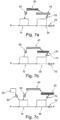
- Balloon catheter 110 is placed trough manifold side port 101", which is located at side trunk distal end 106 such that hemostasis valve 102" seals around ballooned catheter shaft 111.
- Occluding balloon 112 is attached to the distal end of ballooned catheter shaft 111 and placed in side trunk distal end 106 but does not reach main trunk proximal end 108. Inflating occluding balloon 112, by infusing fluid (preferably saline), will partially or fully occlude manifold side trunk 105 and will limit the amount of blood that circulates through manifold side trunk 105.
- occluding balloon 112 sets the portion of blood flowing through manifold side branch 105 and the portion of blood flowing through manifold main trunk distal end 109 and onward to outflow cannula 90.
- the blood flow through oxygenator 20 or the outflow cannula 90 depends on the degree to which the occluding balloon 112 is inflated.
- a fully inflated occluding balloon 112 will cause the blood flow from pump 10 to go entirely through outflow cannula 90 (with none flowing through the oxygenator 20).
- a fully deflated occluding balloon 112 will cause the blood flow from pump 10 to go entirely through oxygenator 20 (with none flowing through outflow cannula 90).
- Pump 10 may be set to deliver a flow rate in excess of what is desired to deliver to the patient, wherein all excess flow is re-circulated through the oxygenator 20 such that the blood is repeatedly subject to the exchange of O 2 and CO 2 within the oxygenator 20.
- the oxygenator 20 may be of substantially reduced size based on this "multiple pass” feature, wherein blood is passed multiple times over the oxygenator before being circulated to the patient.
- This "multiple pass” aspect of this invention simplifies the system and reduce its size and the blood volume needed to prime the circuit.
- Another advantage of this invention is the capability to place the circuit on the patient and therefore minimize the entire circuit complexity and size.
- FIG 5 illustrates yet another pump-oxygenator system according to the present invention.
- Manifold 100 includes a bubble trap 30 in main trunk 104 with blood pump 10 located at an inlet port 32 of bubble trap 30.
- Blood pump 10 empties all blood into bubble trap 30 before blood leaves to either manifold 100 side trunk 105 or to outflow cannula 90 and serves to remove any air bubbles from the pumped blood.
- Bubble trap 30 includes venting port 31 at the top of a conical top to vent any air entrapped in bubble trap 30.
- Inlet port 32 is preferably located close to the top end of bubble trap 30 while outlet port 33 is preferably located close to the bottom end.
- inlet port 32 of bubble trap 30 may be located to the side, rather than the center, of the main cavity 34 of the bubble trap 30 in order to enhance the formation of a vortex in the pumped blood. This will help increase the dwell time of the pumped blood in the bubble trap 30 and will capitalize on the centrifugal force to separate smaller air bubbles from the pumped blood.
- Bubble trap 30 may also include a screen (not shown) to trap any debris from the pumped blood.
- Pump 10 although shown in FIGS. 4 and 5 as being of axial design, may be centrifugal in design without affecting the function of this invention.
- FIG. 6 illustrates a pump-oxygenator system of the present invention similar to that of FIG. 5 , except for the addition of a heat exchanger 40.
- Heat exchanger 40 may preferably be a catheter system formed by a dual lumen catheter 41, wherein a fluid (heated or cooled) is injected through one lumen to heat or cool heating fibers 42.
- Heating fibers 42 are hollow fibers that are made of heat conducting material that are pliable and resist kinking to allow advancement into side trunk 105 of manifold 100 as shown in FIG. 6 .
- Any number of suitable materials may be employed for the heat exchanger 40, including but not limited to polymeric or metallic material such as Nitinol.
- heating fibers 42 are in communication with one lumen of dual lumen catheter 41 while the other end of heating fibers 42 is in communication with the other lumen of dual lumen catheter 41. Therefore, pumping fluid in the first lumen of dual lumen catheter 41 will direct the fluid to heating fibers 42 first such that heat will be delivered or removed from the circulating blood before the fluid exits through the second lumen.
- FIG 6a illustrates a pump-oxygenator system of the present invention, wherein oxygenator 20 is inserted through manifold side port 101 into main trunk 104 of manifold 100 and advanced into oxygen compartment 35 of bubble trap 30. Blood flowing from inflow cannula 80 enters through oxygen compartment 35 and gets deflected upwardly by deflector 36 before it reaches bubble trap compartment 37. Bubble trap compartment 37 allows any air bubbles to float to the top of bubble trap 30 and be removed through venting port 31. Deflector 36 and the design of bubble trap 30 in general may be fashioned to enhance the formation of a vortex flow at the top of bubble trap 30 to enhance the capability of isolating air bubbles in the top portion of bubble trap 30.
- Occluding balloon 112 may be synchronized with the heart rhythm.
- occluding balloon 112 may be fully deflated during systole (keeping the systemic pressure to a minimum to allow the heart to eject with minimal effort) and fully inflated during diastole (causing all oxygenated blood in bubble trap 30 to empty into the patients through outflow cannula 90).
- bubble trap 30 may have a volume which matches the average patient's stroke volume or less, such that for each heart cycle the system empties oxygenated blood contained in bubble trap 30 before occluding balloon fully deflates and starts re-circulating non-oxygenated blood drained from the venous system through inflow cannula 80.
- the present embodiment is designed to drain venous blood and infuse oxygenated blood during heart diastole and to re-circulate blood past the oxygenator during heart systole. This will advantageously result in the heart pumping against lower systemic pressure, which translates into a lower workload on the myocardium.
- FIG 6b illustrates a pump-oxygenator system of the present invention, which is substantially identical to that illustrated in FIG 6a .
- An extra pump 50 is positioned at the outflow cannula 90 to deliver a set volume to the patient.
- This extra pump 50 may be controlled independently from the main blood pump 10 that circulate the blood in the oxygenator portion of the device. Therefore, the blood volume delivered to the patient could be instantaneously changed according to the patient requirements.
- FIGS. 7a - 7c represent alternative arrangements for the system components shown, by way of example only, in FIGS. 1-6 .
- FIG. 7a is basically the same system depicted in more details in FIG. 6 with the addition of two flow meters, re-circulation flow meter 70 and outflow flow meter 70' that measure flow rate in the respective part of the circuit.
- FIG. 7b is the same as circuit 7a with oxygenator 20 and heat exchanger 40 reversed in location in the circuit. This arrangement may beneficial in some application versus other. For example, it might be preferable to cool blood after it has passed through oxygenator 20.
- FIG. 7c shows the addition of reservoir 60 to the system. Reservoir 60 may be used to store some blood volume that may be added to the circulation in case blood collection from patient becomes interrupted.
- reservoir 60 may be used to store excess in blood volume from the patient or may blood intended for transfusion into the patient, therefore the pump is used to introduce this extra blood.
- Reservoir 60 may be in series with inflow cannula 80 (not shown) instead of being in parallel (as shown in FIG. 7c ).
- pump 10 will siphon blood from the reservoir (assuming the reservoir is made from soft pliable walls) instead of siphoning directly from the patient.
- the advantage of this arrangement is the buffering of the pump suction from acting on the patient.
- occluding balloon 112 controls the portion of blood that returns to the pump inlet and the portion of blood that flows to the patient. Blood has the preference to re-circulate to the pump inlet since it is the least resistive path for the blood flow. As such, the more the occluding balloon 112 is inflated, the more flow will diverted to the patient. Stated another way, occluding balloon 112 determines the ratio of blood returning to the pump 10 from the outflow cannula 90 versus the new blood coming from inflow cannula 80. The rotational rate of the pump 10 determines the total volume of blood flowing through pump 10.
- a high flow rate is typically desired since the higher the flow rate of pump 10 relative to outflow cannula 90, the more oxygenation will take place.
- the higher the re-circulating blood portion the smaller the oxygenator 20 may be since the same blood will pass multiple times over oxygenator 20 and get a higher level of oxygenation. It may be desired at times to use a vacuum source to drive the flow of oxygen in the system rather than positive pressure. Vacuum driving will favor blood entry into the micropores of oxygenation fibers 25 rather than air leaving into the blood.
- a significant aspect of the pump-oxygenator system of the present invention is the capability of easily replacing components without stopping the system operation of pump 10, oxygenator 20, heat exchanger 40, and balloon catheter 110. This eliminates one of the main drawbacks of prior art, which required the entire system to be stopped in order to replace even one element. This, in turn, required subsequent re-priming of the system after the replacement procedure had taken place.
- This "switch out" capability of the present invention is a significant improvement over the prior art in that component replacement is frequently required due to fast degradation of oxygenator elements.
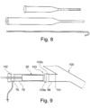
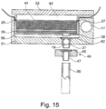
- FIG. 9 shows one manner of accomplishing the "switch out” feature of the present invention.
- Oxygenator 20 for example, may be placed inside soft tube 75, which may be made from silicone or similar soft medical tubing.
- the proximal end of soft tube 75 may be preferably equipped with venting port coupling 76 coupled to hemostasis valve 102.
- the distal end of soft tube 75 is fitted with quick-connect fitting 103a (male), wherein quick-connect fitting 103b (female) is attached to manifold side 101 of manifold 100.
- clamping section 99 (which is made of similar material to soft tube 75) is clamped using a standard tubing clamp.
- Quick-connect fitting 103a may then be coupled to quick-connect fitting 103b (to thereby form a unitary quick-connect coupling 103).
- the clamp may then be removed from clamping section 99, which serves to force blood into soft tube 75 and oxygenator 20.
- Air may be removed from soft tube 75 through venting coupling 76 and may be augmented by tapping, massaging, knocking soft tube 75 to release any entrapped air in oxygenator 20.
- oxygenator 20 may be advanced through quick-connect 103 and clamping section 99 into manifold 100 without interrupting system operation.
- oxygenator 20 may be pulled back into soft tube 75 by pulling the oxygenator sheath 23 until oxygenator 20 is past quick-connect 103. Clamping section 99 may then be clamped using a standard tube clamp. At this point, quick-connect 103 may be separated into its quick-connect male fitting 103a and quick-connect female fitting 103b such that the existing oxygenator 20, soft tube 75, venting coupling 76, and hemostasis valve 102 may be replaced by a new set. The same removal replacement method may be used for other component such as, pump 10, heat exchanger 40, or ballooned catheter 110.
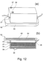
- FIG. 10 illustrates another pump-oxygenator system according to the present invention comprising an extracorporeal system 8 including a base 51, a lower oxygenator cartridge 52, an upper oxygenator cartridge 53, an integrated pump compartment 17, and a sterile barrier 54.
- base 51 comprises two cavities, namely, an upper oxygenator compartment 57 and a lower oxygenator compartment 56, which are located on one side of base 51 (referred to as the "top side” herein) and shaped to receive upper oxygenator cartridge 53 and lower oxygenator cartridge 52, respectively.
- Base 51 also includes an integrated pump (not shown), which is fully encapsulated inside the walls of base 51 and preferably a standard miniaturized rotary pump of the centrifugal type with an integrated electric motor encapsulated inside pump compartment 17 of base 51.
- the inflow port of the integrated pump (not shown) is in direct communication with the system inflow opening 18 located on the opposite side (referred to as the "bottom side” herein) of lower oxygenator compartment 56 and adjacent to the system outflow opening 19.
- Sterile barrier 54 is preferably an adhesive and/or foam base material that is disposed at the periphery of base 51 on the bottom side to interface with the patient skin and form a seal between the inside and outside area formed by sterile barrier 54.
- Sterile barrier 54 may preferably be saturated with a concentrated antibacterial and antiviral solution that prevents the crossing of any living organism from the outside to the inside of sterile barrier 54.
- Sterile barrier 54 may be made of flexible material and shaped to allow the use of suction (not shown) along its entire length to assure the adhesion between sterile barrier 54 and the patient skin.
- each oxygenator cartridge (lower oxygenator cartridge 52 and upper oxygenator cartridge 53) comprises a cartridge inflow 37 and a cartridge outflow 38 in communication with cartridge cavity 43.
- a matrix 44 of hollow fibers (of the type typically used in artificial oxygenators) is layered on top of a blood filtering material, filter mesh 39 (of a type typically used in filtering blood during bypass surgery).
- Matrix 44 is arranged to receive oxygen mixture, into the interior lumen of the hollow fibers, through oxygen inflow port 26 and return oxygen and carbon dioxide to oxygen outflow port 27 without introducing any gas bubbles into the blood flowing on the exterior surface of the hollow fibers of matrix 44. Blood will pass through filter mesh 39 before exiting the cartridge to capture any particles before entering the patient's blood stream.
- Filter mesh 39 may be designed to capture particles seized generally larger than 100 micrometers and preferably larger than 25 micrometers.
- Oxygenator cartridges 52, 53 may also include a heat exchange element 64, which is a thermal resistor that may be heated electrically. Heat exchange element 64 is mainly used to heat top plate 65 of lower oxygenator cartridge 52 in the case it is desired to heat any blood going through system 8. Upper oxygenator cartridge 53 may be similarly equipped with a heat exchange element (not shown) for the same purpose mentioned above. Alternatively, a manifold design (not shown) may be incorporated in top plate 65 of lower oxygenator cartridge 52 to allow the circulation of cooled or heated fluid in order to cool or heat blood circulating through system 8 if desired by the user. The cooling or heating fluid may be circulated by a miniature pump similar to standard pumps used in bypass surgery for the same purpose (not shown).
- inflow cannula 80 and outflow cannula 90 may be are attached to a plate 49.
- Plate 49 preferably comprises two barbed fittings (inflow barbed fitting 48 and outflow barbed fitting 47) designed to receive the proximal end of inflow cannula 80 and outflow cannula 90 respectively ( Fig 14 shows only one cannula connection, the other connection is identical but not shown).
- Inflow barbed fitting 48 and outflow barbed fitting 47 may have standard barbs (not shown) used in standard medical connector used in connecting PVC tubing to a tubing connector.
- plate 49 may include inflow hemostasis valve 46 and outflow hemostasis valve 45 that seal blood inside the cannula and air outside the cannula prior to attachment of plate 49 to base 51.
- Both inflow hemostasis valve 46 and outflow hemostasis valve 45 may have a central perforation or slits (not shown) so as to allow the insertion of a rigid tube (such as system inflow 22 and system outflow 21) into inflow hemostasis valve 46 and outflow hemostasis valve 45, respectively.
- system inflow 22 and system outflow 21 engage hemostasis valve 46 and outflow hemostasis valve 45, respectively, and allow blood to freely flow from and/or into the respective cannula 80, 90.
- lower oxygenator cartridge 52 is designed to fit lower oxygenator compartment 56 and engage system outflow opening 19 by pushing cartridge outflow 38 through lower compartment hemostasis valve 62, which functions similarly to outflow hemostasis valve 45.
- the removal of lower oxygenator cartridge 52 causes the full closure of lower compartment hemostasis valve 56 and containment of blood inside and air outside the manifold of system 8.
- This design allows the replacement of either oxygenator cartridge (lower oxygenator cartridge 52 and upper oxygenator cartridge 53) without introducing any air into the system or the need to stop the system operation. Only one oxygenator cartridge 52, 53 may be changed at a time in order to keep system 8 operational.
- the respective oxygenator compartment 56, 57 may be filled with sterile fluid (such as sterile saline) in order to remove any air in the proximity of the respective hemostasis valve 62, 63. This is done to eliminate the possibility of introducing air into the system during cartridge replacement.
- oxygenator cartridges 52, 53 are supplied sterile to the user and may be primed by sterile fluid to remove any air prior to connection to system 8.
- fluid may be circulated through the oxygenator cartridge 52, 53 while it is partially inserted into the appropriate oxygenator compartment 56, 57 that has already been filled with fluid. This step would flush any air from the system 8 to the outside atmosphere prior to connecting the oxygenator cartridge 52, 53.
- a small circulating pump (not shown) may be used for this step to completely prime the oxygenator cartridge 52, 53 before use.
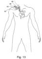
- FIG. 16 illustrates the system 8 mounted to a patient chest to allow free movement of the patient.
- a backpack (not shown) may be worn by the patient that may provide control, power, oxygen, and other functions (such as a small pump to circulate heating or cooling fluid) to system 8.
- an electronic controller that controls many of the invention feature (such as pump speed, oxygen gas volume delivery, blood heating) and many diagnostic sensors that indicates the proper performance of the system is required.
- the specifics of such controller are common those skilled in the art.
Landscapes
- Health & Medical Sciences (AREA)
- Heart & Thoracic Surgery (AREA)
- Engineering & Computer Science (AREA)
- Cardiology (AREA)
- Life Sciences & Earth Sciences (AREA)
- Biomedical Technology (AREA)
- Hematology (AREA)
- Anesthesiology (AREA)
- Animal Behavior & Ethology (AREA)
- General Health & Medical Sciences (AREA)
- Public Health (AREA)
- Veterinary Medicine (AREA)
- Mechanical Engineering (AREA)
- Vascular Medicine (AREA)
- Emergency Medicine (AREA)
- Pulmonology (AREA)
- Urology & Nephrology (AREA)
- External Artificial Organs (AREA)
Claims (16)
- Blutpumpen-Oxygenator-System zur Erhöhung der Perfusion und des Sauerstoffgehalts in einem Patienten, umfassend mindestens eine Blutpumpe (10), einen Oxygenator (20), eine Zuführungskanüle (80) und eine Abführungskanüle (90), die miteinander verbunden sind und einen geschlossenen Serienkreislauf bilden, der als kardiopulmonales Bypass-System für die extrakorporale Verarbeitung des Blutes des Patienten betrieben werden kann,wobei die Blutpumpe (10) eingerichtet ist, Blut durch den Kreislauf vom Patienten in die Zuführungskanüle (80), durch den Oxygenator (20) und aus der Abführungskanüle (90) zurück in den Patienten zu fördern,wobei das System des Weiteren einen Verteiler (100) umfasst, der zwischen der Zuführungskanüle (80) und der Abführungskanüle (90) angeschlossen ist, sodass das Blut durch den Verteiler (100) strömt,wobei der Verteiler (100) die Blutpumpe (10) und den Oxygenator (20) aufnimmt und eingerichtet ist, eine Rezirkulationsschleife zu bilden, durch die zumindest ein Teil des Blutes im Kreislauf rezirkuliert wird, sodass das Blut mehrfach über den Oxygenator (20) geführt wird,dadurch gekennzeichnet, dass das System des Weiteren eine zusätzliche Blutpumpe (50) umfasst, die an der Abführungskanüle (90) positioniert ist und eingerichtet ist, ein vorgegebenes Volumen an den Patienten abzugeben,wobei die zusätzliche Blutpumpe (50) eingerichtet ist, unabhängig von der Blutpumpe (10) gesteuert zu werden, welche das Blut im Verteiler (100) einschließlich des Oxygenators (20) zirkuliert, unddass die Blutpumpe (10) und der Oxygenator (20) als modulare Komponenten ausgeführt sind, um den Austausch von mindestens einer der Blutpumpe (10) und dem Oxygenator (20) zu ermöglichen.
- Blutpumpen-Oxygenator-System nach Anspruch 1, wobei die Blutpumpe (10) eingerichtet ist, auf eine Förderrate eingestellt zu werden, die über der gewünschten Förderrate an den Patienten liegt, wobei der gesamte überschüssige Fluss durch den Oxygenator (20) rezirkuliert wird, sodass das Blut wiederholt dem Austausch von O2 und CO2 im Oxygenator (20) unterzogen wird.
- Blutpumpen-Oxygenator-System nach Anspruch 1 oder 2, wobei der Verteiler (100) einen Hauptstrang (104) und einen Seitenstrang (105) umfasst, wobei der Hauptstrang (104) ein proximales Ende (108) aufweist, das mit der Zuführungskanüle (80) verbunden ist, und ein distales Ende (109), das mit der Abführungskanüle (90) verbunden ist, wobei der Seitenstrang (105) ein proximales Ende (107) und ein distales Ende (106) aufweist, das mit dem Hauptstrang (104) verbunden ist, sodass die Rezirkulationsschleife gebildet wird.
- Blutpumpen-Oxygenator-System nach einem der vorhergehenden Ansprüche, wobei der Verteiler (100) mindestens einen seitlichen Verteileranschluss (101) umfasst, der eingerichtet ist, den Austausch von mindestens einer der Blutpumpe (10) und dem Oxygenator (20) zu ermöglichen.
- Blutpumpen-Oxygenator-System nach Anspruch 3 oder 4, wobei die Blutpumpe (10) durch einen ersten seitlichen Verteileranschluss (101) am Hauptstrang (104) eingeführt und in den Hauptstrang (104) vorgeschoben wird, stromabwärts von einer proximalen Verbindungsstelle des Seitenstrangs (105) mit dem Hauptstrang (104), und wobei der Oxygenator (20) durch einen zweiten seitlichen Verteileranschluss (101') am Seitenstrang (105) eingeführt und durch einen Abschnitt des Seitenstrangs (105) vorgeschoben wird, wobei jeweils zugehörige Hämostaseventile (102, 102') eine dichte Abdichtung um eine Pumpenhülle (13) bzw. eine Oxygenatorhülle (23) bilden, die sich jeweils durch den entsprechenden seitlichen Verteileranschluss (101, 101') erstreckt, oder
wobei die Blutpumpe (10) durch einen ersten seitlichen Verteileranschluss am Hauptstrang (104) eingeführt und in den Hauptstrang (104) vorgeschoben wird, stromaufwärts von einer distalen Verbindungsstelle des Seitenstrangs (105) mit dem Hauptstrang (104), und wobei der Oxygenator (20) durch einen zweiten seitlichen Verteileranschluss (101) in den Hauptstrang (104) eingeführt wird, stromaufwärts von der Blutpumpe (10). - Blutpumpen-Oxygenator-System nach Anspruch 5, wobei ein Ballonkatheter (110) durch einen dritten seitlichen Verteileranschluss (101') eingeführt wird, der ein Hämostaseventil (102") aufweist, das eine dichte Abdichtung um einen Ballonkatheterschaft (111) bildet, wobei ein Okklusionsballon (112) am Ballonkatheterschaft (111) angebracht und im Seitenstrang (105) stromabwärts vom Oxygenator (20) positioniert ist, wobei der Ballonkatheter (110) eingerichtet ist, die Menge des durch den Hauptstrang (104) und den Seitenstrang (105) des Verteilers (100) fließenden Blutes durch Aufblasen und Ablassen des Okklusionsballons (112) zu steuern,
wobei der Okklusionsballon (112) vorzugsweise eingerichtet ist, mit dem Herzrhythmus synchronisiert zu werden, wobei vorzugsweise der Okklusionsballon (112) während der Systole vollständig entleert und während der Diastole vollständig aufgeblasen wird. - Blutpumpen-Oxygenator-System nach einem der vorhergehenden Ansprüche, wobei der Verteiler (100) mit mindestens einem Schnellanschluss (103) ausgestattet ist, der eingerichtet ist, eine Verbindung und Trennung der Zuführungskanüle (80) und der Abführungskanüle (90) jeweils mit dem Verteiler (100) zu ermöglichen.
- Blutpumpen-Oxygenator-System nach einem der vorhergehenden Ansprüche, das des Weiteren ein Druckrückführungssystem umfasst, um die Pumpensaugkraft der Blutpumpe (10) zu steuern.
- Blutpumpen-Oxygenator-System nach einem der vorhergehenden Ansprüche, wobei das System eingerichtet ist, Gas im Oxygenator (20) mit Unterdruck zu zirkulieren.
- Blutpumpen-Oxygenator-System nach einem der vorhergehenden Ansprüche, das des Weiteren einen Gasheizer und Wärmedämmung umfasst.
- Blutpumpen-Oxygenator-System nach einem der vorhergehenden Ansprüche, wobei die Blutpumpe (10) eine Rotationspumpe oder eine Verdrängerpumpe ist, vorzugsweise eine Rotationspumpe des Zentrifugaltyps oder des Axialtyps, wobei die Blutpumpe (10) eingerichtet ist, direkt von einem Elektromotor angetrieben zu werden oder von einem flexiblen Antriebsstrang (14), der die Blutpumpe (10) entweder magnetisch oder direkt mit dem Elektromotor verbindet,
wobei weiter vorzugsweise die Blutpumpe (10) vom Axialfluss-Typ ist, mit einem Rotor (11), der sich innerhalb eines Pumpengehäuses (12) befindet, wobei der Antriebsstrang (14) innerhalb einer Hülle (13) mit dem Rotor (11) gekoppelt ist, sodass die Drehung des Antriebsstrangs (14) durch einen Elektromotor die Drehung des Rotors (11) verursacht und das Blut vom distalen Ende zum proximalen Ende des Gehäuses (12) gepumpt wird, um das Blut von der Zuführungskanüle (80) zur Abführungskanüle (90) zu transportieren. - Blutpumpen-Oxygenator-System nach einem der vorhergehenden Ansprüche, wobei die Blutpumpe (10) eingerichtet ist, in den Verteiler (100) eingeführt zu werden, indem sie durch einen ersten seitlichen Verteileranschluss (101) hindurchgeführt wird, wobei ein Hämostaseventil (102) um eine Hülle (13) schließt, die mit der Blutpumpe (10) verbunden ist, wobei das Hämostaseventil (102) Hämostase gewährleistet, nachdem die Blutpumpe (10) hindurchgeführt wurde.
- Blutpumpen-Oxygenator-System nach einem der vorhergehenden Ansprüche, wobei der Oxygenator (20) eingerichtet ist, in den Verteiler (100) durch einen zweiten seitlichen Verteileranschluss (101') eingeführt zu werden, wobei ein Hämostaseventil (102') eine Abdichtung um eine Oxygenatorhülle (23) bildet,
wobei die Oxygenatorhülle (23) vorzugsweise mindestens zwei Lumen aufweist, darunter ein Zuflusslumen (28) für die Sauerstoffzufuhr zum Oxygenator (20) und ein Abflusslumen (29) für die Entfernung von Kohlendioxid aus dem Oxygenator (20), wobei der Oxygenator (20) eine Vielzahl von hohlen Oxygenationsfasern (25) umfasst, die es ermöglichen, dass Blut zwischen den Oxygenatorfasern (25) hindurchströmt, um Sauerstoff aufzunehmen und Kohlendioxid abzugeben, während Sauerstoff durch ein inneres Lumen der Oxygenatorfasern (25) von dem Zuflusslumen (28) an einem Ende der Oxygenatorfasern (25) hindurchströmt und am anderen Ende der Oxygenatorfasern (25) in das Abflusslumen (29) zurückkehrt. - Blutpumpen-Oxygenator-System nach einem der vorhergehenden Ansprüche, wobei der Oxygenator (20) in der Größe auf den Innendurchmesser des Verteilers (100) abgestimmt ist, um eine enge Passung zu ermöglichen und den Blutfluss um den Oxygenator (20) zu begrenzen, sodass das Blut gezwungen wird, durch die Oxygenatorfasern (25) zu fließen.
- Blutpumpen-Oxygenator-System nach einem der vorhergehenden Ansprüche, wobei der Verteiler (100) eine Blasenfalle (30) umfasst, vorzugsweise im Hauptstrang (104), mit der Blutpumpe (10), die an einem Einlassanschluss (32) der Blasenfalle (30) positioniert ist, wobei die Blutpumpe (10) eingerichtet ist, sämtliches Blut in die Blasenfalle (30) zu leeren, bevor es die Blasenfalle (30) am Auslassanschluss (33) verlässt, wobei die Blasenfalle (30) einen Belüftungsanschluss (31) an der Spitze eines kegelförmigen oberen Teils aufweist, um Luft, die in der Blasenfalle (30) eingeschlossen ist, zu entlüften, wobei der Einlassanschluss (32) vorzugsweise nahe dem oberen Ende der Blasenfalle (30) und der Auslassanschluss (33) vorzugsweise nahe dem unteren Ende positioniert ist.
- Blutpumpen-Oxygenator-System nach einem der vorhergehenden Ansprüche, das des Weiteren einen Wärmeübertrager (40) umfasst, der eingerichtet ist, die Temperatur des zirkulierenden Blutes zu regulieren, wobei der Wärmeübertrager (40) vorzugsweise ein Kathetersystem umfasst, das einen Doppellumenkatheter (41) umfasst, der eingerichtet ist, ein beheiztes oder gekühltes Fluid durch hohle Heizfasern (42) zu leiten, die aus wärmeleitendem Material bestehen, wobei ein Ende der Heizfasern (42) mit einem Lumen des Doppellumenkatheters (41) in Verbindung steht, während das andere Ende der Heizfasern (42) mit dem anderen Lumen des Doppellumenkatheters (41) in Verbindung steht.
Applications Claiming Priority (2)
| Application Number | Priority Date | Filing Date | Title |
|---|---|---|---|
| US202062981079P | 2020-02-25 | 2020-02-25 | |
| PCT/EP2021/054671 WO2021170712A1 (en) | 2020-02-25 | 2021-02-25 | Combined blood pump and oxygenator system and related methods |
Publications (3)
| Publication Number | Publication Date |
|---|---|
| EP4110423A1 EP4110423A1 (de) | 2023-01-04 |
| EP4110423B1 true EP4110423B1 (de) | 2025-04-23 |
| EP4110423C0 EP4110423C0 (de) | 2025-04-23 |
Family
ID=74844883
Family Applications (1)
| Application Number | Title | Priority Date | Filing Date |
|---|---|---|---|
| EP21708954.9A Active EP4110423B1 (de) | 2020-02-25 | 2021-02-25 | Kombination aus blutpumpe und oxygenatorsystem und zugehörige verfahren |
Country Status (5)
| Country | Link |
|---|---|
| US (2) | US12458789B2 (de) |
| EP (1) | EP4110423B1 (de) |
| JP (1) | JP7545621B2 (de) |
| CN (1) | CN115515660A (de) |
| WO (1) | WO2021170712A1 (de) |
Families Citing this family (4)
| Publication number | Priority date | Publication date | Assignee | Title |
|---|---|---|---|---|
| CA3251955A1 (en) * | 2022-05-09 | 2023-11-16 | The Texas A&M University System | Bidirectional blood pumps and unidirectional filter traps and systems comprising them |
| EP4483916A1 (de) | 2023-06-27 | 2025-01-01 | BIOxy Med LLC-FZ | Kombination aus blutpumpe und oxygenatorsystem |
| EP4483915A1 (de) | 2023-06-27 | 2025-01-01 | BIOxy Med LLC-FZ | Kombination aus blutpumpe und oxygenatorsystem |
| CN117815475B (zh) * | 2024-01-05 | 2024-11-19 | 江苏赛腾医疗科技有限公司 | 一种高效过滤的膜式氧合器 |
Family Cites Families (20)
| Publication number | Priority date | Publication date | Assignee | Title |
|---|---|---|---|---|
| GB1061597A (en) | 1962-12-28 | 1967-03-15 | Bruce Robinson Bodell | Device for effecting blood interchange functions |
| US3890969A (en) | 1974-01-21 | 1975-06-24 | Baxter Laboratories Inc | Cardiopulmonary bypass system |
| US4159720A (en) | 1977-11-28 | 1979-07-03 | Burton Andrew F | Infusion of liquids into tissue |
| US4346006A (en) | 1980-03-24 | 1982-08-24 | Baxter Travenol Laboratories, Inc. | Diffusion membrane units with adhered semipermeable capillaries |
| US4466804A (en) | 1981-09-25 | 1984-08-21 | Tsunekazu Hino | Extracorporeal circulation of blood |
| US4540399A (en) | 1983-02-01 | 1985-09-10 | Ken Litzie | Emergency bypass system |
| US4631053A (en) | 1984-03-19 | 1986-12-23 | Taheri Syde A | Oxygenator |
| US4583969A (en) | 1984-06-26 | 1986-04-22 | Mortensen J D | Apparatus and method for in vivo extrapulmonary blood gas exchange |
| US4610656A (en) | 1984-08-21 | 1986-09-09 | Mehealus Partnership | Fully portable semi-automatic mechanical heart-lung substitution system and method |
| JPS6192666A (ja) | 1984-10-15 | 1986-05-10 | 東レ株式会社 | 人工血管 |
| US4944722A (en) | 1989-02-23 | 1990-07-31 | Nimbus Medical, Inc. | Percutaneous axial flow blood pump |
| US5186431A (en) * | 1989-09-22 | 1993-02-16 | Yehuda Tamari | Pressure sensitive valves for extracorporeal circuits |
| US5411706A (en) * | 1994-02-09 | 1995-05-02 | Hubbard; Lloyd C. | Pump/oxygenator with blood recirculation |
| JP3360995B2 (ja) * | 1995-10-04 | 2003-01-07 | テルモ株式会社 | 人工心肺装置および貯血槽付人工肺 |
| US6117390A (en) * | 1998-03-27 | 2000-09-12 | Medtronic, Inc. | Compact blood oxygenator utilizing longitudinally interspersed transversely extending heat exchanger conduits and oxygenator fibers |
| US6773670B2 (en) * | 2001-02-09 | 2004-08-10 | Cardiovention, Inc. C/O The Brenner Group, Inc. | Blood filter having a sensor for active gas removal and methods of use |
| JP2013233333A (ja) | 2012-05-10 | 2013-11-21 | Kawasumi Lab Inc | 血液浄化装置及び血液浄化システム |
| IT201700038389A1 (it) | 2017-04-07 | 2018-10-07 | In10Sivecare S R L | Apparecchiatura per il trattamento extracorporeo del sangue |
| IT201800006973A1 (it) | 2018-07-05 | 2020-01-05 | Apparecchiatura per il trattamento del sangue e relativo metodo di inizializzazione. | |
| US20240033408A1 (en) * | 2022-07-28 | 2024-02-01 | Cardiacassist, Inc. | Extracorporeal life support system with blood recirculation pathway |
-
2021
- 2021-02-25 CN CN202180030539.XA patent/CN115515660A/zh active Pending
- 2021-02-25 EP EP21708954.9A patent/EP4110423B1/de active Active
- 2021-02-25 JP JP2022576235A patent/JP7545621B2/ja active Active
- 2021-02-25 WO PCT/EP2021/054671 patent/WO2021170712A1/en not_active Ceased
-
2022
- 2022-08-25 US US17/895,341 patent/US12458789B2/en active Active
-
2025
- 2025-10-13 US US19/357,033 patent/US20260034342A1/en active Pending
Also Published As
| Publication number | Publication date |
|---|---|
| US20230022901A1 (en) | 2023-01-26 |
| JP7545621B2 (ja) | 2024-09-05 |
| US20260034342A1 (en) | 2026-02-05 |
| US12458789B2 (en) | 2025-11-04 |
| CN115515660A (zh) | 2022-12-23 |
| EP4110423A1 (de) | 2023-01-04 |
| WO2021170712A1 (en) | 2021-09-02 |
| EP4110423C0 (de) | 2025-04-23 |
| JP2023528532A (ja) | 2023-07-04 |
Similar Documents
| Publication | Publication Date | Title |
|---|---|---|
| US12458789B2 (en) | Combined blood pump and oxygenator system and related methods | |
| CA2367469C (en) | Heart assist system | |
| US7122151B2 (en) | Membrane apparatus with enhanced mass transfer, heat transfer and pumping capabilities via active mixing | |
| US12171927B2 (en) | Wearable modular extracorporeal life support device for mobile treatment of single and multiorgan failure | |
| WO1999049913A1 (en) | Compact blood oxygenator and perfusion circuit | |
| US20220273853A1 (en) | Arrangement for Transporting a Liquid Through a Cannula System, Corresponding Kit and Method | |
| MXPA04000801A (es) | Anastomosis auricular-arterial de bajo flujo para revascularizacion del miocardio auxiliada por bomba sin derivacion cardiopulmonar. | |
| US20260097160A1 (en) | Combined blood pump and oxygenator system | |
| GB2629747A (en) | Extracorporeal life support system with blood recirculation pathway | |
| JP7777598B2 (ja) | 二重ルーメンカニューラ | |
| EP4483916A1 (de) | Kombination aus blutpumpe und oxygenatorsystem | |
| RU2812169C2 (ru) | Носимое модульное устройство экстракорпорального жизнеобеспечения для мобильного лечения единичной или полиорганной недостаточности | |
| CN119424897A (zh) | 一种用于循环辅助的导管装置及循环辅助系统 | |
| HK40116801A (en) | Wearable modular extracorporeal life support device for mobile treatment of single and multiorgan failure | |
| HK40052518B (en) | Wearable modular extracorporeal life support device for mobile treatment of single and multiorgan failure | |
| HK40052518A (en) | Wearable modular extracorporeal life support device for mobile treatment of single and multiorgan failure | |
| WO2005032621A1 (en) | Hameoperfusion apparatus for use during cardiac and/or vascular operative procedures |
Legal Events
| Date | Code | Title | Description |
|---|---|---|---|
| STAA | Information on the status of an ep patent application or granted ep patent |
Free format text: STATUS: UNKNOWN |
|
| STAA | Information on the status of an ep patent application or granted ep patent |
Free format text: STATUS: THE INTERNATIONAL PUBLICATION HAS BEEN MADE |
|
| PUAI | Public reference made under article 153(3) epc to a published international application that has entered the european phase |
Free format text: ORIGINAL CODE: 0009012 |
|
| STAA | Information on the status of an ep patent application or granted ep patent |
Free format text: STATUS: REQUEST FOR EXAMINATION WAS MADE |
|
| 17P | Request for examination filed |
Effective date: 20220922 |
|
| AK | Designated contracting states |
Kind code of ref document: A1 Designated state(s): AL AT BE BG CH CY CZ DE DK EE ES FI FR GB GR HR HU IE IS IT LI LT LU LV MC MK MT NL NO PL PT RO RS SE SI SK SM TR |
|
| DAV | Request for validation of the european patent (deleted) | ||
| DAX | Request for extension of the european patent (deleted) | ||
| RAP1 | Party data changed (applicant data changed or rights of an application transferred) |
Owner name: BIOXY MED LLC-FZ |
|
| GRAP | Despatch of communication of intention to grant a patent |
Free format text: ORIGINAL CODE: EPIDOSNIGR1 |
|
| STAA | Information on the status of an ep patent application or granted ep patent |
Free format text: STATUS: GRANT OF PATENT IS INTENDED |
|
| INTG | Intention to grant announced |
Effective date: 20241122 |
|
| GRAS | Grant fee paid |
Free format text: ORIGINAL CODE: EPIDOSNIGR3 |
|
| GRAA | (expected) grant |
Free format text: ORIGINAL CODE: 0009210 |
|
| STAA | Information on the status of an ep patent application or granted ep patent |
Free format text: STATUS: THE PATENT HAS BEEN GRANTED |
|
| AK | Designated contracting states |
Kind code of ref document: B1 Designated state(s): AL AT BE BG CH CY CZ DE DK EE ES FI FR GB GR HR HU IE IS IT LI LT LU LV MC MK MT NL NO PL PT RO RS SE SI SK SM TR |
|
| REG | Reference to a national code |
Ref country code: GB Ref legal event code: FG4D |
|
| REG | Reference to a national code |
Ref country code: CH Ref legal event code: EP |
|
| REG | Reference to a national code |
Ref country code: DE Ref legal event code: R096 Ref document number: 602021029572 Country of ref document: DE |
|
| REG | Reference to a national code |
Ref country code: IE Ref legal event code: FG4D |
|
| U01 | Request for unitary effect filed |
Effective date: 20250522 |
|
| U07 | Unitary effect registered |
Designated state(s): AT BE BG DE DK EE FI FR IT LT LU LV MT NL PT RO SE SI Effective date: 20250602 |
|
| PG25 | Lapsed in a contracting state [announced via postgrant information from national office to epo] |
Ref country code: ES Free format text: LAPSE BECAUSE OF FAILURE TO SUBMIT A TRANSLATION OF THE DESCRIPTION OR TO PAY THE FEE WITHIN THE PRESCRIBED TIME-LIMIT Effective date: 20250423 |
|
| PG25 | Lapsed in a contracting state [announced via postgrant information from national office to epo] |
Ref country code: GR Free format text: LAPSE BECAUSE OF FAILURE TO SUBMIT A TRANSLATION OF THE DESCRIPTION OR TO PAY THE FEE WITHIN THE PRESCRIBED TIME-LIMIT Effective date: 20250724 Ref country code: NO Free format text: LAPSE BECAUSE OF FAILURE TO SUBMIT A TRANSLATION OF THE DESCRIPTION OR TO PAY THE FEE WITHIN THE PRESCRIBED TIME-LIMIT Effective date: 20250723 |
|
| PG25 | Lapsed in a contracting state [announced via postgrant information from national office to epo] |
Ref country code: PL Free format text: LAPSE BECAUSE OF FAILURE TO SUBMIT A TRANSLATION OF THE DESCRIPTION OR TO PAY THE FEE WITHIN THE PRESCRIBED TIME-LIMIT Effective date: 20250423 |
|
| PG25 | Lapsed in a contracting state [announced via postgrant information from national office to epo] |
Ref country code: HR Free format text: LAPSE BECAUSE OF FAILURE TO SUBMIT A TRANSLATION OF THE DESCRIPTION OR TO PAY THE FEE WITHIN THE PRESCRIBED TIME-LIMIT Effective date: 20250423 |
|
| PG25 | Lapsed in a contracting state [announced via postgrant information from national office to epo] |
Ref country code: RS Free format text: LAPSE BECAUSE OF FAILURE TO SUBMIT A TRANSLATION OF THE DESCRIPTION OR TO PAY THE FEE WITHIN THE PRESCRIBED TIME-LIMIT Effective date: 20250723 |
|
| PG25 | Lapsed in a contracting state [announced via postgrant information from national office to epo] |
Ref country code: IS Free format text: LAPSE BECAUSE OF FAILURE TO SUBMIT A TRANSLATION OF THE DESCRIPTION OR TO PAY THE FEE WITHIN THE PRESCRIBED TIME-LIMIT Effective date: 20250823 |
|
| PG25 | Lapsed in a contracting state [announced via postgrant information from national office to epo] |
Ref country code: SM Free format text: LAPSE BECAUSE OF FAILURE TO SUBMIT A TRANSLATION OF THE DESCRIPTION OR TO PAY THE FEE WITHIN THE PRESCRIBED TIME-LIMIT Effective date: 20250423 |
|
| PG25 | Lapsed in a contracting state [announced via postgrant information from national office to epo] |
Ref country code: CZ Free format text: LAPSE BECAUSE OF FAILURE TO SUBMIT A TRANSLATION OF THE DESCRIPTION OR TO PAY THE FEE WITHIN THE PRESCRIBED TIME-LIMIT Effective date: 20250423 |
|
| PG25 | Lapsed in a contracting state [announced via postgrant information from national office to epo] |
Ref country code: SK Free format text: LAPSE BECAUSE OF FAILURE TO SUBMIT A TRANSLATION OF THE DESCRIPTION OR TO PAY THE FEE WITHIN THE PRESCRIBED TIME-LIMIT Effective date: 20250423 |
|
| PLBE | No opposition filed within time limit |
Free format text: ORIGINAL CODE: 0009261 |
|
| STAA | Information on the status of an ep patent application or granted ep patent |
Free format text: STATUS: NO OPPOSITION FILED WITHIN TIME LIMIT |
|
| REG | Reference to a national code |
Ref country code: CH Ref legal event code: L10 Free format text: ST27 STATUS EVENT CODE: U-0-0-L10-L00 (AS PROVIDED BY THE NATIONAL OFFICE) Effective date: 20260304 |
|
| 26N | No opposition filed |
Effective date: 20260126 |
|
| U20 | Renewal fee for the european patent with unitary effect paid |
Year of fee payment: 6 Effective date: 20260225 |