EP4110457B1 - Fil médical implantable avec blindage - Google Patents
Fil médical implantable avec blindage Download PDFInfo
- Publication number
- EP4110457B1 EP4110457B1 EP21714467.4A EP21714467A EP4110457B1 EP 4110457 B1 EP4110457 B1 EP 4110457B1 EP 21714467 A EP21714467 A EP 21714467A EP 4110457 B1 EP4110457 B1 EP 4110457B1
- Authority
- EP
- European Patent Office
- Prior art keywords
- electrode
- shield
- pace
- implantable medical
- defibrillation
- Prior art date
- Legal status (The legal status is an assumption and is not a legal conclusion. Google has not performed a legal analysis and makes no representation as to the accuracy of the status listed.)
- Active
Links
Images






Classifications
-
- A—HUMAN NECESSITIES
- A61—MEDICAL OR VETERINARY SCIENCE; HYGIENE
- A61N—ELECTROTHERAPY; MAGNETOTHERAPY; RADIATION THERAPY; ULTRASOUND THERAPY
- A61N1/00—Electrotherapy; Circuits therefor
- A61N1/18—Applying electric currents by contact electrodes
- A61N1/32—Applying electric currents by contact electrodes alternating or intermittent currents
- A61N1/38—Applying electric currents by contact electrodes alternating or intermittent currents for producing shock effects
- A61N1/39—Heart defibrillators
- A61N1/3956—Implantable devices for applying electric shocks to the heart, e.g. for cardioversion
- A61N1/3962—Implantable devices for applying electric shocks to the heart, e.g. for cardioversion in combination with another heart therapy
- A61N1/39622—Pacing therapy
-
- A—HUMAN NECESSITIES
- A61—MEDICAL OR VETERINARY SCIENCE; HYGIENE
- A61N—ELECTROTHERAPY; MAGNETOTHERAPY; RADIATION THERAPY; ULTRASOUND THERAPY
- A61N1/00—Electrotherapy; Circuits therefor
- A61N1/18—Applying electric currents by contact electrodes
- A61N1/32—Applying electric currents by contact electrodes alternating or intermittent currents
- A61N1/36—Applying electric currents by contact electrodes alternating or intermittent currents for stimulation
- A61N1/3605—Implantable neurostimulators for stimulating central or peripheral nerve system
- A61N1/36128—Control systems
- A61N1/36146—Control systems specified by the stimulation parameters
- A61N1/36182—Direction of the electrical field, e.g. with sleeve around stimulating electrode
-
- A—HUMAN NECESSITIES
- A61—MEDICAL OR VETERINARY SCIENCE; HYGIENE
- A61N—ELECTROTHERAPY; MAGNETOTHERAPY; RADIATION THERAPY; ULTRASOUND THERAPY
- A61N1/00—Electrotherapy; Circuits therefor
- A61N1/18—Applying electric currents by contact electrodes
- A61N1/32—Applying electric currents by contact electrodes alternating or intermittent currents
- A61N1/36—Applying electric currents by contact electrodes alternating or intermittent currents for stimulation
- A61N1/362—Heart stimulators
- A61N1/3621—Heart stimulators for treating or preventing abnormally high heart rate
- A61N1/3622—Heart stimulators for treating or preventing abnormally high heart rate comprising two or more electrodes co-operating with different heart regions
-
- A—HUMAN NECESSITIES
- A61—MEDICAL OR VETERINARY SCIENCE; HYGIENE
- A61N—ELECTROTHERAPY; MAGNETOTHERAPY; RADIATION THERAPY; ULTRASOUND THERAPY
- A61N1/00—Electrotherapy; Circuits therefor
- A61N1/18—Applying electric currents by contact electrodes
- A61N1/32—Applying electric currents by contact electrodes alternating or intermittent currents
- A61N1/36—Applying electric currents by contact electrodes alternating or intermittent currents for stimulation
- A61N1/372—Arrangements in connection with the implantation of stimulators
- A61N1/375—Constructional arrangements, e.g. casings
- A61N1/37512—Pacemakers
-
- A—HUMAN NECESSITIES
- A61—MEDICAL OR VETERINARY SCIENCE; HYGIENE
- A61N—ELECTROTHERAPY; MAGNETOTHERAPY; RADIATION THERAPY; ULTRASOUND THERAPY
- A61N1/00—Electrotherapy; Circuits therefor
- A61N1/02—Details
- A61N1/04—Electrodes
- A61N1/05—Electrodes for implantation or insertion into the body, e.g. heart electrode
- A61N1/0504—Subcutaneous electrodes
-
- A—HUMAN NECESSITIES
- A61—MEDICAL OR VETERINARY SCIENCE; HYGIENE
- A61N—ELECTROTHERAPY; MAGNETOTHERAPY; RADIATION THERAPY; ULTRASOUND THERAPY
- A61N1/00—Electrotherapy; Circuits therefor
- A61N1/18—Applying electric currents by contact electrodes
- A61N1/32—Applying electric currents by contact electrodes alternating or intermittent currents
- A61N1/36—Applying electric currents by contact electrodes alternating or intermittent currents for stimulation
- A61N1/362—Heart stimulators
-
- A—HUMAN NECESSITIES
- A61—MEDICAL OR VETERINARY SCIENCE; HYGIENE
- A61N—ELECTROTHERAPY; MAGNETOTHERAPY; RADIATION THERAPY; ULTRASOUND THERAPY
- A61N1/00—Electrotherapy; Circuits therefor
- A61N1/18—Applying electric currents by contact electrodes
- A61N1/32—Applying electric currents by contact electrodes alternating or intermittent currents
- A61N1/38—Applying electric currents by contact electrodes alternating or intermittent currents for producing shock effects
- A61N1/39—Heart defibrillators
- A61N1/3918—Heart defibrillators characterised by shock pathway, e.g. by electrode configuration
Definitions
- the present application relates to implantable medical leads and, more particularly, implantable medical leads with one or more structures to reduce the likelihood of stimulation of unintended tissue.
- VF ventricular fibrillation
- SCD sudden cardiac death
- Implantable systems such as an implantable cardioverter defibrillator (ICD) system has been shown to be beneficial at preventing SCD.
- Implantable systems such as pacemakers with or without cardioversion or defibrillation capabilities, may also treat other cardiac dysfunction, such as bradycardia and heart failure.
- Such implantable systems may include electrical devices configured to deliver therapy via electrodes. Therapy may include shocks and/or anti-tachycardia pacing (ATP).
- ATP anti-tachycardia pacing
- the implantable systems may also be configured to deliver cardiac pacing to, for example, treat bradyarrhythmia or for cardiac resynchronization therapy (CRT).
- CTR cardiac resynchronization therapy
- the implantable system may include one or more implantable medical leads.
- a distal portion of an implantable medical lead may include one or more electrodes, and may be positioned at a target location within the patient for delivery of electrical therapy and/or electrical sensing via the electrodes.
- a proximal end of the lead may be coupled to the implantable system.
- the implantable system may also include one or more housing electrodes, which are sometimes referred to as can electrodes, for delivery of therapy and/or sensing.
- subcutaneous implantable systems have been devised, in which the implantable system and leads are located subcutaneously outside of the thorax. It has also been proposed that the distal portion of a lead of an implantable system may be implanted within the thorax, but not in contact with the heart, e.g., substernally.
- an extracardiac vessel that is within the thorax, such as the internal thoracic vein (ITV), the intercostal veins, the superior epigastric vein, or the azygos, hemiazygos, and accessory hemiazygos veins.
- ITV internal thoracic vein
- the intercostal veins such as the intercostal veins, the superior epigastric vein, or the azygos, hemiazygos, and accessory hemiazygos veins.
- Implantable medical leads are also used to deliver therapies to tissues other than the heart. Implantable medical leads may be used to position one or more electrodes within or near target nerves, muscles, or organs to deliver electrical stimulation to such tissues. As examples, implantable medical leads may be positioned in the epidural space to deliver spinal cord stimulation, or proximate to other nerves, such as pelvic nerves or renal nerves, to deliver neurostimulation to the nerves.
- US 2007/239244 A1 relates generally to cardiac leads carrying electrodes for electrically stimulating body tissue and/or for sensing the electrical activity of such tissue.
- Electrodes on or within the heart delivery of pacing pulses using electrodes of extravascular leads may require higher energy levels to capture the heart.
- conventional pace electrodes placed extravascularly may direct a significant portion of the electrical field produced by a pacing pulse away from the heart.
- the electrical field directed away from the heart may stimulate extracardiac tissue, such as the phrenic nerve, nerve endings in the intercostal regions, or other sensory or motor nerves.
- Electrodes are implanted within extracardiac vessels within the thorax, such as the ITV, the intercostal veins, the superior epigastric vein, or the azygos, hemiazygos, and accessory hemiazygos veins, or when electrodes are implanted in other extracardiac locations.
- the invention provides an implantable medical lead according to claim 1 and a method of manufacturing of said implantable medical lead, according to claim 15.
- implantable medical leads and implantable systems such as ICD systems, utilizing the leads.
- implantable medical leads that include a shield configured to impede the electric field from a pacing pulse, e.g., block or reduce the electric field, in a direction from the pace electrode, away from the heart, e.g., an anterior direction.
- the shield may reduce the likelihood that pacing pulses delivered via the pace electrode stimulate extracardiac tissue, such as sensory or motor nerves, which may reduce pain or other sensations associated with capture of such tissue.
- the shield may direct the electrical field toward the heart, allowing lower energy level pacing pulses to capture the heart than may be required without the shield.
- Lower energy pacing pulses may also reduce the likelihood that pacing pulses delivered via the pace electrode stimulate extracardiac tissue, and may result is less consumption of the power source of the ICD and, consequently, longer service life for the ICD.
- implantable medical leads having one or more shields may be used in contexts other than that of ICD systems, both cardiac and non-cardiac.
- implantable medical leads that have a shield over a portion of a surface of an electrode may be used with an extracardiac pacemaker system without defibrillation capabilities.
- implantable medical leads that have a shield over a portion of a surface of an electrode may impede an electrical field resulting from delivery of neurostimulation from the electrode in a direction away from a target nerve. In this manner, the shield may direct the neurostimulation to intended tissue, and reduce the likelihood that the neurostimulation stimulates unintended tissues.
- an implantable medical lead comprises a first defibrillation electrode and a second defibrillation electrode, the first and second defibrillation electrodes configured to deliver anti tachyarrhythmia shocks, and a pace electrode disposed between the first defibrillation electrode and the second defibrillation electrode, the pace electrode configured to deliver a pacing pulse that generates an electric field proximate to the pace electrode.
- the implantable medical lead further comprises a shield disposed between the first defibrillation electrode and the second defibrillation electrode, over a portion of an outer surface of the pace electrode, and extending laterally away from the pace electrode, wherein the shield is configured to impede the electric field in a direction from the pace electrode away from a heart.
- an implantable cardioverter-defibrillator (ICD) system comprises the implantable medical lead as described above and an ICD configured to deliver the pacing pulse via the pace electrode.
- a method of implanting an implantable medical lead which does not form part of the invention, as described above comprises advancing the implantable medical lead to a location within the patient, and rotationally orienting the distal portion of implantable medical lead such that the shield is positioned opposite a heart relative to the pace electrode.
- a method of manufacturing an implantable medical lead as described above comprises attaching the shield to the surface of the pace electrode, and subsequently assembling the shield and the pace electrode on the implantable medical lead.
- relational terms such as “first” and “second,” “over” and “under,” “front” and “rear,” and the like, may be used solely to distinguish one entity or element from another entity or element without necessarily requiring or implying any physical or logical relationship or order between such entities or elements.
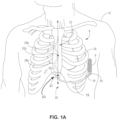
- FIGS. 1A-C conceptual diagrams illustrating various views of an example extracardiovascular implantable cardioverter-defibrillator (ICD) system 8.
- ICD system 8 includes an ICD 9 connected to an implantable medical lead 10.
- FIG. 1A is a front view of a patient implanted with extracardiovascular ICD system 8.
- FIG. 1B is a side view of the patient implanted with extracardiovascular ICD system 8.
- FIG. 1C is a transverse view of the patient implanted with extracardiovascular ICD system 8.
- ICD 9 may include a housing that forms a hermetic seal that protects components of the ICD 9.
- the housing of ICD 9 may be formed of a conductive material, such as titanium or titanium alloy, which may function as a housing electrode (sometimes referred to as a can electrode).
- ICD 9 may be formed to have or may include a plurality of electrodes on the housing.
- ICD 9 may also include a connector assembly (also referred to as a connector block or header) that includes electrical feedthroughs through which electrical connections are made between conductors of lead 10 and electronic components included within the housing of ICD 9.
- the housing may house one or more processors, memories, transmitters, receivers, sensors, sensing circuitry, therapy circuitry, power sources and other appropriate components.
- the housing is configured to be implanted in a patient, such patient 12.
- ICD 9 is implanted extra-thoracically on the left side of the patient, e.g., under the skin and outside the ribcage (subcutaneously or submuscularly). ICD 9 may, in some instances, be implanted between the left posterior axillary line and the left anterior axillary line of the patient. ICD 9 may, however, be implanted at other extra-thoracic locations on the patient as described later.
- Lead 10 may include an elongated lead body 13 having a distal portion 16 sized to be implanted in an extracardiovascular location proximate the heart, e.g., intra-thoracically, as illustrated in FIGS. 1A-C , or extra-thoracically.
- lead 10 may extend extra-thoracically under the skin and outside the ribcage (e.g., subcutaneously or submuscularly) from ICD 9 toward the center of the torso of the patient, for example, toward the xiphoid process 23 of the patient.
- the lead body 13 may bend or otherwise turn and extend superiorly.
- the bend may be pre-formed and/or lead body 13 may be flexible to facilitate bending.
- the lead body 13 extends superiorly intra-thoracically underneath the sternum, in a direction substantially parallel to the sternum.
- distal portion 16 of lead 10 may reside in a substernal location such that distal portion 16 of lead 10 extends superior along the posterior side of the sternum substantially within the anterior mediastinum 36.
- Anterior mediastinum 36 may be viewed as being bounded laterally by pleurae 39, posteriorly by pericardium 38, and anteriorly by the sternum 22.
- the anterior wall of anterior mediastinum 36 may also be formed by the transversus thoracis and one or more costal cartilages.
- Anterior mediastinum 36 includes a quantity of loose connective tissue (such as areolar tissue), adipose tissue, some lymph vessels, lymph glands, substernal musculature (e.g., transverse thoracic muscle), the thymus gland, branches of the internal thoracic artery, and the ITV.
- lead body 13 may extend superiorly extra-thoracically (instead of intra-thoracically), e.g., either subcutaneously or submuscularly above the ribcage/sternum.
- Lead 10 may be implanted at other locations, such as over the sternum, offset to the right of the sternum, angled lateral from the proximal or distal end of the sternum, or the like.
- lead 10 may be implanted within an extracardiac vessel within the thorax, such as the ITV, the intercostal veins, the superior epigastric vein, or the azygos, hemiazygos, and accessory hemiazygos veins.
- distal portion 16 of lead 10 may be oriented differently than is illustrated in FIGS. 1A-1C , such as orthogonal or otherwise transverse to sternum 22 and/or inferior to heart 26. In such examples, distal portion 16 of lead 10 may be at least partially within anterior mediastinum 36.
- Lead body 13 may have a generally tubular or cylindrical shape and may define a diameter of approximately 3-9 French (Fr). However, lead bodies of less than 3 Fr and more than 9 Fr may also be utilized. In another configuration, lead body 13 may have a flat, ribbon, or paddle shape with solid, woven filament, or metal mesh structure, along at least a portion of the length of the lead body 13. In such an example, the width across lead body 13 may be between 1-3.5 mm. Other lead body designs may be used without departing from the scope of this application.
- Lead body 13 may be formed from a non-conductive material, including silicone, polyurethane, fluoropolymers, mixtures thereof, and other appropriate materials, and shaped to form one or more lumens (not shown), however, the techniques are not limited to such constructions.
- Distal portion 16 may be fabricated to be biased in a desired configuration, or alternatively, may be manipulated by the user into the desired configuration.
- the distal portion 16 may be composed of a malleable material such that the user can manipulate the distal portion into a desired configuration where it remains until manipulated to a different configuration.
- Lead body 13 may include a proximal end 14 and a distal portion 16 which include electrodes configured to deliver electrical energy to the heart or sense electrical signals of the heart.
- Distal portion 16 may be anchored to a desired position within the patient, for example, substernally or subcutaneously by, for example, suturing distal portion 16 to the patient's musculature, tissue, or bone at the xiphoid process entry site.
- distal portion 16 may be anchored to the patient or through the use of rigid tines, prongs, barbs, clips, screws, and/or other projecting elements or flanges, disks, pliant tines, flaps, porous structures such as a mesh-like elements and metallic or non-metallic scaffolds that facilitate tissue growth for engagement, bio-adhesive surfaces, and/or any other non-piercing elements.
- Lead body 13 may define a substantially linear portion 20 ( FIG. 1A ) as it curves or bends near the xiphoid process 23 and extends superiorly. As shown in FIG. 1A , at least a part of distal portion 16 may define an undulating configuration distal to the substantially linear portion 20. In particular, distal portion 16 may define an undulating pattern, e.g., zigzag, meandering, sinusoidal, serpentine, or other pattern, as it extends toward the distal end of lead 10. In other configurations, lead body 13 may not have a substantially linear portion 20 as it extends superiorly, but instead the undulating configuration may begin immediately after the bend.
- Distal portion 16 includes one or more defibrillation electrodes configured to deliver an anti-tachyarrhythmia, e.g., cardioversion/defibrillation, shock to heart 26 of patient 12.
- distal portion 16 includes a plurality of defibrillation electrodes spaced a distance apart from each other along the length of distal portion 16.
- distal portion 16 includes two defibrillation electrodes 28a and 28b (collectively, "defibrillation electrodes 28").
- Defibrillation electrodes 28 may be disposed around or within the lead body 13 of the distal portion 16, or alternatively, may be embedded within the wall of the lead body 13.
- defibrillation electrodes 28 may be coil electrodes formed by a conductor.
- the conductor may be formed of one or more conductive polymers, ceramics, metal-polymer composites, semiconductors, metals or metal alloys, including but not limited to, one of a combination of the platinum, tantalum, titanium, niobium, zirconium, ruthenium, indium, gold, palladium, iron, zinc, silver, nickel, aluminum, molybdenum, stainless steel, MP35N, carbon, copper, polyaniline, polypyrrole and other polymers.
- each of defibrillation electrodes 28 may be a flat ribbon electrode, a paddle electrode, a braided or woven electrode, a mesh electrode, a directional electrode, a patch electrode or another type of electrode configured to deliver a cardioversion/defibrillation shock to heart 26 of patient 12.
- defibrillation electrodes 28 are spaced approximately 0.25-4.5 cm, and in some instances between 1-3 cm apart from each other. In another configuration, defibrillation electrodes 28 are spaced approximately 0.25-1.5 cm apart from each other. In a further configuration, defibrillation electrodes 28 are spaced approximately 1.5-4.5 cm apart from each other.
- defibrillation electrodes 28 span a substantial part of distal portion 16.
- Each of defibrillation electrodes 28 may be between approximately 1-10 cm in length, between approximately 2-6 cm in length, or between approximately 3-5 cm in length. However, lengths of greater than 10 cm and less than 1 cm may be utilized in accordance with the techniques of this disclosure.
- a total length of defibrillation electrode on distal portion 16, e.g., length of the two defibrillation electrodes 28 combined, may vary depending on a number of variables. In one example, the total length may be between approximately 5-10 cm. However, the defibrillation electrodes 28 may have a total length less than 5 cm and greater than 10 cm in other embodiments. In some instances, defibrillation electrodes 28 may be approximately the same length or, alternatively, different lengths.
- Defibrillation electrodes 28 may be electrically connected to one or more conductors, which may be disposed in the body wall of lead body 13 or in one or more insulated lumens (not shown) defined by lead body 13.
- each of defibrillation electrodes 28 is connected to a common conductor such that a voltage may be applied simultaneously to all defibrillation electrodes 28 to deliver an anti-tachyarrhythmia shock to heart 26.
- defibrillation electrodes 28 may be attached to separate conductors such that each defibrillation electrode 28 may apply a voltage independent of the other defibrillation electrodes 28.
- ICD 9 or lead 10 may include one or more switches or other mechanisms to electrically connect the defibrillation electrodes together to function as a common polarity electrode such that a voltage may be applied simultaneously to all defibrillation electrodes 28 in addition to being able to independently apply a voltage.
- Distal portion 16 may also include one or more pacing and/or sensing electrodes configured to deliver pacing pulses to heart 26 and/or sense electrical activity of heart 26. Such electrodes may be referred to as pacing electrodes, sensing electrodes, or pace/sense electrodes. In the example illustrated by FIGS. 1A-1C , distal portion 16 includes two pace/sense electrodes 32a and 32b (collectively, "pace/sense electrodes 32").
- pace/sense electrode 32b is positioned between defibrillation electrodes 28, e.g., within a gap between the defibrillation electrodes, and pace/sense electrode 32a is positioned more proximal along distal portion 16 than proximal defibrillation electrode 28a. In some examples, more than one electrode 32 may exist within the gap between defibrillation electrodes 28. In some examples, an electrode 32 is additionally or alternatively located distal of the distalmost defibrillation electrode 28b.
- the distance between the closest defibrillation electrode 28 and electrodes 32 is greater than or equal to approximately 2 mm and less than or equal to approximately 1.5 cm. In another example, electrodes 32 may be spaced apart from the closest one of defibrillation electrodes 28 by greater than or equal to 5 mm and less than or equal to 1 cm. In a further example, electrodes 32 may be spaced apart from the closest one of defibrillation electrodes 28 by greater than or equal to 6 mm and less than or equal to 8 mm.
- Electrodes 32 may be configured to deliver low-voltage electrical pulses to the heart or may sense a cardiac electrical activity, e.g., depolarization and repolarization of the heart. As such, electrodes 32 may be referred to herein as pace/sense electrodes 32. In one configuration, electrodes 32 are ring electrodes. However, in other configurations electrodes 32 may be any of a number of different types of electrodes, including ring electrodes, short coil electrodes, paddle electrodes, hemispherical electrodes, or directional electrodes. Each of electrodes 32 may be the same or different types of electrodes as others of electrodes 32.
- Electrodes 32 may be electrically isolated from an adjacent defibrillation electrode 28 by including an electrically insulating layer of material between electrodes 32 and adjacent defibrillation electrodes 28. Each electrode 32 may have its own separate conductor such that a voltage may be applied to or sensed via each electrode independently from another electrode 32.
- Electrodes 28 are referred to as defibrillation electrodes, and electrodes 32 are referred to as pace/sense electrodes, because they may have different physical structures enabling different functionality.
- Defibrillation electrodes 28 may be larger, e.g., have greater surface area, than pace/sense electrodes 32 and, consequently, may be configured to deliver anti-tachyarrhythmia shocks that have relatively higher voltages than pacing pulses.
- the relatively smaller size of pace/sense electrodes 32 may provide advantages over defibrillation electrodes for delivering pacing pulses and sensing intrinsic cardiac activity, e.g., lower pacing capture thresholds and/or better sensed signal quality.
- a defibrillation electrode 28 may be used to deliver pacing pulses and/or sense electrical activity of the heart, such as in combination with a pace/sense electrode 32.
- each electrode 32 is substantially aligned along a major longitudinal axis ("x").
- the major longitudinal axis is defined by a portion of elongate body 12, e.g., substantially linear portion 20.
- the major longitudinal axis is defined relative to the body of the patient, e.g., along the anterior median line (or midsternal line), one of the sternal lines (or lateral sternal lines), left parasternal line, or other line.
- each electrode 32a and 32b is along the major longitudinal axis "x," such that each electrode 32a and 32b is at least disposed at substantially the same horizontal position when the distal portion is implanted within the patient.
- the longitudinal axis "x" may correspond to a caudal-cranial axis of the patient and a horizontal axis orthogonal to the longitudinal axis "x" may correspond to a medial-lateral axis of the patient.
- the electrodes 32 may be disposed at any longitudinal or horizontal position along the distal portion 16 disposed between, proximal to, or distal to the defibrillation electrodes 28. In the example illustrated in FIG.
- electrodes 32 are disposed along the undulating configuration of distal portion 16 at locations that will be closer to heart 26 of patient 12 than defibrillation electrodes 28 (e.g., at a peak of the undulating configuration that is toward the left side of the sternum). As illustrated in FIG. 1A , for example, electrodes 32 are substantially aligned with one another along the left sternal line. In the example illustrated in FIG. 1A , defibrillation electrodes 28 are disposed along peaks of the undulating configuration that extend toward a right side of the sternum away from the heart. This configuration places pace/sense electrodes 32 at locations closer to the heart than electrodes 28, to facilitate cardiac pacing and sensing at relatively lower amplitudes.
- pace/sense electrodes 32 and the defibrillation electrodes 28 may be disposed in a common plane when distal portion 16 is implanted extracardiovasculalry. In other configurations, the undulating configuration may not be substantially disposed in a common plane.
- distal portion 16 may define a concavity or a curvature.
- Proximal end 14 of lead body 13 may include one or more connectors 34 to electrically couple lead 10 to ICD 9.
- ICD 9 may also include a connector assembly that includes electrical feedthroughs through which electrical connections are made between the one or more connectors 34 of lead 10 and the electronic components included within the housing.
- the housing of ICD 9 may house one or more processors, memories, transmitters, receivers, sensors, sensing circuitry, therapy circuitry, power sources (capacitors and batteries), and/or other components.
- the components of ICD 9 may generate and deliver electrical therapy such as anti-tachycardia pacing, cardioversion or defibrillation shocks, post-shock pacing, and/or bradycardia pacing.
- the undulating configuration of distal portion 16 and the inclusion of electrodes 32 between defibrillation electrodes 28 provides a number of therapy vectors for the delivery of electrical therapy to the heart.
- at least a portion of defibrillation electrodes 28 and one of electrodes 32 may be disposed over the right ventricle, or any chamber of the heart, such that pacing pulses and anti-tachyarrhythmia shocks may be delivered to the heart.
- the housing of ICD 9 may be charged with or function as a polarity different than the polarity of the one or more defibrillation electrodes 28 and/or electrodes 32 such that electrical energy may be delivered between the housing and the defibrillation electrode 28 and/or electrode 32 to the heart.
- Each defibrillation electrode 28 may have the same polarity as every other defibrillation electrode 28 when a voltage is applied to it such that a shock may be delivered from all defibrillation electrodes together. In examples in which defibrillation electrodes 28 are electrically connected to a common conductor within lead body 13, this is the only configuration of defibrillation electrodes 28.
- defibrillation electrodes 28 may be coupled to separate conductors within lead body 13 and may therefore each have different polarities such that electrical energy may flow between defibrillation electrodes 28, or between one of defibrillation electrodes 28 and one of pace/sense electrodes 32 or the housing electrode, to provide anti-tachyarrhythmia shock, pacing therapy, and/or to sense cardiac depolarizations. In this case, defibrillation electrodes 28 may still be electrically coupled together, e.g., via one or more switches within ICD 9, to have the same polarity.
- distal portion 16 of lead 10 may include one or more shields.
- the shield or shields may be configured to impede an electric field from delivery of an electrical therapy via an electrode, e.g., from a pacing pulse, in a direction from the electrode away from the heart, e.g., in an anterior direction.
- the shield may reduce the likelihood that the electrical field will stimulate extracardiac tissue, such as sensory or motor nerves.
- the shield may direct the electrical field toward the heart, allowing lower energy level pacing pulses to capture the heart than may be required without the shield.
- Lower energy pacing pulses may also reduce the likelihood that pacing pulses delivered via the pace electrode stimulate extracardiac tissue, and may result in less consumption of the power source of ICD 9 and, consequently, longer service life for the ICD. It should be understood that various aspects of the techniques of this disclosure may be applied to implantable systems other than ICD 9, including, but not limited to, bradycardia pacemaker systems.
- a lead that does not include defibrillation electrodes may include one or more shields and may be used with a pacemaker system without defibrillation capabilities.
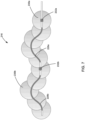
- FIG. 2 is a conceptual diagram illustrating an example configuration of distal portion 16 of implantable medical lead 10.
- the undulating configuration of distal portion 16 may include a plurality of peaks along the length of the distal portion.
- distal portion includes three peaks 24a, 24b, and 24c (collectively, "peaks 24").
- peaks 24 may include any number of peaks 24.
- the undulating configuration may define a peak-to-peak distance 35, which may be variable or constant along the length of distal portion 16.
- the undulating configuration defines a substantially sinusoidal configuration, with a constant peak-to-peak distance 35 of approximately 2.0-5.0 cm.
- the undulating configuration may also define a peak-to-peak width 37, which may also be variable or constant along the length of the undulating configuration.
- the undulating configuration defines a substantially sinusoidal shape, with a constant peak-to-peak width 37 of approximately 0.5-2.0 cm.
- the undulating configuration may define other shapes and/or patterns, e.g., S-shapes, wave shapes, or the like.
- Defibrillation electrodes 28 may extend along, e.g., be disposed on or cover, a substantial part of the undulating configuration of distal portion 16, e.g., along at least 80% of the undulating portion. Defibrillation electrodes 28 may extend along more or less than 80% of the undulating configuration. As another example, defibrillation electrodes 28 may extend along at least 90% of the undulating configuration.
- Defibrillation electrode 28a extends along a substantial portion of the undulating configuration of distal portion 16 from the proximal end to peak 24b, e.g., along a substantial portion of the first "wave" associated with peak 24a
- the defibrillation electrode segment 28b extends along a substantial portion of the undulating configuration from peak 24b to the distal end of the undulating configuration, e.g., along a substantial portion of the second "wave" associated with peak 24c).
- a part of the undulating configuration on which defibrillation electrodes 28 are not disposed is a gap between defibrillation electrodes 28a and 28b, on peak 24b, where electrode 32b is disposed.
- distal portion 16 of lead 10 may comprise a shield 30.
- shield 30 like pace/sense electrode 32b, is positioned between defibrillation electrodes 28a and 28b, e.g., on peak 24b of the undulating configuration of distal portion 16.
- Shield 30 covers or is otherwise disposed over a portion of an outer surface of pace/sense electrode 32b. Shield 30 does not cover an entirety of the outer surface of pace/sense electrode 32b.
- Pacing pulses delivered by ICD 9 via pace/sense electrode 32b result in an electrical field proximate the electrode, that "spreads" from the electrode surface toward one or more other electrodes used to deliver the pacing pulse.
- Shield 30 impedes the electrical field in directions from the electrode toward the shield, and allows the spread in directions from the electrode away from the shield. In this manner, shield 30 is configured to make pace/sense electrode 32b directional.
- shield 30 may extend laterally away from pace/sense electrode 32b, e.g., in a substantially planar manner, such that the dimensions of shield 30 in a plane are greater than those of pace/sense electrode 32b in the plane. In this manner, shield 30 may further (or more effectively) limit the directions, e.g., radial angles, of the spread of the electrical field generated by the pacing pulse from pace/sense electrode 32b.
- the plane in which shield 30 extends laterally from pace/sense electrode 32b may be the same plane in which peaks 24 of the undulating configuration extend, or a substantially parallel plane. In some examples, such as that illustrated by FIG.
- shield 30 extends symmetrically from pace/sense electrode 32b, e.g., is symmetrical about a longitudinal axis and/or a transverse axis of pace/sense electrode 32b, such that pace/sense electrode 32b is substantially centered within the outer profile of shield 30 in the plane.
- the portion of the outer surface of pace/sense electrode 32b over which shield 30 is positioned may be referred to as an "anterior portion" of the outer surface of pace/sense electrode 32b, since that portion of pace/sense electrode 32b may be more anteriorly positioned within the patient when distal portion 16 of lead 10 is implanted within patient.
- shield 30 With shield 30 positioned over an anterior portion of the outer surface of pace/sense electrode 32b, shield 30 may be positioned anteriorly relative to the central longitudinal axis of pace/sense electrode 32b. With shield 30 positioned over an anterior portion of the outer surface of pace/sense electrode 32b, and distal portion 16 implanted within the patient as illustrated in FIGS. 1A-1C , shield 30 may impede the electrical field in directions away from heart 26, referred to as anterior directions.
- Shield 30 may be electrically insulative.
- shield 30 comprises a polymer, such as polyurethane.
- shield 30 is configured to be folded or wrapped around pace/sense electrode 32b for delivery via a lumen of an implant tool, and configured to elastically unfold or unwrap to a relaxed condition, e.g., such as the condition shown in FIG. 2 , when released from the lumen.
- shield 30 comprises elastic or super-elastic polymer or metallic structures, e.g., Nitinol structures, to encourage the deployment of shield 30, support articulation of shield 30, and/or support shield 30 in the deployed, relaxed configuration.
- the deployed and/or articulated configuration may be substantially planar, as illustrated in FIG. 2 , or may be non-planar.
- portions of shield 30 spaced further away laterally from pace/sense electrode 32b may be situated more posteriorly than portions closer to the electrode, e.g., in the shape of a cup or bowl.
- Such support structures may be partially or fully embedded within a primary material of shield 30, or attached to one or more outer surfaces of shield 30.
- a support structure is located circumferentially around a perimeter of shield 30, e.g., spaced a greatest distance laterally from the shield.
- other support structure locations are possible.
- one or more support structures may extend in radial or lateral direction from the electrode, e.g., from near electrode to near a periphery of the shield.
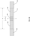
- FIGS. 3A-3C are conceptual diagrams illustrating views of shield 30 of implantable medical lead 10.
- FIG. 3A illustrates a "top" view in the anterior direction
- FIG. 3B illustrates a side view
- FIG. 3C a cross-sectional view taken at line A-A in FIG. 3B .
- shield 30 may extend from a distal end 41a of proximal defibrillation electrode 28a to a proximal end 41b of distal defibrillation electrode 28b in the direction of longitudinal axis "x" of distal portion 16. In some examples, shield 30 may extend over a portion or entirety of one or both of defibrillation electrodes 28. In some examples, shield 30 may not extend to one or both of defibrillation electrodes 28, leaving a gap between the shield and defibrillation electrode.
- FIGS. 3A and 3C illustrate shield 30 extending laterally away from pace/sense electrode 32b.
- shield 30 may be substantially circular in the plane in which the shield extends. In other examples, shield 30 may have other shapes, such as ovoid or rectangular.
- a length 44 of shield 30 is greater than a length 45 of pace/sense electrode 32b, such as at least twice the length of pace/sense electrode 32b.
- a width 46 of shield 30 is greater than a width 47 of pace/sense electrode 32b, such as at least twice width 47 of the pace electrode.
- shield 30 extends a distance 48 beyond pace/sense electrode 32b in the direction of its width, e.g., in a direction orthogonal to its longitudinal axis. In some examples, distance 48 is at least 5 mm, at least 7 mm, or at least 9 mm.
- One or both of length 44 and width 46 of shield 30 may be at least 15 mm, such as approximately 20 mm. In examples in which shield 30 is circular a dimeter of shield 30 may be at least 15 mm, such as approximately 20 mm.
- shield 30 includes a plurality of radiopaque markers, including radiopaque marker 42a and radiopaque marker 42b (collectively, "radiopaque markers 42").
- Shield 30 may include any number of radiopaque markers or no radiopaque markers.
- Radiopaque markers 42 may be distributed symmetrically on shield 30, e.g., relative to pace/sense electrode 32b.
- Radiopaque markers 42 may be positioned on shield 30 to allow a user to visualize at least one of a position or an orientation of the shield within the patient by identification of the radiopaque markers in a fluoroscopic or other image.
- Radiopaque markers 42 may be different from each other in one or more ways, e.g., size, shape, or orientation, to allow, for example, a physician to differentiate between radiopaque markers 42, in this way facilitating visualization of the orientation of shield 30.
- one of radiopaque markers 42 positioned on shield 30 may be larger than the rest such that the physician may determine, based on the position of the larger radiopaque marker (e.g., relative to the rest of radiopaque markers 42), the orientation of shield 30.
- distal portion 16 of lead 10 may include lead body portion 40a and lead body portion 40b (collectively, “lead body portions 40").
- Lead body portions 40 extend between pace/sense electrode 32b and a respective one of defibrillation electrodes 28.
- Lead body portions 40 may provide a relatively even or smooth surface transition between the outer profile of pace/sense electrode 32b and the outer profiles of defibrillation electrodes 28.
- Conductors coupled to electrodes 32b and 28b may extend through lead body portion 40a, and a conductor coupled to electrode 28b may extend through lead body portion 40b.
- Lead body portions 40a and 40b may formed of one or more polymers, which may be the same as or different from shield 30 and/or other portions of lead body 13.
- pace/sense electrode 32b may define a lumen 53, e.g., may be in the form of a ring, and a conductor coupled to electrode 28b may extend through lumen 53.
- pace/sense electrodes 32 may have other shapes, including partial or segmented ring shapes or arc shapes, in which one or more electrodes or electrode segments extend less than 360-degrees around a circumference of the lead.
- a depth 49 of shield 30 may be less than a depth 51 of pace/sense electrode 32b, such as less than one half of the depth of the electrode. Although illustrated as substantially constant, depth 49 of shield 30 may vary. For example, depth 49 may increase toward pace/sense electrode 32b and/or decrease toward an edge of the shield, e.g., to provide a smooth or otherwise desired transition between shield 30 and pace/sense electrode 32b and/or between shield 30 and tissue of the patient. Additionally, although defibrillation electrodes 28, pace/sense electrode 32b, and lead body portions 40a and 40b are shown in FIG.
- depth 49 of shield 30 may be similar to that of lead body portions 40a and 40b and pace/sense electrode 32b may extend outward from lead body portions 40a and 40b and shield 30, e.g., due to having a greater depth or being offset from a longitudinal axis defined by lead body portions 40a and 40b.
- pacing pulses delivered by ICD 9 via pace/sense electrode 32b result in an electrical field 55 proximate the electrode, that "spreads" from electrode outer surface 43.
- Shield 30 may reduce and/or impede the electrical field in directions from the electrode toward the shield, and allows the spread in directions from the electrode away from the shield. In this manner, shield 30 is configured to make pace/sense electrode 32b directional.
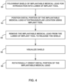
- FIG. 4 is a flow diagram illustrating an example technique for implanting an implantable medical lead comprising a shield.
- FIG. 4 is described with respect to implantable medical lead 10 and shield 30. However, the example technique of FIG. 4 may be used to implant other leads including one or more shields.
- a medical practitioner may implant distal portion 16 of implantable medical lead 10 into a substernal or other extravascular location using an implant tool.
- a medical practitioner or assistant may fold or wrap shield 30 around pace/sense electrode 32b, so that it may fit within a lumen (or a channel)of an implant tool, and introduce distal portion 16 of lead 10 into the lumen (50).
- distal portion 16 may be loaded into the lumen and packaged in a sterile package prior to the implantation procedure, e.g., by a manufacturer of lead 10 and/or the implant tool.
- the lumen of the implant tool may be cylindrical, or may otherwise have a profile that matches the outer profile of distal portion 16.
- the undulating configuration of distal portion 16 may be straightened when within the lumen.
- the lumen may comprise a sheath. Configurations other than those including a lumen of an implant tool for releasing shield 30 are contemplated by this disclosure.
- the medical practitioner may introduce the implant tool into the patient via a subxiphoid incision, and advance the implant tool to the extravascular location. Advancement of the tool to the extravascular location may occur before or after lead 10 is loaded into the tool. In either case, distal portion 16 of lead 10 is positioned at the extravascular location using the implant tool, e.g., by advancement through the lumen or advancement of the tool while in the lumen (52).
- the implant tool may include a tunneling tool having a rod or other tunneling member and a sheath configured to be placed on the rod.
- the medical practitioner removes distal portion 16 of lead 10 from the implant tool to release the shield (54).
- the medical practitioner may release the shield by withdrawing the sheath proximally from the patient and/or splitting the sheath.
- the implant tool or the sheath of the implant tool may be formed to have a channel or other recessed portion accessible via a longitudinal opening to receive distal portion 16 of lead 10 including shield 30 and the medical practitioner may release the shield by laterally separating distal portion 16 of lead 10 from the channel or other recessed portion of the sheath or implant tool.
- shield 30 When shield 30 is free from the lumen, shield 30 may transition from the folded or wrapped configuration to a deployed configuration, e.g., may be elastically deformed to the folded or wrapped configuration and release to the deployed configuration, which may be a relaxed configuration.
- lead 10 may include a fluid, balloon, spring or other actuatable mechanism to transition shield 30 to the deployed configuration.
- the medical practitioner may visualize shield 30 within patient, e.g., using fluoroscopy or other medical imaging to identify radiopaque markers (56).
- the medical practitioner may, if necessary, rotationally orient distal portion 16 of lead 10 so that shield 30 is positioned anteriorly relative to pace/sense electrode 32b (58).
- FIG. 5 is a flow diagram illustrating an example technique for manufacturing an implantable medical lead comprising a shield.
- FIG. 5 is described with respect to implantable medical lead 10 and shield 30. However, the example technique of FIG. 5 may be used to implant other leads including one or more shields.
- shield 30 is attached to an anterior portion of surface 43 of pace/sense electrode 32b (60).
- shield 30 is a separately molded element that is attached to pace/sense electrode 32b using an adhesive.
- shield 30 is molded onto pace/sense electrode 32b.
- the molding of shield 30 onto pace/sense electrode 32b further includes molding lead body portion 40a to a proximal end of pace/sense electrode 32b and lead body portion 40b to a distal end of pace/sense electrode 32b, e.g., shield 30 and lead body portions 40 may be molded as a single piece of a common material.
- Pace/sense electrode 32b and shield 30 may then be assembled onto lead 10 as a unit (62).
- Lead 10 may then optionally be overmolded (64).
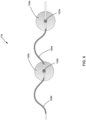
- FIG. 6 is a conceptual diagram illustrating a distal portion 116 of an example implantable medical lead comprising a plurality of shields.
- Distal portion 116 is similar to distal portion 16 of lead 10, and like numbered elements of distal portion 116 are similar to those of distal portion 16.
- distal portion 116 includes defibrillation electrodes 128a and 128b and pace/sense electrodes 132a and 132b, and defines an undulating configuration similar to distal portion 16.
- distal portion 116 includes a first shield 130a over an anterior portion of a surface of pace/sense electrode 132a and a second shield 130b over an anterior portion of a surface of pace/sense electrode 132b.
- Shield 130a and shield 130b may be the same as or different than each other.
- each of shields 130a and 130b may be the same as or substantially similar to shield 30 described herein with respect to FIGS. 1-5 , e.g., may include any combination of one or more of the features described above with respect to shield 30.
- FIG. 7 is a conceptual diagram illustrating a distal portion 216 of another example implantable medical lead comprising a plurality of shields.
- Distal portion 216 is similar to distal portion 16 of lead 10, and like numbered elements of distal portion 216 are similar to those of distal portion 16.
- distal portion 216 includes defibrillation electrodes 228a and 228b and pace/sense electrodes 232a and 232b, and defines an undulating configuration similar to distal portion 16.
- distal portion 216 includes a plurality of shields including labeled shields 230a and 230b (collectively, "shields 230").
- Shields 230 may be the same as or different than each other.
- each of shields 230 may be the same as or substantially similar to shield 30 described herein with respect to FIGS. 1-5 , e.g., may include any combination of one or more of the features described above with respect to shield 30.
- shields 230 may collectively cover an anterior portion of an outer surface for each of electrodes 228 and 232.
- defibrillation electrodes 228 may be used to deliver pacing pulses, and shields 230 may provide the same directionality of electrical fields proximate defibrillation electrodes 228 as described with respect to pace sense electrodes 232.
- Use of a plurality of shields 230 arranged as illustrated in FIG. 7 may provide directionality of electrical fields, while allowing distal portion 216 to be straightened for implantation and then assume the illustrated undulating configuration when implanted.
- FIG. 8 is a conceptual diagram illustrating a distal portion 316 of another example implantable medical lead comprising a shield.
- distal portion 316 includes defibrillation electrodes 328a and 328b, pace/sense electrodes 332a and 332b.
- distal portion 316 defines a straight or substantially straight configuration, rather than an undulating configuration.
- distal portion 316 includes a single shield 330 that covers an anterior portion of an outer surface for each of electrodes 228 and 232.
- Shield 330 may be the same as or substantially similar to shield 30 described herein with respect to FIGS. 1-5 , e.g., may include any combination of one or more of the features described above with respect to shield 30.
- any the shields described herein may be included as part of differently configured implantable medical leads.
- some implantable medical leads may include a single defibrillation electrode and one or more pace/sense electrodes located distal and/or proximal of the defibrillation electrode.
- an implantable medical lead that includes one or more stimulation electrodes, not necessarily for cardiac pacing does not include a defibrillation electrode.
- one or more shields configured as described herein may be located over a portion of a surface of one or more electrodes.
- FIG. 9 is a conceptual diagram illustrating part of a distal portion 516 of another implantable medical lead comprising a shield.
- Distal portion 516 may be similar to distal portion 16 of lead 10, and like numbered elements of distal portion 516 may be similar to those of distal portion 16.
- distal portion 516 includes defibrillation electrodes 528a and 528b (collectively, “defibrillation electrodes 528") and pace/sense electrode 532.
- Distal portion 516 also includes a lead body portion 540 extending from defibrillation electrode 528a to defibrillation electrode 528b.
- Lead body portion 540 may provide a relatively even or smooth surface transition between the outer profiles of defibrillation electrodes 528.
- Lead body portion 540 may be formed of an insulative material and conductors coupled to electrodes 532 and 528b may extend through lead body portion 540.
- pace/sense electrode 532 is located within a recessed portion 570 of lead body portion 540.
- Lead body portion 540 having recessed portion 570 may cover an anterior portion of a surface of pace/sense electrode 532 and impede an electrical field in at least an anterior direction.
- distal portion 516 may further include a shield 30 or any other shield as described herein over the anterior portion of the surface of pace/sense electrode 532 to impede the electrical field in the anterior direction.
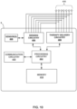
- FIG. 10 is a functional block diagram of an example configuration of electronic components and other components of ICD 9.
- ICD 9 includes a processing circuitry 402, sensing circuitry 404, therapy delivery circuitry 406, sensors 408, communication circuitry 410, and memory 412.
- ICD 9 may include more or fewer components.
- the described circuitry and other components may be implemented together on a common hardware component or separately as discrete but interoperable hardware or software components. Depiction of different features is intended to highlight different functional aspects and does not necessarily imply that such circuitry and other components must be realized by separate hardware or software components. Rather, functionality associated with one or more circuitries and components may be performed by separate hardware or software components, or integrated within common or separate hardware or software components.
- Sensing circuitry 404 may be electrically coupled to some or all of electrodes 416, which may correspond to any of the defibrillation, pace/sense, and housing electrodes described herein. Sensing circuitry 404 is configured to obtain signals sensed via one or more combinations of electrodes 416 and process the obtained signals.
- sensing circuitry 404 may be analog components, digital components or a combination thereof.
- Sensing circuitry 404 may, for example, include one or more sense amplifiers, filters, rectifiers, threshold detectors, analog-to-digital converters (ADCs) or the like.
- Sensing circuitry 404 may convert the sensed signals to digital form and provide the digital signals to processing circuitry 402 for processing or analysis.
- sensing circuitry 404 may amplify signals from the sensing electrodes and convert the amplified signals to multi-bit digital signals by an ADC.
- Sensing circuitry 404 may also compare processed signals to a threshold to detect the existence of atrial or ventricular depolarizations (e.g., P- or R waves) and indicate the existence of the atrial depolarization (e.g., P-waves) or ventricular depolarizations (e.g., R-waves) to processing circuitry 402.
- ICD 9 may additionally include one or more sensors 408, such as one or more accelerometers, which may be configured to provide signals indicative of other parameters of a patient, such as activity or posture, to processing circuitry 402.
- Processing circuitry 402 may process the signals from sensing circuitry 404 to monitor electrical activity of heart 26 of patient 12. Processing circuitry 402 may store signals obtained by sensing circuitry 404 as well as any generated EGM waveforms, marker channel data or other data derived based on the sensed signals in memory 412. Processing circuitry 402 may analyze the EGM waveforms and/or marker channel data to detect arrhythmias (e.g., bradycardia or tachycardia). In response to detecting the cardiac event, processing circuitry 402 may control therapy delivery circuitry 406 to deliver the desired therapy to treat the cardiac event, e.g., defibrillation shock, cardioversion shock, ATP, post shock pacing, or bradycardia pacing.
- arrhythmias e.g., bradycardia or tachycardia
- processing circuitry 402 may control therapy delivery circuitry 406 to deliver the desired therapy to treat the cardiac event, e.g., defibrillation shock, cardioversion
- Therapy delivery circuitry 406 is configured to generate and deliver electrical therapy to heart 26.
- Therapy delivery circuitry 406 may include one or more pulse generators, capacitors, and/or other components capable of generating and/or storing energy to deliver as pacing therapy, defibrillation therapy, cardioversion therapy, cardiac resynchronization therapy, other therapy or a combination of therapies.
- therapy delivery circuitry 406 may include a first set of components configured to provide pacing therapy and a second set of components configured to provide defibrillation therapy. In other instances, therapy delivery circuitry 406 may utilize the same set of components to provide both pacing and defibrillation therapy.
- therapy delivery circuitry 406 may share some of the defibrillation and pacing therapy components while using other components solely for defibrillation or pacing.
- Processing circuitry 402 may control therapy delivery circuitry 406 to deliver the generated therapy to heart 26 via one or more combinations of electrodes 416.
- ICD 9 may include switching circuitry configurable by processing circuitry 402 to control which of electrodes 416 is connected to therapy delivery circuitry 406 and sensing circuitry 404.
- Communication circuitry 410 includes any suitable hardware, firmware, software or any combination thereof for communicating with another device, such as a clinician programmer, a patient monitoring device, or the like.
- communication circuitry 410 may include appropriate modulation, demodulation, frequency conversion, filtering, and amplifier components for transmission and reception of data with the aid of an antenna.
- ICD 9 may include any one or more processors, controllers, digital signal processors (DSPs), application specific integrated circuits (ASICs), field-programmable gate arrays (FPGAs), or equivalent discrete or integrated circuitry, including analog circuitry, digital circuitry, or logic circuitry.
- DSPs digital signal processors
- ASICs application specific integrated circuits
- FPGAs field-programmable gate arrays
- Processing circuitry 402 may include fixed function circuitry and/or programmable processing circuitry.
- the functions attributed to processing circuitry 402 herein may be embodied as software, firmware, hardware or any combination thereof.
- Memory 412 may include computer-readable instructions that, when executed by processing circuitry 402 or other components of ICD 9, cause one or more components of ICD 9 to perform various functions attributed to those components in this disclosure.
- Memory 412 may include any volatile, non-volatile, magnetic, optical, or electrical media, such as a random-access memory (RAM), read-only memory (ROM), non-volatile RAM (NVRAM), static non-volatile RAM (SRAM), electrically-erasable programmable ROM (EEPROM), flash memory, or any other non-transitory computer-readable storage media.
- RAM random-access memory
- ROM read-only memory
- NVRAM non-volatile RAM
- SRAM static non-volatile RAM
- EEPROM electrically-erasable programmable ROM
- flash memory or any other non-transitory computer-readable storage media.
- the leads and systems described herein may be used at least partially within the substernal space, e.g., within anterior mediastinum of patient, to provide an extravascular ICD system.
- An implanter e.g., physician
- implanter may create an incision near the center of the torso of the patient, e.g., and introduce the implant tool into the substernal location via the incision.
- the implant tool is advanced from the incision superior along the posterior of the sternum in the substernal location.
- the distal portion of the lead is introduced into the tunnel via implant tool (e.g., via a sheath). As the distal portion is advanced through the substernal tunnel, the distal portion is relatively straight.
- the pre-formed or shaped undulating configuration is flexible enough to be straightened out while routing the lead through a sheath or other lumen or channel of the implant tool.
- the implant tool is withdrawn toward the incision and removed from the body of the patient while leaving the lead in place along the substernal path. As the implant tool is withdrawn, the distal end of the lead takes on its pre-formed undulating configuration, and the shield transitions to its deployed configuration.
- the distal portion of the lead may be oriented orthogonal or otherwise transverse to the sternum and/or inferior to the heart.
- the lead may include one or more shields that cover a portion of an outer surface of one or more electrodes, e.g., an anterior and/or inferior portion, according to any of the examples described herein. Such shield(s) may impede an electrical field in a direction away from the heart, which may be an anterior and/or inferior direction.
Landscapes
- Health & Medical Sciences (AREA)
- Cardiology (AREA)
- Life Sciences & Earth Sciences (AREA)
- Animal Behavior & Ethology (AREA)
- Biomedical Technology (AREA)
- Nuclear Medicine, Radiotherapy & Molecular Imaging (AREA)
- Radiology & Medical Imaging (AREA)
- Engineering & Computer Science (AREA)
- General Health & Medical Sciences (AREA)
- Public Health (AREA)
- Veterinary Medicine (AREA)
- Heart & Thoracic Surgery (AREA)
- Biophysics (AREA)
- Neurosurgery (AREA)
- Neurology (AREA)
- Electrotherapy Devices (AREA)
Claims (15)
- Sonde médicale implantable (10) comprenant :une première électrode de défibrillation (28) et une deuxième électrode de défibrillation (28), les première et deuxième électrodes de défibrillation étant configurées pour délivrer des chocs anti-tachyarythmie ;une électrode de stimulation (32) disposée entre la première électrode de défibrillation et la deuxième électrode de défibrillation, l'électrode de stimulation étant configurée pour délivrer une impulsion de stimulation qui génère un champ électrique à proximité de l'électrode de stimulation ; etun blindage (30) disposé entre la première électrode de défibrillation et la deuxième électrode de défibrillation, sur une partie d'une surface extérieure de l'électrode de stimulation, et s'étendant latéralement à l'écart de l'électrode de stimulation, caractérisé en ce que le blindage est configuré pour empêcher le champ électrique dans une direction s'éloignant de l'électrode de stimulation et du cœur (26).
- Sonde médicale implantable selon la revendication 1, dans laquelle la longueur (44) du blindage est supérieure à la longueur (45) de l'électrode de stimulation.
- Sonde médicale implantable selon la revendication 1 ou la revendication 2, dans laquelle le blindage s'étend depuis une extrémité distale d'une électrode de défibrillation proximale parmi la première électrode de défibrillation et la deuxième électrode de défibrillation jusqu'à une extrémité proximale d'une électrode de défibrillation distale parmi la première électrode de défibrillation et la deuxième électrode de défibrillation.
- Sonde médicale implantable selon l'une quelconque des revendications 1 à 3, dans laquelle la largeur (46) du blindage est supérieure à la largeur (47) de l'électrode de stimulation.
- Sonde médicale implantable selon l'une quelconque des revendications 1 à 4, dans laquelle le blindage est électriquement isolant.
- Sonde médicale implantable selon l'une quelconque des revendications 1 à 5, dans laquelle le blindage est configuré pour être plié ou enroulé autour de l'électrode de stimulation afin d'être délivré par la lumière d'un outil d'implantation, et configuré pour se déplier ou se dérouler de manière élastique afin d'adopter une configuration ouverte lorsqu'il est libéré de la lumière.
- Sonde médicale implantable selon l'une quelconque des revendications 1 à 6,dans laquelle la partie distale de la sonde médicale implantable définit une configuration ondulée comprenant un premier pic s'étendant dans une première direction, un deuxième pic s'étendant dans la première direction, et un troisième pic, entre le premier pic et le deuxième pic, s'étendant dans une deuxième direction opposée à la première direction, etdans laquelle au moins une partie de la première électrode de défibrillation est disposée sur le premier pic, au moins une partie de la deuxième électrode de défibrillation est disposée sur le deuxième pic, et au moins une partie de l'électrode de stimulation est disposée sur le troisième pic.
- Sonde médicale implantable selon l'une quelconque des revendications 1 à 7, dans laquelle le blindage comprend au moins une structure de support configurée pour faciliter le déploiement et/ou l'articulation du blindage.
- Sonde médicale implantable selon la revendication 8, dans laquelle la structure de support comprend du Nitinol.
- Sonde médicale implantable selon l'une quelconque des revendications 1 à 9, comprenant en outre une partie de corps de sonde comprenant un évidement (570), où l'électrode de stimulation est encastrée dans l'évidement de la partie de corps de conducteur.
- Sonde médicale implantable selon l'une quelconque des revendications 1 à 10, dans lequel l'électrode de stimulation comprend une première électrode de stimulation et le blindage comprend un premier blindage, la sonde médicale implantable comprenant :une deuxième électrode de stimulation ; etun deuxième blindage disposé sur une partie d'une surface extérieure de la deuxième électrode de stimulation et s'étendant latéralement à partir de la deuxième électrode de stimulation, où le deuxième blindage est configuré pour empêcher le champ électrique dans une direction s'éloignant de la deuxième électrode de stimulation et du cœur.
- Sonde médicale implantable selon l'une quelconque des revendications 1 à 11, comprenant en outre une pluralité de blindages répartis sur une longueur de la partie distale de la sonde médicale implantable.
- Sonde médicale implantable selon l'une quelconque des revendications 1 à 12, dans laquelle la partie de la surface de l'électrode de stimulation est une partie inférieure, et le blindage est configuré pour empêcher le champ électrique dans une direction inférieure à partir de l'électrode de stimulation.
- Système médical implantable (8) comprenant :
un dispositif médical implantable comprenant :un logement (9) ; etdes circuits de délivrance de soin (406) à l'intérieur du logement et configurés pour générer des chocs anti-tachyarythmie et une impulsion de stimulation ; etla sonde médicale implantable selon l'une quelconque des revendications 1 à 13. - Procédé de fabrication de la sonde médicale implantable selon l'une quelconque des revendications 1 à 14, le procédé comprenant les étapes suivantes :fixer un blindage à la surface d'une électrode de stimulation, où l'électrode de stimulation est configurée pour délivrer une impulsion de stimulation qui génère un champ électrique à proximité de l'électrode de stimulation, et où le blindage est configuré pour empêcher le champ électrique dans une direction s'éloignant de l'électrode de stimulation ; etassembler ensuite le blindage et l'électrode de stimulation sur la sonde médicale implantable comprenant une première électrode de défibrillation et une deuxième électrode de défibrillation, les première et deuxième électrodes de défibrillation étant configurées pour délivrer des chocs anti-tachyarythmie, l'électrode de stimulation étant assemblée de telle sorte que l'électrode de stimulation soit disposée entre la première électrode de défibrillation et la deuxième électrode de défibrillation, le blindage étant assemblé de telle sorte que le blindage soit disposé entre la première électrode de défibrillation et la deuxième électrode de défibrillation, sur une partie d'une surface extérieure de l'électrode de stimulation, et s'étendant latéralement à l'écart de l'électrode de stimulation, et le blindage étant configuré pour empêcher le champ électrique dans une direction s'éloignant de l'électrode de stimulation et s'éloignant d'un cœur.
Applications Claiming Priority (3)
| Application Number | Priority Date | Filing Date | Title |
|---|---|---|---|
| US202062982790P | 2020-02-28 | 2020-02-28 | |
| US17/185,784 US12186572B2 (en) | 2020-02-28 | 2021-02-25 | Implantable medical lead with shield |
| PCT/US2021/020041 WO2021174093A1 (fr) | 2020-02-28 | 2021-02-26 | Fil médical implantable avec blindage |
Publications (2)
| Publication Number | Publication Date |
|---|---|
| EP4110457A1 EP4110457A1 (fr) | 2023-01-04 |
| EP4110457B1 true EP4110457B1 (fr) | 2025-06-18 |
Family
ID=77463893
Family Applications (1)
| Application Number | Title | Priority Date | Filing Date |
|---|---|---|---|
| EP21714467.4A Active EP4110457B1 (fr) | 2020-02-28 | 2021-02-26 | Fil médical implantable avec blindage |
Country Status (4)
| Country | Link |
|---|---|
| US (1) | US12186572B2 (fr) |
| EP (1) | EP4110457B1 (fr) |
| CN (1) | CN115151301A (fr) |
| WO (1) | WO2021174093A1 (fr) |
Families Citing this family (5)
| Publication number | Priority date | Publication date | Assignee | Title |
|---|---|---|---|---|
| US12472369B2 (en) * | 2021-12-20 | 2025-11-18 | Medtronic, Inc. | Implantable medical lead shield |
| WO2023173085A1 (fr) * | 2022-03-11 | 2023-09-14 | Medtronic, Inc. | Fil médical implantable avec blindage |
| EP4489842A1 (fr) * | 2022-03-11 | 2025-01-15 | Medtronic, Inc. | Fil médical implantable avec blindage |
| CN118984726A (zh) * | 2022-03-11 | 2024-11-19 | 美敦力公司 | 具有屏蔽件的植入式医疗引线 |
| CN119403597A (zh) * | 2022-07-01 | 2025-02-07 | 美敦力公司 | 临时起搏导联导航系统 |
Citations (1)
| Publication number | Priority date | Publication date | Assignee | Title |
|---|---|---|---|---|
| US20070239244A1 (en) * | 2006-04-11 | 2007-10-11 | Pacesetter, Inc. | Intrapericardial lead |
Family Cites Families (26)
| Publication number | Priority date | Publication date | Assignee | Title |
|---|---|---|---|---|
| US4257424A (en) | 1979-04-30 | 1981-03-24 | Ndm Corporation | X-ray transparent medical electrode |
| DK152086C (da) | 1982-02-15 | 1988-06-20 | Medicotest Systemer As | Hudelektrode og fremgangsmaade ved fremstilling deraf |
| US4870969A (en) | 1988-09-16 | 1989-10-03 | Somatics, Inc. | Electrode application system and method for electroconvulsive therapy |
| US5477855A (en) | 1993-07-16 | 1995-12-26 | Alfred E. Mann Foundation For Scientific Research | Shield for conductors of an implantable device |
| US5897554A (en) | 1997-03-01 | 1999-04-27 | Irvine Biomedical, Inc. | Steerable catheter having a loop electrode |
| US6330481B1 (en) | 1999-10-04 | 2001-12-11 | Medtronic Inc. | Temporary medical electrical lead having biodegradable electrode mounting pad |
| US20020035381A1 (en) | 2000-09-18 | 2002-03-21 | Cameron Health, Inc. | Subcutaneous electrode with improved contact shape for transthoracic conduction |
| US7862563B1 (en) | 2005-02-18 | 2011-01-04 | Cosman Eric R | Integral high frequency electrode |
| WO2008034077A2 (fr) * | 2006-09-15 | 2008-03-20 | Cardiac Pacemakers, Inc. | Ancrage pour capteur implantable |
| US7769457B2 (en) * | 2007-08-04 | 2010-08-03 | Cameron Health, Inc. | Electromagnetic interference shielding in an implantable medical device |
| US20100036466A1 (en) | 2008-08-11 | 2010-02-11 | Pacesetter, Inc. | Lead construction with composite material shield layer |
| US8364281B2 (en) * | 2008-11-07 | 2013-01-29 | W. L. Gore & Associates, Inc. | Implantable lead |
| EP3231476B1 (fr) | 2008-11-12 | 2019-06-19 | Ecole Polytechnique Fédérale de Lausanne | Dispositif de neurostimulation microfabriqué |
| WO2010126877A1 (fr) | 2009-04-30 | 2010-11-04 | Medtronic, Inc. | Protection d'une dérivation médicale implantable |
| US9974944B2 (en) | 2010-07-29 | 2018-05-22 | Cameron Health, Inc. | Subcutaneous leads and methods of implant and explant |
| JP2014521400A (ja) * | 2011-07-07 | 2014-08-28 | カーディアック ペースメイカーズ, インコーポレイテッド | 植え込み型医療装置リード用の絶縁および安定機構 |
| US10556117B2 (en) * | 2013-05-06 | 2020-02-11 | Medtronic, Inc. | Implantable cardioverter-defibrillator (ICD) system including substernal pacing lead |
| US20140330287A1 (en) | 2013-05-06 | 2014-11-06 | Medtronic, Inc. | Devices and techniques for anchoring an implantable medical device |
| US9610436B2 (en) | 2013-11-12 | 2017-04-04 | Medtronic, Inc. | Implant tools with attachment feature and multi-positional sheath and implant techniques utilizing such tools |
| US10675478B2 (en) * | 2014-12-09 | 2020-06-09 | Medtronic, Inc. | Extravascular implantable electrical lead having undulating configuration |
| EP3064131A1 (fr) | 2015-03-03 | 2016-09-07 | BIOTRONIK SE & Co. KG | Appareil de stimulation du nerf vague-phrénique combiné |
| CN109414579A (zh) | 2016-05-03 | 2019-03-01 | 纽佩斯公司 | 柔性半封闭植入式医疗设备结构 |
| US10463295B2 (en) | 2016-06-13 | 2019-11-05 | Medtronic, Inc. | Multi-parameter prediction of acute cardiac episodes and attacks |
| CN109562271B (zh) | 2016-08-05 | 2023-01-13 | 心脏起搏器股份公司 | 使用胸廓内脉管系统的有源医疗装置植入 |
| WO2018093594A1 (fr) * | 2016-11-17 | 2018-05-24 | Cardiac Pacemakers, Inc. | Électrode de défibrillateur cardioverteur implantable sous la peau directionnelle |
| GB201806115D0 (en) | 2018-04-13 | 2018-05-30 | Lau Ernest Wai Yin | A lead anchor device and method of use |
-
2021
- 2021-02-25 US US17/185,784 patent/US12186572B2/en active Active
- 2021-02-26 CN CN202180016921.5A patent/CN115151301A/zh active Pending
- 2021-02-26 EP EP21714467.4A patent/EP4110457B1/fr active Active
- 2021-02-26 WO PCT/US2021/020041 patent/WO2021174093A1/fr not_active Ceased
Patent Citations (1)
| Publication number | Priority date | Publication date | Assignee | Title |
|---|---|---|---|---|
| US20070239244A1 (en) * | 2006-04-11 | 2007-10-11 | Pacesetter, Inc. | Intrapericardial lead |
Also Published As
| Publication number | Publication date |
|---|---|
| EP4110457A1 (fr) | 2023-01-04 |
| US20210268297A1 (en) | 2021-09-02 |
| US12186572B2 (en) | 2025-01-07 |
| CN115151301A (zh) | 2022-10-04 |
| WO2021174093A1 (fr) | 2021-09-02 |
Similar Documents
| Publication | Publication Date | Title |
|---|---|---|
| US12447331B2 (en) | Extravascular implantable electrical lead having undulating configuration | |
| EP4110457B1 (fr) | Fil médical implantable avec blindage | |
| US10058695B2 (en) | Collapsible extravascular lead | |
| US12472369B2 (en) | Implantable medical lead shield | |
| US20250144433A1 (en) | Implantable medical lead with shield | |
| EP4489843B1 (fr) | Fil médical implantable avec blindage | |
| US20250186788A1 (en) | Implantable medical lead with shield | |
| US20250352812A1 (en) | Implantable medical lead implant tool | |
| EP4561670A1 (fr) | Fil électrique médical implantable pour stimulation électrique extravasculaire | |
| EP4608495A1 (fr) | Agencement d'électrodes multiples pour thérapie |
Legal Events
| Date | Code | Title | Description |
|---|---|---|---|
| STAA | Information on the status of an ep patent application or granted ep patent |
Free format text: STATUS: UNKNOWN |
|
| STAA | Information on the status of an ep patent application or granted ep patent |
Free format text: STATUS: THE INTERNATIONAL PUBLICATION HAS BEEN MADE |
|
| PUAI | Public reference made under article 153(3) epc to a published international application that has entered the european phase |
Free format text: ORIGINAL CODE: 0009012 |
|
| STAA | Information on the status of an ep patent application or granted ep patent |
Free format text: STATUS: REQUEST FOR EXAMINATION WAS MADE |
|
| 17P | Request for examination filed |
Effective date: 20220812 |
|
| AK | Designated contracting states |
Kind code of ref document: A1 Designated state(s): AL AT BE BG CH CY CZ DE DK EE ES FI FR GB GR HR HU IE IS IT LI LT LU LV MC MK MT NL NO PL PT RO RS SE SI SK SM TR |
|
| DAV | Request for validation of the european patent (deleted) | ||
| DAX | Request for extension of the european patent (deleted) | ||
| STAA | Information on the status of an ep patent application or granted ep patent |
Free format text: STATUS: EXAMINATION IS IN PROGRESS |
|
| 17Q | First examination report despatched |
Effective date: 20240216 |
|
| GRAP | Despatch of communication of intention to grant a patent |
Free format text: ORIGINAL CODE: EPIDOSNIGR1 |
|
| STAA | Information on the status of an ep patent application or granted ep patent |
Free format text: STATUS: GRANT OF PATENT IS INTENDED |
|
| RIC1 | Information provided on ipc code assigned before grant |
Ipc: A61N 1/375 20060101ALI20250206BHEP Ipc: A61N 1/05 20060101ALI20250206BHEP Ipc: A61N 1/362 20060101ALI20250206BHEP Ipc: A61N 1/39 20060101AFI20250206BHEP |
|
| INTG | Intention to grant announced |
Effective date: 20250219 |
|
| GRAS | Grant fee paid |
Free format text: ORIGINAL CODE: EPIDOSNIGR3 |
|
| GRAA | (expected) grant |
Free format text: ORIGINAL CODE: 0009210 |
|
| STAA | Information on the status of an ep patent application or granted ep patent |
Free format text: STATUS: THE PATENT HAS BEEN GRANTED |
|
| AK | Designated contracting states |
Kind code of ref document: B1 Designated state(s): AL AT BE BG CH CY CZ DE DK EE ES FI FR GB GR HR HU IE IS IT LI LT LU LV MC MK MT NL NO PL PT RO RS SE SI SK SM TR |
|
| REG | Reference to a national code |
Ref country code: GB Ref legal event code: FG4D |
|
| REG | Reference to a national code |
Ref country code: CH Ref legal event code: EP |
|
| REG | Reference to a national code |
Ref country code: DE Ref legal event code: R096 Ref document number: 602021032439 Country of ref document: DE |
|
| REG | Reference to a national code |
Ref country code: CH Ref legal event code: EP |
|
| REG | Reference to a national code |
Ref country code: IE Ref legal event code: FG4D |
|
| PG25 | Lapsed in a contracting state [announced via postgrant information from national office to epo] |
Ref country code: FI Free format text: LAPSE BECAUSE OF FAILURE TO SUBMIT A TRANSLATION OF THE DESCRIPTION OR TO PAY THE FEE WITHIN THE PRESCRIBED TIME-LIMIT Effective date: 20250618 |
|
| REG | Reference to a national code |
Ref country code: LT Ref legal event code: MG9D |
|
| PG25 | Lapsed in a contracting state [announced via postgrant information from national office to epo] |
Ref country code: NO Free format text: LAPSE BECAUSE OF FAILURE TO SUBMIT A TRANSLATION OF THE DESCRIPTION OR TO PAY THE FEE WITHIN THE PRESCRIBED TIME-LIMIT Effective date: 20250918 Ref country code: GR Free format text: LAPSE BECAUSE OF FAILURE TO SUBMIT A TRANSLATION OF THE DESCRIPTION OR TO PAY THE FEE WITHIN THE PRESCRIBED TIME-LIMIT Effective date: 20250919 |
|
| PG25 | Lapsed in a contracting state [announced via postgrant information from national office to epo] |
Ref country code: BG Free format text: LAPSE BECAUSE OF FAILURE TO SUBMIT A TRANSLATION OF THE DESCRIPTION OR TO PAY THE FEE WITHIN THE PRESCRIBED TIME-LIMIT Effective date: 20250618 |
|
| PG25 | Lapsed in a contracting state [announced via postgrant information from national office to epo] |
Ref country code: HR Free format text: LAPSE BECAUSE OF FAILURE TO SUBMIT A TRANSLATION OF THE DESCRIPTION OR TO PAY THE FEE WITHIN THE PRESCRIBED TIME-LIMIT Effective date: 20250618 |
|
| PG25 | Lapsed in a contracting state [announced via postgrant information from national office to epo] |
Ref country code: RS Free format text: LAPSE BECAUSE OF FAILURE TO SUBMIT A TRANSLATION OF THE DESCRIPTION OR TO PAY THE FEE WITHIN THE PRESCRIBED TIME-LIMIT Effective date: 20250918 |
|
| REG | Reference to a national code |
Ref country code: NL Ref legal event code: MP Effective date: 20250618 |
|
| PG25 | Lapsed in a contracting state [announced via postgrant information from national office to epo] |
Ref country code: LV Free format text: LAPSE BECAUSE OF FAILURE TO SUBMIT A TRANSLATION OF THE DESCRIPTION OR TO PAY THE FEE WITHIN THE PRESCRIBED TIME-LIMIT Effective date: 20250618 |
|
| PG25 | Lapsed in a contracting state [announced via postgrant information from national office to epo] |
Ref country code: NL Free format text: LAPSE BECAUSE OF FAILURE TO SUBMIT A TRANSLATION OF THE DESCRIPTION OR TO PAY THE FEE WITHIN THE PRESCRIBED TIME-LIMIT Effective date: 20250618 |
|
| PG25 | Lapsed in a contracting state [announced via postgrant information from national office to epo] |
Ref country code: PT Free format text: LAPSE BECAUSE OF FAILURE TO SUBMIT A TRANSLATION OF THE DESCRIPTION OR TO PAY THE FEE WITHIN THE PRESCRIBED TIME-LIMIT Effective date: 20251020 |
|
| REG | Reference to a national code |
Ref country code: AT Ref legal event code: MK05 Ref document number: 1803678 Country of ref document: AT Kind code of ref document: T Effective date: 20250618 |
|
| PG25 | Lapsed in a contracting state [announced via postgrant information from national office to epo] |
Ref country code: IS Free format text: LAPSE BECAUSE OF FAILURE TO SUBMIT A TRANSLATION OF THE DESCRIPTION OR TO PAY THE FEE WITHIN THE PRESCRIBED TIME-LIMIT Effective date: 20251018 |
|
| PG25 | Lapsed in a contracting state [announced via postgrant information from national office to epo] |
Ref country code: AT Free format text: LAPSE BECAUSE OF FAILURE TO SUBMIT A TRANSLATION OF THE DESCRIPTION OR TO PAY THE FEE WITHIN THE PRESCRIBED TIME-LIMIT Effective date: 20250618 Ref country code: SM Free format text: LAPSE BECAUSE OF FAILURE TO SUBMIT A TRANSLATION OF THE DESCRIPTION OR TO PAY THE FEE WITHIN THE PRESCRIBED TIME-LIMIT Effective date: 20250618 |
|
| PG25 | Lapsed in a contracting state [announced via postgrant information from national office to epo] |
Ref country code: CZ Free format text: LAPSE BECAUSE OF FAILURE TO SUBMIT A TRANSLATION OF THE DESCRIPTION OR TO PAY THE FEE WITHIN THE PRESCRIBED TIME-LIMIT Effective date: 20250618 |
|
| PG25 | Lapsed in a contracting state [announced via postgrant information from national office to epo] |
Ref country code: PL Free format text: LAPSE BECAUSE OF FAILURE TO SUBMIT A TRANSLATION OF THE DESCRIPTION OR TO PAY THE FEE WITHIN THE PRESCRIBED TIME-LIMIT Effective date: 20250618 |
|
| PG25 | Lapsed in a contracting state [announced via postgrant information from national office to epo] |
Ref country code: EE Free format text: LAPSE BECAUSE OF FAILURE TO SUBMIT A TRANSLATION OF THE DESCRIPTION OR TO PAY THE FEE WITHIN THE PRESCRIBED TIME-LIMIT Effective date: 20250618 |
|
| PG25 | Lapsed in a contracting state [announced via postgrant information from national office to epo] |
Ref country code: SK Free format text: LAPSE BECAUSE OF FAILURE TO SUBMIT A TRANSLATION OF THE DESCRIPTION OR TO PAY THE FEE WITHIN THE PRESCRIBED TIME-LIMIT Effective date: 20250618 |
|
| PG25 | Lapsed in a contracting state [announced via postgrant information from national office to epo] |
Ref country code: ES Free format text: LAPSE BECAUSE OF FAILURE TO SUBMIT A TRANSLATION OF THE DESCRIPTION OR TO PAY THE FEE WITHIN THE PRESCRIBED TIME-LIMIT Effective date: 20250618 |
|
| PG25 | Lapsed in a contracting state [announced via postgrant information from national office to epo] |
Ref country code: DK Free format text: LAPSE BECAUSE OF FAILURE TO SUBMIT A TRANSLATION OF THE DESCRIPTION OR TO PAY THE FEE WITHIN THE PRESCRIBED TIME-LIMIT Effective date: 20250618 |
|
| PGFP | Annual fee paid to national office [announced via postgrant information from national office to epo] |
Ref country code: DE Payment date: 20260121 Year of fee payment: 6 |
|
| PG25 | Lapsed in a contracting state [announced via postgrant information from national office to epo] |
Ref country code: IT Free format text: LAPSE BECAUSE OF FAILURE TO SUBMIT A TRANSLATION OF THE DESCRIPTION OR TO PAY THE FEE WITHIN THE PRESCRIBED TIME-LIMIT Effective date: 20250618 |
|
| PGFP | Annual fee paid to national office [announced via postgrant information from national office to epo] |
Ref country code: FR Payment date: 20260121 Year of fee payment: 6 |
|
| PLBE | No opposition filed within time limit |
Free format text: ORIGINAL CODE: 0009261 |
|
| STAA | Information on the status of an ep patent application or granted ep patent |
Free format text: STATUS: NO OPPOSITION FILED WITHIN TIME LIMIT |
|
| REG | Reference to a national code |
Ref country code: CH Ref legal event code: L10 Free format text: ST27 STATUS EVENT CODE: U-0-0-L10-L00 (AS PROVIDED BY THE NATIONAL OFFICE) Effective date: 20260430 |