EP4110497B1 - Dispositif de soutirage d'eau clarifiée (décanteur) pour installation de clarification - Google Patents
Dispositif de soutirage d'eau clarifiée (décanteur) pour installation de clarification Download PDFInfo
- Publication number
- EP4110497B1 EP4110497B1 EP21709354.1A EP21709354A EP4110497B1 EP 4110497 B1 EP4110497 B1 EP 4110497B1 EP 21709354 A EP21709354 A EP 21709354A EP 4110497 B1 EP4110497 B1 EP 4110497B1
- Authority
- EP
- European Patent Office
- Prior art keywords
- inlet pipe
- cover element
- decanter
- inflow
- buoyancy
- Prior art date
- Legal status (The legal status is an assumption and is not a legal conclusion. Google has not performed a legal analysis and makes no representation as to the accuracy of the status listed.)
- Active
Links
Images



Classifications
-
- B—PERFORMING OPERATIONS; TRANSPORTING
- B01—PHYSICAL OR CHEMICAL PROCESSES OR APPARATUS IN GENERAL
- B01D—SEPARATION
- B01D21/00—Separation of suspended solid particles from liquids by sedimentation
- B01D21/24—Feed or discharge mechanisms for settling tanks
- B01D21/2427—The feed or discharge opening located at a distant position from the side walls
-
- B—PERFORMING OPERATIONS; TRANSPORTING
- B01—PHYSICAL OR CHEMICAL PROCESSES OR APPARATUS IN GENERAL
- B01D—SEPARATION
- B01D21/00—Separation of suspended solid particles from liquids by sedimentation
- B01D21/0024—Inlets or outlets provided with regulating devices, e.g. valves, flaps
-
- B—PERFORMING OPERATIONS; TRANSPORTING
- B01—PHYSICAL OR CHEMICAL PROCESSES OR APPARATUS IN GENERAL
- B01D—SEPARATION
- B01D21/00—Separation of suspended solid particles from liquids by sedimentation
- B01D21/24—Feed or discharge mechanisms for settling tanks
- B01D21/2444—Discharge mechanisms for the classified liquid
-
- B—PERFORMING OPERATIONS; TRANSPORTING
- B01—PHYSICAL OR CHEMICAL PROCESSES OR APPARATUS IN GENERAL
- B01D—SEPARATION
- B01D21/00—Separation of suspended solid particles from liquids by sedimentation
- B01D21/30—Control equipment
- B01D21/307—Passive control mechanisms without external energy, e.g. using a float
-
- Y—GENERAL TAGGING OF NEW TECHNOLOGICAL DEVELOPMENTS; GENERAL TAGGING OF CROSS-SECTIONAL TECHNOLOGIES SPANNING OVER SEVERAL SECTIONS OF THE IPC; TECHNICAL SUBJECTS COVERED BY FORMER USPC CROSS-REFERENCE ART COLLECTIONS [XRACs] AND DIGESTS
- Y02—TECHNOLOGIES OR APPLICATIONS FOR MITIGATION OR ADAPTATION AGAINST CLIMATE CHANGE
- Y02W—CLIMATE CHANGE MITIGATION TECHNOLOGIES RELATED TO WASTEWATER TREATMENT OR WASTE MANAGEMENT
- Y02W10/00—Technologies for wastewater treatment
- Y02W10/10—Biological treatment of water, waste water, or sewage
Definitions
- the invention relates to a clear water discharge device (decanter) for a sewage treatment plant according to the preamble of patent claim 1.
- the contaminants contained in the wastewater are removed with the help of microorganisms, the so-called activated sludge, in order to obtain clear water that is as unpolluted as possible.
- the activated sludge is usually separated from the clear water by sedimentation either in so-called “secondary clarification tanks” or in mixing reactors in which the activated sludge settles on the bottom of the tank below the clear water after the inlet has been shut off and the stirring and aeration systems have been switched off.
- the clear water zone forms above the settled activated sludge, whereby the clear water can be removed from the clarification tank or mixing reactor by means of a clear water extraction device or a clear water extraction system, which is also referred to as a clear water decanter or simply as a decanter, among other technologies.
- Such decanters have a central component, usually a horizontally running inlet pipe, to which a discharge pipe is connected, for example in a T-shape, which in turn is held so as to be pivotable about an underwater swivel joint in the area of the clarification tank or mixing reactor.
- a cable winch or similar construction the inlet pipe can be moved in height between a parking position, which it assumes between the mixing and sedimentation processes, and at least one removal position, in which the clear water can be removed.
- a construction with a controlled cable winch or similar is provided which follows the falling water level as a result of the clear water removal due to its own weight, so that the inlet pipe can be lowered as the water level falls. The clear water level is also gradually lowered.
- one or more inlet openings are provided within the drain pipe, which pass through the inlet pipe and through which clear water can be drawn from the clarification tank and drained into the drain pipe.
- This cover element or baffle is arranged firmly on the inlet pipe at a distance from and in overlap with the respective inlet opening.
- the gap between the cover element/panel and the inlet pipe can lead to unwanted penetration of "floating sludge” into the clear water being drained.
- DE 10 2011 087966 and DE 10 2006 036591 are examples of these systems.
- the object of the present invention is therefore to create a decanter of the type mentioned at the beginning, by means of which contamination of the clear water can be avoided in a particularly favorable manner.
- This object is achieved according to the invention by a decanter with the features of patent claim 1.
- Advantageous embodiments with expedient further developments of the invention are the subject of the dependent claims.
- a displacement device is provided according to the invention by means of which the cover element can be displaced between a closed position and an inflow position.
- the displacement device comprises at least one buoyancy element by means of which the cover element can be moved in As a result of the buoyancy element being immersed, for example, in the water horizon of the clear water and thus below the floating sludge layer into its inflow position.
- the displacement device is designed, for example, geometrically and in terms of weight, so that the cover element is in the closed position due to gravity before being immersed in the clarifier. If the buoyancy element then hits the water horizon or the surface of the clear water, it is displaced relative to the inflow pipe as the decanter and inlet pipe continue to descend due to the buoyancy force, whereby - with the mediation of the displacement device - the cover element moves from the closed position due to gravity into the inflow position, in which the clear water can be drained off via the inflow openings. At the time when the cover element is moved to the inflow position, the inlet pipe and its inflow openings are already located below the "floating sludge" in the area of the clear water layer.
- the displacement device and in particular its buoyancy element ensure that when the inlet pipe is immersed in the water horizon of the "floating sludge", the cover element is in its closed position, which closes the respective inlet openings of the inlet pipe, in order to prevent "floating sludge” from entering the inlet pipe.
- the cover element is then displaced into the inlet position by means of the buoyancy force when the buoyancy element hits the horizon or the water surface, at a time when the inlet openings of the inlet pipe are already below the surface of the clear water layer.
- the particular advantage of the buoyancy element is that a displacement movement of the displacement device is initiated solely on the basis of physical forces, namely as a result of the corresponding water displacement, by means of which the cover element is forcibly displaced into its open position.
- the displacement device according to the invention and claimed has the great advantage that it is only activated due to the buoyancy of the buoyancy element when immersed in the water horizon or "floating sludge" and the cover element is thereby displaced.
- the cover element is initially held in the closed position by means of the displacement device before immersing in the clarification tank due to the gravity of the components of the displacement device, in which the at least one inflow opening is protected against the inflow of "floating sludge", and is then displaced into the open position when the inlet pipe or the displacement device with the buoyancy element is immersed in the clear water layer.
- the components of the displacement device and the inlet pipe are geometrically coordinated in such a way that the cover element is only moved to its inflow position and consequently releases at least one inflow opening when the drain pipe and its inflow opening have penetrated the "floating sludge" and reached the clear water layer in the clarification tank.
- the at least one cover element is arranged below the at least one inlet opening of the inlet pipe.
- An underside arrangement of the cover element relative to the inlet pipe has the particular advantage that the inlet openings provided in the inlet pipe can also be arranged underside of the inlet pipe. This in turn has the advantage that, on the one hand, clear water can be drawn off close to the sediment layer, but on the other hand the cover element ensures that no sediment or activated sludge gets into the inlet pipe.
- the at least one cover element in the inflow position forms an at least substantially horizontally extending inflow channel with a bottom side of the inlet pipe in its removal position.
- the horizontally extending inflow channel or the bottom side of the cover element arranged above at least one inlet opening ensures that clear water can only reach the respective inlet opening in a quasi-horizontal manner and not vertically, since the respective cover element is located below the inlet opening and overlaps it in its inflow position.
- This has the significant advantage that, in particular, clear water cannot be sucked in vertically below the inflow openings as a result of a suction effect, but rather that the cover element is arranged directly below the respective inflow opening.
- the clear water must therefore flow in via the horizontally running inflow channel, which in turn means that no corresponding vortex or similar suction effects below the respective inflow opening can lead to the suction of sediment or activated sludge.
- the at least one cover element in the closed position at least essentially seals the at least one inlet opening tightly.
- This tightness can be achieved, for example, by the cover element being matched in its geometric shape to that of the outer contour of the drain pipe.
- a corresponding flat contact of the cover element in its closed position on the inlet pipe therefore already brings about sufficient sealing or adequate closure of the respective inlet opening for the clear water in order to prevent, for example, the ingress of "floating sludge".
- a corresponding seal can also be provided between the cover element and the inlet pipe, which surrounds the respective inlet opening on the outer circumference.
- the displacement device has respective lever arms mounted on an end face of the inlet pipe, on which the at least one buoyancy body and the at least one cover element are arranged.
- the positioning of the buoyancy body and the lever arms relative to the inlet pipe can be used to geometrically determine in a simple manner when the cover element should be moved from its closed position to its inflow position, for example when the inlet pipe with the buoyancy body is immersed in the clarification tank.
- the lever arms have a respective slotted guide for an associated guide element arranged on the front side of the inlet pipe.
- a slotted guide in conjunction with the guide element arranged on the side of the inlet pipe makes it easy to achieve a reliable displacement of the cover element between the closed position and the inflow position.
- the respective ends of the slotted guide can also serve as end stops, which determine the respective closed position or inflow position of the cover element.
- lever arms are arranged on the inlet pipe via a respective adjustable pivot bearing, whereby the relative position and tightness of the cover element in its closed position relative to the inlet pipe can be adjusted.
- the bearing point of the respective lever arms so that it is adjustable, corresponding adjustments of the closed position and the inflow position of the cover element can be achieved in a simple manner.
- the at least one buoyancy element is designed in particular as a hollow body filled with a gas, in particular with air. This enables a particularly simple design of the buoyancy element.
- other buoyancy bodies would also be conceivable, for example made of a plastic foam, another plastic material or the like.
- the cover element and/or the components of the displacement device are made of a steel material, in particular a stainless steel material or a coated steel material, and/or of a plastic or in a hybrid construction of these materials.
- a decanter 10 for a sewage treatment plant can be seen.
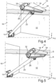
- This decanter 10 is - as can be seen in conjunction with the Fig. 4, 5 and 6 also in respective perspective views - arranged within a clarification tank 12, in particular a mixing reactor of the sewage treatment plant. More precisely, the decanter 10 is fixed by means of a bearing bracket 14 to a basin edge 16 of the clarification tank 12 in a pivotable manner.
- the decanter 10 is essentially T-shaped and comprises an inlet pipe 18, via which clear water can be drawn off from the clarification tank or mixing reactor 12 in a manner described in more detail below and discharged into a drain pipe 20, which is connected to the inlet pipe 18, which in this case tapers in the middle, via respective flange connections 22.
- the clear water can then be fed via the drain pipe 20 to the further process in the biological wastewater treatment. It is to be considered as included in the scope of the invention that several drain pipes 20 can also be provided.
- the inlet pipe 18 is also supported via the drain pipe 20 and pivotally mounted in the area of the bearing bracket 14.
- the decanter 10 can be raised or lowered at an attack point far from the bearing bracket 14, for example by means of a cable winch or similar lifting and lowering device, which is not shown here, as can be seen in conjunction with the Fig. 4, 5 and 6 will be explained in more detail below. Lowering or raising the decanter 10 is therefore carried out by displacement around its pivot axis in the area of the bearing bracket 14.
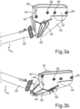
- a displacement device 24 is also provided on the inlet pipe 18, by means of which a cover element 26 in the form of a channel or the like, which will be explained in more detail below, can be displaced between a Fig. 1a , 2a and 3a shown closed position into a respective one, in the Fig. 1b , 2b and 3b shown inflow position, in which the cover element 26 has a plurality of Fig. 6 recognizable inlet openings 28, which pass through the inlet pipe 18 and through which clear water from the clarifier enters the inlet pipe 18 and can then be sucked out via the drain pipe 20.
- the displacement device 24 has respective lever arms 32 mounted on an associated end face 30 of the inlet pipe 18, on which a buoyancy body 34 and a cover element 26 are held.
- these lever arms 32 are designed, for example, as flat plate elements or the like. Other designs would of course also be conceivable.
- the lever arms 32 are mounted on the corresponding end face 36 of the inlet pipe 18 in the area of a bearing point formed by a screw 38, around which the two lever arms 32 can be pivoted relative to the inlet pipe 18 or the respective end face 36.
- Each of the two lever arms 32 also has a respective slotted guide 40 in the form of an arcuate elongated hole, which has the screw 38 as its center, and into which an associated guide element 42 protruding from the end face 36 of the inlet pipe 18 engages.
- the pivoting movement of the two lever arms 32 about the pivot axis formed by the screws 38 is thus limited by the slotted guide 40 and by respective end stops 44, 46.
- the buoyancy element 34 is in the present case designed as a tubular body or hollow body which is adapted to the length of the inlet pipe 18.
- the buoyancy element 34 is in the present case filled with a gas, in particular with air.
- any other buoyancy body made of a different material and in a different shape would also be conceivable.
- Alternatives are familiar to the person skilled in the art.
- the buoyancy element 34 is in the present case firmly connected to the respective lever arm 32 via two respective screws 48.
- the cover element 26 is attached to the underside of the lever arms 32.
- the cover element 26 can be attached to the respective lever arm 32 via a screw 50 and can also be adjusted if necessary. For example, this makes it possible to adjust the position of the cover element 26 relative to the inlet pipe 18 via the screw 50 in order to achieve, for example, sufficient closure of the inlet openings 28 or sufficient tightness between the cover element 26 and the inlet pipe 18 in the closed position of the cover element 26, which will be explained in more detail below.
- Lever arms 32 are arranged on the inlet pipe 18 via a respective adjustable pivot bearing (screw 38), whereby the relative position and tightness of the cover element 26 in its closed position relative to the inlet pipe can be adjusted.
- the cover element 24 and/or the components of the displacement device 24 are preferably made of a steel material, in particular a stainless steel material or a coated steel material, and/or of a plastic or in a hybrid construction of these materials.
- FIG. 4 to 6 in a respective perspective view, the decanter 10 mounted on the edge 16 of the clarification tank 12 or mixing reactor filled with wastewater during lowering into the clarification tank 12 between a parking position and a respective removal position.
- both the inlet pipe 18 and the displacement device 24 with the cover element 26 are still above the floating sludge S, which floats on top of the clear water layer K.
- the displacement device 24 is designed, for example, geometrically and in terms of weight, such that the cover element 26 is in the closed position due to gravity before being immersed in the clarification tank.
- the inlet pipe 18 first dips through the "floating sludge" S and then into the clear water layer K.
- the decanter 10 is then lowered further as the clear water layer sinks.
- the inlet pipe 18, as a result of the displacement in the bearing bracket 14, reaches the immediate area above the sediment layer or the activated sludge that has settled below the clear water layer K in such a way that the cover element 26 is arranged below the inflow openings 28 arranged on the underside of the outlet pipe 18.
- Such an underside arrangement of the cover element 26 relative to the inlet pipe has the particular advantage that the inflow openings 28 provided in the inlet pipe 18 can also be arranged on the underside of the inlet pipe 18.
- This in turn has the advantage that, on the one hand, clear water K can be drawn off close to the sediment layer, but on the other hand, the cover element 26 ensures that no sediment or activated sludge gets into the inlet pipe 18.
- an at least substantially horizontal inflow channel is formed.
- the horizontal inflow channel or the cover element 26 arranged on the underside of the at least one inflow opening 28 ensures that Clear water K can only reach the respective inlet opening 28 in a quasi-horizontal manner, and not vertically, since the respective cover element 26 is located below the inlet opening 28 and overlaps it in its inflow position.
- the clear water K must therefore flow in via the horizontally running inflow channel, which in turn means that no corresponding vortices or similar suction effects below the respective inflow opening 28 can lead to the suction of sediments or activated sludge.
Landscapes
- Chemical & Material Sciences (AREA)
- Chemical Kinetics & Catalysis (AREA)
- Centrifugal Separators (AREA)
Claims (10)
- Décanteur (10) pour station d'épuration, comportant un tuyau d'entrée (18) mobile entre une position de repos et une position de prélèvement, lequel est traversé par au moins une ouverture d'admission (28) par l'intermédiaire de laquelle de l'eau clarifiée peut être soutirée au-dessous d'une couche de boue flottante d'un réservoir de clarification (12) et peut être évacuée dans un tuyau d'évacuation (20), et comportant au moins un élément de couvercle (26) qui, dans une position d'admission, est agencé en dessous et en chevauchement de l'au moins une ouverture d'admission (28) traversant par le bas le tuyau d'entrée (18) et libère celle-ci,
caractérisé en ce que
l'élément de couvercle (26) peut être déplacé entre une position de fermeture fermant l'au moins une ouverture d'admission (28) et la position d'admission au moyen d'un dispositif de déplacement (24) qui comprend au moins un flotteur (34) au moyen duquel l'élément de couvercle (26) peut être déplacé dans la position de fermeture suite à une immersion du flotteur (34) dans les eaux résiduaires, l'élément de couvercle (26) se trouvant dans la position de fermeture avant l'immersion dans le clarificateur (12) et la traversée de la couche de boue flottante et étant déplacé dans la position d'admission par l'impact et l'immersion du flotteur (34) sur ou bien dans la couche d'eau clarifiée (K). - Décanteur (10) selon la revendication 1, caractérisé en ce que
l'au moins un élément de couvercle (26) est agencé au-dessous de l'au moins une ouverture d'admission (28) du tuyau d'entrée (18). - Décanteur (10) selon la revendication 1 ou 2, caractérisé en ce que
l'au moins un élément de couvercle (26), dans la position d'admission, forme un canal d'admission s'étendant au moins sensiblement horizontalement avec une face inférieure du tuyau d'entrée (18) dans sa position de retrait. - Décanteur (10) selon l'une des revendications précédentes, caractérisé en ce que
l'au moins un élément de couvercle (26) ferme au moins sensiblement hermétiquement l'au moins une ouverture d'admission (28) en position fermée. - Décanteur (10) selon l'une des revendications précédentes, caractérisé en ce que
le dispositif de déplacement (24) comprend des bras de levier (32) respectifs montés sur une face frontale du tuyau d'entrée (18), sur lesquels sont agencés d'une part l'au moins un flotteur (34) et d'autre part l'au moins un élément de couvercle (26). - Décanteur (10) selon la revendication 5, caractérisé en ce que
les bras de levier (32) comportent un guide à coulisse (40) respectif pour un élément de guidage (42) associé agencé sur la face frontale (36) du tuyau d'entrée (18). - Décanteur (10) selon l'une des revendications 5 ou 6, caractérisé en ce que
les bras de levier (32) sont agencés sur le tuyau d'entrée (18) par l'intermédiaire d'un palier pivotant respectif réglable et/ou en ce que l'élément de couvercle (26) est réglable et peut être fixé sur le bras de levier (32) respectif, grâce à quoi la position relative et l'étanchéité de l'élément de couvercle (26) dans sa position fermée peuvent être ajustées par rapport au tuyau d'entrée (18). - Décanteur (10) selon l'une des revendications précédentes, caractérisé en ce que
l'au moins un flotteur (34) est conçu comme un corps creux rempli d'un gaz, en particulier d'air. - Décanteur (10) selon l'une des revendications précédentes, caractérisé en ce que
l'élément de couvercle (26) et/ou les composants (32, 34) du dispositif de déplacement (24) sont réalisés en acier, en particulier un acier inoxydable ou un matériau en acier revêtu, et/ou en plastique ou bien en une conception hybride de ces matériaux. - Décanteur selon l'une des revendications précédentes, caractérisé en ce que
le tuyau d'entrée (18) est traversé par une pluralité d'ouvertures d'admission (28) agencées en rangée.
Applications Claiming Priority (3)
| Application Number | Priority Date | Filing Date | Title |
|---|---|---|---|
| DE202020101092.1U DE202020101092U1 (de) | 2020-02-28 | 2020-02-28 | Klarwasser-Abzugseinrichtung (Dekanter) für eine Kläranlage |
| DE102020105262.6A DE102020105262A1 (de) | 2020-02-28 | 2020-02-28 | Klarwasser-Abzugseinrichtung (Dekanter) für eine Kläranlage |
| PCT/EP2021/054720 WO2021170738A1 (fr) | 2020-02-28 | 2021-02-25 | Dispositif de soutirage d'eau clarifiée (décanteur) pour installation de clarification |
Publications (3)
| Publication Number | Publication Date |
|---|---|
| EP4110497A1 EP4110497A1 (fr) | 2023-01-04 |
| EP4110497C0 EP4110497C0 (fr) | 2024-11-27 |
| EP4110497B1 true EP4110497B1 (fr) | 2024-11-27 |
Family
ID=74853616
Family Applications (1)
| Application Number | Title | Priority Date | Filing Date |
|---|---|---|---|
| EP21709354.1A Active EP4110497B1 (fr) | 2020-02-28 | 2021-02-25 | Dispositif de soutirage d'eau clarifiée (décanteur) pour installation de clarification |
Country Status (2)
| Country | Link |
|---|---|
| EP (1) | EP4110497B1 (fr) |
| WO (1) | WO2021170738A1 (fr) |
Citations (3)
| Publication number | Priority date | Publication date | Assignee | Title |
|---|---|---|---|---|
| US4648967A (en) * | 1985-09-20 | 1987-03-10 | Calltharp Glen R | Decanting apparatus |
| DE10311402B4 (de) * | 2002-03-13 | 2004-06-03 | Farmatic Biotech Energy Ag | Dekanter |
| DE102011087966B4 (de) * | 2011-12-08 | 2017-10-05 | Invent Umwelt- Und Verfahrenstechnik Ag | Dekanter |
Family Cites Families (5)
| Publication number | Priority date | Publication date | Assignee | Title |
|---|---|---|---|---|
| US5358644A (en) * | 1993-05-10 | 1994-10-25 | Aqua-Aerobic Systems, Inc. | Method and apparatus for decanting liquid |
| DE19636153A1 (de) * | 1996-09-06 | 1998-03-12 | Schreiber Berthold | Einrichtung zum Abziehen der Klarwasserschicht in einer Kläranlage zur biologischen Abwasserbehandlung |
| AT3001U1 (de) * | 1998-11-05 | 1999-08-25 | Kurt Gassner | Vorrichtung zum abzug von klarwasser aus kläranlagen |
| DE10112339B4 (de) * | 2001-03-13 | 2006-03-23 | Niehüsener, Wilhelm | Vorrichtung zum Abziehen einer vorgegebenen Flüssigkeitsmenge aus einem Flüssigkeitsreservoir mit veränderlichem Flüssigkeitsspiegel |
| DE102006036591B4 (de) * | 2006-08-04 | 2008-08-21 | Invent Umwelt-Und Verfahrenstechnik Ag | Dekanter |
-
2021
- 2021-02-25 EP EP21709354.1A patent/EP4110497B1/fr active Active
- 2021-02-25 WO PCT/EP2021/054720 patent/WO2021170738A1/fr not_active Ceased
Patent Citations (3)
| Publication number | Priority date | Publication date | Assignee | Title |
|---|---|---|---|---|
| US4648967A (en) * | 1985-09-20 | 1987-03-10 | Calltharp Glen R | Decanting apparatus |
| DE10311402B4 (de) * | 2002-03-13 | 2004-06-03 | Farmatic Biotech Energy Ag | Dekanter |
| DE102011087966B4 (de) * | 2011-12-08 | 2017-10-05 | Invent Umwelt- Und Verfahrenstechnik Ag | Dekanter |
Also Published As
| Publication number | Publication date |
|---|---|
| WO2021170738A1 (fr) | 2021-09-02 |
| EP4110497C0 (fr) | 2024-11-27 |
| EP4110497A1 (fr) | 2023-01-04 |
Similar Documents
| Publication | Publication Date | Title |
|---|---|---|
| DE202009010367U1 (de) | Vorrichtung zur Trennung von Regenwasser von chemisch, biologisch und/oder toxisch belasteten Abwässern | |
| EP0037886B1 (fr) | Séparateur de liquides légers | |
| EP1090664A1 (fr) | Evacuation des boues flottantes | |
| EP2100651A1 (fr) | Bassin d'épuration doté d'un dispositif d'évacuation | |
| EP3751067A1 (fr) | Système de dimensionnement de tuyaux | |
| EP0979668B1 (fr) | Décharge pour des eaux clarifiées | |
| DE19636153A1 (de) | Einrichtung zum Abziehen der Klarwasserschicht in einer Kläranlage zur biologischen Abwasserbehandlung | |
| DE202020101092U1 (de) | Klarwasser-Abzugseinrichtung (Dekanter) für eine Kläranlage | |
| DE102009042292B3 (de) | Vorrichtung und Verfahren zum Abzug von Klarwasser aus einem Klärbecken | |
| DE10112339A1 (de) | Vorrichtung zum Abziehen einer vorgegebenen Flüssigkeitsmenge aus einem Flüssigkeitsreservoir mit veränderlichem Flüssigkeitsspiegel | |
| EP4110497A1 (fr) | Dispositif de soutirage d'eau clarifiée (décanteur) pour installation de clarification | |
| DE102020105262A1 (de) | Klarwasser-Abzugseinrichtung (Dekanter) für eine Kläranlage | |
| EP1138363B1 (fr) | Dispositif de soutirage d'eau purifiée d'un récipient lors de la purification biologique d'eaux usées | |
| EP0565483B1 (fr) | Bassin dans une installation d'eaux usées | |
| EP0518912B1 (fr) | Bassin d'epuration ou de sedimentation | |
| DE19580792B4 (de) | Klär- oder Absetzbecken | |
| DE102004057643B4 (de) | Belüftungsvorrichtung zur Belüftung eines Absetzbeckens und Absetzbecken mit einer solchen Belüftungsvorrichtung | |
| DE2740645A1 (de) | Rundraeumer zur abwasserklaerung | |
| DE102016101528A1 (de) | Schwimmstoffabzug | |
| EP3285900B1 (fr) | Procédé servant à évacuer l'eau d'un bassin | |
| EP3392206B1 (fr) | Dispositif d'élévation d'eau doté d'un dispositif de séparation | |
| DE102019122938A1 (de) | Klärüberlauf und Durchlaufbecken | |
| DE202018100026U1 (de) | Rundes Klär- oder Absetzbecken | |
| WO2020083467A1 (fr) | Système filtrant pour purifier de l'eau contaminée par des particules de matières solides et/ou par des polluants dissous | |
| AT409126B (de) | Entnahmevorrichtung zum abziehen der klarphase aus einem sedimentationsbecken |
Legal Events
| Date | Code | Title | Description |
|---|---|---|---|
| STAA | Information on the status of an ep patent application or granted ep patent |
Free format text: STATUS: UNKNOWN |
|
| STAA | Information on the status of an ep patent application or granted ep patent |
Free format text: STATUS: THE INTERNATIONAL PUBLICATION HAS BEEN MADE |
|
| PUAI | Public reference made under article 153(3) epc to a published international application that has entered the european phase |
Free format text: ORIGINAL CODE: 0009012 |
|
| STAA | Information on the status of an ep patent application or granted ep patent |
Free format text: STATUS: REQUEST FOR EXAMINATION WAS MADE |
|
| 17P | Request for examination filed |
Effective date: 20220923 |
|
| AK | Designated contracting states |
Kind code of ref document: A1 Designated state(s): AL AT BE BG CH CY CZ DE DK EE ES FI FR GB GR HR HU IE IS IT LI LT LU LV MC MK MT NL NO PL PT RO RS SE SI SK SM TR |
|
| DAV | Request for validation of the european patent (deleted) | ||
| DAX | Request for extension of the european patent (deleted) | ||
| GRAP | Despatch of communication of intention to grant a patent |
Free format text: ORIGINAL CODE: EPIDOSNIGR1 |
|
| STAA | Information on the status of an ep patent application or granted ep patent |
Free format text: STATUS: GRANT OF PATENT IS INTENDED |
|
| INTG | Intention to grant announced |
Effective date: 20240627 |
|
| GRAS | Grant fee paid |
Free format text: ORIGINAL CODE: EPIDOSNIGR3 |
|
| GRAA | (expected) grant |
Free format text: ORIGINAL CODE: 0009210 |
|
| STAA | Information on the status of an ep patent application or granted ep patent |
Free format text: STATUS: THE PATENT HAS BEEN GRANTED |
|
| AK | Designated contracting states |
Kind code of ref document: B1 Designated state(s): AL AT BE BG CH CY CZ DE DK EE ES FI FR GB GR HR HU IE IS IT LI LT LU LV MC MK MT NL NO PL PT RO RS SE SI SK SM TR |
|
| REG | Reference to a national code |
Ref country code: GB Ref legal event code: FG4D Free format text: NOT ENGLISH |
|
| REG | Reference to a national code |
Ref country code: CH Ref legal event code: EP |
|
| REG | Reference to a national code |
Ref country code: IE Ref legal event code: FG4D Free format text: LANGUAGE OF EP DOCUMENT: GERMAN |
|
| REG | Reference to a national code |
Ref country code: DE Ref legal event code: R096 Ref document number: 502021005940 Country of ref document: DE |
|
| U01 | Request for unitary effect filed |
Effective date: 20241220 |
|
| U07 | Unitary effect registered |
Designated state(s): AT BE BG DE DK EE FI FR IT LT LU LV MT NL PT RO SE SI Effective date: 20250113 |
|
| U20 | Renewal fee for the european patent with unitary effect paid |
Year of fee payment: 5 Effective date: 20250225 |
|
| PG25 | Lapsed in a contracting state [announced via postgrant information from national office to epo] |
Ref country code: IS Free format text: LAPSE BECAUSE OF FAILURE TO SUBMIT A TRANSLATION OF THE DESCRIPTION OR TO PAY THE FEE WITHIN THE PRESCRIBED TIME-LIMIT Effective date: 20250327 Ref country code: HR Free format text: LAPSE BECAUSE OF FAILURE TO SUBMIT A TRANSLATION OF THE DESCRIPTION OR TO PAY THE FEE WITHIN THE PRESCRIBED TIME-LIMIT Effective date: 20241127 |
|
| PG25 | Lapsed in a contracting state [announced via postgrant information from national office to epo] |
Ref country code: ES Free format text: LAPSE BECAUSE OF FAILURE TO SUBMIT A TRANSLATION OF THE DESCRIPTION OR TO PAY THE FEE WITHIN THE PRESCRIBED TIME-LIMIT Effective date: 20241127 |
|
| PG25 | Lapsed in a contracting state [announced via postgrant information from national office to epo] |
Ref country code: NO Free format text: LAPSE BECAUSE OF FAILURE TO SUBMIT A TRANSLATION OF THE DESCRIPTION OR TO PAY THE FEE WITHIN THE PRESCRIBED TIME-LIMIT Effective date: 20250227 |
|
| PG25 | Lapsed in a contracting state [announced via postgrant information from national office to epo] |
Ref country code: GR Free format text: LAPSE BECAUSE OF FAILURE TO SUBMIT A TRANSLATION OF THE DESCRIPTION OR TO PAY THE FEE WITHIN THE PRESCRIBED TIME-LIMIT Effective date: 20250228 |
|
| PG25 | Lapsed in a contracting state [announced via postgrant information from national office to epo] |
Ref country code: PL Free format text: LAPSE BECAUSE OF FAILURE TO SUBMIT A TRANSLATION OF THE DESCRIPTION OR TO PAY THE FEE WITHIN THE PRESCRIBED TIME-LIMIT Effective date: 20241127 |
|
| PG25 | Lapsed in a contracting state [announced via postgrant information from national office to epo] |
Ref country code: RS Free format text: LAPSE BECAUSE OF FAILURE TO SUBMIT A TRANSLATION OF THE DESCRIPTION OR TO PAY THE FEE WITHIN THE PRESCRIBED TIME-LIMIT Effective date: 20250227 |
|
| PG25 | Lapsed in a contracting state [announced via postgrant information from national office to epo] |
Ref country code: SM Free format text: LAPSE BECAUSE OF FAILURE TO SUBMIT A TRANSLATION OF THE DESCRIPTION OR TO PAY THE FEE WITHIN THE PRESCRIBED TIME-LIMIT Effective date: 20241127 |
|
| PG25 | Lapsed in a contracting state [announced via postgrant information from national office to epo] |
Ref country code: SK Free format text: LAPSE BECAUSE OF FAILURE TO SUBMIT A TRANSLATION OF THE DESCRIPTION OR TO PAY THE FEE WITHIN THE PRESCRIBED TIME-LIMIT Effective date: 20241127 |
|
| PG25 | Lapsed in a contracting state [announced via postgrant information from national office to epo] |
Ref country code: CZ Free format text: LAPSE BECAUSE OF FAILURE TO SUBMIT A TRANSLATION OF THE DESCRIPTION OR TO PAY THE FEE WITHIN THE PRESCRIBED TIME-LIMIT Effective date: 20241127 |
|
| PG25 | Lapsed in a contracting state [announced via postgrant information from national office to epo] |
Ref country code: MC Free format text: LAPSE BECAUSE OF FAILURE TO SUBMIT A TRANSLATION OF THE DESCRIPTION OR TO PAY THE FEE WITHIN THE PRESCRIBED TIME-LIMIT Effective date: 20241127 |
|
| REG | Reference to a national code |
Ref country code: CH Ref legal event code: PL |
|
| PLBE | No opposition filed within time limit |
Free format text: ORIGINAL CODE: 0009261 |
|
| STAA | Information on the status of an ep patent application or granted ep patent |
Free format text: STATUS: NO OPPOSITION FILED WITHIN TIME LIMIT |
|
| PG25 | Lapsed in a contracting state [announced via postgrant information from national office to epo] |
Ref country code: CH Free format text: LAPSE BECAUSE OF NON-PAYMENT OF DUE FEES Effective date: 20250228 |
|
| GBPC | Gb: european patent ceased through non-payment of renewal fee |
Effective date: 20250227 |
|
| 26N | No opposition filed |
Effective date: 20250828 |
|
| PG25 | Lapsed in a contracting state [announced via postgrant information from national office to epo] |
Ref country code: GB Free format text: LAPSE BECAUSE OF NON-PAYMENT OF DUE FEES Effective date: 20250227 |
|
| PG25 | Lapsed in a contracting state [announced via postgrant information from national office to epo] |
Ref country code: IE Free format text: LAPSE BECAUSE OF NON-PAYMENT OF DUE FEES Effective date: 20250225 |