EP4110502B1 - Ensemble d'engagement pour engager une plaque filtrante d'un filtre à tambour rotatif, ensemble plateau de filtre et filtre à tambour rotatif - Google Patents
Ensemble d'engagement pour engager une plaque filtrante d'un filtre à tambour rotatif, ensemble plateau de filtre et filtre à tambour rotatif Download PDFInfo
- Publication number
- EP4110502B1 EP4110502B1 EP21713510.2A EP21713510A EP4110502B1 EP 4110502 B1 EP4110502 B1 EP 4110502B1 EP 21713510 A EP21713510 A EP 21713510A EP 4110502 B1 EP4110502 B1 EP 4110502B1
- Authority
- EP
- European Patent Office
- Prior art keywords
- filter
- strip
- clip
- filter plate
- concave area
- Prior art date
- Legal status (The legal status is an assumption and is not a legal conclusion. Google has not performed a legal analysis and makes no representation as to the accuracy of the status listed.)
- Active
Links
Images


Classifications
-
- B—PERFORMING OPERATIONS; TRANSPORTING
- B01—PHYSICAL OR CHEMICAL PROCESSES OR APPARATUS IN GENERAL
- B01D—SEPARATION
- B01D33/00—Filters with filtering elements which move during the filtering operation
- B01D33/06—Filters with filtering elements which move during the filtering operation with rotary cylindrical filtering surfaces, e.g. hollow drums
- B01D33/067—Construction of the filtering drums, e.g. mounting or sealing arrangements
-
- B—PERFORMING OPERATIONS; TRANSPORTING
- B01—PHYSICAL OR CHEMICAL PROCESSES OR APPARATUS IN GENERAL
- B01D—SEPARATION
- B01D33/00—Filters with filtering elements which move during the filtering operation
- B01D33/44—Regenerating the filter material in the filter
-
- B—PERFORMING OPERATIONS; TRANSPORTING
- B01—PHYSICAL OR CHEMICAL PROCESSES OR APPARATUS IN GENERAL
- B01D—SEPARATION
- B01D2201/00—Details relating to filtering apparatus
- B01D2201/40—Special measures for connecting different parts of the filter
- B01D2201/4084—Snap or Seeger ring connecting means
-
- B—PERFORMING OPERATIONS; TRANSPORTING
- B01—PHYSICAL OR CHEMICAL PROCESSES OR APPARATUS IN GENERAL
- B01D—SEPARATION
- B01D2265/00—Casings, housings or mounting for filters specially adapted for separating dispersed particles from gases or vapours
- B01D2265/02—Non-permanent measures for connecting different parts of the filter
- B01D2265/028—Snap, latch or clip connecting means
-
- B—PERFORMING OPERATIONS; TRANSPORTING
- B01—PHYSICAL OR CHEMICAL PROCESSES OR APPARATUS IN GENERAL
- B01D—SEPARATION
- B01D33/00—Filters with filtering elements which move during the filtering operation
- B01D33/06—Filters with filtering elements which move during the filtering operation with rotary cylindrical filtering surfaces, e.g. hollow drums
- B01D33/073—Filters with filtering elements which move during the filtering operation with rotary cylindrical filtering surfaces, e.g. hollow drums arranged for inward flow filtration
Definitions
- a typical rotary drum filter generally comprises a cylindrical drum mounted on a rotational axis for rotation in a tank or vat filled with a slurry.
- the cylindrical drum comprises several divisions (i.e., cylindrical sectors) arrayed around the rotational axis.
- the radially outward surfaces of the divisions define a filter deck assembly.
- operators maintain a pressure differential between the inside and the outside of the drum. That is, the interior of the drum is generally maintained at sub-atmospheric pressure.
- the pressure differential pulls filtrate through the filter deck assembly.
- the residue from the filtrate accumulate on the outer surface of the filter deck assembly.
- This accumulated residue may be referred to as a "pulp mat,” a sediment "cake,” or by other names depending upon the slurry that the rotary drum filter separates.
- the pressure differential continues to pull entrapped liquid from the accumulated residue and thereby begins to dry the accumulated residue.
- the filtrate flows through the filter deck assembly toward the rotational axis.
- the filtrate then flows out of a supportive trunnion into a drop leg.
- the filtrate flowing down through the drop leg creates the vacuum pressure.
- a stationary valve also sits in the trunnion upstream of the drop leg.
- the valve has a first end positioned at approximately the 12 o'clock position (i.e., the apex of rotation when the rotary drum filter is operational) and a second end positioned approximately between the 3 o'clock position (i.e., halfway along the downward rotational journey) and the 5 o'clock position (i.e., several degrees before the nadir of rotation).
- the valve blocks the portion of the division that exits into the trunnion, thereby releasing vacuum pressure along the arc of the valve.
- a doctor blade, roller, belt, or other apparatus removes the accumulated residue from the filter deck assembly on the now pressure-equalized division. Typically, additional equipment then collects this residue for further processing.
- the now cleaned filter deck assembly continues to rotate downwardly toward the slurry. As the division rotates past the end of the valve, the valve no longer blocks the portion of the division that exits into the trunnion and the sub-atmospheric pressure is again applied, thereby permitting the process to repeat as the division rotates through the slurry.
- Traditional filter deck assemblies comprise corrugated filter plates. Each filter plate spans one or more grid supports. The respective filter plate ends engage a top hat-shaped mounting clip mounted on a grid support. Installers and servicers weld at least one end of the filter plate to a mounting clip to prevent filtrate from leaking back into the vat when the filter plate rotates downwardly.
- the "top hat" mounting clips also have a cap strip welded on top of (i.e., radially outward of) each mounting clip to define a generally C-shaped recess. Each end of the filter plate rests in one of these C-shaped recesses.
- Installers and servicers spot weld or tungsten inert gas (“TIG”) weld these cap strips to the mounting clips. Installers and servicers may also weld the ends of the filter plate to the mounting clip and/or cap strip to form a secure seal and fixedly install the filter plates.
- TOG tungsten inert gas
- the filter plates, mounting clips, and cap strips, are typically all manufactured from stainless steel.
- the temperature profile of the cylindrical drum may vary significantly, at least at startup.
- the starting temperature of the pulp slurry may be in a range of 82 degrees Celsius (°C) (180 degrees Fahrenheit (°F)) to 93 °C (200 °F) in a first stage vat.
- the filtered pulp generally cools to about 60 °C (about 140 °F) by the time it is removed from the drum.
- the drum divisions that start in the vat will typically have a higher average temperature than the divisions that start above the vat.
- washers may spray the mat with water or other fluid to displace the entrapped slurry liquid.
- the expansion and contraction of the stainless steel in response to temperature fluctuations can stress the filter deck assembly welds, particularly the welds engaging the filter plates, mounting clips, and cap strips. Even though rotation and the materials of the cylindrical drum may eventually reduce the temperature differential over time, any remaining temperature differential will still stress the welds. If left unaddressed, excessive or prolonged periods of stress will lead to weld failure, which will reduce the efficiency of the rotary drum filter by allowing filtrate to flow back out of the filter deck assembly and into the vat.
- Giasson a document that discloses features falling under the preamble of claim 1.
- This design requires welding, gluing, or otherwise affixing the "top hat” mounting clips to the support grids and having a “snap in” cap strip.
- the "snap in” cap strip comprises a U-shaped piece and a generally planar top piece (i.e., a traditional cap strip) that is welded, glued, or otherwise fixedly engaged to the U-shaped piece.
- Giasson recommends welding or otherwise permanently engaging the removable cap strip into place.
- the present invention provides an engagement assembly as recited in claim 1.
- the present disclosure relates generally to rotary drum filters configured to filter slurries, and more particularly to filter plates in rotary vacuum drum washers, thickeners, and filters used in the pulp and paper, chemical recovery, waste separation, and mining industries.
- the problem of production loss due to weld fatigue in welds between filter plates and mounting clips in a filter plate assembly of a rotary drum filter can be mitigated by aspects of the present disclosure.
- an engagement assembly for a rotary drum filter.
- the engagement assembly may include: a retaining clip having a body, a first shelf extending outwardly from the body in a first direction and a second shelf extending outwardly from the body in a direction opposite the first direction; and an S-clip having a major concave area configured to receive a leading end or a trailing end of a filter plate, and a minor concave area configured to receive the first shelf or the second shelf of the retaining clip.
- the filter deck assembly may include: a filter plate having a leading end distally disposed from a trailing end; and an engagement assembly configured to engage the filter plate.
- the engagement assembly may include a retaining clip having a body, a first shelf extending outwardly from the body in a first direction and a second shelf extending outwardly from the body in a direction opposite the first direction.
- the engagement assembly may include an S-clip having a major concave area configured to receive the leading end or the trailing end of the filter plate, and a minor concave area configured to receive the first shelf or the second shelf of the retaining clip.
- the rotary drum filter may include a filter deck assembly, and grid supports configured to support the filter deck assembly.
- the filter deck assembly may include a filter plate having a leading end distally disposed from a trailing end, and an engagement assembly configured to engage the filter plate.
- the engagement assembly may include a retaining clip having a body, a first shelf extending outwardly from the body in a first direction and a second shelf extending outwardly from the body in a direction opposite the first direction, and an S-clip having a major concave area configured to receive the leading end or the trailing end of the filter plate, and a minor concave area configured to receive the first shelf or the second shelf of the retaining clip.
- references in the specification to "one embodiment,” “an embodiment,” “an exemplary embodiment,” etc., indicate that the embodiment described may include a particular feature, structure, or characteristic, but every embodiment may not necessarily include the particular feature, structure, or characteristic. Moreover, such phrases are not necessarily referring to the same embodiment. Further, when a particular feature, structure, or characteristic is described in connection with an embodiment, it is submitted that it is within the knowledge of one skilled in the art to affect such feature, structure, or characteristic in connection with other embodiments whether or not explicitly described.
- the terms “upper” and “lower” are relative to each other in location, i.e., an upper component is located at a higher elevation than a lower component in a given orientation, but these terms can change if the device is flipped.
- the terms “inlet' and “outlet” are relative to a fluid flowing through them with respect to a given structure, e.g., a fluid flows through the inlet into the structure and flows through the outlet out of the structure.
- upstream and “downstream” are relative to the direction in which a fluid flows through various components, i.e., the flow of fluids through an upstream component prior to flowing through the downstream component.
- top and bottom are used to refer to locations/surfaces where the top is always higher than the bottom/base relative to an absolute reference, e.g., the surface of the earth.
- upwards and “downwards” are also relative to an absolute reference; an upwards flow is always against the gravity of the earth.
- Fig. 1 is a perspective view of a rotary drum filter 10.
- the rotary drum filter 10 may be, for example, a vacuum washer used in the pulp and paper industry.
- a typical rotary drum filter 10 includes a cylindrical drum 12 disposed in a vat (not shown).
- Closure plates 14 bound each end 7, 9 of the drum 12.
- Support ribs 21 extend generally radially outward from structures surrounding the axis of rotation toward the outer circumference of the drum 12.
- Multiple ring supports 19 support the filter deck assembly 20.
- a trunnion 16 extends from each end 7, 9 of the drum 12 and rotatably mounts the drum 12 to adjacent bearing and pedestal assemblies 18.
- One of the trunnions 16a is hollow and connects to a drop leg (not shown).
- the drop leg pulls air through the drum and thereby draws filtrate 11 through the rotary drum filter 10 under vacuum.
- a number of filtrate conduits 22 disposed between the hollow trunnion 16a and the filtrate chambers 24 allow filtrate 11 to fluidly communicate with the drop leg.
- a screen 8 typically a wire mesh (also referred to as a "face wire”), cloth, synthetic textile, or plastic screen encircles the drum 12.
- the vat is filled with a slurry.
- the drum 12 rotates in rotational direction R, which in this example is counter-clockwise.
- the vacuum pressure facilitates the accumulation of residue 6 on the screen 8.
- filtrate 11 percolates through the filter deck assembly 20 and eventually flows through the filtrate conduits 22 into the drop leg.
- the residue 6 begins to dry and a doctor blade, belt, roller, or other device (not shown) eventually scrapes the residue 6 from the screen 8 before that section of the screen 8 rotates back into the slurry to repeat the process.
- the slurry is a typically a mixture of pulp and water called a "pulp stock.”
- the residue 6 on the screen are typically known as a "pulp mat.”
- the rotary drum filter may be known as a thickener.
- the residue 6 is typically cakes of mineral sediment.
- lime mud filters are typically used to recover lime from spent pulp and paper liquors.
- the filtrate 11 typically comprises water and the residue 6 comprises lime mud.
- FIG. 2 is a detailed perspective view of a portion of the filter deck assembly 20 of FIG. 1 .
- the screen 8 rests atop an array of filter plates 4.
- the filter plates 4 are typically corrugated filter plates 4a having a plurality of ridges 3 and channels 5. Corrugated filter plates 4a are generally preferred because the corrugations increase the surface area available for holding excess filtrate 11 and thereby permit the rotary drum filter 10 to rotate at higher speeds than would typically be achievable in a rotary drum filter 10 having a comparatively flat filter plate (i.e., a filter plate that curves slightly to match the arc of the drum, but that is otherwise flat). Furthermore, the corrugations easily expand or contract slightly to accommodate thermal expansion.
- Each filter plate 4 has a width W and a length L.
- the filter plate 4 has areas defining multiple drainage slots 17 disposed throughout the filter plate 4.
- the multiple drainage slots 17 are disposed in the channels 5.
- the drainage slots 17 may be louvered to collect pools of filtrate 11 on the downturn.
- the filter plate 4 spans one or more grid supports 30. Adjacent grid supports 30 and the filter plate 4 define one or more filtrate chambers 24. In operation, filtrate 11 flows through the screen 8 and through the drainage slots 17 on the upturn and part of the downturn. The filtrate 11 then flows through the filtrate chambers 24 before flowing further to the filtrate conduits 22 and drop leg.
- the filter plate 4 further comprises a leading end 32 and a trailing end 34.
- the leading end 32 is the end that first exits the slurry when the particular section of the filter plate 4 is moving upward toward the apex of rotation and the leading end 32 is likewise the first end to fall back under the level of the slurry when the section of the filter plate 4 is moving downward toward the nadir of rotation.
- the trailing end 34 is distally disposed from the leading end 32.
- the trailing end 34 is the second end to exit the slurry when the filter plate 4 is moving toward the apex of rotation.
- the respective ends 32, 34 of the filter plates 4 engage a "top hat"-shaped mounting clip 25 mounted on a grid support 30.
- installers and servicers have welded or otherwise rigidly affixed at least one end 32 or 34 of the filter plate 4 to a mounting clip 25 to prevent filtrate 11 from leaking back out of the filter plate 4 when the filter plate 4 is on the downturn.
- the top hat mounting clips 25 also have a cap strip 27 welded or otherwise rigidly affixed to each mounting clip 25. In practice, installers and services spot weld or TIG weld these cap strips 27 to the mounting clips 25.
- the recess 23 i.e., the generally C-shaped feature
- the recess 23 i.e., the generally C-shaped feature
- the rigidly affixed cap strips 27 create ongoing maintenance problems.
- the rigidly affixed cap strip 27 prevent a servicer from easily accessing and removing or replacing the filter plate 4. Additionally, if the cap strips 27 have been welded to the mounting clips 25, the environment within the rotary drum filter 10 can lead to weld fatigue and corrosion. In extreme cases, broken welds create loose cap strips 27 and filter plates 4, which can damage the doctor blades, rollers, belts, or other device configured to remove the residue 6 from the screen 8.
- the loose cap strips 27 or filter plates 4 can likewise tear or otherwise damage the screen 8. This permits filtrate 11 to flow both between drum divisions and back out of filter plate 4 and screen 8, thereby reducing the overall efficiency of the system.
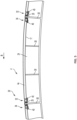
- FIG. 3 is a perspective view of an exemplary filter plate and an exemplary engagement assembly comprising an S-clip at both the leading end and the trailing end of the filter plate according to some aspects of the present disclosure.
- the filter deck assembly 20 may include a filter plate 4 having a leading end 32 distally disposed from a trailing end 34, an engagement assembly 35 configured to engage the filter plate.
- the engagement assembly 35 may include an "S" shaped clip 45 (also referred to herein as an S-clip), and a retaining clip 40.
- FIG. 4 is a detailed view of the exemplary engagement assembly 35 shown in FIG. 3 according to some aspects of the present disclosure.
- the retaining clip 40 may include a body 28, a first shelf 71, and a second shelf 73. Both the first shelf 71 and the second shelf 73 may extend outwardly from the body 28.
- a major concave area "M" of the S-clip 45 may be configured to receive the leading end 32 or the trailing end 34 of the filter plate 4.
- a minor concave area "m" of the S-clip 45 may be configured to receive the first shelf 71 or the second shelf 73 of the retaining clip 40.
- the exemplary S-clip 45 defines the major concave area M adjacently disposed to the minor concave area m.
- the minor concave area m may be separated from the major concave area M by a horizontal body strip 61 of the S-clip 45.
- the minor concave area m may be disposed in a direction that is opposite of a direction of the major concave area M. That is, the opening of the minor concave area m may face the opposite direction from the opening of the major concave area M.
- the S-clip 45 may include a first horizontal strip 51 configured to engage a first vertical strip 53 at a first end 52 of the first vertical strip 53.
- a second end 54 of the first vertical strip 53 may be configured to engage a first end 56 of a horizontal body strip 61.
- the first end 52 of the first vertical strip 53 may be distally disposed from the second end 54 of the first vertical strip 53.
- the first horizontal strip 51, the first vertical strip 53, and the first horizontal body strip 61 may define the major concave area M.
- the S-clip 45 may further include a second horizontal strip 57 configured to engage a second vertical strip 55 at a first end 58 of the second vertical strip 55.
- a second end 59 of the second vertical strip 55 may be configured to engage a second end 60 of the horizontal body strip 61, wherein the second end 60 of the horizontal body strip 61 may be distally disposed from the first end 56 of the horizontal body strip 61.
- the second end 59 of the second vertical strip 55 may be distally disposed from the first end 58 of the second vertical strip.
- the second horizontal strip 57, the second vertical strip 55, and the horizontal body strip 61 may define the minor concave area m.
- the leading end 32 of the filter plate 4 or the trailing end 34 of the filter plate 4 may be inserted into the major concave area M of the S-clip 45, and the major concave area M of the S-clip 45 may be configured to receive the leading end 32 of the filter plate 4 or the trailing end 34 of the filter plate 4.
- the leading end 32 and the trailing end 34 of the filter plate 4 may be tapered such that the leading end 32 is retained within the major concave area M of the S-clip 45 while being supported by a horizontal body strip 61 of the S-clip 45.
- the minor concave area m of the S-clip 45 that supports the trailing end 34 of the filter plate 4 may engage the first shelf 71 of the retaining clip 40 such that the horizontal body strip 61 of the S-clip 45 and the second horizontal strip 57 of the S-clip 45 contact the first shelf 71 of the retaining clip 40.
- the minor concave area m of the S-clip 45 that supports the leading end 32 of the filter plate 4 may engage the second shelf 73 of the retaining clip 40 such that the horizontal body strip 61 of the S-clip 45 and the second horizontal strip 57 of the S-clip 45 contact the second shelf 73 of the retaining clip 40.
- leading end 32 filter plate 4 or the trailing end 34 of the filter plate 4 may be slid into the major concave area M of the S-clip 45.
- leading end 32 or the trailing end 34 of the filter plate 4 may be angled into the major concave area M of the S-clip 45 laterally.
- the height of the major concave area M may be greater than the height of the leading end 32 of the filter plate 4 and the trailing end 34 of the filter plate 4 so as to secure the leading end 32 of the filter plate 4 and the trailing end 34 of the filter plate 4 into the major concave area M of the S-clip 45 when the filter plate 4 is installed in the filter deck assembly 20.
- the major concave area M may surround the top, lateral end, and bottom portions of the leading end 32 of the filter plate 4 and/or the trailing end 34 of the filter plate 4, and may prevent edges of the leading end 32 and/or the trailing end 34 from contacting the screen 8 thereby preventing such edges from piecing holes in the screen 8. Holes in the screen 8 contribute to production loss.
- the deepest portion of the minor concave area m may extend beyond the end of the horizontal strip 51 defining the major concave area M, and the deepest portion of the major concave area M may extend beyond the second horizontal strip 57 defining minor concave area m.
- the "top hat" mounting clip 25 is welded to a grid support 30.
- the S-clip 45 of the present disclosure slides onto one of the shelves (e.g., the first shelf 71 or the second shelf 73) of the retaining clip 40 without the use of welds or other fastener.
- Another advantage of the present disclosure is that there is no longer a need for cap strips, thereby reducing the overall welds in the filter deck assembly and potentially extending the useful life of the assembly.
- the minor concave area m of the S-clip 45 is configured to receive first shelf 71 or the second shelf 73 of the retaining clip 40.
- first shelf 71 or the second shelf 73 of the retaining clip 40 may be pushed into the minor concave area m of the S-clip 45 laterally.
- the minor concave area m of the S-clip 45 is also configured to receive the first shelf 71 or the second shelf 73 of the retaining clip 40.
- the height of the minor concave area m may be greater than the height of the first shelf 71 or the second shelf 73 of the retaining clip 40 so as to secure the first shelf 71 or the second shelf 73 of the retaining clip 40 into the minor concave area m when the S-clip 45 is installed in the filter deck assembly 20.
- the S-clip 45 may be constructed from stainless steel or a polymer configured to be resistant to heat up to 93 °C (200 °F).
- Other shapes for the clip that fix the retaining clip 40 to the filter plate 4 without the use of a top hat clip (e.g., the top hat mounting clip 25) and without exposing the ends 32, 34 of the filter plate 4 to the screen 8 may be used without departing from the scope of the present disclosure.
- An optional seal can be made from a gasket material to prevent leaking around the ends 32, 34 of the filter plate 4.
- the seal may have a rectangular shape and may be disposed between a surface of the major concave area M and the leading end 32 of the filter plate 4.
- a shaped seal or an adhesive material such as RTV silicone may be applied between the bottom of the leading end 32 of the filter plate 4 and the horizontal body strip 61 of the S-clip 45 to create the seal.
- the seal strip may positioned on the leading end of the filter plate to minimize filtrate leakage from under the filter plate and rewetting the pulp mat once the vacuum to the filter plate is cut off.
- first horizontal strip 51 “first vertical strip 53,” “first end 52 of the first vertical strip 53,” “second end 54 of the first vertical strip 53,” “horizontal body strip 61,” “first end 56 of the horizontal body strip 61,” “second end 60 of the horizontal body strip 61,” “second vertical strip 55,” “first end 58 of the second vertical strip 55,” “second end 59 of the second vertical strip 55,” and “a second horizontal strip 57” are used to refer to parts of the S-clip 45 regardless of how the S-clip 45 is manufactured.
- an exemplary S-clip 45 can be fabricated from multiple strips of material.
- an exemplary S-clip 45 can be manufactured by bending a plate of material to adopt the "S" shaped form as described in this disclosure.
- a second vertical strip 55 may be created by bending a plate of material back over itself.
- the second vertical strip 55 is the section of plate connecting the substantially parallel horizontal body strip 61 and second horizontal strip 57.
- FIG. 5 is a cross-sectional side view of an exemplary filter deck assembly 20 including the exemplary engagement assembly 35 according to some aspects of the present disclosure.
- two S-clips 45a, 45b may be disposed on each retaining clip 40.
- a first S-clip 45a engages the first shelf 71 of the retaining clip 40 and a trailing end 34 of an adjacent filter plate 4.
- a second S-clip 45b engages the second shelf 73 of the retaining clip 40 and engages a leading end 32 of a second adjacent filter plate 4'.
- the filter plates 4 and 4' may be corrugated filter plates 4a.
Landscapes
- Chemical & Material Sciences (AREA)
- Chemical Kinetics & Catalysis (AREA)
- Filtration Of Liquid (AREA)
- Snaps, Bayonet Connections, Set Pins, And Snap Rings (AREA)
- Filtering Of Dispersed Particles In Gases (AREA)
- Paper (AREA)
Claims (8)
- Ensemble (35) de mise en prise pour la mise en prise d'une plaque (4) filtrante qui s'étend sur au moins un support (30) de grille d'un filtre (10) à tambour rotatif, l'ensemble (35) de mise en prise comprenant :une pince (40) de retenue configurée pour être montée sur le support (30) de grille, la pince (40) de retenue ayant un corps (28), un premier plateau (71) s'étendant vers l'extérieur à partir du corps (28) dans une première direction et un deuxième plateau (73) s'étendant vers l'extérieur à partir du corps (28) dans une direction opposée à la première direction ;caractérisé en ce que
l'ensemble (35) de mise en prise comprend en outre une pince (45) en S pour la fixation de la pince (40) de retenue sur la plaque (4) filtrante, la pince (45) en S ayant une zone (M) concave majeure configurée pour recevoir une extrémité (32) d'attaque ou une extrémité (34) de fuite d'une plaque (4) filtrante, et une zone (m) concave mineure configurée pour recevoir le premier plateau (71) ou le deuxième plateau (73) de la pince (40) de retenue, dans lequel :la zone (M) concave majeure est disposée de manière adjacente à la zone (m) concave mineure,la zone (m) concave mineure est séparée de la zone concave majeure par une bande (61) de corps de la pince (45) en S, etdans lequel la zone (m) concave mineure est disposée dans une direction qui est à l'opposé d'une direction de la zone (M) concave majeure. - Ensemble (35) de mise en prise selon la revendication 1, dans lequel la pince (45) en S comprend en outre :une première bande (51) horizontale configurée pour se mettre en prise avec une première bande (53) verticale à une première extrémité (52) de la première bande (53) verticale ; etune bande (61) de corps horizontale ayant une première extrémité (56) configurée pour se mettre en prise avec la première bande (53) verticale à une deuxième extrémité (54) de la première bande (53) verticale,dans lequel la première extrémité (52) de la première bande (53) verticale est disposée de manière distale par rapport à la deuxième extrémité (54) de la première bande (53) verticale, etdans lequel la première bande (51) horizontale, la première bande (53) verticale et la bande (61) de corps horizontale définissent la zone (M) concave majeure.
- Ensemble (35) de mise en prise selon la revendication 2, dans lequel la pince (45) en S comprend en outre :une deuxième bande (55) verticale ayant une première extrémité (58) et une deuxième extrémité (59), dans lequel la deuxième extrémité (59) de la deuxième bande (55) verticale est configurée pour se mettre en prise avec une deuxième extrémité (60) de la bande (61) de corps horizontale ; etune deuxième bande (57) horizontale configurée pour se mettre en prise avec la première extrémité (58) de la deuxième bande (55) verticale,dans lequel la deuxième extrémité (60) de la bande (61) de corps horizontale est disposée de manière distale par rapport à la première extrémité (56) de la bande (60) de corps horizontale,dans lequel la deuxième extrémité (59) de la deuxième bande (55) verticale est disposée de manière distale par rapport à la première extrémité (58) de la deuxième bande (55) verticale, etdans lequel la deuxième bande (57) horizontale, la deuxième bande (55) verticale et la bande (61) de corps horizontale définissent la zone (m) concave mineure.
- Ensemble (35) de mise en prise selon la revendication 1, dans lequel la zone (M) concave majeure encercle une extrémité (32) d'attaque de la plaque (4) filtrante ou une extrémité (34) de fuite de la plaque (4) filtrante.
- Ensemble (35) de mise en prise selon la revendication 1, dans lequel une hauteur de la zone (M) concave majeure est supérieure à une hauteur de l'extrémité (32) d'attaque de la plaque (4) filtrante et de l'extrémité (34) de fuite de la plaque (4) filtrante.
- Ensemble (35) de mise en prise selon la revendication 1, dans lequel la pince (45) en S comprend de l'acier inoxydable ou un polymère configuré pour être résistant à la chaleur jusqu'à 93 degrés Celsius (200 degrés Fahrenheit).
- Ensemble (20) plateforme filtrante pour un filtre (10) à tambour rotatif, l'ensemble (20) plateforme filtrante comprenant :une plaque (4) filtrante ayant une extrémité d'attaque disposée de manière distale par rapport à une extrémité de fuite ; etun ensemble (35) de mise en prise selon l'une quelconque des revendications 1 à 6, configuré pour se mettre en prise avec la plaque (4) filtrante.
- Filtre (10) à tambour rotatif, comprenant :un ensemble (20) plateforme filtrante selon la revendication 7 ; etdes supports (30) de grille configurés pour porter l'ensemble (20) plateforme filtrante.
Applications Claiming Priority (2)
| Application Number | Priority Date | Filing Date | Title |
|---|---|---|---|
| US202062982837P | 2020-02-28 | 2020-02-28 | |
| PCT/US2021/019836 WO2021173945A1 (fr) | 2020-02-28 | 2021-02-26 | Ensemble plateau de filtre à tambour rotatif comprenant une pince |
Publications (2)
| Publication Number | Publication Date |
|---|---|
| EP4110502A1 EP4110502A1 (fr) | 2023-01-04 |
| EP4110502B1 true EP4110502B1 (fr) | 2024-09-11 |
Family
ID=75111884
Family Applications (1)
| Application Number | Title | Priority Date | Filing Date |
|---|---|---|---|
| EP21713510.2A Active EP4110502B1 (fr) | 2020-02-28 | 2021-02-26 | Ensemble d'engagement pour engager une plaque filtrante d'un filtre à tambour rotatif, ensemble plateau de filtre et filtre à tambour rotatif |
Country Status (6)
| Country | Link |
|---|---|
| US (1) | US20210268410A1 (fr) |
| EP (1) | EP4110502B1 (fr) |
| CA (1) | CA3166149C (fr) |
| CL (1) | CL2022002314A1 (fr) |
| FI (1) | FI4110502T3 (fr) |
| WO (1) | WO2021173945A1 (fr) |
Families Citing this family (7)
| Publication number | Priority date | Publication date | Assignee | Title |
|---|---|---|---|---|
| WO2018225014A1 (fr) * | 2017-06-07 | 2018-12-13 | Sabic Global Technologies B.V. | Filtre à vide rotatif, procédé et utilisation |
| US12551825B2 (en) * | 2018-06-20 | 2026-02-17 | Andritz Inc. | Drum washer with gravity assist drainage |
| SE542326C2 (en) * | 2018-06-21 | 2020-04-14 | Valmet Oy | Vacuum filter |
| DE102018007294A1 (de) * | 2018-09-14 | 2020-03-19 | Guntram Krettek | Verfahren zum Fixieren eines Bleches und damit hergestellte Filtereinrichtung |
| US11890563B2 (en) * | 2019-02-01 | 2024-02-06 | Walk Industrial, Inc. | Grid cover for filter system |
| US20220355225A1 (en) * | 2021-05-10 | 2022-11-10 | Lyco Manufacturing Inc. | Externally Fed Screen for Filtration |
| SE547820C2 (en) * | 2023-12-07 | 2025-12-02 | Valmet Oy | Corrugated cover assembly for a vacuum rotary filter drum |
Family Cites Families (58)
| Publication number | Priority date | Publication date | Assignee | Title |
|---|---|---|---|---|
| US2161997A (en) * | 1939-06-13 | Stovepipe | ||
| US1667465A (en) * | 1925-03-10 | 1928-04-24 | Justin F Wait | Filter and filtering method |
| BE531925A (fr) * | 1939-03-06 | |||
| US2381635A (en) * | 1942-06-15 | 1945-08-07 | United States Gypsum Co | Partition structure |
| US2491700A (en) * | 1945-11-10 | 1949-12-20 | Zwerling Harry | Braced conduit construction |
| US2472558A (en) * | 1945-12-27 | 1949-06-07 | Oliver United Filters Inc | Rotary drum filter |
| US2534161A (en) * | 1948-11-06 | 1950-12-12 | Lummus Co | Filter drum screen fastening means |
| US2593064A (en) * | 1949-03-19 | 1952-04-15 | Jacob A C Silberman | Fastener |
| US2724507A (en) * | 1953-05-06 | 1955-11-22 | Filtration Engineers Inc | Filter division strip |
| US3175691A (en) * | 1956-08-31 | 1965-03-30 | Dorr Oliver Inc | Device for detachably securing drainage members on filters |
| US3027011A (en) * | 1958-01-06 | 1962-03-27 | Whiting Corp | Pulp washer and filter |
| US3033373A (en) * | 1958-07-24 | 1962-05-08 | Mueller Hans | Filter cloth fastening means |
| US3225935A (en) * | 1963-01-10 | 1965-12-28 | Us Rubber Co | Drainage bed |
| GB1032544A (en) * | 1963-11-19 | 1966-06-08 | Ft Products Ltd | An improved fastener |
| FR1397354A (fr) * | 1964-03-16 | 1965-04-30 | Nord Aviation | Dispositif de jonction de panneaux amovibles |
| US3353675A (en) * | 1965-10-21 | 1967-11-21 | Mero & Company Inc | Drum filter element attaching means |
| US3371900A (en) * | 1966-02-14 | 1968-03-05 | Prudential Lighting Corp | Unitary double-detent connector for lighting fixtures |
| GB1269114A (en) * | 1969-06-23 | 1972-04-06 | Ft Products Ltd | An improved fastener |
| US3760547A (en) * | 1969-08-13 | 1973-09-25 | J Brenneman | Spline and seat connector assemblies |
| US3627362A (en) * | 1969-08-13 | 1971-12-14 | John H Brenneman | Spline and seat connector assemblies |
| US3837499A (en) * | 1971-03-29 | 1974-09-24 | Improved Machinery Inc | Drum structure for rotary drum filtering apparatus |
| US3954622A (en) * | 1973-05-29 | 1976-05-04 | Dorr-Oliver Incorporated | Sealing means for divider strips on filter drums |
| US4133161A (en) * | 1975-05-01 | 1979-01-09 | Lester Allan G | Panel assemblies and methods of forming same |
| FR2413891A1 (fr) * | 1978-01-06 | 1979-08-03 | Beghin Say Sa | Attaches pliees et procede de fabrication |
| US4157301A (en) * | 1978-03-15 | 1979-06-05 | Envirotech Corporation | Drum construction for rotary drum filter |
| DE2853254C2 (de) * | 1978-12-09 | 1982-12-09 | Fa. A. Raymond, 7850 Lörrach | Zierleistenklammer |
| US4308143A (en) * | 1979-10-29 | 1981-12-29 | Ethyl Corporation | Rotary drum filter |
| US4276169A (en) * | 1980-04-10 | 1981-06-30 | Dorr-Oliver Incorporated | Drainage deck assembly for rotary vacuum drum filter |
| US4309288A (en) * | 1980-08-07 | 1982-01-05 | Exxon Research & Engineering Co. | Rotary drum filter |
| US4330405A (en) * | 1980-09-29 | 1982-05-18 | Davis Kent L | Vacuum disc filter |
| US4408939A (en) * | 1981-03-05 | 1983-10-11 | Pathfinder Auto Lamp Company | Composite fastener for attaching splash guard |
| WO1990000091A1 (fr) * | 1987-02-05 | 1990-01-11 | Nylok Fastener Corporation | Appareil et procede pour realiser des ecrous-coulisseaux de blocage |
| US4826375A (en) * | 1987-08-17 | 1989-05-02 | Eaton Corporation | Variable diameter screw fastener |
| FR2621961B1 (fr) * | 1987-10-20 | 1990-02-02 | Peugeot | Agrafe de fixation d'un tapis sur un plancher |
| US4957630A (en) * | 1988-12-27 | 1990-09-18 | Bratten Jack R | Drum filter with divergent hole perforated filter media |
| SE464967B (sv) * | 1990-10-23 | 1991-07-08 | Tamfelt Oy Ab | Filterpaase foer maskinsikt |
| US5451075A (en) * | 1994-06-29 | 1995-09-19 | Davidson Textron Inc. | Closure for an air bag assembly |
| AT401355B (de) * | 1994-09-08 | 1996-08-26 | Andritz Patentverwaltung | Scheibenfilter zum abtrennen von flüssigkeiten aus einer suspension, insbesondere faserstoffsuspension |
| JPH08226420A (ja) * | 1995-02-20 | 1996-09-03 | Nifco Inc | 板体の連結具 |
| US5791719A (en) * | 1996-05-07 | 1998-08-11 | Plastic Form, Inc. | Vehicle deflector mounting system |
| US5832871A (en) * | 1997-05-05 | 1998-11-10 | All-Glass Aquarium Co., Inc. | Vivarium with simplified cover cover retention |
| WO2001038745A2 (fr) * | 1999-11-29 | 2001-05-31 | Southco, Inc. | Dispositif de fixation a capacite de cisaillement |
| US6363676B1 (en) * | 2000-02-03 | 2002-04-02 | Jancor, Inc. | Siding having double thick nail hem |
| US6941707B2 (en) * | 2003-05-02 | 2005-09-13 | Certainteed Corporation | Vented soffit panel |
| JP4472325B2 (ja) * | 2003-12-25 | 2010-06-02 | 三和パッキング工業株式会社 | 緩衝装置 |
| US7698867B1 (en) * | 2007-06-13 | 2010-04-20 | Stucko Craig B | Siding trim clip with triangular gripping pattern |
| US8252181B2 (en) * | 2007-07-19 | 2012-08-28 | Gerald Pitre | Horizontal ore filter with replaceable filter elements |
| US8256165B2 (en) * | 2009-06-02 | 2012-09-04 | Crego Metal Systems, Inc. | Single ply roofing system |
| JP4901992B1 (ja) * | 2010-12-22 | 2012-03-21 | 三和パッキング工業株式会社 | 緩衝装置及び金属製カバー |
| US9133869B2 (en) * | 2011-08-01 | 2015-09-15 | Elringklinger Ag | Shielding device with a shielding element and at least one temperature and oscillation-decoupled fastening device |
| DE202011108752U1 (de) * | 2011-12-06 | 2012-01-24 | Akzenta Paneele + Profile Gmbh | Verriegelungssystem für Paneelen und Paneel mit Verriegelungssystem |
| MX394544B (es) * | 2014-06-04 | 2025-03-24 | Sti Holdings Inc | Tratamientos y articulaciones para borde del panel compuesto y cuerpo de carga que tiene los mismos. |
| US9669337B2 (en) | 2015-03-11 | 2017-06-06 | GL&V Luxembourg Sàrl | Method of constructing a rotary drum filtering apparatus |
| US9964175B2 (en) * | 2015-04-24 | 2018-05-08 | Federal-Mogul Llc | Heat and vibration mounting isolator for a heat shield, heat shield assembly and method of construction thereof |
| JP6087482B1 (ja) * | 2015-10-09 | 2017-03-01 | ニチアス株式会社 | 連結具 |
| US10359212B2 (en) * | 2016-05-11 | 2019-07-23 | Nation Wide Products Llc | Apparatus and method for securing an air conditioning unit in a window |
| US9915063B1 (en) * | 2016-08-26 | 2018-03-13 | Petersen Aluminum Corporation | Wall panel clip and high wind resistant wall panel systems |
| WO2018225014A1 (fr) * | 2017-06-07 | 2018-12-13 | Sabic Global Technologies B.V. | Filtre à vide rotatif, procédé et utilisation |
-
2021
- 2021-02-26 EP EP21713510.2A patent/EP4110502B1/fr active Active
- 2021-02-26 WO PCT/US2021/019836 patent/WO2021173945A1/fr not_active Ceased
- 2021-02-26 US US17/186,507 patent/US20210268410A1/en not_active Abandoned
- 2021-02-26 FI FIEP21713510.2T patent/FI4110502T3/fi active
- 2021-02-26 CA CA3166149A patent/CA3166149C/fr active Active
-
2022
- 2022-08-24 CL CL2022002314A patent/CL2022002314A1/es unknown
Also Published As
| Publication number | Publication date |
|---|---|
| CL2022002314A1 (es) | 2023-03-24 |
| WO2021173945A1 (fr) | 2021-09-02 |
| BR112022015428A2 (pt) | 2022-09-27 |
| EP4110502A1 (fr) | 2023-01-04 |
| US20210268410A1 (en) | 2021-09-02 |
| FI4110502T3 (fi) | 2024-10-04 |
| CA3166149A1 (fr) | 2021-09-02 |
| CA3166149C (fr) | 2024-01-23 |
Similar Documents
| Publication | Publication Date | Title |
|---|---|---|
| EP4110502B1 (fr) | Ensemble d'engagement pour engager une plaque filtrante d'un filtre à tambour rotatif, ensemble plateau de filtre et filtre à tambour rotatif | |
| US11633681B2 (en) | Replaceable filter plate assembly for a rotary drum filter | |
| US7678283B2 (en) | High capacity and high efficiency filter deck assembly system and method of use and replacement | |
| EP3268105B1 (fr) | Procédé de construction d'un appareil de filtration à tambour rotatif | |
| US3837499A (en) | Drum structure for rotary drum filtering apparatus | |
| US5647982A (en) | Vacuum filter element | |
| EP0376639B1 (fr) | Système de filtres à cellules | |
| US12551825B2 (en) | Drum washer with gravity assist drainage | |
| US1950466A (en) | Automatic self-cleaning strainer | |
| CA2549681C (fr) | Structure de tambour pour filtre rotatif a tambour et methodes d'utilisation connexes | |
| CA3084933C (fr) | Ensemble plaque filtrante remplacable pour un filtre a tambour rotatif | |
| EP0046055B1 (fr) | Tambour filtrant à rotation continue | |
| EP0611324A1 (fr) | Secteur d'un disque de type modulaire, de faible poids, d'anti-remouillage | |
| BR112022015428B1 (pt) | Conjunto de engates para engatar uma placa de filtro, conjunto de plataformas de filtro e filtro de tambor giratório | |
| WO2025122044A1 (fr) | Ensemble couvercle ondulé pour tambour de filtre rotatif sous vide | |
| JPH062996B2 (ja) | 改良されたストツク洗浄機 | |
| US7066988B2 (en) | Segmented plate for assembly within a confined area having limited access | |
| SU567078A1 (ru) | Резервуар градирни | |
| RU2361645C2 (ru) | Фильтрующий элемент для жидкостей и фильтрующая установка, включающая в себя такой элемент | |
| WO2018090140A1 (fr) | Arbre modulaire pour filtre rotatif |
Legal Events
| Date | Code | Title | Description |
|---|---|---|---|
| STAA | Information on the status of an ep patent application or granted ep patent |
Free format text: STATUS: UNKNOWN |
|
| STAA | Information on the status of an ep patent application or granted ep patent |
Free format text: STATUS: THE INTERNATIONAL PUBLICATION HAS BEEN MADE |
|
| PUAI | Public reference made under article 153(3) epc to a published international application that has entered the european phase |
Free format text: ORIGINAL CODE: 0009012 |
|
| STAA | Information on the status of an ep patent application or granted ep patent |
Free format text: STATUS: REQUEST FOR EXAMINATION WAS MADE |
|
| 17P | Request for examination filed |
Effective date: 20220831 |
|
| AK | Designated contracting states |
Kind code of ref document: A1 Designated state(s): AL AT BE BG CH CY CZ DE DK EE ES FI FR GB GR HR HU IE IS IT LI LT LU LV MC MK MT NL NO PL PT RO RS SE SI SK SM TR |
|
| DAV | Request for validation of the european patent (deleted) | ||
| DAX | Request for extension of the european patent (deleted) | ||
| STAA | Information on the status of an ep patent application or granted ep patent |
Free format text: STATUS: EXAMINATION IS IN PROGRESS |
|
| 17Q | First examination report despatched |
Effective date: 20231113 |
|
| GRAP | Despatch of communication of intention to grant a patent |
Free format text: ORIGINAL CODE: EPIDOSNIGR1 |
|
| STAA | Information on the status of an ep patent application or granted ep patent |
Free format text: STATUS: GRANT OF PATENT IS INTENDED |
|
| INTG | Intention to grant announced |
Effective date: 20240502 |
|
| GRAS | Grant fee paid |
Free format text: ORIGINAL CODE: EPIDOSNIGR3 |
|
| GRAA | (expected) grant |
Free format text: ORIGINAL CODE: 0009210 |
|
| STAA | Information on the status of an ep patent application or granted ep patent |
Free format text: STATUS: THE PATENT HAS BEEN GRANTED |
|
| AK | Designated contracting states |
Kind code of ref document: B1 Designated state(s): AL AT BE BG CH CY CZ DE DK EE ES FI FR GB GR HR HU IE IS IT LI LT LU LV MC MK MT NL NO PL PT RO RS SE SI SK SM TR |
|
| REG | Reference to a national code |
Ref country code: GB Ref legal event code: FG4D |
|
| REG | Reference to a national code |
Ref country code: CH Ref legal event code: EP |
|
| REG | Reference to a national code |
Ref country code: DE Ref legal event code: R096 Ref document number: 602021018648 Country of ref document: DE |
|
| REG | Reference to a national code |
Ref country code: FI Ref legal event code: FGE |
|
| REG | Reference to a national code |
Ref country code: IE Ref legal event code: FG4D |
|
| REG | Reference to a national code |
Ref country code: SE Ref legal event code: TRGR |
|
| REG | Reference to a national code |
Ref country code: LT Ref legal event code: MG9D |
|
| PG25 | Lapsed in a contracting state [announced via postgrant information from national office to epo] |
Ref country code: NO Free format text: LAPSE BECAUSE OF FAILURE TO SUBMIT A TRANSLATION OF THE DESCRIPTION OR TO PAY THE FEE WITHIN THE PRESCRIBED TIME-LIMIT Effective date: 20241211 |
|
| REG | Reference to a national code |
Ref country code: NL Ref legal event code: MP Effective date: 20240911 |
|
| PG25 | Lapsed in a contracting state [announced via postgrant information from national office to epo] |
Ref country code: GR Free format text: LAPSE BECAUSE OF FAILURE TO SUBMIT A TRANSLATION OF THE DESCRIPTION OR TO PAY THE FEE WITHIN THE PRESCRIBED TIME-LIMIT Effective date: 20241212 |
|
| PG25 | Lapsed in a contracting state [announced via postgrant information from national office to epo] |
Ref country code: BG Free format text: LAPSE BECAUSE OF FAILURE TO SUBMIT A TRANSLATION OF THE DESCRIPTION OR TO PAY THE FEE WITHIN THE PRESCRIBED TIME-LIMIT Effective date: 20240911 |
|
| PG25 | Lapsed in a contracting state [announced via postgrant information from national office to epo] |
Ref country code: LV Free format text: LAPSE BECAUSE OF FAILURE TO SUBMIT A TRANSLATION OF THE DESCRIPTION OR TO PAY THE FEE WITHIN THE PRESCRIBED TIME-LIMIT Effective date: 20240911 |
|
| PG25 | Lapsed in a contracting state [announced via postgrant information from national office to epo] |
Ref country code: HR Free format text: LAPSE BECAUSE OF FAILURE TO SUBMIT A TRANSLATION OF THE DESCRIPTION OR TO PAY THE FEE WITHIN THE PRESCRIBED TIME-LIMIT Effective date: 20240911 |
|
| PG25 | Lapsed in a contracting state [announced via postgrant information from national office to epo] |
Ref country code: ES Free format text: LAPSE BECAUSE OF FAILURE TO SUBMIT A TRANSLATION OF THE DESCRIPTION OR TO PAY THE FEE WITHIN THE PRESCRIBED TIME-LIMIT Effective date: 20240911 Ref country code: RS Free format text: LAPSE BECAUSE OF FAILURE TO SUBMIT A TRANSLATION OF THE DESCRIPTION OR TO PAY THE FEE WITHIN THE PRESCRIBED TIME-LIMIT Effective date: 20241211 |
|
| PG25 | Lapsed in a contracting state [announced via postgrant information from national office to epo] |
Ref country code: RS Free format text: LAPSE BECAUSE OF FAILURE TO SUBMIT A TRANSLATION OF THE DESCRIPTION OR TO PAY THE FEE WITHIN THE PRESCRIBED TIME-LIMIT Effective date: 20241211 Ref country code: NO Free format text: LAPSE BECAUSE OF FAILURE TO SUBMIT A TRANSLATION OF THE DESCRIPTION OR TO PAY THE FEE WITHIN THE PRESCRIBED TIME-LIMIT Effective date: 20241211 Ref country code: LV Free format text: LAPSE BECAUSE OF FAILURE TO SUBMIT A TRANSLATION OF THE DESCRIPTION OR TO PAY THE FEE WITHIN THE PRESCRIBED TIME-LIMIT Effective date: 20240911 Ref country code: HR Free format text: LAPSE BECAUSE OF FAILURE TO SUBMIT A TRANSLATION OF THE DESCRIPTION OR TO PAY THE FEE WITHIN THE PRESCRIBED TIME-LIMIT Effective date: 20240911 Ref country code: GR Free format text: LAPSE BECAUSE OF FAILURE TO SUBMIT A TRANSLATION OF THE DESCRIPTION OR TO PAY THE FEE WITHIN THE PRESCRIBED TIME-LIMIT Effective date: 20241212 Ref country code: ES Free format text: LAPSE BECAUSE OF FAILURE TO SUBMIT A TRANSLATION OF THE DESCRIPTION OR TO PAY THE FEE WITHIN THE PRESCRIBED TIME-LIMIT Effective date: 20240911 Ref country code: BG Free format text: LAPSE BECAUSE OF FAILURE TO SUBMIT A TRANSLATION OF THE DESCRIPTION OR TO PAY THE FEE WITHIN THE PRESCRIBED TIME-LIMIT Effective date: 20240911 |
|
| REG | Reference to a national code |
Ref country code: AT Ref legal event code: MK05 Ref document number: 1722200 Country of ref document: AT Kind code of ref document: T Effective date: 20240911 |
|
| PG25 | Lapsed in a contracting state [announced via postgrant information from national office to epo] |
Ref country code: NL Free format text: LAPSE BECAUSE OF FAILURE TO SUBMIT A TRANSLATION OF THE DESCRIPTION OR TO PAY THE FEE WITHIN THE PRESCRIBED TIME-LIMIT Effective date: 20240911 |
|
| PG25 | Lapsed in a contracting state [announced via postgrant information from national office to epo] |
Ref country code: IS Free format text: LAPSE BECAUSE OF FAILURE TO SUBMIT A TRANSLATION OF THE DESCRIPTION OR TO PAY THE FEE WITHIN THE PRESCRIBED TIME-LIMIT Effective date: 20250111 Ref country code: PT Free format text: LAPSE BECAUSE OF FAILURE TO SUBMIT A TRANSLATION OF THE DESCRIPTION OR TO PAY THE FEE WITHIN THE PRESCRIBED TIME-LIMIT Effective date: 20250113 |
|
| PG25 | Lapsed in a contracting state [announced via postgrant information from national office to epo] |
Ref country code: SM Free format text: LAPSE BECAUSE OF FAILURE TO SUBMIT A TRANSLATION OF THE DESCRIPTION OR TO PAY THE FEE WITHIN THE PRESCRIBED TIME-LIMIT Effective date: 20240911 Ref country code: RO Free format text: LAPSE BECAUSE OF FAILURE TO SUBMIT A TRANSLATION OF THE DESCRIPTION OR TO PAY THE FEE WITHIN THE PRESCRIBED TIME-LIMIT Effective date: 20240911 |
|
| PG25 | Lapsed in a contracting state [announced via postgrant information from national office to epo] |
Ref country code: EE Free format text: LAPSE BECAUSE OF FAILURE TO SUBMIT A TRANSLATION OF THE DESCRIPTION OR TO PAY THE FEE WITHIN THE PRESCRIBED TIME-LIMIT Effective date: 20240911 Ref country code: AT Free format text: LAPSE BECAUSE OF FAILURE TO SUBMIT A TRANSLATION OF THE DESCRIPTION OR TO PAY THE FEE WITHIN THE PRESCRIBED TIME-LIMIT Effective date: 20240911 |
|
| PG25 | Lapsed in a contracting state [announced via postgrant information from national office to epo] |
Ref country code: PL Free format text: LAPSE BECAUSE OF FAILURE TO SUBMIT A TRANSLATION OF THE DESCRIPTION OR TO PAY THE FEE WITHIN THE PRESCRIBED TIME-LIMIT Effective date: 20240911 Ref country code: CZ Free format text: LAPSE BECAUSE OF FAILURE TO SUBMIT A TRANSLATION OF THE DESCRIPTION OR TO PAY THE FEE WITHIN THE PRESCRIBED TIME-LIMIT Effective date: 20240911 |
|
| PG25 | Lapsed in a contracting state [announced via postgrant information from national office to epo] |
Ref country code: IT Free format text: LAPSE BECAUSE OF FAILURE TO SUBMIT A TRANSLATION OF THE DESCRIPTION OR TO PAY THE FEE WITHIN THE PRESCRIBED TIME-LIMIT Effective date: 20240911 Ref country code: SK Free format text: LAPSE BECAUSE OF FAILURE TO SUBMIT A TRANSLATION OF THE DESCRIPTION OR TO PAY THE FEE WITHIN THE PRESCRIBED TIME-LIMIT Effective date: 20240911 |
|
| REG | Reference to a national code |
Ref country code: DE Ref legal event code: R097 Ref document number: 602021018648 Country of ref document: DE |
|
| PG25 | Lapsed in a contracting state [announced via postgrant information from national office to epo] |
Ref country code: DK Free format text: LAPSE BECAUSE OF FAILURE TO SUBMIT A TRANSLATION OF THE DESCRIPTION OR TO PAY THE FEE WITHIN THE PRESCRIBED TIME-LIMIT Effective date: 20240911 |
|
| PLBE | No opposition filed within time limit |
Free format text: ORIGINAL CODE: 0009261 |
|
| STAA | Information on the status of an ep patent application or granted ep patent |
Free format text: STATUS: NO OPPOSITION FILED WITHIN TIME LIMIT |
|
| 26N | No opposition filed |
Effective date: 20250612 |
|
| REG | Reference to a national code |
Ref country code: DE Ref legal event code: R119 Ref document number: 602021018648 Country of ref document: DE |
|
| PG25 | Lapsed in a contracting state [announced via postgrant information from national office to epo] |
Ref country code: MC Free format text: LAPSE BECAUSE OF FAILURE TO SUBMIT A TRANSLATION OF THE DESCRIPTION OR TO PAY THE FEE WITHIN THE PRESCRIBED TIME-LIMIT Effective date: 20240911 |
|
| REG | Reference to a national code |
Ref country code: CH Ref legal event code: PL |
|
| PG25 | Lapsed in a contracting state [announced via postgrant information from national office to epo] |
Ref country code: LU Free format text: LAPSE BECAUSE OF NON-PAYMENT OF DUE FEES Effective date: 20250226 |
|
| PG25 | Lapsed in a contracting state [announced via postgrant information from national office to epo] |
Ref country code: CH Free format text: LAPSE BECAUSE OF NON-PAYMENT OF DUE FEES Effective date: 20250228 |
|
| GBPC | Gb: european patent ceased through non-payment of renewal fee |
Effective date: 20250226 |
|
| REG | Reference to a national code |
Ref country code: BE Ref legal event code: MM Effective date: 20250228 |
|
| PG25 | Lapsed in a contracting state [announced via postgrant information from national office to epo] |
Ref country code: DE Free format text: LAPSE BECAUSE OF NON-PAYMENT OF DUE FEES Effective date: 20250902 |
|
| PG25 | Lapsed in a contracting state [announced via postgrant information from national office to epo] |
Ref country code: GB Free format text: LAPSE BECAUSE OF NON-PAYMENT OF DUE FEES Effective date: 20250226 |
|
| PG25 | Lapsed in a contracting state [announced via postgrant information from national office to epo] |
Ref country code: FR Free format text: LAPSE BECAUSE OF NON-PAYMENT OF DUE FEES Effective date: 20250228 |
|
| PG25 | Lapsed in a contracting state [announced via postgrant information from national office to epo] |
Ref country code: BE Free format text: LAPSE BECAUSE OF NON-PAYMENT OF DUE FEES Effective date: 20250228 |
|
| PG25 | Lapsed in a contracting state [announced via postgrant information from national office to epo] |
Ref country code: IE Free format text: LAPSE BECAUSE OF NON-PAYMENT OF DUE FEES Effective date: 20250226 |
|
| PGFP | Annual fee paid to national office [announced via postgrant information from national office to epo] |
Ref country code: SE Payment date: 20260218 Year of fee payment: 6 |
|
| PGFP | Annual fee paid to national office [announced via postgrant information from national office to epo] |
Ref country code: FI Payment date: 20260226 Year of fee payment: 6 |