EP4110561B1 - Robot de démolition - Google Patents
Robot de démolition Download PDFInfo
- Publication number
- EP4110561B1 EP4110561B1 EP21760853.8A EP21760853A EP4110561B1 EP 4110561 B1 EP4110561 B1 EP 4110561B1 EP 21760853 A EP21760853 A EP 21760853A EP 4110561 B1 EP4110561 B1 EP 4110561B1
- Authority
- EP
- European Patent Office
- Prior art keywords
- saw blade
- hub
- spindle
- manoeuvring
- blocking element
- Prior art date
- Legal status (The legal status is an assumption and is not a legal conclusion. Google has not performed a legal analysis and makes no representation as to the accuracy of the status listed.)
- Active
Links
Images


Classifications
-
- B—PERFORMING OPERATIONS; TRANSPORTING
- B23—MACHINE TOOLS; METAL-WORKING NOT OTHERWISE PROVIDED FOR
- B23D—PLANING; SLOTTING; SHEARING; BROACHING; SAWING; FILING; SCRAPING; LIKE OPERATIONS FOR WORKING METAL BY REMOVING MATERIAL, NOT OTHERWISE PROVIDED FOR
- B23D45/00—Sawing machines or sawing devices with circular saw blades or with friction saw discs
- B23D45/003—Sawing machines or sawing devices with circular saw blades or with friction saw discs for particular purposes
-
- B—PERFORMING OPERATIONS; TRANSPORTING
- B25—HAND TOOLS; PORTABLE POWER-DRIVEN TOOLS; MANIPULATORS
- B25J—MANIPULATORS; CHAMBERS PROVIDED WITH MANIPULATION DEVICES
- B25J11/00—Manipulators not otherwise provided for
- B25J11/005—Manipulators for mechanical processing tasks
- B25J11/0055—Cutting
-
- B—PERFORMING OPERATIONS; TRANSPORTING
- B25—HAND TOOLS; PORTABLE POWER-DRIVEN TOOLS; MANIPULATORS
- B25J—MANIPULATORS; CHAMBERS PROVIDED WITH MANIPULATION DEVICES
- B25J15/00—Gripping heads and other end effectors
- B25J15/04—Gripping heads and other end effectors with provision for the remote detachment or exchange of the head or parts thereof
- B25J15/0408—Connections means
-
- B—PERFORMING OPERATIONS; TRANSPORTING
- B25—HAND TOOLS; PORTABLE POWER-DRIVEN TOOLS; MANIPULATORS
- B25J—MANIPULATORS; CHAMBERS PROVIDED WITH MANIPULATION DEVICES
- B25J15/00—Gripping heads and other end effectors
- B25J15/04—Gripping heads and other end effectors with provision for the remote detachment or exchange of the head or parts thereof
- B25J15/0408—Connections means
- B25J15/0458—Connections means having a frustroconical member
-
- B—PERFORMING OPERATIONS; TRANSPORTING
- B27—WORKING OR PRESERVING WOOD OR SIMILAR MATERIAL; NAILING OR STAPLING MACHINES IN GENERAL
- B27B—SAWS FOR WOOD OR SIMILAR MATERIAL; COMPONENTS OR ACCESSORIES THEREFOR
- B27B5/00—Sawing machines working with circular or cylindrical saw blades; Components or equipment therefor
- B27B5/10—Wheeled circular saws; Circular saws designed to be attached to tractors or other vehicles and driven by same
-
- B—PERFORMING OPERATIONS; TRANSPORTING
- B27—WORKING OR PRESERVING WOOD OR SIMILAR MATERIAL; NAILING OR STAPLING MACHINES IN GENERAL
- B27B—SAWS FOR WOOD OR SIMILAR MATERIAL; COMPONENTS OR ACCESSORIES THEREFOR
- B27B5/00—Sawing machines working with circular or cylindrical saw blades; Components or equipment therefor
- B27B5/29—Details; Component parts; Accessories
- B27B5/30—Details; Component parts; Accessories for mounting or securing saw blades or saw spindles
- B27B5/32—Devices for securing circular saw blades to the saw spindle
-
- B—PERFORMING OPERATIONS; TRANSPORTING
- B27—WORKING OR PRESERVING WOOD OR SIMILAR MATERIAL; NAILING OR STAPLING MACHINES IN GENERAL
- B27B—SAWS FOR WOOD OR SIMILAR MATERIAL; COMPONENTS OR ACCESSORIES THEREFOR
- B27B5/00—Sawing machines working with circular or cylindrical saw blades; Components or equipment therefor
- B27B5/29—Details; Component parts; Accessories
- B27B5/30—Details; Component parts; Accessories for mounting or securing saw blades or saw spindles
- B27B5/32—Devices for securing circular saw blades to the saw spindle
- B27B5/325—Devices for securing circular saw blades to the saw spindle using fluid pressure means
-
- E—FIXED CONSTRUCTIONS
- E04—BUILDING
- E04G—SCAFFOLDING; FORMS; SHUTTERING; BUILDING IMPLEMENTS OR AIDS, OR THEIR USE; HANDLING BUILDING MATERIALS ON THE SITE; REPAIRING, BREAKING-UP OR OTHER WORK ON EXISTING BUILDINGS
- E04G23/00—Working measures on existing buildings
- E04G23/08—Wrecking of buildings
Definitions
- the present invention relates to a remote-controllable demolition robot, carrying a tool with exchangeable components, in particular a remote-controllable demolition robot with a saw tool that has an exchangeable rotatable saw blade, as well as a method for remote-controllable automatic exchange of a saw blade on a saw tool.
- a remote-controlled demolition robot can be equipped with various types of tool for demolition.
- the demolition robot can carry a cut-off saw tool with a rotatable blade or saw blade for cutting steel and other materials in various forms.
- the saw blade of the cut-off saw is a consumption material that is worn and must be replaced when it is used up, whereupon the saw blade is typically replaced manually by the operator.
- dangerous work environments where the demolition robot is often be used, it can, however, be very inopportune for the operator to be in the immediate proximity of the work area of the demolition robot. This problem arises e.g. when the demolition robot is used in environments or surroundings, where radioactive radiation or dangerous gases belong to the risk picture.
- WO 84/03654 A1 discloses a demolition robot with the features of the preamble of claim 1.
- the present invention is intended to obtain a remote-controllable demolition robot, which comprises a cut-saw tool with an exchangeable saw blade, which can reliably and automatically replace the rotatable saw blade without the operator having to perform manual actions, in order to improve safety and reduce work environment risks for the operator.
- this purpose is resolved by a demolition robot having the features and characteristics stated in claim 1.
- This object is also obtained with a method for remote-controlled automatic exchange of the saw blade on the saw tool associated with a demolition robot with features and characteristics according to claim 11.
- the invention means that worn components associated with a saw tool carried by a remote-controlled demolition robot can be replaced by new components in a remote-controlled, automatic and reliable manner without manual efforts by the operator, who then does not have to be exposed to e.g. radioactivity or dangerous gases in a risky work environment, when the demolition robot is operating.
- a detailed description of the invention follows below, from which further advantages appear.
- Fig. 1 shows a remote-controlled demolition robot 1 with a saw tool 3 carried by a free end of a manoeuvrable robot arm 2 associated with the demolition robot.
- An operator walks beside the demolition robot and remote-controls it via a radio link by means of a portable operation cabinet equipped with the required joysticks and regulator.
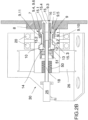
- Figs 2A-2B illustrate the demolition robot's robot arm 2 carrying a cut-off saw tool 3 with an exchangeable rotatable saw blade 5.
- the saw blade is typically a disc-shaped rotationally symmetrical saw blade with a hub 6 configured to be releasably mounted on an end portion 4.1 associated with the rotatable spindle 4 of the cut-off saw tool.
- the saw blade 5 with the hub 6 is releasably arranged on the spindle end portion 4.1 with a torque-transmitting connection 7.
- a release mechanism 30 for remote-controllable automatic exchange of the saw blade is arranged on the robot arm 2.
- the release mechanism 30, comprising a remote-controllable hydraulic cylinder, is arranged on the robot arm adjacent to the spindle and on the same side as the spindle relative to the saw blade.
- the saw blade hub 6 has a first end connected with the saw blade 5, a hub flange 8 connected with the saw blade 1 and a second end 9 facing the spindle 4.
- the second hub end 9 has the shape of a truncated cone with an outer conical envelope surface 9.1 with a decreasing diameter in the direction from the saw blade 5 and a plane end surface 9.2 in the radial plane.
- Fig. 2B shows that the hub end 9 is configured as an annular end portion 9.10, the outer conical envelope surface 9.1 of which is configured to cooperate shape-wise with an inner conical clamping surface 4.10 associated with the spindle, and wherein the hub end surface 9.2 abuts and shape-wise cooperates with an inner bearing surface 4.18 associated with the spindle at insertion of the hub 6 in the spindle end portion 4.1 to obtain a radially as well as axially correct position of the saw blade on the spindle.
- the saw blade hub has a central longitudinal opening 9.3, extending between the ends of the hub and having an inner limitation surface 9.4 with varying cross sections.
- the annular end portion 9.10 has a bearing surface 9.11 facing the rotational axis and configured to abut against an intermediate piece 12 associated with a blocking element 10, wherein the longitudinal opening 9.3 has a first inner diameter d1 along the bearing surface 9.11.
- the inner limitation surface 9.4 is enlarged in the radial direction within the second hub end 9 and forms an axially extended inner cavity 9.6 with a second inner diameter d2, which is larger than d1.
- the longitudinal opening 9.3 and inner cavity 9.6 of the hub are arranged to receive the blocking element 10 with a corresponding plurality of pawls 11 as well as a manoeuvring sleeve 15, wherein the blocking element 10 is adapted to be inserted through the longitudinal opening 9.3 ending at the second end 9 of the hub and to extend into the cavity 9.6 to couple together the hub of the saw blade with the spindle.
- the cut-off saw tool has a rotatable spindle 4, which is mounted in a bearing housing 20 arranged on the robot arm.
- the spindle has a first end 4.1 that protrudes from the bearing housing and is arranged adjacent to the hub 6.
- the first end 4.1 of the spindle has a first impact surface 4.17 in the radial plane (i.e. perpendicular to the rotational axis of the spindle), which is arranged to abut against the flange 8 associated with the hub as well as a receiving portion 4.5, which is configured as a notch at the spindle end 4.1.
- the receiving portion 4.5 has an inner conical clamping surface 4.10 connected with the impact surface 4.17 and an inner plane bearing surface 4.18 in the radial plane, which surrounds a central opening 4.15.
- the conical clamping surface 4.10 of the spindle is configured for receiving the hub of the saw blade and shape-wise cooperating with the outer conical envelope surface 9.1 associated with the hub and forming the torque-transmitting connection 7 configured as a conical clamping connection, which during operation of the cut-off saw tool transmits the emerging torque from the spindle to the blade.
- the first cavity 4.2 is intended to receive the sleeve-like blocking element 10 and has an inner limitation surface with varying form and cross section, which shape-wise corresponds to the configuration of the blocking element in order to, by rotational driving, retain the blocking element 10, which is integrated in the spindle and rotatable with the spindle.
- the cavity comprises a passage 4.6 with a reduced diameter connected to the receiving portion 4.5.
- the passage is arranged for receiving an intermediate piece 12 associated with the blocking element 10.
- the passage 4.6 is enlarged to an internal compartment arranged for receiving a rear end 13 of the blocking means.
- the internal compartment has an inner conical impact surface 4.4 intended to abut against the rear blocking means 13 of the blocking element.
- the first cavity 4.2 Adjacent to the partition wall 4.8, the first cavity 4.2 has a cylindrical compartment with a reduced cross section in comparison with the cross section of the internal compartment arranged for accommodating the rear end of the blocking element.
- the cylindrical compartment is configured for accommodating a compression spring 51 with as associated casing.
- the second cavity 4.3 closest to the second end of the spindle is cylindrical with a uniform cross section, wherein a tension spring 50 is arranged, which is connected with a pulling rod 18.
- the spindle has a second end 4.11 connected with the transmission, a belt pulley 26.
- the belt pulley is connected with a belt to a driving motor (not shown in the figure), so that the torque from the driving motor is transferred via the belt to the belt pulley 26, which is mounted on the spindle 4, so that the spindle is caused to rotate.
- the second end 4.11 of the spindle is facing a remote-controllable hydraulic cylinder 25, which is arranged to activate a release of the saw blade, when automatic exchange of the saw blade is to be executed.
- Fig. 2B shows the sleeve-like blocking element 10, which has a first end with a plurality of radially outwardly directed pawls 11 arranged around the circumference, and which are resiliently and radially manoeuvrable, and a second annular end with a least one radially outwardly directed rear blocking means 13 as well as an intermediate piece 12 that connects the first and the second end.
- the blocking element 10 is integrated in the spindle by being partially arranged within the first cavity 4.2 of the spindle.
- the blocking element has an axially directed central feed-through opening 14, in which a manoeuvring means 18 coupled to the manoeuvring sleeve 15 is inserted, whereby the manoeuvring sleeve 15 projects from the feed-through opening in the longitudinal cavity of the hub towards the saw blade.
- the rear blocking means 13 of the blocking element has an abutment surface that shape-wise cooperates with the cavity's inner conical impact surface 4.4 arranged in the internal compartment of the cavity and part of the intermediate piece 12 of the blocking element is arranged in the passage 4.6.
- the first end of the blocking element carrying the pawls 11 protrudes from the central opening 4.15 of the spindle to the receiving portion 4.5 of the spindle, so that the pawls 11 are arranged in an axial position between the inner bearing surface 4.18 of the spindle and the first impact surface 4.17.
- the blocking element is inserted through the longitudinal opening 9.3 of the hub to the enlarged inner cavity 9.6 at the second end 9 of the hub when a saw blade hub is inserted in the receiving portion 4.5 of the spindle.
- the function of the blocking element 10 is to couple the saw blade hub with the spindle 4 in a locked state, both radially and axially in a functional and reliable manner and block, prevent the saw blade hub 6 from being released from the spindle.
- the radially outwardly directed pawls 11 are resiliently and radially manoeuvrable and configured to engage with and capture the inner conical engagement surface of the hub.
- the manoeuvring sleeve is arranged, in an activated state, a locked state, to operate the blocking element 10 to releasably retain the saw blade hub by pressing the pawls radially outwards for engagement with the engagement surface 9.5 of the hub and thereby releasably retain the saw blade hub 6 against the spindle.
- the blocking element 10 and the manoeuvring sleeve 15 thereby apply a clamping force against the hub's inner engagement surface 9.5, which releasably clamps the saw blade hub 6 fixedly against the spindle 4 under the influence of a tension force along the manoeuvring means 18 for example generated by a tension spring 50, whereby a conical torque-transmitting clamping connection 7 is formed between the inner conical clamping surface 4.10 of the spindle and the outer conical envelope surface 9.1 of the hub.
- the saw blade 5 is releasably locked on the spindle with the torque-transmitting conical clamping connection 7 between the saw blade hub 6 and the spindle 4 in combination with the engagement surface 9.5 of the hub being captured by the pawls 11 and through inverse engagement of the hub end 9 around the blocking element 10 by the influence of a tension spring 50 or hydraulic cylinder 25, whereby the hub of the saw blade is connected by being clamped fixedly against the spindle.
- Figs 2A-B further show that the demolition robot comprises a release mechanism 30 for releasing or freeing the rotatable saw blade in a remote-controllable automatic exchange of the saw blade by the operator.
- the release mechanism comprises a remote-controllable hydraulic cylinder 25 arranged on the robot arm 2, a manoeuvring means 18 displaceably arranged on the spindle and a manoeuvring sleeve 15.
- the hydraulic cylinder is coupled to the manoeuvring sleeve 15 via the displaceable manoeuvring means.
- the manoeuvring means 18 consists of an elongated pulling rod coupled to the hydraulic piston of the hydraulic cylinder and extends along the rotational axis of the spindle through the cavity 4.2,4.3 of the spindle and through the drilled hole 4.20 of the partition wall, whereby the end facing the saw blade is coupled to the manoeuvring sleeve 15.
- the manoeuvring means is preferably inserted in a central opening 15.4 in the manoeuvring sleeve and thereby coupled to the manoeuvring sleeve.
- the manoeuvring means 18 is displaceably accommodated in the spindle along the rotational axis of the spindle to enable the execution of an automatic exchange of the saw blade.
- a tension spring 50 arranged in the second cavity 4.3 of the spindle is connected to the manoeuvring means to apply a tension force on the manoeuvring means 18 and the manoeuvring sleeve 15 to maintain the torque-transmitting conical clamping connection 7 during operation.
- Figs 2A-B further show that the end 4.1 of the spindle is coaxially arranged with the hub 6 and end 9 of the saw blade, the blocking element 10, the manoeuvring sleeve 15 and the manoeuvring means, whereby the blocking element further is coaxially arranged around the manoeuvring sleeve 15, so that the blocking element 10 is arranged between the inner limitation surface 9.4 of the hub and the manoeuvring sleeve.
- the end 4.1 of the spindle is coaxially arranged with the hub 6 and end 9 of the saw blade, the blocking element 10, the manoeuvring sleeve 15 and the manoeuvring means, whereby the blocking element further is coaxially arranged around the manoeuvring sleeve 15, so that the blocking element 10 is arranged between the inner limitation surface 9.4 of the hub and the manoeuvring sleeve.
- Figs 2A-B show that the manoeuvring sleeve 15 is arranged in the blocking element in the inner cavity of the spindle and has a first end 15.1 protruding towards the saw blade in the longitudinal opening 9.3 of the hub, and a second end 15.2, which is coaxially arranged and slidably displaceable in the feed-through opening 14 of the blocking element and is coupled to the manoeuvring means 18 as well as an intermediate piece 15.3, which connects the first and second ends of the manoeuvring sleeve.
- the manoeuvring sleeve has a longitudinal central opening 15.4 between the ends for receiving the manoeuvring means 18.
- the manoeuvring sleeve is cylindrical with a varying outer cross section, whereby the first end 15.1 has a larger diameter than the second end 15.2.
- the outer diameter of the first end is smaller than the inner diameter d1 of the hub to enable that the manoeuvring sleeve can be displaced out through the longitudinal opening 9.3 of the hub for picking an unused saw blade.
- the intermediate piece 15.3 of the manoeuvring sleeve is configured with an arched comb surface 16, arranged externally around the circumference, with a diameter that increases towards the saw blade, and which passes into a straight cylindrical surface along the first end.
- the manoeuvring sleeve is displaceably accommodated within the blocking element 10 and is displaceable through the longitudinal opening 9.3 of the hub.
- the manoeuvring sleeve can assume an activated state, a locking state, whereby the saw blade hub is caused to be releasably locked on the spindle or a deactivating release state, whereby the saw blade hub is caused to be released from the spindle.
- the comb surface 16 is arranged so that at displacement of the manoeuvring sleeve towards the spindle 4 under the influence of a tension force from the tension spring 50 to a first state, locking state, it can operate or press the pawls to be displaced in radially outward direction and lock them against the inner engagement surface 9.5 of the hub. In the locking state, the comb surface 16 acts actively for the radially resilient pawls 11 not to move radially inwards towards the rotational axis.
- the manoeuvring sleeve 15 is caused to be displaced or pressed forward through the blocking element 10 and the saw blade hub 6 towards the saw blade 5 under the influence of the hydraulic cylinder in order to assume a second state, a release state.
- the pawls 11 of the blocking element is caused to be released from the engagement surface 9.5, and the resilient pawls are caused to be radially displaced towards the rotational axis out of engagement with the hub, whereby the saw blade hub 6 is releasable and comes loose from the spindle 4.
- the release mechanism 30 further comprises a remote-controllable hydraulic cylinder 25 arranged on the robot arm in connection with the spindle, adjacent to the second end 4.11 of the spindle.
- the hydraulic cylinder is coupled to the manoeuvring sleeve 15 via the manoeuvring means 18.
- the hydraulic cylinder has a hydraulic piston, which can be single-acting or double-acting.
- the hydraulic cylinder can be activated via remote-control by the operator, so that automatic exchange of the saw blade is executed.
- the hydraulic piston in the hydraulic cylinder 25 is displaced, wherein the manoeuvring means 18 and the manoeuvring sleeve 15 are pressed to be displaced axially along the rotational axis towards the saw blade, wherein automatic release of the saw blade is executed, whereupon a new unused saw blade is picked and automatically attached to the spindle.
- a remote-controlled automatic exchange of saw blade on the saw tool arranged on the robot arm is executed according to a method, whereby a release mechanism 30 arranged on the robot arm 2 of the demolition robot is activated, and the torque-transmitting connection 7 between the spindle and the saw blade hub is released with the release mechanism.
- the used saw blade 5 is released with the release mechanism 30 from the spindle 4 and falls down, whereupon an unused saw blade 5' is picked with the end portion 4.1 of the spindle out of a cassette 60, containing at least one unused saw blade 5'.
- the picked saw blade 5' is attached and releasably locked with a torque-transmitting connection 7 to the end portion 4.1 of the spindle.
- the release mechanism 30 is activated e.g. via remote control and activation of the hydraulic cylinder 25 for action on the manoeuvring sleeve 15 for release of the torque-transmitting connection 7 by the activated hydraulic cylinder displacing the manoeuvring sleeve 15 towards the saw blade 5.
- the manoeuvring means 18 is by means of the hydraulic cylinder 25 pressed outwards towards the hub 6. This results in the pawls 11 being displaced out of engagement against the conical engagement surface 9.5 in the hub and allows the blade 5 to fall out of the receiving portion of the spindle.
- a new blade 5' is picked up from a pre-assembled cassette 60 and is locked e.g. by the hydraulic pressure on the hydraulic cylinder being drained to a tank or under the influence of the tension spring 50.
- the picked unused saw blade 5' is releasably locked with the torque-transmitting connection 7 to the end portion 4.1 of the spindle by a plurality of pawls 11 associated with the blocking element 10 cooperating and forming an inverse engagement with a conically shaped engagement surface 9.5 associated with the saw blade hub 6 under the influence of the tension spring 50 and/or the hydraulic cylinder 25.
- the picked unused saw blade 5' is connected, releasably locked, to the end portion 4.1 of the spindle with a manoeuvring means 18 that displaces the manoeuvring sleeve 15 in the direction from the saw blade 5 under the influence of a tension spring 50 and/or the hydraulic cylinder 25, whereby the manoeuvring sleeve 15 presses the blocking element against the engagement surface 9.5 internally arranged in the saw blade hub and an outer conical envelope surface 9.1 associated with the hub is connected with an inner conical clamping surface 4.10 associated with the spindle, so that the hub is clamped fixedly against the spindle.
Landscapes
- Engineering & Computer Science (AREA)
- Mechanical Engineering (AREA)
- Life Sciences & Earth Sciences (AREA)
- Architecture (AREA)
- Wood Science & Technology (AREA)
- Forests & Forestry (AREA)
- Robotics (AREA)
- Physics & Mathematics (AREA)
- Fluid Mechanics (AREA)
- Chemical & Material Sciences (AREA)
- Chemical Kinetics & Catalysis (AREA)
- Electrochemistry (AREA)
- Civil Engineering (AREA)
- Structural Engineering (AREA)
- Sawing (AREA)
- Working Measures On Existing Buildindgs (AREA)
Claims (13)
- Robot de démolition (1) comprenant un bras (2) équipé d'un outil de sciage (3) à lame de scie interchangeable (5), dans lequel l'outil de sciage comprend une broche rotative (4) dotée d'une extrémité (4.1) et la lame de scie comprend un moyeu (6), dans lequel le moyeu de lame de scie est disposé sur l'extrémité (4.1) de la broche avec une liaison de transmission de couple (7), caractérisé en ce qu'un mécanisme de libération (30) pour l'échange automatique de la lame de scie (5) est disposé sur le bras (2), dans lequel le mécanisme de libération (30) comprend un vérin hydraulique télécommandable (25) disposé sur le bras et un manchon de manœuvre (15) couplé au vérin hydraulique par un moyen de manœuvre mobile (18) disposé dans la broche (4), et la liaison de transmission de couple (7) est de forme conique, comprenant une surface d'enveloppe conique extérieure (9.1) associée au moyeu et une surface de serrage conique intérieure (4.10) associée à la broche,dans lequel le manchon de manœuvre (15) est agencé pour coopérer avec un élément de blocage (10) intégré dans la broche (4),dans lequel l'élément de blocage (10) comporte une première extrémité avec une pluralité de cliquets (11) dirigés radialement vers l'extérieur, disposés autour de la circonférence, et qui sont résilients et manœuvrables dans la direction radiale vers l'extérieur et configurés pour s'engager avec et capturer une surface d'engagement conique intérieure (9.5) du moyeu,dans lequel, dans un état de verrouillage, le manchon de manœuvre est agencé pour actionner l'élément de blocage (10) sous l'influence d'une force de tension le long du moyen de manœuvre (18), dans lequel l'élément de blocage (10) dans un état de verrouillage est agencé pour retenir de manière libérable le moyeu de lame de scie (6), en pressant les cliquets (11) radialement vers l'extérieur pour un engagement avec la surface d'engagement (9.5) du moyeu,dans lequel, dans un état de libération, le vérin hydraulique est activé, et le manchon de manœuvre (15) est amené à être déplacé ou pressé vers l'avant à travers l'élément de blocage (10) et le moyeu de lame de scie (6) vers la lame de scie (5), sous l'influence du vérin hydraulique, dans lequel l'élément de blocage est amené à libérer le moyeu (6) sous l'influence du manchon de manœuvre, et le moyeu de lame de scie (6) est amené à être libéré de la partie d'extrémité (4.1) de la broche, dans lequel la lame de scie se détache de la broche (4).
- Robot de démolition selon la revendication 1, dans lequel l'élément de blocage (10) est inséré dans une ouverture longitudinale (9.3) agencée dans le moyeu (6) de la lame de scie.
- Robot de démolition selon la revendication 2, dans lequel la surface d'engagement de forme conique (9.5) disposée à l'intérieur du moyeu de lame de scie est agencée pour coopérer par engagement inverse avec l'élément de blocage (10), la lame de scie (5) pouvant être retenue de manière amovible sur la broche (4).
- Robot de démolition selon la revendication 3, dans lequel les cliquets dans l'état de verrouillage sont pressés contre la surface d'engagement intérieure (9.5) du moyeu par le manchon de manœuvre (15) sous l'influence d'une force de tension agissant sur le moyen de manœuvre (18), dans lequel la liaison de serrage conique de transmission de couple (7) est formée.
- Robot de démolition selon la revendication 4, dans lequel, dans l'état de verrouillage, l'extrémité de broche (4.1) est disposée coaxialement avec le moyeu de lame de scie (6), le moyeu de lame de scie (6) étant disposé pour recevoir l'élément de blocage (10) avec la pluralité de cliquets (11) associés ainsi que le manchon de manœuvre (15), le moyeu de lame de scie étant disposé coaxialement et entoure l'élément de blocage (10) et le manchon de manœuvre (15), et l'élément de blocage (10) étant disposé entre le moyeu et le manchon de manœuvre.
- Robot de démolition selon la revendication 4 ou 5, dans lequel le manchon de manœuvre (15) est disposé de manière déplaçable dans l'élément de blocage (10) dans une cavité intérieure ménagée dans la broche, dans lequel le manchon de manœuvre (15) comprend une ouverture centrale longitudinale (15.4) pour recevoir le moyen de manœuvre (18) et est couplé au moyen de manœuvre (18), dans lequel le manchon de manœuvre est déplaçable à travers une ouverture de passage (14) agencée dans l'élément de blocage et est déplaçable à travers l'ouverture longitudinale (9.3) du moyeu vers la lame de scie, dans lequel le manchon de manœuvre est configuré avec une surface de peigne extérieure (16) agencée pour coopérer avec les cliquets (11) de l'élément de blocage.
- Robot de démolition selon la revendication 6, dans lequel la surface de peigne (16) du manchon de manœuvre est agencée, lors du déplacement du manchon de manœuvre (15) vers la broche (4) à un état de verrouillage, pour presser les cliquets à être déplacer dans la direction radiale vers l'extérieur et les verrouiller contre la surface d'engagement intérieure (9.5) du moyeu, dans lequel, dans un état de libération, lorsque le manchon de manœuvre (15) est déplacé vers la lame de scie (5), la surface de peigne est déplacée hors de contact avec les cliquets (11), qui sont ainsi libérés de la surface d'engagement (9.5), le moyeu de lame de scie (6) pouvant être libéré de la broche (4).
- Robot de démolition selon l'une quelconque des revendications précédentes 4 à 7, dans lequel, dans un état de verrouillage, la lame de scie (5) est verrouillée de manière amovible sur la broche (4) avec la liaison de serrage conique de transmission de couple (7), qui est formée entre le moyeu de lame de scie (6) et la broche (4) en combinaison avec la surface d'engagement (9.5) du moyeu qui est capturée par les cliquets (11) par l'engagement inverse de l'extrémité du moyeu (9) autour de l'élément de blocage (10) sous l'influence du manchon de manœuvre déplacé par un ressort de tension (50) ou le vérin hydraulique (25).
- Robot de démolition selon la revendication 8, dans lequel, dans un état de libération, le vérin hydraulique est activé, et le manchon de manœuvre est amené à se déplacer à travers la broche (4) et le moyeu de lame de scie (6) sous l'influence du vérin hydraulique, dans lequel les cliquets (11) de l'élément de blocage sont amenés à se libérer de l'engagement avec le moyeu (6), et la lame de scie est amenée à se libérer de la broche.
- Robot de démolition selon les revendications 8 ou 9, dans lequel le ressort de tension (50) est disposé dans la broche et est relié au moyen de manœuvre (18), le ressort de tension influençant le moyen de manœuvre et le manchon de manœuvre (15) avec une force de tension pour maintenir la liaison de serrage conique de transmission de couple (7).
- Procédé d'échange automatique et télécommandable d'une lame de scie (5) sur un outil de sciage (3) associé à un robot de démolition (1) selon la revendication 1, dans lequel la lame de scie (5) est disposée de manière amovible avec une liaison de transmission de couple (7) sur la broche associée à l'outil de sciage,
dans lequel le procédé comprend les étapes suivantes :- dans un état de libération, l'activation du mécanisme de libération (30) disposé sur le bras du robot de démolition par commande à distance du vérin hydraulique (25), moyennant quoi le vérin hydraulique déplace le manchon de manœuvre (15) vers la lame de scie- la libération de la liaison de transmission de couple (7) avec le mécanisme de libération (30) en libérant l'élément de blocage (10) du moyeu (6) sous l'effet du manchon de manœuvre, provoquant la libération du moyeu de la lame de scie (6) de la partie d'extrémité (4.1) de la broche, de sorte que la lame de scie usagée est libérée et tombe de la broche,- le prélèvement d'une lame de scie (5') non utilisée avec la broche (4) d'une cassette (60), comprenant au moins une lame de scie (5') non utilisée,- dans un état de verrouillage, la lame de scie non utilisée (5') prélevée est reliée de manière amovible à la partie d'extrémité (4.1) de la broche par une liaison de transmission de couple (7) par l'intermédiaire de l'élément de blocage (10) intégré dans la broche (4) qui est amené en prise de retenue amovible avec le moyeu de lame de scie (6) sous l'effet du déplacement du manchon de manœuvre en direction de la lame de scie par un ressort de traction (50) et/ou le vérin hydraulique (25). - Procédé selon la revendication 11, dans lequel l'élément de blocage (10) est agencé pour coopérer par un engagement inverse avec le moyeu de lame de scie (6).
- Procédé selon l'une quelconque des revendications 11 à 12, dans lequel le manchon de manœuvre (15) presse l'élément de blocage (10) contre la surface d'engagement (9.5) disposée à l'intérieur du moyeu de lame de scie (6), de sorte que le moyeu est serré de manière fixe contre la partie d'extrémité (4.1) de la broche par la surface d'enveloppe conique extérieure (9.1) associée au moyeu qui est connectée à la surface de serrage conique intérieure (4.10) associée à la broche et forme la connexion de serrage conique de transmission de couple (7).
Applications Claiming Priority (2)
| Application Number | Priority Date | Filing Date | Title |
|---|---|---|---|
| SE2050210A SE544796C2 (sv) | 2020-02-25 | 2020-02-25 | Fjärrstyrbar demoleringsrobot med ett sågvektyg samt förfarande för fjärrstyrbart automatiskt utbyte av sågklinga på sågverktyget |
| PCT/SE2021/050160 WO2021173067A1 (fr) | 2020-02-25 | 2021-02-25 | Robot de démolition |
Publications (3)
| Publication Number | Publication Date |
|---|---|
| EP4110561A1 EP4110561A1 (fr) | 2023-01-04 |
| EP4110561A4 EP4110561A4 (fr) | 2024-03-06 |
| EP4110561B1 true EP4110561B1 (fr) | 2025-06-25 |
Family
ID=77490268
Family Applications (1)
| Application Number | Title | Priority Date | Filing Date |
|---|---|---|---|
| EP21760853.8A Active EP4110561B1 (fr) | 2020-02-25 | 2021-02-25 | Robot de démolition |
Country Status (5)
| Country | Link |
|---|---|
| US (1) | US12208533B2 (fr) |
| EP (1) | EP4110561B1 (fr) |
| CN (1) | CN115151390B (fr) |
| SE (1) | SE544796C2 (fr) |
| WO (1) | WO2021173067A1 (fr) |
Families Citing this family (3)
| Publication number | Priority date | Publication date | Assignee | Title |
|---|---|---|---|---|
| DE102023120300A1 (de) * | 2023-07-31 | 2025-02-06 | HELLA GmbH & Co. KGaA | Vorrichtung und Verfahren zur automatisierten Herstellung von Schraubverbindungen |
| FR3158328B1 (fr) * | 2024-01-12 | 2026-02-13 | Vinci Construction | Procédé de démolition d'une structure bâtie |
| CN119681343B (zh) * | 2025-01-15 | 2025-07-11 | 江苏路乔金属科技有限公司 | 一种无缝钢管端头切断设备 |
Family Cites Families (14)
| Publication number | Priority date | Publication date | Assignee | Title |
|---|---|---|---|---|
| DE3142102A1 (de) * | 1981-10-23 | 1983-05-05 | Maschinenfabrik Böhl GmbH, 5920 Bad Berleburg | Klemmvorrichtung fuer saegeblaetter |
| JPS59175984A (ja) * | 1983-03-22 | 1984-10-05 | フアナツク株式会社 | 工業用ロボツトのハンド交換装置 |
| US4897014A (en) * | 1988-09-06 | 1990-01-30 | Harbor Branch Oceanographic Institution, Inc. | Device for interchange of tools |
| US5676125A (en) * | 1995-06-23 | 1997-10-14 | Kelly; Patrick | Excavator mounted concrete saw |
| JPH11235609A (ja) * | 1998-02-19 | 1999-08-31 | Toshiba Mach Co Ltd | 回転駆動型工具 |
| JP3525742B2 (ja) * | 1998-06-11 | 2004-05-10 | 日産自動車株式会社 | ツールポットのツールホルダ保持装置 |
| FR2863519B1 (fr) | 2003-12-11 | 2006-01-21 | Snecma Moteurs | Dispositif de montage et de demontage automatiques d'outils sur un automate |
| CN101262971B (zh) * | 2005-09-13 | 2013-08-21 | 罗姆股份有限公司 | 用于使操纵单元运行的方法以及用于执行该方法的装置 |
| JP5275044B2 (ja) * | 2007-01-09 | 2013-08-28 | 株式会社マキタ | 回転刃具の固定装置 |
| DE102009034275A1 (de) * | 2009-07-21 | 2011-01-27 | Georg Prinzing Gmbh & Co Kg Betonformen- Und Maschinenfabrik | Verfahren und Vorrichtung zum Wechseln von Fräsern an einem Industrieroboter |
| SE539241C2 (en) * | 2015-10-19 | 2017-05-23 | Husqvarna Ab | Adaptive control of hydraulic tool on remote demolition robot |
| DE102017107488A1 (de) * | 2017-04-07 | 2018-10-11 | Ott-Jakob Spanntechnik Gmbh | Spannvorrichtung und Bearbeitungseinheit mit einer derartigen Spannvorrichtung |
| CN207668542U (zh) * | 2017-12-22 | 2018-07-31 | 深圳市兴旺达科技有限公司 | 一种新型简易型hsk拉爪组件 |
| JP6650171B1 (ja) * | 2018-12-26 | 2020-02-19 | 株式会社ファインテクノ | 加工工具の刃具交換装置 |
-
2020
- 2020-02-25 SE SE2050210A patent/SE544796C2/sv unknown
-
2021
- 2021-02-25 WO PCT/SE2021/050160 patent/WO2021173067A1/fr not_active Ceased
- 2021-02-25 US US17/904,839 patent/US12208533B2/en active Active
- 2021-02-25 CN CN202180016211.2A patent/CN115151390B/zh active Active
- 2021-02-25 EP EP21760853.8A patent/EP4110561B1/fr active Active
Also Published As
| Publication number | Publication date |
|---|---|
| CN115151390B (zh) | 2026-04-14 |
| US12208533B2 (en) | 2025-01-28 |
| EP4110561A1 (fr) | 2023-01-04 |
| WO2021173067A1 (fr) | 2021-09-02 |
| CN115151390A (zh) | 2022-10-04 |
| SE544796C2 (sv) | 2022-11-15 |
| EP4110561A4 (fr) | 2024-03-06 |
| SE2050210A1 (sv) | 2021-08-26 |
| US20230103522A1 (en) | 2023-04-06 |
Similar Documents
| Publication | Publication Date | Title |
|---|---|---|
| EP4110561B1 (fr) | Robot de démolition | |
| US6415875B1 (en) | Hand-held power tool | |
| US2987334A (en) | Tool holders | |
| KR101931380B1 (ko) | 고주파 스핀들 | |
| US6691799B2 (en) | Tool holder | |
| JPH01193164A (ja) | 自動ロック作用をもつ作動スピンドルを具備する可搬形工作機械 | |
| EP1436117B1 (fr) | Outil mecanique portable a arbre de sortie rotatif et dispositif de securite contre les surcharges | |
| JPS6055275B2 (ja) | 工具保持体 | |
| EP1156899B1 (fr) | Outil a riveter | |
| GB2079643A (en) | Mine roof drill and drive member connection | |
| KR20080000616A (ko) | 건설 중장비의 소재 취급 장치에서 마모 부분을 그것의지지부에 연결하는 방법 및 장치 | |
| US11945088B2 (en) | Hand-held power tool having a locking device | |
| EP3061575B1 (fr) | Machine-outil portative | |
| WO2009018341A2 (fr) | Riveteuse pneumatique | |
| EP0198105A1 (fr) | Tendeur en forme de fil pointu facilement démontable, à utiliser avec des outils automatiques à insérer et à extraire | |
| DE102014207713A1 (de) | Werkzeugvorsatz für eine Handwerkzeugmaschine | |
| GB1579917A (en) | Machine tool with a rotatable spindle and a tool holder | |
| JP4662687B2 (ja) | 取り外し可能な工具保持体を備えた手持ち工作機械 | |
| EP4227040A1 (fr) | Dispositif de serrage et machine-outil portative | |
| MX2010008988A (es) | Conexion con anillo de seguridad. | |
| US6799502B2 (en) | Spring brake cylinder with an emergency release device | |
| EP1795307A2 (fr) | Adaptateur pour un outil à impact motorisé | |
| JPS61252921A (ja) | クラツチ解結機構 | |
| GB2098528A (en) | A power tool | |
| JPH026005A (ja) | 圧延機のロール組立体 |
Legal Events
| Date | Code | Title | Description |
|---|---|---|---|
| STAA | Information on the status of an ep patent application or granted ep patent |
Free format text: STATUS: THE INTERNATIONAL PUBLICATION HAS BEEN MADE |
|
| PUAI | Public reference made under article 153(3) epc to a published international application that has entered the european phase |
Free format text: ORIGINAL CODE: 0009012 |
|
| STAA | Information on the status of an ep patent application or granted ep patent |
Free format text: STATUS: REQUEST FOR EXAMINATION WAS MADE |
|
| 17P | Request for examination filed |
Effective date: 20220906 |
|
| AK | Designated contracting states |
Kind code of ref document: A1 Designated state(s): AL AT BE BG CH CY CZ DE DK EE ES FI FR GB GR HR HU IE IS IT LI LT LU LV MC MK MT NL NO PL PT RO RS SE SI SK SM TR |
|
| DAV | Request for validation of the european patent (deleted) | ||
| DAX | Request for extension of the european patent (deleted) | ||
| A4 | Supplementary search report drawn up and despatched |
Effective date: 20240207 |
|
| RIC1 | Information provided on ipc code assigned before grant |
Ipc: B27B 5/10 20060101ALI20240201BHEP Ipc: B25J 11/00 20060101ALI20240201BHEP Ipc: B23D 45/00 20060101ALI20240201BHEP Ipc: E04G 23/08 20060101ALI20240201BHEP Ipc: B27B 5/32 20060101ALI20240201BHEP Ipc: B25J 15/04 20060101AFI20240201BHEP |
|
| GRAP | Despatch of communication of intention to grant a patent |
Free format text: ORIGINAL CODE: EPIDOSNIGR1 |
|
| STAA | Information on the status of an ep patent application or granted ep patent |
Free format text: STATUS: GRANT OF PATENT IS INTENDED |
|
| INTG | Intention to grant announced |
Effective date: 20250120 |
|
| GRAS | Grant fee paid |
Free format text: ORIGINAL CODE: EPIDOSNIGR3 |
|
| GRAA | (expected) grant |
Free format text: ORIGINAL CODE: 0009210 |
|
| STAA | Information on the status of an ep patent application or granted ep patent |
Free format text: STATUS: THE PATENT HAS BEEN GRANTED |
|
| AK | Designated contracting states |
Kind code of ref document: B1 Designated state(s): AL AT BE BG CH CY CZ DE DK EE ES FI FR GB GR HR HU IE IS IT LI LT LU LV MC MK MT NL NO PL PT RO RS SE SI SK SM TR |
|
| REG | Reference to a national code |
Ref country code: GB Ref legal event code: FG4D |
|
| REG | Reference to a national code |
Ref country code: CH Ref legal event code: EP |
|
| REG | Reference to a national code |
Ref country code: DE Ref legal event code: R096 Ref document number: 602021032914 Country of ref document: DE |
|
| REG | Reference to a national code |
Ref country code: CH Ref legal event code: EP |
|
| P01 | Opt-out of the competence of the unified patent court (upc) registered |
Free format text: CASE NUMBER: APP_27738/2025 Effective date: 20250611 |
|
| REG | Reference to a national code |
Ref country code: IE Ref legal event code: FG4D |
|
| PG25 | Lapsed in a contracting state [announced via postgrant information from national office to epo] |
Ref country code: FI Free format text: LAPSE BECAUSE OF FAILURE TO SUBMIT A TRANSLATION OF THE DESCRIPTION OR TO PAY THE FEE WITHIN THE PRESCRIBED TIME-LIMIT Effective date: 20250625 |
|
| REG | Reference to a national code |
Ref country code: LT Ref legal event code: MG9D |
|
| PG25 | Lapsed in a contracting state [announced via postgrant information from national office to epo] |
Ref country code: NO Free format text: LAPSE BECAUSE OF FAILURE TO SUBMIT A TRANSLATION OF THE DESCRIPTION OR TO PAY THE FEE WITHIN THE PRESCRIBED TIME-LIMIT Effective date: 20250925 Ref country code: GR Free format text: LAPSE BECAUSE OF FAILURE TO SUBMIT A TRANSLATION OF THE DESCRIPTION OR TO PAY THE FEE WITHIN THE PRESCRIBED TIME-LIMIT Effective date: 20250926 |
|
| PG25 | Lapsed in a contracting state [announced via postgrant information from national office to epo] |
Ref country code: BG Free format text: LAPSE BECAUSE OF FAILURE TO SUBMIT A TRANSLATION OF THE DESCRIPTION OR TO PAY THE FEE WITHIN THE PRESCRIBED TIME-LIMIT Effective date: 20250625 |
|
| PG25 | Lapsed in a contracting state [announced via postgrant information from national office to epo] |
Ref country code: HR Free format text: LAPSE BECAUSE OF FAILURE TO SUBMIT A TRANSLATION OF THE DESCRIPTION OR TO PAY THE FEE WITHIN THE PRESCRIBED TIME-LIMIT Effective date: 20250625 |
|
| PG25 | Lapsed in a contracting state [announced via postgrant information from national office to epo] |
Ref country code: RS Free format text: LAPSE BECAUSE OF FAILURE TO SUBMIT A TRANSLATION OF THE DESCRIPTION OR TO PAY THE FEE WITHIN THE PRESCRIBED TIME-LIMIT Effective date: 20250925 |
|
| PG25 | Lapsed in a contracting state [announced via postgrant information from national office to epo] |
Ref country code: LV Free format text: LAPSE BECAUSE OF FAILURE TO SUBMIT A TRANSLATION OF THE DESCRIPTION OR TO PAY THE FEE WITHIN THE PRESCRIBED TIME-LIMIT Effective date: 20250625 |
|
| REG | Reference to a national code |
Ref country code: NL Ref legal event code: MP Effective date: 20250625 |
|
| PG25 | Lapsed in a contracting state [announced via postgrant information from national office to epo] |
Ref country code: NL Free format text: LAPSE BECAUSE OF FAILURE TO SUBMIT A TRANSLATION OF THE DESCRIPTION OR TO PAY THE FEE WITHIN THE PRESCRIBED TIME-LIMIT Effective date: 20250625 |
|
| PG25 | Lapsed in a contracting state [announced via postgrant information from national office to epo] |
Ref country code: PT Free format text: LAPSE BECAUSE OF FAILURE TO SUBMIT A TRANSLATION OF THE DESCRIPTION OR TO PAY THE FEE WITHIN THE PRESCRIBED TIME-LIMIT Effective date: 20251027 |
|
| REG | Reference to a national code |
Ref country code: AT Ref legal event code: MK05 Ref document number: 1806006 Country of ref document: AT Kind code of ref document: T Effective date: 20250625 |
|
| PG25 | Lapsed in a contracting state [announced via postgrant information from national office to epo] |
Ref country code: IS Free format text: LAPSE BECAUSE OF FAILURE TO SUBMIT A TRANSLATION OF THE DESCRIPTION OR TO PAY THE FEE WITHIN THE PRESCRIBED TIME-LIMIT Effective date: 20251025 |
|
| PGFP | Annual fee paid to national office [announced via postgrant information from national office to epo] |
Ref country code: GB Payment date: 20251211 Year of fee payment: 6 |
|
| PG25 | Lapsed in a contracting state [announced via postgrant information from national office to epo] |
Ref country code: AT Free format text: LAPSE BECAUSE OF FAILURE TO SUBMIT A TRANSLATION OF THE DESCRIPTION OR TO PAY THE FEE WITHIN THE PRESCRIBED TIME-LIMIT Effective date: 20250625 Ref country code: SM Free format text: LAPSE BECAUSE OF FAILURE TO SUBMIT A TRANSLATION OF THE DESCRIPTION OR TO PAY THE FEE WITHIN THE PRESCRIBED TIME-LIMIT Effective date: 20250625 |
|
| PGFP | Annual fee paid to national office [announced via postgrant information from national office to epo] |
Ref country code: FR Payment date: 20251209 Year of fee payment: 6 |
|
| PG25 | Lapsed in a contracting state [announced via postgrant information from national office to epo] |
Ref country code: CZ Free format text: LAPSE BECAUSE OF FAILURE TO SUBMIT A TRANSLATION OF THE DESCRIPTION OR TO PAY THE FEE WITHIN THE PRESCRIBED TIME-LIMIT Effective date: 20250625 |
|
| PG25 | Lapsed in a contracting state [announced via postgrant information from national office to epo] |
Ref country code: PL Free format text: LAPSE BECAUSE OF FAILURE TO SUBMIT A TRANSLATION OF THE DESCRIPTION OR TO PAY THE FEE WITHIN THE PRESCRIBED TIME-LIMIT Effective date: 20250625 |
|
| PG25 | Lapsed in a contracting state [announced via postgrant information from national office to epo] |
Ref country code: EE Free format text: LAPSE BECAUSE OF FAILURE TO SUBMIT A TRANSLATION OF THE DESCRIPTION OR TO PAY THE FEE WITHIN THE PRESCRIBED TIME-LIMIT Effective date: 20250625 |
|
| PG25 | Lapsed in a contracting state [announced via postgrant information from national office to epo] |
Ref country code: SK Free format text: LAPSE BECAUSE OF FAILURE TO SUBMIT A TRANSLATION OF THE DESCRIPTION OR TO PAY THE FEE WITHIN THE PRESCRIBED TIME-LIMIT Effective date: 20250625 |
|
| PG25 | Lapsed in a contracting state [announced via postgrant information from national office to epo] |
Ref country code: ES Free format text: LAPSE BECAUSE OF FAILURE TO SUBMIT A TRANSLATION OF THE DESCRIPTION OR TO PAY THE FEE WITHIN THE PRESCRIBED TIME-LIMIT Effective date: 20250625 |
|
| PG25 | Lapsed in a contracting state [announced via postgrant information from national office to epo] |
Ref country code: DK Free format text: LAPSE BECAUSE OF FAILURE TO SUBMIT A TRANSLATION OF THE DESCRIPTION OR TO PAY THE FEE WITHIN THE PRESCRIBED TIME-LIMIT Effective date: 20250625 |
|
| PGFP | Annual fee paid to national office [announced via postgrant information from national office to epo] |
Ref country code: DE Payment date: 20260129 Year of fee payment: 6 |
|
| PG25 | Lapsed in a contracting state [announced via postgrant information from national office to epo] |
Ref country code: IT Free format text: LAPSE BECAUSE OF FAILURE TO SUBMIT A TRANSLATION OF THE DESCRIPTION OR TO PAY THE FEE WITHIN THE PRESCRIBED TIME-LIMIT Effective date: 20250625 |
|
| PLBE | No opposition filed within time limit |
Free format text: ORIGINAL CODE: 0009261 |
|
| STAA | Information on the status of an ep patent application or granted ep patent |
Free format text: STATUS: NO OPPOSITION FILED WITHIN TIME LIMIT |