EP4110651B1 - Procédé de commande d'un modèle d'éclairage et dispositif d'éclairage d'automobile - Google Patents
Procédé de commande d'un modèle d'éclairage et dispositif d'éclairage d'automobile Download PDFInfo
- Publication number
- EP4110651B1 EP4110651B1 EP21706939.2A EP21706939A EP4110651B1 EP 4110651 B1 EP4110651 B1 EP 4110651B1 EP 21706939 A EP21706939 A EP 21706939A EP 4110651 B1 EP4110651 B1 EP 4110651B1
- Authority
- EP
- European Patent Office
- Prior art keywords
- light
- boundary
- width
- shifting
- column
- Prior art date
- Legal status (The legal status is an assumption and is not a legal conclusion. Google has not performed a legal analysis and makes no representation as to the accuracy of the status listed.)
- Active
Links
Images


Classifications
-
- B—PERFORMING OPERATIONS; TRANSPORTING
- B60—VEHICLES IN GENERAL
- B60Q—ARRANGEMENT OF SIGNALLING OR LIGHTING DEVICES, THE MOUNTING OR SUPPORTING THEREOF OR CIRCUITS THEREFOR, FOR VEHICLES IN GENERAL
- B60Q1/00—Arrangement of optical signalling or lighting devices, the mounting or supporting thereof or circuits therefor
- B60Q1/02—Arrangement of optical signalling or lighting devices, the mounting or supporting thereof or circuits therefor the devices being primarily intended to illuminate the way ahead or to illuminate other areas of way or environments
- B60Q1/04—Arrangement of optical signalling or lighting devices, the mounting or supporting thereof or circuits therefor the devices being primarily intended to illuminate the way ahead or to illuminate other areas of way or environments the devices being headlights
- B60Q1/06—Arrangement of optical signalling or lighting devices, the mounting or supporting thereof or circuits therefor the devices being primarily intended to illuminate the way ahead or to illuminate other areas of way or environments the devices being headlights adjustable, e.g. remotely-controlled from inside vehicle
- B60Q1/08—Arrangement of optical signalling or lighting devices, the mounting or supporting thereof or circuits therefor the devices being primarily intended to illuminate the way ahead or to illuminate other areas of way or environments the devices being headlights adjustable, e.g. remotely-controlled from inside vehicle automatically
- B60Q1/12—Arrangement of optical signalling or lighting devices, the mounting or supporting thereof or circuits therefor the devices being primarily intended to illuminate the way ahead or to illuminate other areas of way or environments the devices being headlights adjustable, e.g. remotely-controlled from inside vehicle automatically due to steering position
- B60Q1/122—Arrangement of optical signalling or lighting devices, the mounting or supporting thereof or circuits therefor the devices being primarily intended to illuminate the way ahead or to illuminate other areas of way or environments the devices being headlights adjustable, e.g. remotely-controlled from inside vehicle automatically due to steering position with electrical actuating means
-
- F—MECHANICAL ENGINEERING; LIGHTING; HEATING; WEAPONS; BLASTING
- F21—LIGHTING
- F21S—NON-PORTABLE LIGHTING DEVICES; SYSTEMS THEREOF; VEHICLE LIGHTING DEVICES SPECIALLY ADAPTED FOR VEHICLE EXTERIORS
- F21S41/00—Illuminating devices specially adapted for vehicle exteriors, e.g. headlamps
- F21S41/60—Illuminating devices specially adapted for vehicle exteriors, e.g. headlamps characterised by a variable light distribution
-
- F—MECHANICAL ENGINEERING; LIGHTING; HEATING; WEAPONS; BLASTING
- F21—LIGHTING
- F21W—INDEXING SCHEME ASSOCIATED WITH SUBCLASSES F21K, F21L, F21S and F21V, RELATING TO USES OR APPLICATIONS OF LIGHTING DEVICES OR SYSTEMS
- F21W2102/00—Exterior vehicle lighting devices for illuminating purposes
- F21W2102/10—Arrangement or contour of the emitted light
- F21W2102/17—Arrangement or contour of the emitted light for regions other than high beam or low beam
- F21W2102/19—Arrangement or contour of the emitted light for regions other than high beam or low beam for curves
Definitions
- This invention is related to the field of automotive lighting devices, and more particularly, to the way light patterns are managed when using a Dynamic Bending Light (DBL) functionality.
- DBL Dynamic Bending Light
- Dynamic Bending Lights are increasingly present in current automotive lighting devices, becoming an upgrade to standard headlights and designed to make driving at night easier and safer.
- Mechanic-based solutions turn the lighting source as the steering wheel does, by means of an angular movement converter which directly uses the turning of the steering wheel to induce a turning in the lighting source.
- the lights will turn in whatever direction the wheel does, and this range of motion allows the lights to illuminate the road even when taking sharp turns or turning quickly.
- the invention provides an alternative solution for this problem by a method for controlling a light pattern provided by an automotive lighting device of an automotive vehicle according to claim 1.
- This method provides a controlled light pattern which includes a Dynamic Bending Light functionality, provided by the same lighting device that provides, for example, the low beam and/or the high beam functionalities, without moving parts and also being able to adapt to other driving circumstances, such as the driving speed or the presence of cars in the opposite direction.
- a Dynamic Bending Light functionality provided by the same lighting device that provides, for example, the low beam and/or the high beam functionalities, without moving parts and also being able to adapt to other driving circumstances, such as the driving speed or the presence of cars in the opposite direction.
- the method considers that the lighting device is able to project a matrix arrangement of light pixels, forming a light pattern, which can be done in many different ways, as the skilled person will know.
- the method is not restricted to any of them.
- the light pattern is divided into portions. At least two portions, the first one and the second one, are identified. Each of these two portions have columns which are located in the edge of the portion, so they are adjacent to the following portion. These columns are called boundary columns.
- the method comprises the shifting of the boundary columns, thus involving a change in the width of the portions. This shifting movement leads to a “compression” or “expansion” of the columns of pixels which are inside the corresponding portion.
- the shifting in the operation should be understood as displacing the column to the right or to the left, depending on the receiving bending light command: if the original pattern in one row is, e.g., 0-0-0-0-1-1-0, and this row is divided into two portions 0-0-0-0-1 and 1-0, after a 1 column shift to the left, the width of the first portion will be reduced, thus leading to 0-0-0-1, and the width of the second portion will be enlarged, thus leading to 1-0-0.
- the luminous intensity values of the remaining pixels will be duly interpolated.
- These particular embodiments comprise a particular example of such an interpolation, which may be clarified with a more complex example. If a light pattern is provided 0-10-25-40-80-80-70-60-50-40-20-0, and is divided into two portions 0-10-25-40-80 and 80-70-60-50-40-20-0, the first portion will have a boundary value of 80 (the value of the boundary pixel) and an end value of 0 (the value of the end pixel, which is opposite to the boundary pixel) and the second portion will have a boundary value of 80 (the value of the boundary pixel) and an end value of 0 (the value of the end pixel, which is opposite to the boundary pixel).
- the shifting step comprises, e.g., 2 pixels to the right
- the result in the first portion will be 0-x-x-x-x-x-80 (since the end value and the boundary value preserves its luminous intensity value, but now the portion includes two more pixels) and the result in the second portion will be 80-x-x-x-0 (since the end value and the boundary value preserves its luminous intensity value, but now the portion includes two less pixels).
- the interpolation of the new values is made by a bilinear method or a nearest neighbour method.
- the bilinear method considers a first set of values with a first width and a final width, where this set of values should be converted to.
- the first width is defined by a first number of pixels (N1) and the final width is defined by a final number of pixels (N2), which can be higher or lower than the first number of pixels.
- a virtual abscissa segment [0, 1] is divided into N1-1 intervals, according to the first number of pixels.
- the ordinate values for the abscissa values are the values of the first set of values. Since they are discrete values, linear interpolations between vertices are provided. Then the same virtual interval is divided into N2-1 intervals, thus providing different abscissa values, but all of them also contained between 0 and 1.
- the final abscissa values will find a correspondent value in the continuous function. These values will be the values of the final set of data. For example, the first set of values is (1 3 4 8 10), so the first width is 5, since there are 5 values. The final width is 9.
- a function is defined by the vertices defined by the following pairs abscissa-ordinate: (0, 1), (0.25, 3), (0.5, 4), (0.75, 8), (1, 10). Linear interpolations are established between vertices.
- the function values for these abscissa values are located, which will be (1 1.5 3 3.5 4 6 8 9 10), so these will be the values of the final set of data.
- the bending light command comprises a number of positions to shift and a shifting direction, and then the step of shifting the position of the boundary columns is carried out using this number of positions to shift in the shifting direction.
- the matrix of solid-state light sources may have many different angular resolutions. Depending on the number and arrangement of these light sources, resolution may vary from 0.01° per light source up to 0.5° per light source. Hence, the angular position of the steering wheel may be translated in a different number of columns of the light array, depending on the density of these light sources in the array arrangement.
- the light pattern is divided into two portions and the division is performed so half of the light columns belong to the first portion and the other half to the second portion.
- the light pattern is divided into at least the first portion, the second portion and a central portion, wherein
- a central portion must be preserved without compression or expansion, due to light requirements (intensity or shape of the cut-off portion).
- This central portion is located between the first and the second portions, so it will have a first boundary column adjacent to the first portion and a second boundary column adjacent to the second portion.
- the shifting step does not affect to the width of the central portion, the intensity values are only shifted, but do not vary.
- the light pattern is a low beam pattern comprising a kink zone and the central portion contains the kink zone.
- the cut-off or kink is a diagonal line of the low beam pattern, and its shape is important in automotive regulations.
- the fact that this kink belongs to the central portion means that this kink is being shifted when the vehicle turns. This is advantageous since the shifted pattern must also comply with the regulations.
- the light pattern is a high beam pattern comprising a maximum luminous intensity pixel and the central portion contains the maximum luminous intensity pixel.
- the maximum intensity zone is also an advantageous zone to be protected in the central zone.
- the width of the central portion is chosen so that the first portion and the right portion have the same luminous flux.
- the width of the central portion may be chosen, parting from a particular zone to be protected, it may extend more to the left or to the right to compensate the flux difference between the first and second portions. This means that the final flux will remain constant after the shifting step.
- the invention provides an automotive lighting device comprising
- This automotive lighting device is configured to provide a Dynamic Bending Light functionality without moving parts, and using elements which are already available, but with a new configuration.
- solid state refers to light emitted by solid-state electroluminescence, which uses semiconductors to convert electricity into light. Compared to incandescent lighting, solid state lighting creates visible light with reduced heat generation and less energy dissipation.
- the typically small mass of a solid-state electronic lighting device provides for greater resistance to shock and vibration compared to brittle glass tubes/bulbs and long, thin filament wires. They also eliminate filament evaporation, potentially increasing the life span of the illumination device.
- Some examples of these types of lighting comprise semiconductor light-emitting diodes (LEDs), organic light-emitting diodes (OLED), or polymer light-emitting diodes (PLED) as sources of illumination rather than electrical filaments, plasma or gas.
- the matrix arrangement comprises at least 2000 solid-state light sources.
- This invention can be useful for many types of lighting matrix/array-based technology, from the simplest one, with only a few thousands light sources, to more advanced ones, with several hundred thousand light sources.
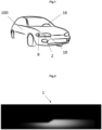
- Figure 1 shows a general perspective view of an automotive vehicle 100 comprising an automotive lighting device 10 according to the invention.
- This automotive vehicle 100 comprises a steering system 16 and a lighting device 10.
- the lighting device 10 comprises a matrix arrangement of LEDs 2 and a control centre 9 which is configured to control the operation of these groups of LEDs.
- the control centre 9 is configured to modify the configuration of the LEDs 2 when the steering wheel of the vehicle is activated.
- the matrix configuration is a high-resolution module, having a resolution greater than 2000 pixels. However, no restriction is attached to the technology used for producing the projection modules.
- a first example of this matrix configuration comprises a monolithic source.
- This monolithic source comprises a matrix of monolithic electroluminescent elements arranged in several columns by several rows.
- the electroluminescent elements can be grown from a common substrate and are electrically connected to be selectively activatable either individually or by a subset of electroluminescent elements.
- the substrate may be predominantly made of a semiconductor material.
- the substrate may comprise one or more other materials, for example non-semiconductors (metals and insulators).
- each electroluminescent element/group can form a light pixel and can therefore emit light when its/their material is supplied with electricity.
- the configuration of such a monolithic matrix allows the arrangement of selectively activatable pixels very close to each other, compared to conventional light-emitting diodes intended to be soldered to printed circuit boards.
- the monolithic matrix may comprise electroluminescent elements whose main dimension of height, measured perpendicularly to the common substrate, is substantially equal to one micrometre.
- the monolithic matrix is coupled to the control centre so as to control the generation and/or the projection of a pixelated light beam by the matrix arrangement 6.
- the control centre is thus able to individually control the light emission of each pixel of the matrix arrangement.
- the matrix arrangement 6 may comprise a main light source coupled to a matrix of mirrors.
- the pixelated light source is formed by the assembly of at least one main light source formed of at least one light emitting diode emitting light and an array of optoelectronic elements, for example a matrix of micro-mirrors, also known by the acronym DMD, for "Digital Micro-mirror Device", which directs the light rays from the main light source by reflection to a projection optical element.
- DMD Digital Micro-mirror Device
- an auxiliary optical element can collect the rays of at least one light source to focus and direct them to the surface of the micro-mirror array.
- Each micro-mirror can pivot between two fixed positions, a first position in which the light rays are reflected towards the projection optical element, and a second position in which the light rays are reflected in a different direction from the projection optical element.
- the two fixed positions are oriented in the same manner for all the micro-mirrors and form, with respect to a reference plane supporting the matrix of micro-mirrors, a characteristic angle of the matrix of micro-mirrors defined in its specifications. Such an angle is generally less than 20° and may be usually about 12°.
- each micro-mirror reflecting a part of the light beams which are incident on the matrix of micro-mirrors forms an elementary emitter of the pixelated light source.
- the actuation and control of the change of position of the mirrors for selectively activating this elementary emitter to emit or not an elementary light beam is controlled by the control centre.
- the matrix arrangement may comprise a scanning laser system wherein a laser light source emits a laser beam towards a scanning element which is configured to explore the surface of a wavelength converter with the laser beam. An image of this surface is captured by the projection optical element.
- the exploration of the scanning element may be performed at a speed sufficiently high so that the human eye does not perceive any displacement in the projected image.
- the scanning means may be a mobile micro-mirror for scanning the surface of the wavelength converter element by reflection of the laser beam.
- the micro-mirrors mentioned as scanning means are for example MEMS type, for "Micro-Electro-Mechanical Systems".
- the invention is not limited to such a scanning means and can use other kinds of scanning means, such as a series of mirrors arranged on a rotating element, the rotation of the element causing a scanning of the transmission surface by the laser beam.
- the light source may be complex and include both at least one segment of light elements, such as light emitting diodes, and a surface portion of a monolithic light source.
- Figure 2 shows an example of light pattern 1 projected by this lighting device. This pattern corresponds to a low beam functionality.
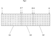
- Figure 3 shows a non-representative example of luminous intensity values for such a pattern. Since the original pattern has thousands of pixels, it will not be useful to represent all of them, but only a small representation has been chosen for the sake of clarity.
- This light pattern is divided into three portions: a first portion 11, a second portion 12 and a central portion 13.
- the first portion has a boundary column 3, which is adjacent to a first boundary column 7 of the central portion 13, and an end column 5, which is opposite to it.
- the second portion 12 has in turn a boundary column 4, which is adjacent to a second boundary column 8 of the central portion 13, and an end column 6, which is opposite to it.
- the central portion 13 has the first 7 and second 8 boundary columns.
- Figures 4a and 4b show the effect of two columns to the left bending light command, according to a particular embodiment of a method according to the invention.
- Figure 4a shows a first sub-step: the boundary columns are shifted to the left.
- the central portion remains the same, but shifted, while in the first and second portions, only the boundary columns and the end columns preserve their value.
- Figure 4b shows the interpolation of the rest of the values of the first and second portions. This is done by rows, adapting the values to the original ones, by "expanding” or “compressing” the intensity patterns following a linear interpolation.
- this row had the values 0-0-1-2-4-6-7-7-7-7-8-8-8-8-8-8-8-8-8-8-8-8-8-8-8-8-8-8-8-8-8-6-4-2-1-0-0-0-0-0.
- This row according to the division, will have a first portion 0-0-1-2-4-6-7-7-7-7-8-8, a second portion 8-6-4-2-1-0-0-0-0-0 and a central portion 8-8-8-8-8-8-8-8.
- the first portion will have the following pattern: 0-x-x-x-x-x-x-x-x-8, the second portion will be 8-x-x-x-x-x-x-x-x-x-x-0 and the central portion will be 8-8-8-8-8-8-8, but shifted two positions to the left, as shown in Figure 4a .
- the values x of the first portion will be calculated with respect to the data provided by the original first portion: at 8% the value is 0, at 17% the value is 1, at 25% the value is 2, at 33% the value is 4, at 42% the value is 6, at 50% the value is 7, at 58% the value is 7, at 67% the value is 7, at 75% the value is 7, at 83% the value is 8 and at 100% the value is 8.
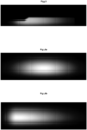
- Figure 5 shows an example of a light pattern which has undergone this shifting step. The central portion remains unchanged, but shifted to the left, while the left and right portions have been compressed and expanded.
- Figures 6a and 6b show a different example of a method according to the invention.
- Figure 6a shows a high beam light pattern, which is also divided into three portions.
- the central portion which comprises the maximum intensity values, is shifted but without any width variation.
- Figure 6b shows the effect of this modification.
- the first portion is compressed and the second portion is expanded according to the previously explained algorithm.
Landscapes
- Engineering & Computer Science (AREA)
- General Engineering & Computer Science (AREA)
- Mechanical Engineering (AREA)
- Lighting Device Outwards From Vehicle And Optical Signal (AREA)
Claims (9)
- Procédé destiné à contrôler un motif lumineux (1) fourni par un dispositif d'éclairage automobile (10) d'un véhicule automobile (100), dans lequel le motif lumineux (1) comprend un agencement matriciel de pixels lumineux, chaque pixel lumineux étant caractérisé par une valeur d'intensité lumineuse, le procédé comprenant les étapes de- réception d'une commande d'éclairage directionnel provenant du véhicule automobile (100) ;le procédé étant caractérisé par :- la division du motif lumineux (1) en au moins une première partie (11) et une deuxième partie (12), chaque partie (11, 12, 13) comprenant au moins une colonne limite (3, 4) qui est en contact avec la colonne limite d'une partie adjacente ;- la modification de la largeur de la première partie (11) et de la largeur de la deuxième partie (12) par décalage de la position des colonnes limites (3, 4) et interpolation des valeurs d'intensité lumineuse des pixels appartenant à la première et la deuxième partie (11, 12), dans lequel les colonnes limites (3, 4) qui étaient adjacentes avant le décalage restant adjacentes après le décalage ;- chacune des première et deuxième parties (11, 12) comprend une colonne d'extrémité (5, 6) qui se situe à l'opposé de la colonne limite correspondante (3, 4) et n'est pas décalée pendant l'étape de décalage ;- l'étape d'interpolation des valeurs d'intensité lumineuse est effectuée en tenant compte des valeurs d'intensité lumineuse de la largeur initiale entre la colonne d'extrémité correspondante (5, 6) et la colonne limite correspondante (3, 4) et en interpolant de nouvelles valeurs pour la nouvelle largeur de chaque partie ; et- dans lequel la commande d'éclairage directionnel comprend un nombre de positions à décaler et une direction de décalage, et l'étape de décalage de la position des colonnes limites est ensuite réalisée au moyen de ce nombre de positions à décaler dans la direction de décalage.
- Procédé selon la revendication 1 dans lequel l'interpolation des nouvelles valeurs est réalisée par une méthode bilinéaire ou une méthode de plus proches voisins.
- Procédé selon l'une quelconque des revendications précédentes, dans lequel le motif lumineux est divisé en deux parties et la division est effectuée pour que la moitié des colonnes lumineuses appartiennent à la première partie (11) et l'autre moitié à la deuxième partie (12).
- Procédé selon l'une quelconque des revendications 1 à 3, dans lequel le motif lumineux est divisé au moins en la première partie (11), la deuxième partie (12) et une partie centrale (13), dans lequel- la partie centrale (13) comprend une première colonne limite (7) adjacente à la colonne limite (3) de la première partie (11) et une deuxième colonne limite (8) adjacente à la colonne limite (4) de la deuxième partie (12) ; et- l'étape de modification de la largeur des première et deuxième parties (11, 12) implique également le décalage de la partie centrale (13) de la même manière que les colonnes limites (3, 4) des première et deuxième parties (11, 12), mais sans modification de la largeur ni des valeurs d'intensité lumineuse de la partie centrale (13).
- Procédé selon la revendication 4, dans lequel le motif lumineux est un motif de feu de croisement comprenant une zone coudée (14) et la partie centrale (13) contient la zone coudée (14).
- Procédé selon la revendication 4, dans lequel le motif lumineux est un motif de feu de route comprenant un pixel d'intensité lumineuse maximale (15) et la partie centrale (13) contient le pixel d'intensité lumineuse maximale (15).
- Procédé selon l'une quelconque des revendications 4 à 6, dans lequel la largeur de la partie centrale (13) est choisie de telle sorte que la première partie (11) et la partie droite (12) ont le même flux lumineux.
- Dispositif d'éclairage automobile (10) comprenant- un agencement matriciel de sources de lumière à semi-conducteurs (2), destiné à fournir un motif lumineux (1) ; et- une unité de commande (9) conçue pour effectuer les étapes d'un procédé selon l'une quelconque des revendications précédentes.
- Dispositif d'éclairage automobile selon la revendication 8, dans lequel l'agencement matriciel comprend au moins 2000 sources de lumière à semi-conducteurs (2).
Applications Claiming Priority (2)
| Application Number | Priority Date | Filing Date | Title |
|---|---|---|---|
| FR2002002A FR3107751B1 (fr) | 2020-02-28 | 2020-02-28 | Procédé de contrôle d'un motif lumineux et dispositif d'éclairage automobile |
| PCT/EP2021/054240 WO2021170509A1 (fr) | 2020-02-28 | 2021-02-19 | Procédé de commande d'un modèle d'éclairage et dispositif d'éclairage d'automobile |
Publications (2)
| Publication Number | Publication Date |
|---|---|
| EP4110651A1 EP4110651A1 (fr) | 2023-01-04 |
| EP4110651B1 true EP4110651B1 (fr) | 2025-04-02 |
Family
ID=72266354
Family Applications (1)
| Application Number | Title | Priority Date | Filing Date |
|---|---|---|---|
| EP21706939.2A Active EP4110651B1 (fr) | 2020-02-28 | 2021-02-19 | Procédé de commande d'un modèle d'éclairage et dispositif d'éclairage d'automobile |
Country Status (4)
| Country | Link |
|---|---|
| EP (1) | EP4110651B1 (fr) |
| JP (1) | JP7559075B2 (fr) |
| FR (1) | FR3107751B1 (fr) |
| WO (1) | WO2021170509A1 (fr) |
Families Citing this family (3)
| Publication number | Priority date | Publication date | Assignee | Title |
|---|---|---|---|---|
| FR3107943B1 (fr) * | 2020-03-09 | 2022-08-12 | Valeo Vision | Procédé de contrôle d'un motif lumineux et dispositif d'éclairage automobile |
| US12434622B2 (en) | 2021-03-29 | 2025-10-07 | Valeo Vision | Method for controlling a light pattern and automotive lighting device |
| FR3130938B1 (fr) * | 2021-12-17 | 2023-11-17 | Valeo Vision | Procédé de commande d’un éclairage directionnel et dispositif d’éclairage mettant en œuvre de ce procédé |
Family Cites Families (8)
| Publication number | Priority date | Publication date | Assignee | Title |
|---|---|---|---|---|
| JP2989364B2 (ja) * | 1992-03-12 | 1999-12-13 | シャープ株式会社 | 画像処理装置及び画像処理方法 |
| DE102011108384A1 (de) * | 2011-07-22 | 2013-01-24 | Audi Ag | Scheinwerfer für ein Kraftfahrzeug |
| JP5816031B2 (ja) | 2011-09-05 | 2015-11-17 | 株式会社小糸製作所 | 車両用前照灯装置 |
| JP2014004922A (ja) | 2012-06-25 | 2014-01-16 | Denso Corp | 車両用ヘッドランプ配光制御装置 |
| DE102013223711A1 (de) * | 2013-11-20 | 2015-05-21 | Osram Gmbh | Steuern eines wenigstens zwei Halbleiterlichtquellen aufweisenden Leuchtmittels |
| JP6282484B2 (ja) | 2014-02-21 | 2018-02-21 | スタンレー電気株式会社 | 発光装置 |
| CN107960069B (zh) | 2015-04-17 | 2024-02-02 | 株式会社小糸制作所 | 车辆用灯具 |
| AT518724B1 (de) * | 2016-06-13 | 2018-02-15 | Zkw Group Gmbh | Fahrzeugscheinwerfer und Verfahren zur Erzeugung einer Lichtverteilung |
-
2020
- 2020-02-28 FR FR2002002A patent/FR3107751B1/fr active Active
-
2021
- 2021-02-19 EP EP21706939.2A patent/EP4110651B1/fr active Active
- 2021-02-19 JP JP2022551394A patent/JP7559075B2/ja active Active
- 2021-02-19 WO PCT/EP2021/054240 patent/WO2021170509A1/fr not_active Ceased
Also Published As
| Publication number | Publication date |
|---|---|
| JP2023515964A (ja) | 2023-04-17 |
| FR3107751B1 (fr) | 2022-02-18 |
| JP7559075B2 (ja) | 2024-10-01 |
| FR3107751A1 (fr) | 2021-09-03 |
| EP4110651A1 (fr) | 2023-01-04 |
| WO2021170509A1 (fr) | 2021-09-02 |
Similar Documents
| Publication | Publication Date | Title |
|---|---|---|
| EP3670263B1 (fr) | Procédé de commande d'un motif lumineux et dispositif d'éclairage automobile | |
| EP4110651B1 (fr) | Procédé de commande d'un modèle d'éclairage et dispositif d'éclairage d'automobile | |
| US11435052B2 (en) | Method for correcting a light pattern and automotive lighting device | |
| EP3702663B1 (fr) | Procédé de correction d'un motif lumineux et dispositif d'éclairage automobile | |
| US12434622B2 (en) | Method for controlling a light pattern and automotive lighting device | |
| EP4117964B1 (fr) | Procédé de commande de motif lumineux et dispositif d'éclairage automobile | |
| EP3672369B1 (fr) | Procédé de commande d'un motif lumineux et dispositif d'éclairage automobile | |
| EP3730836A1 (fr) | Procédé de fourniture d'un motif lumineux, dispositif d'éclairage automobile et ensemble d'éclairage d'automobile | |
| US20240283950A1 (en) | Method for managing an image in an automotive lighting device and an automotive lighting device | |
| EP3702215B1 (fr) | Procédé de correction d'un motif lumineux et dispositif d'éclairage automobile | |
| US12479355B2 (en) | Method for controlling a light pattern and automotive lighting device | |
| US20240159371A1 (en) | Method for controlling a light pattern and automotive lighting device |
Legal Events
| Date | Code | Title | Description |
|---|---|---|---|
| STAA | Information on the status of an ep patent application or granted ep patent |
Free format text: STATUS: UNKNOWN |
|
| STAA | Information on the status of an ep patent application or granted ep patent |
Free format text: STATUS: THE INTERNATIONAL PUBLICATION HAS BEEN MADE |
|
| PUAI | Public reference made under article 153(3) epc to a published international application that has entered the european phase |
Free format text: ORIGINAL CODE: 0009012 |
|
| STAA | Information on the status of an ep patent application or granted ep patent |
Free format text: STATUS: REQUEST FOR EXAMINATION WAS MADE |
|
| 17P | Request for examination filed |
Effective date: 20220721 |
|
| AK | Designated contracting states |
Kind code of ref document: A1 Designated state(s): AL AT BE BG CH CY CZ DE DK EE ES FI FR GB GR HR HU IE IS IT LI LT LU LV MC MK MT NL NO PL PT RO RS SE SI SK SM TR |
|
| DAV | Request for validation of the european patent (deleted) | ||
| DAX | Request for extension of the european patent (deleted) | ||
| GRAP | Despatch of communication of intention to grant a patent |
Free format text: ORIGINAL CODE: EPIDOSNIGR1 |
|
| STAA | Information on the status of an ep patent application or granted ep patent |
Free format text: STATUS: GRANT OF PATENT IS INTENDED |
|
| INTG | Intention to grant announced |
Effective date: 20241031 |
|
| GRAS | Grant fee paid |
Free format text: ORIGINAL CODE: EPIDOSNIGR3 |
|
| GRAA | (expected) grant |
Free format text: ORIGINAL CODE: 0009210 |
|
| STAA | Information on the status of an ep patent application or granted ep patent |
Free format text: STATUS: THE PATENT HAS BEEN GRANTED |
|
| AK | Designated contracting states |
Kind code of ref document: B1 Designated state(s): AL AT BE BG CH CY CZ DE DK EE ES FI FR GB GR HR HU IE IS IT LI LT LU LV MC MK MT NL NO PL PT RO RS SE SI SK SM TR |
|
| REG | Reference to a national code |
Ref country code: GB Ref legal event code: FG4D |
|
| REG | Reference to a national code |
Ref country code: CH Ref legal event code: EP |
|
| REG | Reference to a national code |
Ref country code: DE Ref legal event code: R096 Ref document number: 602021028492 Country of ref document: DE |
|
| REG | Reference to a national code |
Ref country code: IE Ref legal event code: FG4D |
|
| REG | Reference to a national code |
Ref country code: NL Ref legal event code: MP Effective date: 20250402 |
|
| PG25 | Lapsed in a contracting state [announced via postgrant information from national office to epo] |
Ref country code: NL Free format text: LAPSE BECAUSE OF FAILURE TO SUBMIT A TRANSLATION OF THE DESCRIPTION OR TO PAY THE FEE WITHIN THE PRESCRIBED TIME-LIMIT Effective date: 20250402 |
|
| REG | Reference to a national code |
Ref country code: AT Ref legal event code: MK05 Ref document number: 1780993 Country of ref document: AT Kind code of ref document: T Effective date: 20250402 |
|
| PG25 | Lapsed in a contracting state [announced via postgrant information from national office to epo] |
Ref country code: FI Free format text: LAPSE BECAUSE OF FAILURE TO SUBMIT A TRANSLATION OF THE DESCRIPTION OR TO PAY THE FEE WITHIN THE PRESCRIBED TIME-LIMIT Effective date: 20250402 Ref country code: PT Free format text: LAPSE BECAUSE OF FAILURE TO SUBMIT A TRANSLATION OF THE DESCRIPTION OR TO PAY THE FEE WITHIN THE PRESCRIBED TIME-LIMIT Effective date: 20250804 Ref country code: ES Free format text: LAPSE BECAUSE OF FAILURE TO SUBMIT A TRANSLATION OF THE DESCRIPTION OR TO PAY THE FEE WITHIN THE PRESCRIBED TIME-LIMIT Effective date: 20250402 |
|
| REG | Reference to a national code |
Ref country code: LT Ref legal event code: MG9D |
|
| PG25 | Lapsed in a contracting state [announced via postgrant information from national office to epo] |
Ref country code: GR Free format text: LAPSE BECAUSE OF FAILURE TO SUBMIT A TRANSLATION OF THE DESCRIPTION OR TO PAY THE FEE WITHIN THE PRESCRIBED TIME-LIMIT Effective date: 20250703 Ref country code: NO Free format text: LAPSE BECAUSE OF FAILURE TO SUBMIT A TRANSLATION OF THE DESCRIPTION OR TO PAY THE FEE WITHIN THE PRESCRIBED TIME-LIMIT Effective date: 20250702 |
|
| PG25 | Lapsed in a contracting state [announced via postgrant information from national office to epo] |
Ref country code: PL Free format text: LAPSE BECAUSE OF FAILURE TO SUBMIT A TRANSLATION OF THE DESCRIPTION OR TO PAY THE FEE WITHIN THE PRESCRIBED TIME-LIMIT Effective date: 20250402 |
|
| PG25 | Lapsed in a contracting state [announced via postgrant information from national office to epo] |
Ref country code: BG Free format text: LAPSE BECAUSE OF FAILURE TO SUBMIT A TRANSLATION OF THE DESCRIPTION OR TO PAY THE FEE WITHIN THE PRESCRIBED TIME-LIMIT Effective date: 20250402 |
|
| PG25 | Lapsed in a contracting state [announced via postgrant information from national office to epo] |
Ref country code: HR Free format text: LAPSE BECAUSE OF FAILURE TO SUBMIT A TRANSLATION OF THE DESCRIPTION OR TO PAY THE FEE WITHIN THE PRESCRIBED TIME-LIMIT Effective date: 20250402 |
|
| PG25 | Lapsed in a contracting state [announced via postgrant information from national office to epo] |
Ref country code: AT Free format text: LAPSE BECAUSE OF FAILURE TO SUBMIT A TRANSLATION OF THE DESCRIPTION OR TO PAY THE FEE WITHIN THE PRESCRIBED TIME-LIMIT Effective date: 20250402 |
|
| PG25 | Lapsed in a contracting state [announced via postgrant information from national office to epo] |
Ref country code: RS Free format text: LAPSE BECAUSE OF FAILURE TO SUBMIT A TRANSLATION OF THE DESCRIPTION OR TO PAY THE FEE WITHIN THE PRESCRIBED TIME-LIMIT Effective date: 20250702 |
|
| PG25 | Lapsed in a contracting state [announced via postgrant information from national office to epo] |
Ref country code: IS Free format text: LAPSE BECAUSE OF FAILURE TO SUBMIT A TRANSLATION OF THE DESCRIPTION OR TO PAY THE FEE WITHIN THE PRESCRIBED TIME-LIMIT Effective date: 20250802 |
|
| PG25 | Lapsed in a contracting state [announced via postgrant information from national office to epo] |
Ref country code: LV Free format text: LAPSE BECAUSE OF FAILURE TO SUBMIT A TRANSLATION OF THE DESCRIPTION OR TO PAY THE FEE WITHIN THE PRESCRIBED TIME-LIMIT Effective date: 20250402 |
|
| REG | Reference to a national code |
Ref country code: DE Ref legal event code: R097 Ref document number: 602021028492 Country of ref document: DE |
|
| PG25 | Lapsed in a contracting state [announced via postgrant information from national office to epo] |
Ref country code: DK Free format text: LAPSE BECAUSE OF FAILURE TO SUBMIT A TRANSLATION OF THE DESCRIPTION OR TO PAY THE FEE WITHIN THE PRESCRIBED TIME-LIMIT Effective date: 20250402 Ref country code: SM Free format text: LAPSE BECAUSE OF FAILURE TO SUBMIT A TRANSLATION OF THE DESCRIPTION OR TO PAY THE FEE WITHIN THE PRESCRIBED TIME-LIMIT Effective date: 20250402 |
|
| PG25 | Lapsed in a contracting state [announced via postgrant information from national office to epo] |
Ref country code: CZ Free format text: LAPSE BECAUSE OF FAILURE TO SUBMIT A TRANSLATION OF THE DESCRIPTION OR TO PAY THE FEE WITHIN THE PRESCRIBED TIME-LIMIT Effective date: 20250402 |
|
| PG25 | Lapsed in a contracting state [announced via postgrant information from national office to epo] |
Ref country code: EE Free format text: LAPSE BECAUSE OF FAILURE TO SUBMIT A TRANSLATION OF THE DESCRIPTION OR TO PAY THE FEE WITHIN THE PRESCRIBED TIME-LIMIT Effective date: 20250402 |
|
| PG25 | Lapsed in a contracting state [announced via postgrant information from national office to epo] |
Ref country code: SK Free format text: LAPSE BECAUSE OF FAILURE TO SUBMIT A TRANSLATION OF THE DESCRIPTION OR TO PAY THE FEE WITHIN THE PRESCRIBED TIME-LIMIT Effective date: 20250402 |
|
| PG25 | Lapsed in a contracting state [announced via postgrant information from national office to epo] |
Ref country code: IT Free format text: LAPSE BECAUSE OF FAILURE TO SUBMIT A TRANSLATION OF THE DESCRIPTION OR TO PAY THE FEE WITHIN THE PRESCRIBED TIME-LIMIT Effective date: 20250402 |
|
| PLBE | No opposition filed within time limit |
Free format text: ORIGINAL CODE: 0009261 |
|
| STAA | Information on the status of an ep patent application or granted ep patent |
Free format text: STATUS: NO OPPOSITION FILED WITHIN TIME LIMIT |
|
| REG | Reference to a national code |
Ref country code: CH Ref legal event code: L10 Free format text: ST27 STATUS EVENT CODE: U-0-0-L10-L00 (AS PROVIDED BY THE NATIONAL OFFICE) Effective date: 20260211 |
|
| 26N | No opposition filed |
Effective date: 20260105 |
|
| PGFP | Annual fee paid to national office [announced via postgrant information from national office to epo] |
Ref country code: DE Payment date: 20260206 Year of fee payment: 6 |
|
| PGFP | Annual fee paid to national office [announced via postgrant information from national office to epo] |
Ref country code: FR Payment date: 20260227 Year of fee payment: 6 |