EP4110883B1 - Encres à nanoparticules colloïdales pour l'impression de couches actives dans un dispositif optoélectronique - Google Patents
Encres à nanoparticules colloïdales pour l'impression de couches actives dans un dispositif optoélectronique Download PDFInfo
- Publication number
- EP4110883B1 EP4110883B1 EP21708403.7A EP21708403A EP4110883B1 EP 4110883 B1 EP4110883 B1 EP 4110883B1 EP 21708403 A EP21708403 A EP 21708403A EP 4110883 B1 EP4110883 B1 EP 4110883B1
- Authority
- EP
- European Patent Office
- Prior art keywords
- ligands
- quantum dots
- nanoparticles
- capped
- shell
- Prior art date
- Legal status (The legal status is an assumption and is not a legal conclusion. Google has not performed a legal analysis and makes no representation as to the accuracy of the status listed.)
- Active
Links
Images



Classifications
-
- C—CHEMISTRY; METALLURGY
- C09—DYES; PAINTS; POLISHES; NATURAL RESINS; ADHESIVES; COMPOSITIONS NOT OTHERWISE PROVIDED FOR; APPLICATIONS OF MATERIALS NOT OTHERWISE PROVIDED FOR
- C09D—COATING COMPOSITIONS, e.g. PAINTS, VARNISHES OR LACQUERS; FILLING PASTES; CHEMICAL PAINT OR INK REMOVERS; INKS; CORRECTING FLUIDS; WOODSTAINS; PASTES OR SOLIDS FOR COLOURING OR PRINTING; USE OF MATERIALS THEREFOR
- C09D11/00—Inks
- C09D11/50—Sympathetic, colour changing or similar inks
-
- C—CHEMISTRY; METALLURGY
- C09—DYES; PAINTS; POLISHES; NATURAL RESINS; ADHESIVES; COMPOSITIONS NOT OTHERWISE PROVIDED FOR; APPLICATIONS OF MATERIALS NOT OTHERWISE PROVIDED FOR
- C09D—COATING COMPOSITIONS, e.g. PAINTS, VARNISHES OR LACQUERS; FILLING PASTES; CHEMICAL PAINT OR INK REMOVERS; INKS; CORRECTING FLUIDS; WOODSTAINS; PASTES OR SOLIDS FOR COLOURING OR PRINTING; USE OF MATERIALS THEREFOR
- C09D11/00—Inks
- C09D11/02—Printing inks
- C09D11/03—Printing inks characterised by features other than the chemical nature of the binder
- C09D11/033—Printing inks characterised by features other than the chemical nature of the binder characterised by the solvent
-
- C—CHEMISTRY; METALLURGY
- C09—DYES; PAINTS; POLISHES; NATURAL RESINS; ADHESIVES; COMPOSITIONS NOT OTHERWISE PROVIDED FOR; APPLICATIONS OF MATERIALS NOT OTHERWISE PROVIDED FOR
- C09D—COATING COMPOSITIONS, e.g. PAINTS, VARNISHES OR LACQUERS; FILLING PASTES; CHEMICAL PAINT OR INK REMOVERS; INKS; CORRECTING FLUIDS; WOODSTAINS; PASTES OR SOLIDS FOR COLOURING OR PRINTING; USE OF MATERIALS THEREFOR
- C09D11/00—Inks
- C09D11/02—Printing inks
- C09D11/03—Printing inks characterised by features other than the chemical nature of the binder
- C09D11/037—Printing inks characterised by features other than the chemical nature of the binder characterised by the pigment
-
- C—CHEMISTRY; METALLURGY
- C09—DYES; PAINTS; POLISHES; NATURAL RESINS; ADHESIVES; COMPOSITIONS NOT OTHERWISE PROVIDED FOR; APPLICATIONS OF MATERIALS NOT OTHERWISE PROVIDED FOR
- C09D—COATING COMPOSITIONS, e.g. PAINTS, VARNISHES OR LACQUERS; FILLING PASTES; CHEMICAL PAINT OR INK REMOVERS; INKS; CORRECTING FLUIDS; WOODSTAINS; PASTES OR SOLIDS FOR COLOURING OR PRINTING; USE OF MATERIALS THEREFOR
- C09D7/00—Features of coating compositions, not provided for in group C09D5/00; Processes for incorporating ingredients in coating compositions
- C09D7/80—Processes for incorporating ingredients
-
- C—CHEMISTRY; METALLURGY
- C09—DYES; PAINTS; POLISHES; NATURAL RESINS; ADHESIVES; COMPOSITIONS NOT OTHERWISE PROVIDED FOR; APPLICATIONS OF MATERIALS NOT OTHERWISE PROVIDED FOR
- C09K—MATERIALS FOR MISCELLANEOUS APPLICATIONS, NOT PROVIDED FOR ELSEWHERE
- C09K11/00—Luminescent materials, e.g. electroluminescent or chemiluminescent
- C09K11/02—Use of particular materials as binders, particle coatings or suspension media therefor
-
- C—CHEMISTRY; METALLURGY
- C09—DYES; PAINTS; POLISHES; NATURAL RESINS; ADHESIVES; COMPOSITIONS NOT OTHERWISE PROVIDED FOR; APPLICATIONS OF MATERIALS NOT OTHERWISE PROVIDED FOR
- C09K—MATERIALS FOR MISCELLANEOUS APPLICATIONS, NOT PROVIDED FOR ELSEWHERE
- C09K11/00—Luminescent materials, e.g. electroluminescent or chemiluminescent
- C09K11/02—Use of particular materials as binders, particle coatings or suspension media therefor
- C09K11/025—Use of particular materials as binders, particle coatings or suspension media therefor non-luminescent particle coatings or suspension media
-
- C—CHEMISTRY; METALLURGY
- C09—DYES; PAINTS; POLISHES; NATURAL RESINS; ADHESIVES; COMPOSITIONS NOT OTHERWISE PROVIDED FOR; APPLICATIONS OF MATERIALS NOT OTHERWISE PROVIDED FOR
- C09K—MATERIALS FOR MISCELLANEOUS APPLICATIONS, NOT PROVIDED FOR ELSEWHERE
- C09K11/00—Luminescent materials, e.g. electroluminescent or chemiluminescent
- C09K11/08—Luminescent materials, e.g. electroluminescent or chemiluminescent containing inorganic luminescent materials
- C09K11/58—Luminescent materials, e.g. electroluminescent or chemiluminescent containing inorganic luminescent materials containing copper, silver or gold
-
- C—CHEMISTRY; METALLURGY
- C09—DYES; PAINTS; POLISHES; NATURAL RESINS; ADHESIVES; COMPOSITIONS NOT OTHERWISE PROVIDED FOR; APPLICATIONS OF MATERIALS NOT OTHERWISE PROVIDED FOR
- C09K—MATERIALS FOR MISCELLANEOUS APPLICATIONS, NOT PROVIDED FOR ELSEWHERE
- C09K11/00—Luminescent materials, e.g. electroluminescent or chemiluminescent
- C09K11/08—Luminescent materials, e.g. electroluminescent or chemiluminescent containing inorganic luminescent materials
- C09K11/66—Luminescent materials, e.g. electroluminescent or chemiluminescent containing inorganic luminescent materials containing germanium, tin or lead
- C09K11/661—Chalcogenides
-
- C—CHEMISTRY; METALLURGY
- C09—DYES; PAINTS; POLISHES; NATURAL RESINS; ADHESIVES; COMPOSITIONS NOT OTHERWISE PROVIDED FOR; APPLICATIONS OF MATERIALS NOT OTHERWISE PROVIDED FOR
- C09K—MATERIALS FOR MISCELLANEOUS APPLICATIONS, NOT PROVIDED FOR ELSEWHERE
- C09K11/00—Luminescent materials, e.g. electroluminescent or chemiluminescent
- C09K11/08—Luminescent materials, e.g. electroluminescent or chemiluminescent containing inorganic luminescent materials
- C09K11/88—Luminescent materials, e.g. electroluminescent or chemiluminescent containing inorganic luminescent materials containing selenium, tellurium or unspecified chalcogen elements
- C09K11/881—Chalcogenides
-
- C—CHEMISTRY; METALLURGY
- C09—DYES; PAINTS; POLISHES; NATURAL RESINS; ADHESIVES; COMPOSITIONS NOT OTHERWISE PROVIDED FOR; APPLICATIONS OF MATERIALS NOT OTHERWISE PROVIDED FOR
- C09K—MATERIALS FOR MISCELLANEOUS APPLICATIONS, NOT PROVIDED FOR ELSEWHERE
- C09K11/00—Luminescent materials, e.g. electroluminescent or chemiluminescent
- C09K11/08—Luminescent materials, e.g. electroluminescent or chemiluminescent containing inorganic luminescent materials
- C09K11/88—Luminescent materials, e.g. electroluminescent or chemiluminescent containing inorganic luminescent materials containing selenium, tellurium or unspecified chalcogen elements
- C09K11/881—Chalcogenides
- C09K11/883—Chalcogenides with zinc or cadmium
-
- H—ELECTRICITY
- H10—SEMICONDUCTOR DEVICES; ELECTRIC SOLID-STATE DEVICES NOT OTHERWISE PROVIDED FOR
- H10K—ORGANIC ELECTRIC SOLID-STATE DEVICES
- H10K30/00—Organic devices sensitive to infrared radiation, light, electromagnetic radiation of shorter wavelength or corpuscular radiation
- H10K30/30—Organic devices sensitive to infrared radiation, light, electromagnetic radiation of shorter wavelength or corpuscular radiation comprising bulk heterojunctions, e.g. interpenetrating networks of donor and acceptor material domains
- H10K30/35—Organic devices sensitive to infrared radiation, light, electromagnetic radiation of shorter wavelength or corpuscular radiation comprising bulk heterojunctions, e.g. interpenetrating networks of donor and acceptor material domains comprising inorganic nanostructures, e.g. CdSe nanoparticles
-
- H—ELECTRICITY
- H10—SEMICONDUCTOR DEVICES; ELECTRIC SOLID-STATE DEVICES NOT OTHERWISE PROVIDED FOR
- H10K—ORGANIC ELECTRIC SOLID-STATE DEVICES
- H10K30/00—Organic devices sensitive to infrared radiation, light, electromagnetic radiation of shorter wavelength or corpuscular radiation
- H10K30/40—Organic devices sensitive to infrared radiation, light, electromagnetic radiation of shorter wavelength or corpuscular radiation comprising a p-i-n structure, e.g. having a perovskite absorber between p-type and n-type charge transport layers
-
- H—ELECTRICITY
- H10—SEMICONDUCTOR DEVICES; ELECTRIC SOLID-STATE DEVICES NOT OTHERWISE PROVIDED FOR
- H10K—ORGANIC ELECTRIC SOLID-STATE DEVICES
- H10K30/00—Organic devices sensitive to infrared radiation, light, electromagnetic radiation of shorter wavelength or corpuscular radiation
- H10K30/80—Constructional details
- H10K30/87—Light-trapping means
-
- H—ELECTRICITY
- H10—SEMICONDUCTOR DEVICES; ELECTRIC SOLID-STATE DEVICES NOT OTHERWISE PROVIDED FOR
- H10K—ORGANIC ELECTRIC SOLID-STATE DEVICES
- H10K39/00—Integrated devices, or assemblies of multiple devices, comprising at least one organic radiation-sensitive element covered by group H10K30/00
- H10K39/30—Devices controlled by radiation
- H10K39/32—Organic image sensors
-
- H—ELECTRICITY
- H10—SEMICONDUCTOR DEVICES; ELECTRIC SOLID-STATE DEVICES NOT OTHERWISE PROVIDED FOR
- H10K—ORGANIC ELECTRIC SOLID-STATE DEVICES
- H10K71/00—Manufacture or treatment specially adapted for the organic devices covered by this subclass
- H10K71/10—Deposition of organic active material
- H10K71/12—Deposition of organic active material using liquid deposition, e.g. spin coating
- H10K71/13—Deposition of organic active material using liquid deposition, e.g. spin coating using printing techniques, e.g. ink-jet printing or screen printing
- H10K71/135—Deposition of organic active material using liquid deposition, e.g. spin coating using printing techniques, e.g. ink-jet printing or screen printing using ink-jet printing
-
- H—ELECTRICITY
- H10—SEMICONDUCTOR DEVICES; ELECTRIC SOLID-STATE DEVICES NOT OTHERWISE PROVIDED FOR
- H10K—ORGANIC ELECTRIC SOLID-STATE DEVICES
- H10K85/00—Organic materials used in the body or electrodes of devices covered by this subclass
- H10K85/30—Coordination compounds
-
- H—ELECTRICITY
- H10—SEMICONDUCTOR DEVICES; ELECTRIC SOLID-STATE DEVICES NOT OTHERWISE PROVIDED FOR
- H10K—ORGANIC ELECTRIC SOLID-STATE DEVICES
- H10K85/00—Organic materials used in the body or electrodes of devices covered by this subclass
- H10K85/30—Coordination compounds
- H10K85/371—Metal complexes comprising a group IB metal element, e.g. comprising copper, gold or silver
-
- H—ELECTRICITY
- H10—SEMICONDUCTOR DEVICES; ELECTRIC SOLID-STATE DEVICES NOT OTHERWISE PROVIDED FOR
- H10K—ORGANIC ELECTRIC SOLID-STATE DEVICES
- H10K85/00—Organic materials used in the body or electrodes of devices covered by this subclass
- H10K85/30—Coordination compounds
- H10K85/381—Metal complexes comprising a group IIB metal element, e.g. comprising cadmium, mercury or zinc
-
- B—PERFORMING OPERATIONS; TRANSPORTING
- B82—NANOTECHNOLOGY
- B82Y—SPECIFIC USES OR APPLICATIONS OF NANOSTRUCTURES; MEASUREMENT OR ANALYSIS OF NANOSTRUCTURES; MANUFACTURE OR TREATMENT OF NANOSTRUCTURES
- B82Y20/00—Nanooptics, e.g. quantum optics or photonic crystals
-
- B—PERFORMING OPERATIONS; TRANSPORTING
- B82—NANOTECHNOLOGY
- B82Y—SPECIFIC USES OR APPLICATIONS OF NANOSTRUCTURES; MEASUREMENT OR ANALYSIS OF NANOSTRUCTURES; MANUFACTURE OR TREATMENT OF NANOSTRUCTURES
- B82Y40/00—Manufacture or treatment of nanostructures
Definitions
- the present disclosure relates to (manufacturing of) inks with colloidal nanoparticles, such as quantum dots, in particular inks and compositions suitable in the deposition, e.g., printing, of active layers, e.g. for use in optoelectronic devices.
- colloidal nanoparticles such as quantum dots
- active layers e.g. for use in optoelectronic devices.
- colloidal suspensions of nanoparticles, nanocrystals and/or quantum dots are used in a broad range of applications including for fabrication of electronic devices such as field-effect transistors (FETs), solar cells, light emitting FETs, light emitting diodes, photodetectors for visible, IR, X-ray or gamma irradiation, phototransistors, thermoelectrics, bolometers and others.
- electronic devices such as field-effect transistors (FETs), solar cells, light emitting FETs, light emitting diodes, photodetectors for visible, IR, X-ray or gamma irradiation, phototransistors, thermoelectrics, bolometers and others.
- water-based dispersions of quantum dots can be used as a platform for bioapplications.
- Linkers, e.g. ligands on the quantum dot surface allow manufacturing of conjugates of various biological molecules, e.g., using quantum dots as fluorescent markers.
- Colloidal quantum dots typically comprise nanocrystals of inorganic material that have discrete energy levels due to quantum confinement of electrons within the volume of the nanoparticles.
- Quantum dots can be synthesized in a form of a colloidal solution of quantum dots, and after purification can be dispersed in a nonpolar organic solvent such as hexane.
- a nonpolar organic solvent such as hexane.
- individual quantum dots are capped with long aliphatic molecules, called ligands.
- these ligands may include oleic acid (OA) or oleylamine (OAm), which bind to the surface of quantum dots via carboxyl or amine group.
- the aliphatic tails of the ligands ensure the colloidal stability of such quantum dot solutions, creating repulsive forces between quantum dots counterbalancing the attractive component of van der Waals forces acting on a particle approaching another particle. This way of stabilization is referred to as steric stabilization of colloids.
- quantum dot solutions are generally less suitable for direct application.
- the nonpolar solvent may be incompatible with an envisioned biological application.
- a film deposited from such quantum dot solution typically shows very poor electronic performance.
- One approach to overcome this problem comprises use of a phase-transfer ligand exchange, which is a method wherein the ligands on the surface of the quantum dots are substituted by different entities, e.g., ligands. Typically, this process is performed in solution.
- US6251303B1 discloses a method for manufacturing of water-soluble fluorescent nanocrystals.
- fluorescent nanocrystals bearing a cap of nonpolar ligands are separated from suspension.
- the nonpolar ligands are exchanged for a different precursor ligand by exposing the separated fluorescent nanocrystals to a new solution comprising a 30-fold excess of said precursor ligands at elevated temperatures.
- the nanocrystals can be rendered water soluble in separate step by protonating the precursor ligands.
- Hak Soo Choi et al disclose a ligand exchange process that can provide CdSe/ZnS core-shell quantum dots that are capped with cysteamine for bio applications.
- the process uses a water/chloroform-based ligand exchange process in which the water phase is provided with a phosphate-buffered saline buffer to dissolve the quantum dots.
- Formed quantum dot suspensions thus comprise a lot of salt and/or a large excess of unbound ligand rendering them less suitable for fabrication of electronic devices.
- noisy T et al disclose a method of manufacturing cysteamine CdS quantum dots decorated with Fe 3+ as a fluorescence sensor for the detection of pyrophosphate.
- the CdS quantum dots were directly synthesized with cysteamine ligands using a one-pot synthesis. During synthesis the dots do not benefit from the stabilizing effect of long aliphatic ligands. Formed dots were found to be of lower quality and thus less suitable for electronic grade quantum dot inks.
- US2007174939A1 discloses methods of making quantum dot films for use in optical and optoelectronic devices.
- the method comprises pre-fabricate quantum dots and ligand exchange.
- the ligand exchange includes precipitating the as-synthesized quantum dots from their original solution and dispersing the separated particles in a liquid comprising the exchange ligands. Accordingly, the method of US2007174939A1 shares one or more of the disadvantages described in relation to US6251303B1 .
- Database WPIWeek 201985Thomson Scientific, London, GB;AN 2019-88184Q-& WO 2019/203240 A1 (Shoei Chem Inc) 24 October 2019 (2019-10-24) describes a nanoparticle manufacturing system comprising inflow systems, rotor, stator and collection system; and manufacture of nanoparticle ink formulation, which involves mixing and processing solutions in the shear flow reactor to form a product mixture containing mixed nanoparticle ink.
- the method of manufacturing of an ink composition comprising the biphasic ligand exchange process according to the present invention aims to mitigate one or more of the disadvantages described above and/or offering one or more further advantages in the manufacturing of electronic devices from the ink compositions.
- a first phase liquid comprises a nonpolar solvent with a suspension (a colloidal suspension) of nanoparticles dispersed in the nonpolar solvent.
- the nanoparticles e.g. quantum dots
- a second phase liquid comprises a polar solvent with second ligands dissolved therein.
- the second ligand has a molecular architecture including at least one surface binding head group that has an affinity for binding to a surface site of said nanoparticle.
- the architecture includes at least an ionically charged tail group and a counter ion associated therewith.
- a biphasic ligand exchange process is used wherein the second ligand displace the first ligands that are bound to the nanoparticles. Thereby, the first ligands are released to the first phase liquid.
- the biphasic ligand exchange process involves contacting the first and second phase liquid. This forms a dispersion of the nanoparticles, e.g., the quantum dots, that are capped with a shell of the second ligands in the second phase liquid.
- the nanoparticles that are capped with a shell of the second ligands can be separated from the second phase liquid.
- the separated nanoparticles (quantum dots) that are capped with a shell of the second ligands can be (re)dispersed in a printable liquid medium.
- an ink can be formed of which the printing properties may be further tuned, e.g. by addition of other or further additives.
- a dry composition comprising the nanoparticles, preferably quantum dots, that are capped with a shell of second ligand obtainable by any of the methods as described herein, wherein the method further comprises drying the separated quantum dots that are capped with a shell of the second ligands.
- an ink composition comprising nanoparticles that are capped with a shell of polar organic ligands according to claim 8.
- the ink composition comprising a colloidal suspension of quantum dots in a polar printable liquid medium, wherein the quantum dots are capped with a shell of second ligands and wherein the second ligand has a molecular architecture including: at least one surface binding head group that has an affinity for binding to a surface site of said quantum dot; and an ionically charged tail group and a counter ion associated therewith.
- aspects of the present disclosure also relate to a method of manufacturing an imaging device comprising a stack of photoactive layers including at least a p-type photoactive layer and/or an n-type photoactive layer.
- the method comprising depositing one or more layers of the ink composition comprising a p-type dopant as described herein or of the ink obtainable by the method as described herein; and depositing one or more layers of the ink composition comprising a n-type dopant as described herein or of the ink obtainable by the method as described herein, to from a stack of photoactive layers including at least a p-type photoactive layer and/or an n-type photoactive layer, and wherein the photoactive layers are amorphous, comprising a disordered structure of nanoparticles resulting from deposition of the respective ink composition.
- ink, and intermediary products offer certain advantages. These include provision of a facile and/or versatile ligand exchange process allowing manufacturing of quantum dots that are capped with a broad variety of second ligands.
- nanoparticle degradation can be mitigated as manufacturing of the ink can be performed at room temperature and/or without the presence of harsh conditions, e.g. without exposure to high concentration of strong acids or bases.
- separating the nanoparticle that are capped with a shell of the second ligands from the second phase comprising a first polar solvent and re-dispersing the quantum dots in a different polar liquid, e.g. a liquid printing medium allows optimizing properties of the ink, e.g. the type of solvent comprised therein, independent from selection criteria governed by the ligand exchange process.
- optical and electronic properties of obtained nanoparticle can remain stable, e.g., over prolonged periods of time, as dry compositions of obtained nanoparticle that are capped with a shell of the second ligands can be stored without losing essential functionality.
- Advantageously stored compositions can be (re)dispersed in a suitable printable liquid medium before usage.
- the two phase ligand exchange process according to the present invention can be understood to yield capped nanoparticles that were found to be particularly beneficial for use in the manufacturing of a photoactive layer of an optoelectronic device by providing a combination of advantageous properties.
- Advantages include that the particles manufactured according to the disclosed process were found to be essentially free of hydrophobic ligand moieties and/or oily or waxy impurities that were associated with the nanoparticles as synthesized.
- the biphasic ligand process according to the present invention can be understood as a purification or cleaning procedure allowing to essentially replace the an initial hydrophobic capping layer, including possible contaminants, by a replacement capping layer of different functional moieties as disclosed herein.
- the replacement capping layer offers improved optoelectronic properties.
- the replacement capping layer was found to effectively stabilize the nanoparticles in dry form while allowing (re)solubilization of dried particles in polar solvents including ink compositions for use in the manufacturing of a photoactive layer for optoelectronic devices.
- properties of compounds of mixtures e.g., solubility, referred to herein are specified at room temperature and standard pressure, e.g. twenty degrees Celsius and one atmosphere.
- Nanoparticles comprise a dense core of inorganic material that has at least one dimension lower than one thousand nanometer, e.g. in a range between one, or ten, Angstrom and one hundred nm, preferably in a range between about one nanometer and about fifty nanometer, e.g. a about two to ten nanometer, e.g. three nanometer.
- Colloidal nanocrystals (NCs) of semiconducting materials with distinctive electronic properties determined by their size are often referred as quantum dots (QDs) or colloidal quantum dots (QCDs) due to quantum confinement effect.
- QDs quantum dots
- QDs colloidal quantum dots
- Advantages of QDs include: size-tunable band gap, high light absorption coefficient and solution processability.
- Quantum dots synthesized from solution are typically referred to as colloidal quantum dots or colloidal nanocrystals.
- colloidal quantum dots are generally capped with long aliphatic ligands (such as oleic acid or oleylamine), ensuring homogeneous growth of the nanoparticles and the colloidal stability of the solution.
- long aliphatic ligands such as oleic acid or oleylamine
- other ligands including and not limited to various phosphines and phosphine oxides (such as trioctylphosphine and trioctylphosphine oxide) can be employed.
- Quantum dots can be manufactured using other methods including plasma synthesis. Quantum dots synthesized by plasma are usually in the form of powder, for which surface modification, e.g. passivation with aliphatic ligands may be carried out.
- Nanoparticles have been reported for a broad range of compositions. Examples include mono-elemental nanoparticles (Ag, Au, Ni, Ru, Rh, Pd, Pt, Sn, Si, Ge, Ga, In, Fe, Mn, Co, Cu, Be, C, B, Al, Sb, Li, Na, K, Y, lanthanide, etc.), carbonaceous-based nanoparticles, metal and/or lanthanide oxide nanoparticles (Fe 2 O 3 , Fe 3 O 4 , MnO, Mn 2 O 3 , Mn 3 O 4 , MgO, CaO, BaO, ZnO, TiO 2 , NiO, Ni 2 O 3 , In 2 O 3 , Ga 2 O 3 , Be 2 O 3 , Y 2 O 3 , SiO 2 , V 2 O 3 , V 2 O 5 , CeO 2 , Al 2 O 3 , GeO 2 , ZrO 2 , HfO 2 , CuO, Cu 2 O, Sn
- particles suitable for use with the invention are not to be construed as to be limited to the listed exemplary compositions.
- Particles comprising a mixture or combination of the abovementioned materials can be equally used to advantage, including for example, core/shell structures or segmented particles, and also alloys, such as AgInS2, and/or doped particles.
- the shape of the nanoparticles can be understood to include, but not limited to, spheres, cylinders, discs, toroids, wires, rods, needles, cubes, cuboctahedrons, parallelepipeds (bar), tetrahedral, octahedral, icosahedra, dodecahedra, prisms, nanoplates, nanofoil, nanotubes, of various shape (quadratic, triangular, rectangular, hexagonal etc), stars, tetrapods, hyperbranched and branched.
- nanoparticles can be provided in a core/shell configuration or core/shell/shell structures having layers of different composition, wherein the interface between layers of different composition may be a sharp interface or gradual interface.
- the nanoparticles can be hollowed or porous or could combine two or more shapes of one or more materials.
- the biphasic ligand exchange process as described herein can be used to advantage for a broad variety of nanoparticles, including nanocrystals and quantum dots.
- a process or step as described herein below that is explained relation to a specific type of nanoparticle, e.g. a quantum dots, is not to be inferred as to be limited to that specific type of nanoparticle. Rather, a selection of nanoparticles type can be understood to be governed by a target application, e.g. based on a requirement of an active component in an optoelectronic device.
- non polar solvents used herein may be understood to include, linear-, branched-, cyclic-, or halogenated alkanes, alkenes, and alkynes, as well as aromatic compounds.
- Nonpolar solvents include but are not limited to pentanes, like n-pentane and 2,2,4-trimethylpentane, hexanes, like n-hexane, heptanes, octanes, nonane, decane , dodecane, hexadecane, 1-octadecene, petroleum ether, poly( ⁇ -olefin)s and oligo( ⁇ -olefin)s, squalane, cyclopentane, cyclohexane, benzene, toluene, ethylbenzene, xylenes, like p-xylene, trimethylbenzenes, cumene, chlorobenzene, dichloro
- polar solvents used herein may be understood to include, but not limited to, methanol, ethanol, propanol, isopropanol, butanol, ethylene glycol, glycerol, 1,3-butanediol, ammonia, hydrazine, acetone, acetonitrile, benzonitrile, formamide, N-methylformamide, dimethylformamide, dimethylacetamide, dimethylsulfoxide, hexamethylphosphoramide, propylene carbonate, N-methyl-2-pyrrolidone, nitromethane, methylamine, dimethylamine, ethylamine, propylamine, butylamine, triethylamine, trimethylamine, ethanolamine, methoxyethanol, ethylenediamine, dimethylethylenediamine, tetramethylethylenediamine, tetrakis(dimethylamino)ethylene, pyridine, 2,6-difluoropyridine, water
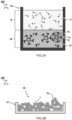
- FIGs 1-2 schematically illustrate manufacturing of an ink composition 100 at various stages.
- FIG 1A schematically illustrates a biphasic ligand setup.
- the setup as shown is formed by a container 50, e.g. beaker. Of course also other setups can be used.
- the container has at least a transparent side wall portion such that progress may be followed visually.
- the first phase liquid 10 comprises or is essentially formed of a nonpolar solvent 11 or a mixture of nonpolar solvents. Dispersed in the solvent is a suspension (a colloidal suspension) of quantum dots 1.
- the quantum dots 1 are capped with a shell 2s of first ligands 2.
- the ligands comprise a surface binding head group 2h that binds to a surface site on the quantum dot.
- the ligands further comprise a nonpolar alkyl or alkenyl tail 2t for at least initially keeping the quantum dots 1 in a colloidal suspension in the nonpolar solvent 11.
- the shell 2s of first ligands (indicated by a dashed circle) is sometimes referred to as a corona, may be understood to included a volume around the quantum dot that is occupied by the second ligands.
- Quantum dots synthesized from solution are typically referred to as colloidal quantum dots or colloidal nanocrystals.
- colloidal quantum dots are generally capped with long aliphatic ligands (such as oleic acid or oleylamine) which are believed to ensure homogeneous growth of the nanoparticles and the colloidal stability of the solution.
- Quantum dots can be manufactured using other methods including plasma synthesis.
- the method includes a step of capping the quantum dots with a shell 2s of first ligands 2.
- the type and/or composition of the quantum dots can depend on its desired application.
- the method as disclosed herein is not to be construed to be limited to a certain type and/or composition of quantum dots per se.
- the disclosed method of forming an ink was found to work for a broad range of quantum dots that are capped with a shell of aliphatic ligands which are sufficiently labile to be replaced by second ligands.
- Suitable quantum dots include but are not limited to Au, PbS, PbSe, and CdSe quantum dots as well as multi-layer dots comprising such outer coating.
- the second phase liquid comprises or is essentially formed of a polar solvent 21 or mixture of polar solvents in which an amount of second ligand 3 is dissolved.
- a third solvent can be added to the biphasic mixture.
- the third solvent being miscible with the liquids that make up the first and second phase liquids. Addition of a co-solvent was found to promote, speed up, ligand exchange. Miscibility of the third solvent being defined as forming a single phase fluid with an equal volume of the nonpolar solvent, respectively with an equal volume of the first polar solvent.
- the second ligand has a multi-block molecular architecture that includes at least one surface binding head group 3h that has an affinity for binding to a surface site of the quantum dots 1, and an ionically charged tail group 3t and a counter ion 3c associated therewith.
- the second ligand comprises an organic spacer 3s separating the head group and the tail group. Details regarding the second ligand will be described later. It was found that further additives, such as pH-buffers, are not required to drive the ligand exchange reaction to completion.
- the second phase liquid is preferably free of such additives, i.e. consist of a solution of one or more second ligands in a polar solvent or mixture of solvents.
- the first and second phase liquid may be understood to be mutually essentially immiscible.
- Mutually essentially immiscible liquids e.g. the first and second phase liquid
- Providing mutually essentially immiscible phases can advantageously be separated form each other relative ease, e.g. by decanting or pouring.
- the exact composition of the first and second phase liquid can depend on the type of quantum dot and/or of the type of the first ligands capping said quantum dot.
- the first phase liquid can disperse the quantum dots that are capped with a shell of first ligands in a concentration of at least 10 mg/mL.
- the first phase liquid can preferably dissolve the first ligands in a concentration of at least 10 mM.
- the second phase liquid is a poor dispersing medium for the first ligands and for the quantum dots that are capped with a shell of first ligands.
- the solubility of the first ligands in the second phase liquid is below 0.1 mM.
- the solubility of the quantum dots that are capped with the first ligands in the second phase liquid is below 0.1 mg/mL, or lower, e.g. below 0.01 mg/mL, preferably practicable negligible.
- the second phase liquid is a good solvent for the second ligands. The higher the solubility of the second ligands the better dispersing medium the second phase liquid can be for quantum dots that are capped with a shell of the second ligands.
- the solubility of the second ligands is preferably at least 10 mM, preferably higher e.g. at least 20 mM or more, e.g. at least 30 mM.
- the first and second phase liquid may each individually comprise a single solvent or a mixture of solvents.
- the first phase liquid comprises a nonpolar solvent or mixture of nonpolar solvents.
- a nonpolar solvent sometimes referred to as an apolar solvent, may be understood to include solvents having a low net dipole moment.
- the nonpolar solvent has a dipole moment below 1.5 D (Debye units/ 1 ⁇ 10 -18 statcoulomb-centimeters). The lower the dipole moment of a solvent the lower the solubility of polar compounds in that solvent. More preferably, the nonpolar solvent has a dipole moment below 1.0 D or lower, e.g., below 0.5 D, e.g., in a range between 0.35 and 0 D.
- Choice of the first phase liquid, including the one or more polar solvents may be limited by an availability, e.g. a commercial availability, of quantum dots that are capped with a shell of first ligands.
- quantum dots that are capped with a shell of ligands comprising a surface binding head group and an alkyl or alkenyl having a number of carbon atoms n in a range between 12 and 20, e.g. oleic acid, oleylamine, ocdadecylamine and hexdecanoic acid)
- first phase liquids comprising or essentially consisting of one or more aliphatic solvents, including but not limited to hexanes and octane to be suitable.
- the polar solvent 21, may be understood to include solvents having a high net dipole moment.
- the polar solvent has a dipole moment above 1.5 D (Debye units/ 1 ⁇ 10 -18 statcoulomb-centimeters). The higher the dipole moment of a solvent the lower the solubility of nonpolar compounds in the solvent. More preferably, the nonpolar solvent has a dipole moment above 1.6 D or higher, e.g., above 2, e.g., in a range between 1.5 and 5.
- the difference in dipole moment and/or logP were found to provide further selection criteria.
- the difference in dipole moment between the first and second phase liquids was found to be preferably at least 0.5D.
- the difference in dipole moment between the first and second phase liquids is higher, e.g. at least 0.7 D or at least 1.0 D or more.
- Suitable polar solvents were typically found to have a negative logP value. Solvents with a negative logP value were generally found to be good solvents for the second ligands.
- the polar solvents has a logP below about negative 0.2. Solvents with a lower logP value were generally found to be less miscible in the first phase liquid and/or less good solvents for the first ligands.
- a two phase system is formed in which the respective liquids are separated across a common interface.
- a biphasic ligand exchange process can start wherein the second ligand displaces the first ligands that are bound to the quantum dots 1.
- FIG 1B schematically illustrates the biphasic ligand exchange process at an initial stage, e.g., shortly after contacting the liquids.
- Contacting typically includes adding the first and second phase liquids in a common container 50, e.g., a vial.
- the second phase liquid can be added to a container provided with an amount of the first phase liquid, or vice versa, i.e. adding the first liquid to a container comprising the second phase liquid.
- the second ligands or a part thereof may be added in a separate step, e.g., to a common container comprising the first and second phase liquids, e.g. in response to an observed or determined progress of the ligand exchange reaction.
- the first phase liquid 10 and second phase liquid 20 respectively including the nonpolar solvent 11 with the quantum dots 1 that are capped with a shell of first ligands 2, and the polar solvent 21 with the second ligand 3 interact over a common interface 19 (indicated in the figure with a dash-dot line).
- a common interface 19 indicated in the figure with a dash-dot line.
- the method preferably includes agitating the contacted first and second phase liquids, e.g. by shaking or stirring.
- first ligands 2 At the interface ligands (first ligands 2), initially bound to the surface of the quantum dots 1, are displaced by the second ligand 3. It is believed that the exchange reaction proceeds on account of the higher surface affinity of the head group 3h of the second ligand 3 towards the quantum dot compared to the affinity of the head group 2h of the first ligand 2. Displaced first ligand moieties are thereby released ligands to the first phase liquid 10.
- FIG 2A schematically illustrates a later stage of the biphasic ligand exchange process, i.e. during contacting the first 10 and second phase liquid 20.
- the exchange reaction can proceed to completion forming a dispersion of quantum dots 1 that are capped with a shell 3s of the second ligands 3 in the second phase liquid.
- the second phase liquid 20 may comprise a remainder (an excess) of ligands 3' after essentially all quantum dots 1 are capped with a shell 3s of the second ligands 3.
- the method comprises washing the second phase liquid 20 which contains quantum dots capped with a shell of the second ligands 3s with one or more portions of a solvent for the first ligand. Washing the quantum dots that are capped with a shell of the second ligands 3s in second phase liquid 20 with one or more portions of a solvent for the first ligand can reduce an amount of free (unbound) first ligand in the product, which can be dissolved in liquid 20 in a minor concentration. Contaminations, e.g. an excess of ligand, can form a non-conductive or interfering domains in printed layers of quantum dots. As such the excess ligands which can negatively impart properties, e.g., electrical conductance, of a sensing material layer.
- the dispersion of quantum dots 1 that are capped with a shell 3s of the second ligands 3 in the second phase liquid may be considered to be an ink 100 composition.
- the quantum dots 1 that are capped with a shell 3s of the second ligands 3 are preferably separated from the second phase liquid.
- the quantum dots 1 that are capped with a shell 3s of the second ligands 3 are preferably essentially free of contaminants, i.e. highly pure. Contaminants, e.g. unbound ligands, salts, grease and/or wax, were found to negatively affect photoelectrical properties of the particles, e.g. of a film formed from an ink comprising said particles and impurities. Mitigating introduction and/or reducing a level of impurities is preferred over subsequent removal or purification procedures, as such subsequent cleaning or purification procedures, e.g. washing steps, can impact particle stability. Purity can be understood to be defined as the mass fraction of the quantum dots with a shell of the second ligands in the final dry powder. Preferably, the purity of the quantum dots is 90%, more preferably above 99%.
- FIG 2B schematically illustrates a container 51 containing isolated quantum dots 1 that are capped with a shell of second ligands 3s.
- the isolated quantum dots 1 that are capped with a shell of second ligands 3s can be obtained by separating the quantum dots that are capped with a shell of the second ligands are separated from the second phase liquid. Separating the quantum dots that are capped with a shell of the second ligands from the second phase liquid including possible excess unbound second ligands dissolved therein, is preferably preceded by separating said second phase from the first phase liquid, e.g., by decanting, pouring or suctioning.
- Separation of the quantum dots that are capped with a shell of the second ligands from the second phase liquid may be attained by any suitable method known in the field.
- separation may be attained by centrifuging, to sediment the second ligand capped quantum dots from the polar phase. Centrifuging was found to be a reliable and fast method to separate particles from suspension forming a pellet of quantum dots 1 that are capped with a shell 3s of the second ligands 3.
- the separates quantum dots e.g. in the form of a pellet, may be retrieved and stored easily.
- Quantum dots that are capped with a shell of the polar ligands when provided in a dry form e.g.
- separating comprises adding of an anti-solvent to precipitate the quantum dots.
- the supernatant comprising a possible excess of free unbound second ligands can be discarded.
- separation further includes a drying step, e.g. a vacuum drying step, to evaporate remaining solvent.
- the second ligands comprise at least one surface binding head group that has an affinity for binding to a surface site of the quantum dots; and an ionically charged tail group and a counter ion associated therewith as defined in claim 1.
- the head group of the second ligand binds to the surface of the quantum dots, i.e. surface atoms of the quantum dots, via a hetero atom.
- the nature of the quantum dots i.e. the type of binding sites available on an outer surface of the quantum dot, can determine selection of the type of surface binding head group of the second ligands.
- the surface binding head group comprises a thiol head group.
- thiols, thioesters and disulfides are known to readily bind to a broad variety of surfaces by formation of a covalent metal-sulfur bond. Suitable surfaces including metal surfaces like Au and Ag, and semi-conductor surfaces including but not limited to chalcogenic materials such as CdS, CdSe, PbS, PbSe. Accordingly, for quantum dots of which the outer surface comprises such materials, the surface binding head of the second ligands is thio-based.
- the charged tail group of the second ligand provides the quantum dots with a shell that includes electrically charged groups.
- the charge functionality can be provided by a permanent ionic charge or a functional group which can become charged, e.g. a conjugate acid of a weak base or a conjugate base of a weak acid.
- Suitable charged tail groups group include, but are not limited to, carboxylates, sulphonic acids, phosphites, phosphonates, hydroxyls, sulphonates, amines, quaternary ammonium salts, carbocations, carboanions, etc.
- the charged tail group includes acid adducts of a weak organic base, e.g., a hydrochloride adduct of a primary-, secondary or ternary amine.
- the charged tail group includes a water soluble salt of an organic acid, e.g. sodium carboxylates or sulfonates.
- the organic spacer separating the head group and the tail group can in principle be formed by any organic group that links, covalently links, the head group to the tail group as defined in claim 1.
- the nature of the linker may play a more or less important role.
- the quantum dots are comprised in a dense functional layer, e.g., an electrically conductive sensing layer
- the size or length of the length of the spacer influences the interdistance between adjacent quantum dots within a dense layer of quantum dots.
- the organic spacer is a short spacer. The shorter the spacer the closer the quantum dots, i.e.
- the spacer is an aliphatic spacer, e.g. -C n H 2n -, wherein the number of carbon atoms (n) equals 1, 2 or 3.
- FIG 3A schematically depicts Markush formulas representing classes of second ligands 3 as described herein.
- the class of compounds depicted in FIG 3A comprises a thiol head group (SH) for binding the second ligand to the surface of the quantum dots.
- the charged tail group (Y) represents: an acid adduct of a weak organic base, e.g., a hydrochloride adduct of a primary-, secondary or tertiary amine; or a water soluble salt of an organic acid, e.g. sodium carboxylates or sulfonates.
- the spacer is an alkyl spacer having a total number of carbon atoms n in a range from 1 to 3.
- the charged tail group is formed by an acid adduct of an organic amine, e.g. as shown in FIG 3C wherein R1 and R2 each individually represent an H or a methyl group, and wherein X represents a halide, preferably Cl.
- the charged tail group is formed by a metal salt of a weak organic acid, e.g. as shown in FIG 3B , wherein M represents an alkali metal, preferably Na.
- the second ligands can be formed in situ, e.g. as a product of a reaction in the second phase liquid 20. Generating the second ligand (3) in situ, e.g.
- Suitable reactions include formation of the acid adduct of a weak organic base and formation of a metal salt of a weak organic acids, respectively by reaction of a strong acid or strong base with the corresponding weak organic base or weak organic acid.
- Suitable second ligand 3 moieties may further be dissociation products of a corresponding disulfide precursor moiety.
- Exemplary second ligands 3 as described herein include cysteamine hydrochloride ( FIG 3E ), sodium 2-sulfanylethanesulfonate ( FIG 3D ), and 2-(dimethylamino)ethanethiol hydrochloride ( FIG 3F ).
- N,N-dimethylformamide, N-methylformamide, or a combination thereof are particularly suitable as polar solvent 21.
- Inks comprising quantum dots capped with a layer of cysteamine hydrochloride, cysteamine hydrobromide, sodium 2-sulfanylethanesulfonate, potassium 2-sulfanylethanesulfonate, or 2-(dimethylamino)ethanethiol hydrochloride were found to be stable for at least 24 hours.
- Quantum dots capped with a layer of cysteamine hydrochloride, cysteamine hydrobromide, sodium 2-sulfanylethanesulfonate, potassium 2-sulfanylethanesulfonate, or 2-(dimethylamino)ethanethiol hydrochloride were found to be particularly suitable in the manufacturing of a photoactive layer for optoelectronic devices such as solar cells, near-infrared photodetectors and X-ray detectors.
- Contact time may be determined by process conditions, including but not limited to the concentration of the quantum dots in the first phase liquid and/or the concentration of second ligands in the second phase liquid, process temperature, and agitation conditions.
- the method preferably includes agitating the contacted first and second phase liquids, e.g. shaking or stirring, to increase the contact area between the phases.
- contact between the first and second phase liquids is stopped after completion of the reaction, preferably within one hour of completion of the ligand exchange, or faster. Stopping the reaction preferably also includes separating the formed quantum dots that are capper with a shell of second ligands from the second phase liquid (the polar solvent).
- the contact time is in the order of seconds or minutes, up to hours, e.g. about 30 seconds, about 1-5 minutes, about 15 minutes to one hour, or more.
- Progress of the ligand exchange can be determined experimentally, e.g. by chemical analysis and/or optically, to minimize contact time.
- the amount (concentration times volume) of second ligands in the second phase is in excess with respect to the number of available binding sites on the quantum dots.
- the amount of second ligands in the second phase is at least sufficient to displace the aliphatic ligands, preferably all aliphatic ligands, from the quantum dots.
- the required amount can be determined experimentally. Progress of the ligand exchange reaction can for example be followed visually. Inventors find that the speed and completeness of ligand exchange correlates with the concentration of second ligands. Inventors found that the exchange reaction can proceed faster with higher concentrations of second ligands.
- the concentration of second ligands in the second phase is at least one hundred micro molar ( ⁇ M). Preferably higher, e.g.
- a maximum solubility of the second ligands in the second phase can determine an upper concentration limit. Typically the concentration is below ninety percent of a maximum solubility
- the amount of the second ligand that is dissolved in the polar solvent 21 does not exceed about 1.5 times, preferably below 1.05 times, a pre-determined required amount of the second ligand relative to an amount needed to completely cap the quantum dots 1 with a shell 3s of the second ligands.
- the exact amount of second ligand to be added can be determined experimentally. A too low amount may result in an incomplete or partial transfer of quantum dots from the first to the second phase liquid which can be observed visually. Presence of an excess of ligand can e.g., be determined by analysis of the solvent, e.g. the supernatant obtained after centrifuging.
- thermogravimetric analysis can be used to measure an amount of second ligand that is to be added. This amount can be related to a mass fraction of first ligands bound to the colloidal nanoparticle.
- the ligand fraction in a colloidal PbS sample capped with oleic acid ranges from 10 to 50 wt % of the total weight (the weight of QD core and the capping layer of first ligands).
- the concentration of QDs in the first phase liquid is between about 0.5 and 100 mg/mL, e.g., 50, 30, 20, 10, 5 or 1 mg/ml.
- the relative volumes of the first and the second phase liquid are preferably in a range between about three to one to about one to three, more preferably the volumes of the first and the second phase liquid are about equal,.
- a first phase liquid comprising about 20 mg/mL PbS QDs
- about 1 mL of second phase ligand comprising about 30 mM of second ligands 3 is used.
- the excess of free ligand is smaller.
- the amount of second ligand 3 is in a range between about one and 1.01 times the pre-determined required amount.
- the quantum dots may be capped with a shell of second ligands while at the same time an amount (concentration) of free (unbound) ligands in the polar solvent is minimized.
- the ligand moieties are preferably added in an amount such that, following the ligand exchange reaction, the resulting suspension of quantum dots that are capped with a shell of the second ligands has a close to zero concentration of free, unbound, ligand moieties in solution.
- the method comprises the step of determining the required amount of the second ligand that is to be dissolved in the polar solvent 21 relative to an amount needed to cap the quantum dots 1 with a shell 3s of the second ligands.
- the step of determining the pre-determined required amount may be performed in a separate experiment.
- the step of determining the pre-determined required amount need not be included in each manufacturing cycle.
- the amount of second ligand added to the polar solvent 21 can be calculated (e.g. in dependence of a type and/or mass of quantum dots) from data obtained from a separate earlier experiment.
- FIG 4A schematically depicts a further step in the manufacturing of an ink composition.
- the method of manufacturing of an ink composition comprising dispersing the separated quantum dots 1 that are capped with a shell 3s of the second ligands in a polar printable liquid medium 30.
- the printable liquid medium 30 may be added from a separate container 52 to a container 53 containing the, e.g., a pellet of, separated quantum dots 1 that are capped with a shell 3s of the second ligands, or vice versa.
- the ink may comprise one or more additive 31,32. Additives include but are not limited to dopants, humectants, fillers, stabilizers and polymers.
- FIG 4B schematically depicts a container 53 containing an ink composition 100 comprising p-type dopants 31 and an additional additive 32.
- the polar solvent composition in the ink may or may not be of the same composition as the solvent comprised in the second phase liquid 20. Separating the quantum dots that are capped with a shell of the second ligands from the second phase comprising a first polar solvent and re-dispersing the quantum dots in a different polar liquid, e.g. a liquid printing medium, allows optimizing properties of the ink independent from selection criteria governed by the ligand exchange process.
- the printable ink composition may be understood to relate to any medium that allows convenient and reliable deposition of a film of quantum dots on a target substrate. Suitable deposition methods include but are not limited to inkjet printing, blade coating, doctor blading, spin coating, slot-die coating, spray coating or any other known application method for depositing a liquid. Upon drying of the film substrates may be coated with films, or dense (dry) layers, of quantum dots that are capped with a shell of the second ligands.
- the printable ink composition can be used in the manufacturing of a variety of electronic devices, e.g. in the manufacturing of dense layers, e.g. photo-active sensing layers, for sensing applications such as near-infrared photodetectors or X-ray detectors. Such dense active layers can be manufactured by deposition and drying a layer of the ink composition on a target substrate, e.g. covering a set of electrodes.
- the printable liquid medium comprises a p-type dopant 31 or a n-type dopant (not shown).
- the dopants may be organic and/or of inorganic nature.
- Various coordination compounds of transition metals can be used as n- or p-type dopants, depending on the specific compound.
- P-type dopants can be any known type of dopant including: organic p-type dopants, such TCNQ (tetracyanoquinodimethane) and/or polymeric p-type dopants; and inorganic p-type dopants, such as or nanoparticles like NiO or WO 3 nanoparticles and/or Fe 3+ salts such as FeCl 3 or FeBr 3 .
- organic p-type dopants such TCNQ (tetracyanoquinodimethane) and/or polymeric p-type dopants
- inorganic p-type dopants such as or nanoparticles like NiO or WO 3 nanoparticles and/or Fe 3+ salts such as FeCl 3 or FeBr 3 .
- N-type dopants can be any known type of dopant including: organic n-type dopants, such as TBAF (tetra-n-butylammoniumfluoride) and n-DMBI (4-(2,3-Dihydro-1,3-dimethyl-1H-benzimidazol-2-yl)-N,N-dimethylbenzenamine) and/or polymeric n-type dopants; and inorganic n-type dopants, such as or nanoparticles like ZnO or SnO 2 nanoparticles or alkaline metals compounds such as Cs 2 CO 3 or Rb 2 CO 3 .
- the dopants should be miscible with the second polar solvent in sufficient concentrations. The optimal dopant concentration depends on the type of quantum dot and intended application and can be derived experimentally for a given combination of dopant and quantum dot film.
- the printable liquid medium comprises a polar solvent (second polar solvent) or mixture of polar solvents 30 to disperse the quantum dots 1 that are capped with the shell 3s of second ligands 3.
- the second polar solvent essentially consists of pure water, i.e. water without co-solvents.
- the pH of the printable liquid medium is preferably such that the tail group essentially remains charged, such that the capping layer does not lose its stabilizing character by protonation, respectively deprotonation, of the charged tail group of the second ligands.
- the concentration of protons in the ink is preferably at least order of magnitude below the equilibrium pH of a pure solution of the corresponding weak acid (pH ⁇ pKa - 1).
- concentration of protons in the ink is preferably at least order of magnitude higher the equilibrium pH of a pure solution of the corresponding base (pH > pKa + 1).
- the other pH limit of the ink i.e. the maximum pH, or minimum pH respectively
- stability of the quantum dot e.g., towards etching.
- the concentration of the quantum dots that are capped with a shell of the second ligands can vary on a broad range.
- a preferred quantum dot concentration depends on the application and the film deposition method.
- the quantum dot concentration in the inks the can be in a broad range from about 0.1 or 1 mg/mL up to about 300 mg/ml.
- High concentrations can advantageously allow deposition of thick dry films in a single deposition run. Excessively high concentrations can compromise long term ink stability. Inks with a concentration of quantum dots that is in a range between about 1 mg/ml up to about 100 mg/ml, preferably between about 3 and about 50 mg/ml, were found to yield a good balance between ink stability and quality of deposited films.
- the printable liquid medium can comprise one or more further additives as such disclosed herein.
- the type and amount of additives depend on an intended application.
- the ink comprises stabilizers.
- Stabilizers e.g. antioxidants
- the ligand comprises a thiol or disulfide group, which can be easily oxidized (for example by oxygen) stabilizers may be added to the liquid medium.
- stabilizers include but are not limited to dithiothreitol, glutathione, ⁇ -mercaptoethanol, sodium borohydride, tris(2-carboxyethyl)phosphine, ascorbic acid, N-acetylcysteine, ⁇ -glutamylcysteine, and bacillithiol.
- the ink comprises a humectant.
- the humectant After depositing a layer of the ink on a target surface, and after evaporation of the lower boiling solvents the humectant is believed to remain in the dense film of quantum dots where it is found to improve the properties, e.g. the morphology, of the formed film. Improvement of film properties can be observed experimentally, e.g., by an improved optoelectronic properties of the film, e.g. in sensing layers for X-ray detectors.
- the humectant is a pyrrolidone. Pyrrolidone, e.g.
- 2-pyrrolidinone can further improve wettability and/or reduce surface tension of the ink enabling deposition of more homogeneous quantum dot films compared to inks not comprising pyrrolidone.
- concentration of pyrrolidone in the ink can be found experimentally by monitoring the morpholoy and/or electrical response of a deposited film. Similar to a presence of excess ligands an excess of pyrrolidone can increase the interdistance between adjacent quantum dots in a deposited dense film. Accordingly, in practice, and in particular for inks targeted to the deposition of dense quantum dot layers for optoelectronic applications (e.g.
- the amount (mass) of added pyrrolidone is below ten percent of the mass of second ligands comprised in the ink, preferably less, e.g. below five percent, e.g. in a range between 0.1 and one weight percent.
- the ink comprises one or more polymeric additive 33.
- FIG 3G schematically depicts exemplary polymeric additives 33a, 33b, 33c for use in the ink as described herein.
- Polymeric additives were found to improve printing properties of the ink.
- Polymeric (non-conjugated polymers) additives, preferably branched polymeric additives, were found improve ink properties, e.g. sprayability (droplet stability) thus facilitating deposition of a homogenous ink layer.
- Suitable polymers include, but are not limited to, branched polyethlenimine 33a, poly(acrylic acid) 33b and poly(sodium 4-styrenesulfonate) 33c.
- polymers can serve as a matrix for the quantum dots, e.g. in a film formed after drying a layer of ink.
- Dielectric polymers or other dielectric molecules may reduce a dark current in an optoelectronic active sensing layer of an imaging device. Examples of suitable dielectric polymers include and are not limiting to polyethylene glycol, poly(methyl methacrylate), polyethylenimine, polyvinylpyrrolidone, and polyvinyl alcohol.
- Electrically conductive polymers may be incorporated to improve printing properties of the ink while retaining electrically conductive properties of the additives.
- Suitable electrically conductive materials include electrically conductive polymers includinge, but are not limited to, polythiophenes, PFNI-B (Poly[(9,9-di(3,3'-N,N'-trimethyl-ammonium) propyl fluorenyl-2,7-diyl)- alt-co-(1,4-phenylene)] diiodide salt), and water soluble fullerene derivatives such as WSC70PI (Solaris Chem Inc.).
- the concentration of the polymeric additives can be determined experimentally.
- a suitable additive concentration in a range between 0.5 and 2.5 mg/mL was experimentally determined for inks with a quantum dot concentration of 20 mg/mL.
- concentrations additive levels may be adjusted accordingly.
- the polar solvent in the printable liquid medium consists of a mixture of water and ethylene glycol
- the volume fraction of ethylene glycol in the mixture is in a range between five and fifty percent.
- Inks wherein liquid medium is essentially formed of water were found to display poor wetting behavior, e.g. break-up of deposited liquid film, which is believed to be a result of the high surface tension of water.
- Addition of ethylene glycol was found to improve wetting behavior and/or improve film formation.
- High fractions of water can be preferred from a cost and/or environmental perspective.
- Inventors found that part of the ethylene glycol can initially stay incorporated in the film upon deposition because of high boiling point.
- Inventors found that, upon complete drying, evaporation of this remainder can lead to significant undesirable volume shrinking of the film.
- the volume fraction of ethylene glycol in the mixture is preferably in a range between ten and thirty percent.
- the polar solvent printable liquid medium 30 is an at least partially fluorinated lower alcohol.
- Lower alcohols may be understood to include alcohols having a total number of carbon atoms n of six or less.
- advantageously have a comparatively low surface tension Inks having a comparatively low surface tension were found to display improved wetting behavior when deposited on a substrate.
- at least partially fluorinated lower alcohols advantageously have a high vapor pressure compared to water. Inks comprising solvents having a comparatively high vapor pressure were found to advantageously display improved, e.g.
- Quantum dots capped with dimethyl(amino)ethanethiol hydrochloride were found to display excellent colloidal stability in at least partially fluorinated lower alcohols such as 2,2,2,-trifluoroethanol and hexafluoroisopropanol.
- ternary solvent blends including fluorinated alcohol, water and ethylene glycol can be advantageous. Fluorinated alcohol (FA) can reduce the surface tension effectively, thus the fraction of ethylene glycol can decrease. Therefore, less ethylene glycol will remain in the film.
- the blend comprises FA in a range between 20-50 vol%, water in a range between 40 and 80 vol%, and ethylene glycol in a range between 3 and 10 %.
- aspects of the present invention relate to a dry composition, comprising the quantum dots that are capped with a shell of second ligand 3 obtainable by any of the methods as described herein, wherein the method further comprises drying the separated quantum dots that are capped with a shell of the second ligands.
- the composition is essentially formed of the quantum dots that are capped with a shell of second ligand 3.
- the dry composition may comprise one or more of the additives, e.g. stabilizers, dopants, and the like as described herein. These dry compositions may be stored before being used to formulate an ink composition.
- an ink composition comprising quantum dots that are capped with a shell of polar organic ligands.
- the ink composition comprising
- the amount of free unbound ligand moieties in the ink is below 10 pM, preferably lower, e.g. ⁇ 1 ⁇ M. Most preferably, the ink composition is essentially without unbound (free) ligand moieties.
- the solvent comprised in the ink consists of a mixture of water and ethylene glycol, wherein the volume fraction of ethylene glycol in the mixture is in a range between ten and fifty percent.
- the solvent comprised in the ink consists of an at least partially fluorinated lower alcohol.
- the liquid printable liquid medium further comprises a p-type dopant or a n-type dopant.
- the ink 100 as described herein and the method of manufacturing thereof are particularly suited for the manufacturing of dense layers comprising the quantum dots that are capped with a shell 3s of second ligands 3.
- These dense layers are suitable as sensing layers in a number of optoelectronic applications, including solar cells, photodetectors and X-rays sensors or even imaging devices having improved photo-electric properties.
- the invention provides a solution of scalable fabrication of high quality thick (> 1 micron) semiconducting PbS QD films in ambient conditions, capable to detect X-ray radiation with a 10-fold sensitivity in comparison to a-Se detectors. Accordingly, the present invention relates to the use of the inks, e.g. in a manufacturing method of manufacturing an imaging device.
- the ink can also be used to advantage in other electronic devices such as field-effect transistors (FETs), solar cells, light emitting FETs (LEFETs), photodetectors for visible, IR or gamma irradiation and phototransistors.
- FETs field-effect transistors
- LEFETs light emitting FETs
- photodetectors for visible, IR or gamma irradiation and phototransistors for visible, IR or gamma irradiation and phototransistors.
- FIG 5 schematically illustrates a cross-section view of an imaging device 1000 comprising a photoactive layer 110 manufactured using an ink 100 as described herein.
- Manufacturing of the imaging device 1000 comprises at least:
- the imaging device 1000 comprises a stack of photoactive layers 110 including at least a p-type photoactive layer 110p and an n-type photoactive layer 110n.
- n-type refers the negative charge of the electron "e-”, and means that electrons are the majority carriers in the semi-conductive layer while holes are the minority carriers.
- p-type refers the positive charge of the hole "h+”, and means that holes are the majority carriers in the semi-conductive layer while electrons are the minority carriers.
- light with wavelength ⁇ may create an exciton electron hole pair where the charges may be separated to flow to the different electrodes 130t,130b.
- n-type or p-type semiconductors are created by doping an intrinsic semiconductor with donor impurities.
- the type of layer may be determined by appropriate selection of ligands.
- one or more, preferably all, of the photoactive layers comprise quantum dots (QD) formed by semiconductor quantum dots capped by ligand as described herein.
- the photoactive layers are amorphous, e.g. comprising a disordered structure of quantum dots.
- the ink as described herein advantageously yields photoactive layers that are amorphous, comprising a disordered structure of quantum dots resulting from deposition by applying respective solutions comprising colloidal quantum dots (CQD).
- CQD colloidal quantum dots
- the formation of amorphous photoactive layers, comprising a disordered structure of quantum dots is believed to relate to the presence of the charged capping layer that surround the quantum dots.
- each type of photoactive layer is deposited in a single (fluid) processing step, e.g. by spray coating, as opposed to a layer-by-layer deposition.
- the ink as described herein advantageously can have a concentration of 1 mg/mL up to 300 mg/mL of quantum dots 1 that are capped with a shell 3s of second ligands 3 in a range photoactive which allows deposition, e.g. by spray coating of a photoactive layer in a single fluid processing step.
- quantum dot concentration layers that have a thickness in the order of micrometers can be obtained, e.g. layers between hundred and five hundred nanometer or layers with a thickness between one and thousand micrometer.
- the quantum dots are essentially separated by the ligands, e.g. without inorganic matrix there between.
- the type of the photoactive layer is at least partially determined by inorganic dopants added to the layer.
- the type of the photoactive layer is exclusively, essentially, or predominantly determined by inorganic dopants added to the layer.
- the layers exclusively differ by the type of inorganic dopants. Alternatively, or additionally, it can be envisaged to use organic molecules/polymers as matrix.
- the imaging device 1000 comprises readout electronics comprising electrodes 13t,13b sandwiching the photoactive layers 110 (with possibly other layers there between). Typically, at least one of the electrodes 13b is divided in respective pixels 100p for collecting photo-generated charges from respective parts of the photoactive layers. In a preferred embodiment, each pixel 100p comprises an amplification circuit to amplify the photo-generated charge which will be described in further detail below.
- the stack of photoactive layers 110 comprises at least three different types of photoactive layers including an intermediate photoactive layer 110i between the p-type photoactive layer 110p and the n-type photoactive layer 110n.
- Suitable materials for the semiconductor quantum dots 1 may depend on the application. For instance, PbS and PbSe quantum dots are well suited for visible and near- to mid-infrared light absorption, CdSe - for visible light, and PbS, PbSe, CdTe - for X- and gamma-ray absorption.
- an electron transport layer 120e is provided between one of the electrodes 130t and the n-type photoactive layer 110n.
- a hole transport layer 120h is provided between the other electrodes 130b and the p-type photoactive layer 110n.
- the top electrode 130t is transparent at least to the wavelength ⁇ of light to be measured by the detector.
- the stack can be reversed, e.g. using a transparent substrate and bottom electrode (not shown).
- a scintillating layer 210 is provided between the stack of photoactive layers 110 and a front side of the device 1000 receiving light.
- the scintillating layer may be configured to convert lower wavelength (high frequency) radiation such as X-ray into higher wavelength (low frequency) light such as visible or near-infrared.
- the quantum dots may be configured, e.g. having a size and material, to absorb the visible or near-infrared light converted by the scintillating layer and thus allow detection of the lower wavelength. In this way an X-ray detector may be provided.
- the shown scintillating layer may also be omitted in other embodiments to provide e.g. a visible light sensor.
- the intermediate photoactive layer 110i may comprise relatively small quantum dots.
- the quantum dots comprise lead sulfide (PbS) or other material.
- relatively small quantum dots may have an average or median diameter of less than four nanometer. This may allow e.g. visible light absorption. Conversely, relatively large quantum dots may have an average or median diameter of more than four and half nanometer. This may allow e.g. infrared light absorption.
- the intermediate photoactive layer 110i comprises relatively large quantum dots compared to quantum dots in the p-type photoactive layer 110p and the n-type photoactive layer 110n.
- the relatively larger quantum dots in the intermediate photoactive layer 110i may be larger by at least a factor 1.1, 1.2, 1.5, or more.
- the quantum dots in the intermediate photoactive layer 110i may be >4.5 nm. This may provide a relatively small band gap to absorb (near)infrared light. So in this way a near infrared detector may be provided.
- the intermediate photoactive layer 110i has a layer thickness Di larger than the layer thicknesses Dp,Dn of both the p-type photoactive layer 110p and the n-type photoactive layer 110n, e.g. by at least a factor two, five, ten, hundred, or even thousand.
- a typical layer thickness Dp and/or Dn of the n- and p-type photoactive layers 110p,110n is preferably between ten and hundred nanometer, more preferably between twenty and fifty nanometer.
- a typical layer thickness Di of the intermediate photoactive layer 110i is preferably between hundred and ten hundred nanometer, more preferably between hundred and five hundred nanometer, more preferably between two hundred and three hundred nanometer.
- the intermediate layer thickness can be on the order of micrometers, e.g. between one and thousand micrometer, preferably between ten and hundred micrometer.
- the quantum dots in a relatively thick intermediate layer may provide a direct conversion radiation sensor where the quantum dots absorb ionizing radiation.
- the quantum dots comprise relatively heavy atoms and have large band gap, e.g. PbS or other material with diameter less than four nanometer.
- a dispersion of oleate-capped PbS quantum dots in 1ml of hexane with 20 mg/ml of quantum dots is transferred in a vial containing 1 ml of a 30 mM solution of cysteamine hydrochloride in DMF (or 30 mM solution of MESNA in NMF).
- the vial is shaken at room temperature until all the QDs are transferred into the polar phase. This takes about 30s. Progress of the reaction was followed by monitoring the color of the phases. At the start of the ligand exchange process the colored quantum dots are comprised in the nonpolar phase.
- FIG 6A schematically depicts observed color changes. Shown to the left is a vial 50 comprising a first phase liquid 10 and a second phase liquid 20 at the onset of the ligand exchange process LE (compare FIG 1A ). Shown to the right is a vial 50 comprising a first phase liquid 10 and a second phase liquid 20 after completion of the ligand exchange process LE (compare FIG 2A ). The experiment was repeated with similar results using NMF as solvent. When DMSO or water was used as solvent in the second phase liquid 20 incomplete ligand transfer was observed.
- the nonpolar phase was discarded and the polar phase was washed 3 times with 1 ml of hexane.
- the QDs are then precipitated by centrifugation. After the centrifugation the supernatant was discarded, and the pellet was dried in vacuum until the remaining solvent evaporates. Further, the pellet can stay in nitrogen environment until the device fabrication moment. The pellet was dispersed in a 80/20 volume/volume mixture of water/ethylene glycol shortly before device fabrication.
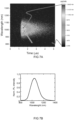
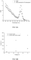
- FIG 7A depicts a streak camera image of the emission from the PbS QDs capped with cysteamine hydrochloride in water.
- the arrow follows a trajectory with increasing units in accordance with the color scale.
- FIG 7B depicts a photo-luminescence spectrum of the PbS QDs capped with cysteamine hydrochloride in water.
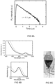
- FIG 8A depicts a Time-Resolved Photoluminescence (TRPL) a spectrum of the PbS QDs capped with cysteamine hydrochloride in water.
- TRPL Time-Resolved Photoluminescence
- the photo a 1L separation funnel comprising the biphasic mixture after the complete ligand exchange as shown in FIG 8C illustrates the possibility to upscale the process.
- FIG 8B depicts absorption spectra of PbS QDs capped with native oleic acid in hexane (solid black line) and after the ligand exchange with cysteamine hydrochloride in water (dashed grey line).
- FIG 6C displays a photograph of a vial 50 comprising the second phase liquid 20 and the quantum dots 1 that are capped with a shell of second ligands after centrifugation at the bottom of the vial.
- FIG 6B displays a photograph of a vial 50 comprising an ink 100 comprising the quantum dots 1 that are capped with a shell of second ligands redispersed in water.
- FIG 6D displays a photograph of a vial 50 comprising an ink 100 comprising the CdSe quantum dots of the third example redispersed in water.
- a seventh example the ligand exchange process was repeated for PbS quantum dots capped with oleic acid using disulfide of cysteamine hydrochloride as second ligand.
- the disulfide of cysteamine hydrochloride was found to be poorly soluble in DMF, but was soluble in DMSO. Therefore the otherwise similar process was conducted using DMSO as solvent. Complete ligand exchange was observed and a pellet of PbS quantum dots that are capped with a shell of cysteamine hydrochloride ligands was obtained after centrifugation.
- the QDs and ink composition as described herein can be of particular benefit for optoelectronic devices.
- various aspects and benefits will be explained as to QDs according to the invention and their application in optoelectronic devices such as field effect transistors, photo detectors, such as IR photo detectors and X-ray detectors, photodiodes, and solar cells. Unless otherwise specified the devices were prepared using commonly known procedures.
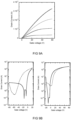
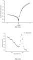
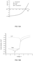
- FIG 9A illustrates output characteristics of an exemplary field-effect transistor, fabricated with PbS QDs capped cysteamine hydrochloride as active material. Note that the plot displays both the reverse and forward scans indicating that hysteresis is very low.
- FIG 9B depicts the transfer characteristics of the field-effect transistor. Solid lines represent the forward scans and the dashed lines represent the reverse voltage scan. The linear mobility for electrons was found to be 3.1E-4 cm 2 /Vs.
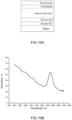
- FIG 10A schematically depicts the device schematics of an infrared photodetector made with a photoactive layer comprising cysteamine HCl-capped PbS QDs according to the invention.
- the QDs were spray-coated in air on top of a Glass/ITO substrate coated by 100 nm ZnO nanoparticles to form 600 nm thick layer.
- the device was completed by thermal evaporation of 7 nm MoOx and 80 nm gold top contact.
- FIG 10B demonstrates optical properties of cysteamine HCl-capped quantum dots, deposited in a thin film (600 nm) as a photoactive layer in the infrared photodetector. It shows a clear absorption peak in infrared region (at 1450 nm), which is slightly red-shifted compared to original OA-capped quantum dot solution (at 1420 nm). The light scattering in the quantum dot film causes increased measured absorption values, and explains non-zero absorption at the wavelength longer than the absorption peak position.
- FIG 11A depicts a JV curve of the photodiode in dark.
- the device has an off-current of 3.4*10E-4 mA/cm2 for 1V reverse voltage bias, which is a low value for quantum dots with the absorption properties shown in figure 10B .
- the diode shows the current rectification ratio of 6.2*10E3, which demonstrates good charge transport in the forward direction and efficient charge carrier blocking in reverse direction.
- the EQE values were calculated ( FIG 12A ).
- D* the device was measured under reverse voltage bias in dark and under monochromatic illumination.
- FIG 12B displaying the dark current of the device and the current measured under 1450 nm monochromatic light (860 nW) under reverse voltage bias of 0.1 V, 0.5 V, and 1 V.
- FIG 13A displays JV characteristics under AM 1.5 light illumination of a solar cell comprising an active layer with cysteamine HCl-capped PbS QDs according to the invention.
- the device was found to have a short circuit current J sc of 18.6 mA/cm ⁇ 2; an open circuit potential V oc of 0.5V; a fill factor FF of 0.48; and a maximum power point (MPP) at 4.46 mW/cm 2 .
- FIG 13B depicts the JV-characteristics of an X-ray sensitive photodiode (as shown in FIG 5 ) in dark (bottom trace) and under white light illumination (top trace).
- the thickness of QD layer is 600 nm.
- FIG 14A depicts the current response of the device to X-ray pulses ( ⁇ 10s each) (HP Faxitron 43855A, tungsten anode, 58kV voltage, 2 mA current) for 1 V reverse voltage. Rise time is limited by the source turning on time, and fall time is limited by the measurement equipment.
- FIG 14B displays the performance in terms of the leakage current and X-ray response current.
- cysteamine hydrochloride capped quantum dots As comparative examples inventors attempted to prepare cysteamine hydrochloride capped quantum dots according to the method disclosed by Hak Soo Choi et al (Nature biotechnology 25; 1165-1170 (2007 ). To this end equal volumes of a chloroform solution of oleate-capped PbS QDs were mixed with 30 mM solutions of cysteamine hydrochloride dissolved in watery PBS buffer. However, even after prolonged stirring (>12h), no ligand exchange (LE) was observed. In contrast, the method of ligand exchange according to the invention was complete after about 30 seconds.
Landscapes
- Chemical & Material Sciences (AREA)
- Engineering & Computer Science (AREA)
- Materials Engineering (AREA)
- Organic Chemistry (AREA)
- Inorganic Chemistry (AREA)
- Life Sciences & Earth Sciences (AREA)
- Wood Science & Technology (AREA)
- Physics & Mathematics (AREA)
- Electromagnetism (AREA)
- Chemical Kinetics & Catalysis (AREA)
- General Chemical & Material Sciences (AREA)
- Manufacturing & Machinery (AREA)
- Crystallography & Structural Chemistry (AREA)
- Nanotechnology (AREA)
- Inks, Pencil-Leads, Or Crayons (AREA)
Claims (15)
- Procédé de fabrication d'une composition d'encre (100) pour un dépôt d'une couche photoactive d'un dispositif optoélectronique, le procédé comprenant les étapes consistant à- fournir un liquide de première phase (10) comprenant un solvant non polaire (11) avec des nanoparticules (1) dispersées dans le solvant non polaire, lesquelles nanoparticules sont coiffées d'une enveloppe (2s) de premiers ligands (2), les premiers ligands (2) comprenant un groupe de tête de liaison de surface (2h) et une queue alkyle ou alcényle (2t) pour, au moins initialement, maintenir les nanoparticules (1) dans une suspension colloïdale dans le solvant non polaire (11) ;- fournir un liquide de seconde phase (20) comprenant un premier solvant polaire (21) dans lequel sont dissous des seconds ligands (3), les seconds ligands présentant une architecture moléculaire comprenant :• un groupe de tête thiol (3h) pour une liaison à un site de surface de ladite nanoparticule (1) ;• un groupe de queue chargé ioniquement (3t) auquel est associé un contre-ion (3c) ; et• un espaceur alkyle séparant le groupe de tête et le groupe de queue, présentant un nombre total d'atomes de carbone dans une plage allant de 1 à 3,- un procédé d'échange de ligands biphasique dans lequel les seconds ligands déplacent les premiers ligands qui sont liés aux nanoparticules (1), en libérant ainsi les premiers ligands vers le liquide de première phase (10), le procédé d'échange de ligands biphasique comprenant une mise en contact des liquides de première (10) et de seconde phase (20) pour former une dispersion des nanoparticules (1) qui sont coiffées d'une enveloppe (3s) des seconds ligands (3) dans le liquide de seconde phase.
- Procédé selon la revendication précédente, dans lequel les seconds ligands (3) sont :
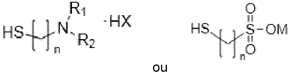 « n » est compris entre 1 et 3 ;« R1 » et « R1 » sont choisis chacun indépendamment parmi H et méthyle ;« X » est un halogénure, de préférence CI ; et« M » est un métal alcalin, de préférence Na ou K.
 - Procédé selon la revendication 1 ou 2, comprenant les étapes consistant à- séparer les nanoparticules qui sont coiffées d'une enveloppe des seconds ligands à partir du premier solvant polaire ; et- redisperser les nanoparticules séparées (1) dans un milieu liquide imprimable (30) comprenant un deuxième solvant polaire.
- Procédé selon l'une quelconque des revendications précédentes, dans lequel :- le premier solvant polaire comprend du N,N-diméthylformamide, du N-méthylformamide, ou une combinaison de ceux-ci ; et- le deuxième solvant polaire comprend un alcool inférieur au moins partiellement fluoré, ou un mélange d'eau et d'éthylène glycol, dans lequel la fraction volumique d'éthylène glycol dans le mélange est comprise entre cinq et cinquante pour cent.
- Procédé selon l'une quelconque des revendications précédentes, comprenant la dissolution d'une fraction disulfure dans le liquide de second phase (20) de manière à former les seconds ligands en tant que produits de dissociation de la fraction disulfure.
- Procédé selon l'une quelconque des revendications précédentes, le procédé comprenant les étapes consistant à- déterminer une quantité du second ligand qui doit être comprise dans le premier solvant polaire (21) par rapport à une quantité nécessaire pour coiffer complètement les nanoparticules (1) avec une enveloppe (3s) des seconds ligands ; et- fournir au liquide de seconde phase (20) comprenant le premier solvant polaire (21) des seconds ligands (3) en une quantité inférieure à 1,05 fois la quantité prédéterminée.
- Procédé selon l'une quelconque des revendications précédentes, comprenant le lavage des nanoparticules séparées avec une ou plusieurs parties d'un solvant pour le premier ligand, et/ou comprenant l'ajout d'un troisième solvant au liquide de première phase (10) et au liquide de seconde phase (20), le troisième solvant étant miscible à la fois avec le solvant non polaire (11) et le premier solvant polaire (21).
- Composition d'encre à utiliser dans le dépôt d'une couche photoactive d'un dispositif optoélectronique, la composition d'encre comprenant- une suspension colloïdale de nanoparticules dans un milieu liquide imprimable (30) comprenant un solvant polaire, dans laquelle les nanoparticules sont coiffées d'une enveloppe de seconds ligands (3) remplaçant une enveloppe initiale de premiers ligands différents, dans laquelle les seconds ligands présentent une architecture moléculaire comprenant• un groupe de tête thiol (3h) lié à un site de surface de ladite nanoparticule (1) ;• un groupe de queue chargé ioniquement (3t) auquel est associé un contre-ion (3c) ; et• un espaceur alkyle séparant le groupe de tête et le groupe de queue présentant un nombre total d'atomes de carbone n dans une plage allant de 1 à 3,dans laquelle le solvant polaire comprend un alcool inférieur au moins partiellement fluoré, ou un mélange d'eau et d'éthylène glycol, dans laquelle la fraction volumique d'éthylène glycol dans le mélange se trouve dans une plage allant de cinq à cinquante pour cent, dans laquelle les premiers ligands et les seconds ligands libres non liés sont présents dans la composition d'encre à une concentration < 10 µM.
- Composition d'encre selon la revendication précédente, dans laquelle la composition est essentiellement dépourvue de premiers ligands et de seconds ligands libres non liés.
- Composition d'encre selon l'une quelconque des revendications précédentes, dans lequel les seconds ligands (3) sont :
 « n » est compris entre 1 et 3 ;« R1 » et « R1 » sont choisis chacun indépendamment parmi H et méthyle ;« X » est un halogénure, de préférence CI ;« M » est un métal alcalin, de préférence Na ou K.
 - Composition d'encre selon l'une quelconque des revendications précédentes, comprenant un additif de pyrrolidone et/ou comprenant un ou plusieurs additifs polymères (33).
- Composition d'encre selon l'une quelconque des revendications précédentes, comprenant un dopant de type p (31) ou un dopant de type n.
- Procédé de fabrication d'un dispositif d'imagerie (1000) comprenant un empilement de couches photoactives (110) comprenant au moins une couche photoactive de type p (110p) et une couche photoactive de type n (110n), le procédé comprenant les étapes consistant à- déposer une ou plusieurs couches de la composition d'encre comprenant un dopant de type p selon la revendication précédente ; et- déposer une ou plusieurs couches de la composition d'encre comprenant un dopant de type n selon la revendication précédente ;- les couches déposées formant un empilement de couches photoactives (110) comprenant au moins une couche photoactive de type p (110p) et une couche photoactive de type n (110n), dans lequel les couches photoactives sont amorphes, comprenant une structure désordonnée de nanoparticules formées par des points quantiques résultant du dépôt en appliquant les compositions d'encre respectives comprenant des points quantiques colloïdaux.
- Composition sèche, comprenant les nanoparticules qui sont coiffées d'une enveloppe de second ligands (3) pouvant être obtenue par l'intermédiaire des étapes consistant à- effectuer le procédé selon l'une quelconque des revendications 1 à 7 ;- séparer les nanoparticules qui sont coiffées d'une enveloppe des seconds ligands à partir du premier solvant polaire du liquide de seconde phase ; et- sécher les nanoparticules séparées.
- Utilisation de la composition sèche selon la revendication précédente dans la fabrication d'une composition d'encre imprimable (100) en dispersant la composition sèche dans un solvant polaire comprenant un alcool inférieur au moins partiellement fluoré, ou un mélange d'eau et d'éthylène glycol, dans laquelle la fraction volumique d'éthylène glycol dans le mélange se trouve dans une plage allant de cinq à cinquante pour cent.
Applications Claiming Priority (2)
| Application Number | Priority Date | Filing Date | Title |
|---|---|---|---|
| EP20159348.0A EP3872146A1 (fr) | 2020-02-25 | 2020-02-25 | Encres à nanoparticules colloïdales pour l'impression de couches actives dans un dispositif optoélectronique |
| PCT/NL2021/050124 WO2021172986A1 (fr) | 2020-02-25 | 2021-02-24 | Encres à nanoparticules colloïdales pour l'impression de couches actives dans un dispositif optoélectronique |
Publications (3)
| Publication Number | Publication Date |
|---|---|
| EP4110883A1 EP4110883A1 (fr) | 2023-01-04 |
| EP4110883B1 true EP4110883B1 (fr) | 2024-09-25 |
| EP4110883C0 EP4110883C0 (fr) | 2024-09-25 |
Family
ID=69740163
Family Applications (2)
| Application Number | Title | Priority Date | Filing Date |
|---|---|---|---|
| EP20159348.0A Withdrawn EP3872146A1 (fr) | 2020-02-25 | 2020-02-25 | Encres à nanoparticules colloïdales pour l'impression de couches actives dans un dispositif optoélectronique |
| EP21708403.7A Active EP4110883B1 (fr) | 2020-02-25 | 2021-02-24 | Encres à nanoparticules colloïdales pour l'impression de couches actives dans un dispositif optoélectronique |
Family Applications Before (1)
| Application Number | Title | Priority Date | Filing Date |
|---|---|---|---|
| EP20159348.0A Withdrawn EP3872146A1 (fr) | 2020-02-25 | 2020-02-25 | Encres à nanoparticules colloïdales pour l'impression de couches actives dans un dispositif optoélectronique |
Country Status (4)
| Country | Link |
|---|---|
| US (1) | US20230139873A1 (fr) |
| EP (2) | EP3872146A1 (fr) |
| CN (1) | CN115349005B (fr) |
| WO (1) | WO2021172986A1 (fr) |
Families Citing this family (9)
| Publication number | Priority date | Publication date | Assignee | Title |
|---|---|---|---|---|
| US11559268B2 (en) | 2015-01-12 | 2023-01-24 | Real Time Imaging Technologies, Llc | Low-dose x-ray imaging system |
| US20230082643A1 (en) * | 2021-09-13 | 2023-03-16 | Lawrence Livermore National Security, Llc | Surface treatment for colloidal stability of in-solution ligand exchanged quantum dots |
| KR20230044081A (ko) * | 2021-09-24 | 2023-04-03 | 삼성디스플레이 주식회사 | 잉크 조성물, 발광 소자 및 그 발광 소자의 제조 방법 |
| EP4441795A4 (fr) | 2021-12-01 | 2025-11-26 | Swir Vision Systems Inc | Systèmes de détection de profondeur optique faisant appel à des photodétecteurs à points quantiques colloïdaux grande vitesse |
| CN115109583B (zh) * | 2022-06-15 | 2025-07-18 | 广州光达创新科技有限公司 | 一种胶体量子点材料及其制备方法,以及其在胶体量子点光探测器和阵列中的应用 |
| JP2024017714A (ja) * | 2022-07-28 | 2024-02-08 | 三菱ケミカル株式会社 | 導電体界面修飾用材料、半導体層、光電変換素子及びその製造方法 |
| US20240147824A1 (en) * | 2022-10-11 | 2024-05-02 | Samsung Display Co., Ltd. | Electronic apparatus including organic photodiode and organic light-emitting device |
| WO2025082611A1 (fr) * | 2023-10-20 | 2025-04-24 | Qdi Systems B.V | Nanocristaux de chalcogénure de pb coiffés par des ions colloïdaux pour applications radiographiques |
| TW202600781A (zh) * | 2024-03-08 | 2026-01-01 | 日商富士軟片股份有限公司 | 分散液、光電轉換膜、光電轉換膜之製造方法、光檢測元件及影像感測器 |
Family Cites Families (15)
| Publication number | Priority date | Publication date | Assignee | Title |
|---|---|---|---|---|
| US6251303B1 (en) | 1998-09-18 | 2001-06-26 | Massachusetts Institute Of Technology | Water-soluble fluorescent nanocrystals |
| US7746681B2 (en) | 2005-01-07 | 2010-06-29 | Invisage Technologies, Inc. | Methods of making quantum dot films |
| KR100777662B1 (ko) * | 2006-06-14 | 2007-11-29 | 삼성전기주식회사 | 잉크젯용 전도성 잉크 조성물 |
| JP5669720B2 (ja) * | 2008-03-25 | 2015-02-12 | ゼロックス コーポレイションXerox Corporation | シリカでカプセル化された有機ナノ顔料と同顔料の作製法 |
| KR20110078007A (ko) * | 2009-12-30 | 2011-07-07 | 삼성전기주식회사 | 금속나노입자가 분산된 잉크젯용 잉크의 제조방법 |
| KR101874413B1 (ko) * | 2011-10-18 | 2018-07-05 | 삼성전자주식회사 | 무기 리간드를 갖는 양자점 및 그의 제조방법 |
| CN103127744B (zh) * | 2011-11-28 | 2014-12-10 | 中国科学院金属研究所 | 一种将油相纳米颗粒转移到水相中的方法 |
| EP3102647B1 (fr) * | 2014-02-04 | 2020-11-04 | Lumileds Holding B.V. | Ligands composites inorganiques à base d'oxo et d'hydroxo pour des points quantiques |
| US9666768B2 (en) * | 2014-02-07 | 2017-05-30 | Nanoco Technologies Ltd. | Quantum dot nanoparticles having enhanced stability and luminescence efficiency |
| US10544168B2 (en) * | 2016-06-15 | 2020-01-28 | Alliance For Sustainable Energy, Llc | Ligand-exchangeable nanoparticles and methods of making the same |
| CN106367060B (zh) * | 2016-08-30 | 2020-03-10 | Tcl集团股份有限公司 | 一种量子点配体交换的方法 |
| CN106479503A (zh) * | 2016-09-29 | 2017-03-08 | Tcl集团股份有限公司 | 一种量子点固态膜及其制备方法 |
| CN108192591B (zh) * | 2018-01-03 | 2020-05-26 | 京东方科技集团股份有限公司 | 量子点配体的交换方法以及用于量子点配体交换的装置 |
| CN110386886B (zh) * | 2018-04-16 | 2021-12-07 | 中国科学院理化技术研究所 | 快速、高效且通用的交换胶体纳米晶体表面配体的方法 |
| WO2019203240A1 (fr) * | 2018-04-17 | 2019-10-24 | 昭栄化学工業株式会社 | Procédé de production de nanoparticules, nanoparticules, système de production de nanoparticules et procédé de production d'un mélange d'encres à nanoparticules |
-
2020
- 2020-02-25 EP EP20159348.0A patent/EP3872146A1/fr not_active Withdrawn
-
2021
- 2021-02-24 WO PCT/NL2021/050124 patent/WO2021172986A1/fr not_active Ceased
- 2021-02-24 CN CN202180016032.9A patent/CN115349005B/zh active Active
- 2021-02-24 US US17/801,651 patent/US20230139873A1/en active Pending
- 2021-02-24 EP EP21708403.7A patent/EP4110883B1/fr active Active
Also Published As
| Publication number | Publication date |
|---|---|
| US20230139873A1 (en) | 2023-05-04 |
| EP3872146A1 (fr) | 2021-09-01 |
| EP4110883A1 (fr) | 2023-01-04 |
| EP4110883C0 (fr) | 2024-09-25 |
| WO2021172986A1 (fr) | 2021-09-02 |
| CN115349005A (zh) | 2022-11-15 |
| CN115349005B (zh) | 2025-02-21 |
Similar Documents
| Publication | Publication Date | Title |
|---|---|---|
| EP4110883B1 (fr) | Encres à nanoparticules colloïdales pour l'impression de couches actives dans un dispositif optoélectronique | |
| Goswami et al. | Graphene quantum dot-sensitized ZnO-nanorod/GaN-nanotower heterostructure-based high-performance UV photodetectors | |
| Stroyuk et al. | Solar light harvesting with multinary metal chalcogenide nanocrystals | |
| Beek et al. | Efficient hybrid solar cells from zinc oxide nanoparticles and a conjugated polymer | |
| Talapin et al. | Prospects of colloidal nanocrystals for electronic and optoelectronic applications | |
| Moulé et al. | Hybrid solar cells: basic principles and the role of ligands | |
| CN100380684C (zh) | 半导体-纳米晶体/共轭聚合物薄膜 | |
| JP2013506302A (ja) | 量子ドット−フラーレン接合光電子素子 | |
| US20040183070A1 (en) | Solution processed pentacene-acceptor heterojunctions in diodes, photodiodes, and photovoltaic cells and method of making same | |
| Song et al. | High-performance visible-blind UV phototransistors based on n-type naphthalene diimide nanomaterials | |
| JP2015537378A (ja) | 溶液プロセスによる量子ドットを利用した中間帯半導体、ヘテロ接合、及び光電子デバイス、並びに関連する方法 | |
| CN112567536A (zh) | 基于二维量子点的光电探测器 | |
| WO2017212397A1 (fr) | Matériaux à base pérovskite composites, procédés de production et procédés d'utilisation | |
| Li et al. | Ternary CuZnS nanocrystals: synthesis, characterization, and interfacial application in perovskite solar cells | |
| Wang et al. | Eco-friendly visible-wavelength photodetectors based on bandgap engineerable nanomaterials | |
| Gonzalez-Carrero et al. | Colloids of naked CH3NH3PbBr3 perovskite nanoparticles: synthesis, stability, and thin solid film deposition | |
| Izadpour et al. | Plasmonic enhancement of colloidal quantum dot infrared photodetector photosensitivity | |
| Wang et al. | Synergic surface modifications of PbS quantum dots by sodium acetate in solid-state ligand exchange toward short-wave infrared photodetectors | |
| US20170040120A1 (en) | Electronic device comprising nanogap electrodes and nanoparticles | |
| Ajuria et al. | Novel ZnO nanostructured electrodes for higher power conversion efficiencies in polymeric solar cells | |
| Franchini et al. | Phototransport in networks of tetrapod-shaped colloidal semiconductor nanocrystals | |
| Radychev et al. | Photovoltaic response of hybrid solar cells with alloyed ZnS–CuInS2 nanorods | |
| WO2015162184A1 (fr) | Dispositif électronique comprenant des électrodes à nano-espacement et des nanoparticules | |
| Praisudan et al. | Enhanced Photoresponse in Type-II MoSe2/WS2 Layered Heterostructures | |
| Zhang et al. | Cold field emission dominated photoconductivity in ordered three-dimensional assemblies of octapod-shaped CdSe/CdS nanocrystals |
Legal Events
| Date | Code | Title | Description |
|---|---|---|---|
| STAA | Information on the status of an ep patent application or granted ep patent |
Free format text: STATUS: UNKNOWN |
|
| STAA | Information on the status of an ep patent application or granted ep patent |
Free format text: STATUS: THE INTERNATIONAL PUBLICATION HAS BEEN MADE |
|
| PUAI | Public reference made under article 153(3) epc to a published international application that has entered the european phase |
Free format text: ORIGINAL CODE: 0009012 |
|
| STAA | Information on the status of an ep patent application or granted ep patent |
Free format text: STATUS: REQUEST FOR EXAMINATION WAS MADE |
|
| 17P | Request for examination filed |
Effective date: 20220915 |
|
| AK | Designated contracting states |
Kind code of ref document: A1 Designated state(s): AL AT BE BG CH CY CZ DE DK EE ES FI FR GB GR HR HU IE IS IT LI LT LU LV MC MK MT NL NO PL PT RO RS SE SI SK SM TR |
|
| DAV | Request for validation of the european patent (deleted) | ||
| DAX | Request for extension of the european patent (deleted) | ||
| STAA | Information on the status of an ep patent application or granted ep patent |
Free format text: STATUS: EXAMINATION IS IN PROGRESS |
|
| 17Q | First examination report despatched |
Effective date: 20230817 |
|
| GRAP | Despatch of communication of intention to grant a patent |
Free format text: ORIGINAL CODE: EPIDOSNIGR1 |
|
| STAA | Information on the status of an ep patent application or granted ep patent |
Free format text: STATUS: GRANT OF PATENT IS INTENDED |
|
| INTG | Intention to grant announced |
Effective date: 20240419 |
|
| GRAS | Grant fee paid |
Free format text: ORIGINAL CODE: EPIDOSNIGR3 |
|
| GRAA | (expected) grant |
Free format text: ORIGINAL CODE: 0009210 |
|
| STAA | Information on the status of an ep patent application or granted ep patent |
Free format text: STATUS: THE PATENT HAS BEEN GRANTED |
|
| RAP3 | Party data changed (applicant data changed or rights of an application transferred) |
Owner name: QDI SYSTEMS B.V. Owner name: RIJKSUNIVERSITEIT GRONINGEN |
|
| AK | Designated contracting states |
Kind code of ref document: B1 Designated state(s): AL AT BE BG CH CY CZ DE DK EE ES FI FR GB GR HR HU IE IS IT LI LT LU LV MC MK MT NL NO PL PT RO RS SE SI SK SM TR |
|
| REG | Reference to a national code |
Ref country code: GB Ref legal event code: FG4D |
|
| RIN1 | Information on inventor provided before grant (corrected) |
Inventor name: BEDERAK, DMYTRO YAROSLAVOVYCH Inventor name: SHULGA, ARTEM GENNADIIOVYCH Inventor name: LOI, MARIA ANTONIETTA |
|
| REG | Reference to a national code |
Ref country code: CH Ref legal event code: EP |
|
| REG | Reference to a national code |
Ref country code: DE Ref legal event code: R096 Ref document number: 602021019287 Country of ref document: DE |
|
| REG | Reference to a national code |
Ref country code: IE Ref legal event code: FG4D |
|
| U01 | Request for unitary effect filed |
Effective date: 20241021 |
|
| U07 | Unitary effect registered |
Designated state(s): AT BE BG DE DK EE FI FR IT LT LU LV MT NL PT RO SE SI Effective date: 20241105 |
|
| PG25 | Lapsed in a contracting state [announced via postgrant information from national office to epo] |
Ref country code: NO Free format text: LAPSE BECAUSE OF FAILURE TO SUBMIT A TRANSLATION OF THE DESCRIPTION OR TO PAY THE FEE WITHIN THE PRESCRIBED TIME-LIMIT Effective date: 20241225 |
|
| PG25 | Lapsed in a contracting state [announced via postgrant information from national office to epo] |
Ref country code: GR Free format text: LAPSE BECAUSE OF FAILURE TO SUBMIT A TRANSLATION OF THE DESCRIPTION OR TO PAY THE FEE WITHIN THE PRESCRIBED TIME-LIMIT Effective date: 20241226 |
|
| PG25 | Lapsed in a contracting state [announced via postgrant information from national office to epo] |
Ref country code: RS Free format text: LAPSE BECAUSE OF FAILURE TO SUBMIT A TRANSLATION OF THE DESCRIPTION OR TO PAY THE FEE WITHIN THE PRESCRIBED TIME-LIMIT Effective date: 20241225 |
|
| PG25 | Lapsed in a contracting state [announced via postgrant information from national office to epo] |
Ref country code: RS Free format text: LAPSE BECAUSE OF FAILURE TO SUBMIT A TRANSLATION OF THE DESCRIPTION OR TO PAY THE FEE WITHIN THE PRESCRIBED TIME-LIMIT Effective date: 20241225 Ref country code: NO Free format text: LAPSE BECAUSE OF FAILURE TO SUBMIT A TRANSLATION OF THE DESCRIPTION OR TO PAY THE FEE WITHIN THE PRESCRIBED TIME-LIMIT Effective date: 20241225 Ref country code: GR Free format text: LAPSE BECAUSE OF FAILURE TO SUBMIT A TRANSLATION OF THE DESCRIPTION OR TO PAY THE FEE WITHIN THE PRESCRIBED TIME-LIMIT Effective date: 20241226 |
|
| U20 | Renewal fee for the european patent with unitary effect paid |
Year of fee payment: 5 Effective date: 20250121 |
|
| PG25 | Lapsed in a contracting state [announced via postgrant information from national office to epo] |
Ref country code: IS Free format text: LAPSE BECAUSE OF FAILURE TO SUBMIT A TRANSLATION OF THE DESCRIPTION OR TO PAY THE FEE WITHIN THE PRESCRIBED TIME-LIMIT Effective date: 20250125 |
|
| PG25 | Lapsed in a contracting state [announced via postgrant information from national office to epo] |
Ref country code: SM Free format text: LAPSE BECAUSE OF FAILURE TO SUBMIT A TRANSLATION OF THE DESCRIPTION OR TO PAY THE FEE WITHIN THE PRESCRIBED TIME-LIMIT Effective date: 20240925 |
|
| PG25 | Lapsed in a contracting state [announced via postgrant information from national office to epo] |
Ref country code: ES Free format text: LAPSE BECAUSE OF FAILURE TO SUBMIT A TRANSLATION OF THE DESCRIPTION OR TO PAY THE FEE WITHIN THE PRESCRIBED TIME-LIMIT Effective date: 20240925 |
|
| PG25 | Lapsed in a contracting state [announced via postgrant information from national office to epo] |
Ref country code: PL Free format text: LAPSE BECAUSE OF FAILURE TO SUBMIT A TRANSLATION OF THE DESCRIPTION OR TO PAY THE FEE WITHIN THE PRESCRIBED TIME-LIMIT Effective date: 20240925 Ref country code: CZ Free format text: LAPSE BECAUSE OF FAILURE TO SUBMIT A TRANSLATION OF THE DESCRIPTION OR TO PAY THE FEE WITHIN THE PRESCRIBED TIME-LIMIT Effective date: 20240925 |
|
| PG25 | Lapsed in a contracting state [announced via postgrant information from national office to epo] |
Ref country code: SK Free format text: LAPSE BECAUSE OF FAILURE TO SUBMIT A TRANSLATION OF THE DESCRIPTION OR TO PAY THE FEE WITHIN THE PRESCRIBED TIME-LIMIT Effective date: 20240925 |
|
| PLBE | No opposition filed within time limit |
Free format text: ORIGINAL CODE: 0009261 |
|
| STAA | Information on the status of an ep patent application or granted ep patent |
Free format text: STATUS: NO OPPOSITION FILED WITHIN TIME LIMIT |
|
| 26N | No opposition filed |
Effective date: 20250626 |
|
| PG25 | Lapsed in a contracting state [announced via postgrant information from national office to epo] |
Ref country code: MC Free format text: LAPSE BECAUSE OF FAILURE TO SUBMIT A TRANSLATION OF THE DESCRIPTION OR TO PAY THE FEE WITHIN THE PRESCRIBED TIME-LIMIT Effective date: 20240925 |
|
| REG | Reference to a national code |
Ref country code: CH Ref legal event code: PL |
|
| PG25 | Lapsed in a contracting state [announced via postgrant information from national office to epo] |
Ref country code: CH Free format text: LAPSE BECAUSE OF NON-PAYMENT OF DUE FEES Effective date: 20250228 |
|
| PG25 | Lapsed in a contracting state [announced via postgrant information from national office to epo] |
Ref country code: HR Free format text: LAPSE BECAUSE OF FAILURE TO SUBMIT A TRANSLATION OF THE DESCRIPTION OR TO PAY THE FEE WITHIN THE PRESCRIBED TIME-LIMIT Effective date: 20240925 |
|
| PG25 | Lapsed in a contracting state [announced via postgrant information from national office to epo] |
Ref country code: IE Free format text: LAPSE BECAUSE OF NON-PAYMENT OF DUE FEES Effective date: 20250224 |
|
| U20 | Renewal fee for the european patent with unitary effect paid |
Year of fee payment: 6 Effective date: 20260225 |
|
| PGFP | Annual fee paid to national office [announced via postgrant information from national office to epo] |
Ref country code: GB Payment date: 20260220 Year of fee payment: 6 |