EP4111027B1 - Sicherheitsventil mit elektrischen aktuatoren - Google Patents
Sicherheitsventil mit elektrischen aktuatoren Download PDFInfo
- Publication number
- EP4111027B1 EP4111027B1 EP21759617.0A EP21759617A EP4111027B1 EP 4111027 B1 EP4111027 B1 EP 4111027B1 EP 21759617 A EP21759617 A EP 21759617A EP 4111027 B1 EP4111027 B1 EP 4111027B1
- Authority
- EP
- European Patent Office
- Prior art keywords
- actuator
- electric
- magnet
- downhole
- internal tubing
- Prior art date
- Legal status (The legal status is an assumption and is not a legal conclusion. Google has not performed a legal analysis and makes no representation as to the accuracy of the status listed.)
- Active
Links
Images









Classifications
-
- E—FIXED CONSTRUCTIONS
- E21—EARTH OR ROCK DRILLING; MINING
- E21B—EARTH OR ROCK DRILLING; OBTAINING OIL, GAS, WATER, SOLUBLE OR MELTABLE MATERIALS OR A SLURRY OF MINERALS FROM WELLS
- E21B34/00—Valve arrangements for boreholes or wells
- E21B34/06—Valve arrangements for boreholes or wells in wells
- E21B34/066—Valve arrangements for boreholes or wells in wells electrically actuated
-
- E—FIXED CONSTRUCTIONS
- E21—EARTH OR ROCK DRILLING; MINING
- E21B—EARTH OR ROCK DRILLING; OBTAINING OIL, GAS, WATER, SOLUBLE OR MELTABLE MATERIALS OR A SLURRY OF MINERALS FROM WELLS
- E21B34/00—Valve arrangements for boreholes or wells
- E21B34/06—Valve arrangements for boreholes or wells in wells
- E21B34/14—Valve arrangements for boreholes or wells in wells operated by movement of tools, e.g. sleeve valves operated by pistons or wire line tools
-
- E—FIXED CONSTRUCTIONS
- E21—EARTH OR ROCK DRILLING; MINING
- E21B—EARTH OR ROCK DRILLING; OBTAINING OIL, GAS, WATER, SOLUBLE OR MELTABLE MATERIALS OR A SLURRY OF MINERALS FROM WELLS
- E21B2200/00—Special features related to earth drilling for obtaining oil, gas or water
- E21B2200/05—Flapper valves
Definitions
- the present disclosure generally relates to safety valves, and more particularly to safety valves having electrical actuators and fully electric safety valves.
- Valves typically are used in a well for such purposes as fluid flow control, formation isolation, and safety functions.
- a common downhole valve is a hydraulically-operated valve, which is known for its reliable performance.
- hydraulically-operated valves have limitations.
- a hydraulically-operated valve is depth-limited due to the high hydrostatic pressure acting against the valve at large depths, which may diminish the effective hydraulic pressure that is available to operate the valve.
- the viscous control fluid in a long hydraulic line may cause unacceptably long operating times for certain applications.
- a long hydraulic line and the associated connections provide little or no mechanism to determine, at the surface of the well, what is the true state of the valve. For example, if the valve is a safety valve, there may be no way to determine the on-off position of the valve, the pressure across the valve and the true operating pressure at the valve's operator at the installed depth.
- Patent applications WO2011/094084 and US2013/0341034 describe valves in which an electrically operated actuator opens the valve by pushing an internal sleeve linearly to open a flapper (and hence the valve) and also compress a return spring.
- the flapper can be held in its open position by an electric magnet.
- US2013/0032355 , US2010/0025045 , GB2433523 , EP1252440 and WO2017/0204804 also disclose electrically operated valves.
- the present disclosure provides a downhole valve assembly comprising an actuator, and an electric safety valve which comprises a flapper, a return spring, and an internal tubing sleeve, wherein the actuator is configured to extend to move the internal tubing sleeve from a closed position to an open position, thereby compressing the return spring and causing the internal tubing sleeve to open the flapper; characterized in that the electric safety valve comprises an electric magnet configured to be activated to hold the internal tubing sleeve in the open position, thereby allowing the actuator to be retracted while the internal tubing sleeve remains in the open position with the flapper open.
- the actuator can be an electro hydraulic actuator, an electro mechanical actuator, or an electro hydraulic pump.
- the electric safety valve is fully electric and does not include any hydraulic components.
- the electric safety valve can further include downhole electronics configured to receive a signal from the surface and control the actuator.
- the electric magnet can be configured to magnetically couple to a corresponding magnet disposed in or on a flange of the internal tubing sleeve, the flange configured to compress the return spring when the electric safety valve is in the open position.
- the electric magnet can be disposed in, on, or adjacent a movable shaft of the actuator and configured to magnetically couple to a corresponding magnet disposed in a wall of the internal tubing sleeve.
- the electric magnet can be configured to be activated when the electric safety valve is in an open position, thereby allowing the actuator to be retracted while holding the internal tubing sleeve and flapper in the open position. In some configurations, the electric magnet is configured to be activated prior to extending the actuator and opening the electric safety valve, and during closure, the internal tubing sleeve is retracted prior to retraction of the actuator. Closing of the electric safety valve can be controlled by the electric magnet. The electric safety valve can be moved to a closed position by deactivating the electric magnet.
- Another aspect of this disclosure provides a method of operating an electric downhole safety valve, the electric downhole safety valve comprising a flapper, an internal tubing sleeve, a return spring, an actuator, and downhole electronics, wherein the method comprises providing a command from the surface to the downhole electronics; in response to the command from the surface, extending the actuator, thereby shifting the internal tubing sleeve from a closed position to an open position; compressing the return spring; and using the internal tubing sleeve to open the flapper; characterized in that the electric downhole safety valve further comprises an electric magnet and the method further comprises activating the electric magnet to hold the internal tubing sleeve in the open position and retracting the actuator while the internal tubing sleeve is held in the open position by the electric magnet.
- the method can include retracting the actuator while the internal tubing sleeve is held in the open position by the electric magnet.
- the method can include deactivating the electric magnet. Deactivating the electric magnet can allow the return spring to expand, thereby shifting the internal tubing sleeve to the closed position and allowing the flapper to close.
- the method can include activating the electric magnet prior to extending the actuator.
- the method can further include deactivating the electric magnet, allowing the return spring to expand, thereby shifting the internal tubing sleeve to the closed position, and allowing the flapper to close, while the actuator is extended; and retracting the actuator after the flapper is closed.
- connection As used herein, the terms “connect”, “connection”, “connected”, “in connection with”, and “connecting” are used to mean “in direct connection with” or “in connection with via one or more elements”; and the term “set” is used to mean “one element” or “more than one element”. Further, the terms “couple”, “coupling”, “coupled”, “coupled together”, and “coupled with” are used to mean “directly coupled together” or “coupled together via one or more elements”. As used herein, the terms “up” and “down”; “upper” and “lower”; “top” and “bottom”; and other like terms indicating relative positions to a given point or element are utilized to more clearly describe some elements.
- these terms relate to a reference point at the surface from which drilling operations are initiated as being the top point and the total depth being the lowest point, wherein the well (e.g., wellbore, borehole) is vertical, horizontal or slanted relative to the surface.
- the well e.g., wellbore, borehole
- Well completions often include various valves, such as safety valves and flow control valves.
- Downhole or sub-surface safety valves are often deployed in an upper part of a well completion to provide a barrier against uncontrolled flow below the valve.
- the valve must be able to operate in a failsafe mode to close and stop well production in case of an emergency.
- Typically such valves have been hydraulically operated.
- hydraulically operated valves have limitations. For example, the use of a hydraulically-operated valve is depth-limited due to the high hydrostatic pressure acting against the valve at large depths, which may diminish the effective hydraulic pressure that is available to operate the valve.
- the viscous control fluid in a long hydraulic line may cause unacceptably long operating times for certain applications.
- a long hydraulic line and the associated connections provide little or no mechanism to determine, at the surface of the well, what is the true state of the valve. For example, if the valve is a safety valve, there may be no way to determine the on-off position of the valve, the pressure across the valve and the true operating pressure at the valve's operator at the installed depth.
- electric completion systems can provide reduced capital expenditures, reduced operating expenditures, and reduced health, safety, and environmental problems. Electric completions can advantageously allow for the use of sensors and proactive decision making for well control.
- the present disclosure provides electric safety valves, systems (e.g., well completions) including such electric safety valves, and methods of operating electric safety valves.
- an inductive coupler is used with an electric safety valve or completion including an electric safety valve.
- the safety valves can have a flapper valve design.
- the present disclosure also provides an electro-magnet disconnect system. The disconnect system enables a safe and reliable closing mechanism capable of withstanding extreme slam shutting.
- FIGS 1A and 1B illustrate an example hydraulic safety valve having a flapper valve design in open and closed positions, respectively.
- the safety valve assembly includes a flapper 62, a return spring 72, a flow tube or sleeve 74, a piston 76, and a control line 78.
- the position (open or closed) of the flapper 62 is controlled via the flow tube or sleeve 74 sliding up and down inside the production tubing.
- the sleeve position is controlled or moved by the return spring 72 and/or the piston 76.
- the flapper 62 and return spring 72 are biased to the closed position.
- Hydraulic pressure applied from the surface via the control line 78 to the piston 76 causes the piston 76 to move the sleeve 74 downward, thereby compressing the return spring 72, and open the flapper 62.
- the sleeve 74 includes a radially outwardly projecting flange 75 that contacts and compresses the spring 72. Hydraulic pressure in the piston 76 maintains the sleeve's position and holds the valve open. As shown, at least a portion of the flapper 62 is shielded from flow through the production tubing by a portion of the sleeve 74, so the sleeve 74 protects the flapper 62 and tubing sealing area from flow erosion.
- the spring 72 bias pushes the sleeve 74 upward, allowing the flapper 62 to close.
- the spring 72 and/or flapper 62 bias to the closed position provides a failsafe for the valve, as the spring 72 ensures valve closure in case of emergency, such as a catastrophic event on the surface leading to a pressure drop or loss in the hydraulic control line 78.
- Figure 2 illustrates an example completion string including a safety valve according to the present disclosure positioned in a wellbore 10.
- the wellbore 10 may be part of a vertical well, deviated well, horizontal well, or a multilateral well.
- the wellbore 10 may be lined with casing 14 (or other suitable liner) and may include a production tubing 16 (or other type of pipe or tubing) that runs from the surface to a hydrocarbon-bearing formation downhole.
- a production packer 18 may be employed to isolate an annulus region 20 between the production tubing 16 and the casing 14.
- a subsurface safety valve assembly 22 may be attached to the tubing 20.
- the subsurface safety valve assembly 22 may include a flapper valve 24 or some other type of valve (e.g., a ball valve, sleeve valve, disk valve, and so forth).
- the flapper valve 24 is actuated opened or closed by an actuator assembly 26. During normal operation, the valve 24 is actuated to an open position to allow fluid flow in the bore of the production tubing 16.
- the safety valve 24 is designed to close should some failure condition be present in the wellbore 10 to prevent further damage to the well.
- the actuator assembly 26 in the safety valve assembly 22 may be electrically activated by signals provided by a controller 12 at the surface to the actuator assembly 26 via an electrical cable 28.
- the controller 12 is therefore operatively connected to the actuator assembly 26 via the cable 28.
- Other types of signals and/or mechanisms for remote actuation of the actuator assembly 26 are also possible.
- the controller 12 may be in the form of a computer-based control system, e.g. a microprocessor-based control system, a programmable logic control system, or another suitable control system for providing desired control signals to and/or from the actuator assembly 26.
- the control signals may be in the form of electric power and/or data signals delivered downhole to subsurface safety valve assembly 22 and/or uphole from subsurface safety valve assembly 22 .
- FIG. 3 illustrates an example flapper valve 24.
- the flapper 62 is pivotably mounted along a flapper housing 64 having an internal passage 66 therethrough and having a hard sealing surface 68.
- the flapper 62 is pivotably coupled to the flapper housing 64, for example, via a hinge pin 70, for movement between an open position and a closed position.
- the flapper 62 may be directly coupled to housing 64 or indirectly coupled to the housing 64 via an intermediate member.
- safety valves can be found in, for example, US 6,433,991 and WO 2019/089487 , the entirety of each of which is hereby incorporated by reference herein.
- actuators used with a subsurface safety valve it is contemplated that further embodiments may include actuators used with other types of downhole devices.
- Such other types of downhole devices may include, as examples, flow control valves, packers, sensors, pumps, and so forth.
- Other embodiments may include actuators used with devices outside the well environment.
- the actuator assembly 26 can be or include various types of actuators, such as electrical actuators.
- the actuator assembly 26 is or includes an electro hydraulic actuator (EHA), an electro mechanical actuator (EMA), or an electro hydraulic pump (EHP).
- EHA electro hydraulic actuator
- EMA electro mechanical actuator
- EHP electro hydraulic pump
- An EHA can allow for quick backdrive or actuation and therefore quick close functionality, which advantageously allows for rapid closure of the valve 24 when desired or required.
- the actuator assembly 26 is fully electric and the safety valve assembly 22 is fully electric. In other words, the safety valve assembly 22 includes no hydraulic components. In some such configurations, the actuator assembly 26 is or includes an EMA.
- the present disclosure advantageously provides a downhole electro-mechanical actuator in combination with an electrical magnet to control a valve, such as a downhole safety valve 22, for example as shown in Figures 4 and 8 .
- the safety valve can include various features of the configurations shown in Figures 1-3 .
- the safety valves of Figures 4 and 8 include, and their position is controlled by, an electric actuator 26 rather than hydraulic pressure applied via a control line from the surface.
- the actuator 26 is controlled and powered by a downhole electronics cartridge 30.
- the downhole electronics 30 can be connected to the surface via an electrical cable, for example, cable 28 (shown in Figure 2 ). In a closed mode or position of the safety valve, the actuator 26 is fully retracted such that the return spring 72 is fully expanded, and the flapper 62 is closed.
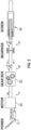
- FIG 5 schematically illustrates the principle of a linear electro-mechanical actuator, for example as may be included in valve assemblies according to the present disclosure, such as the valve assemblies of Figures 4 and 8 .
- an electrical motor 90 is powered and controlled by embedded downhole electronics 30. Motor rotation is converted into linear motion via a gear box 92 and screw mechanical assembly 94. In use, the motor 90 is activated by a surface command received and interpreted by the downhole electronics 30. The required linear force is obtained by the torque applied by the motor 90 at gear box entry.
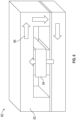
- Figure 6 schematically illustrates the principle of an electrical magnet 80, for example as may be included in valve assemblies according to the present disclosure, such as the valve assemblies of Figures 4 and 8 .
- the electrical magnet, or e-magnet 80 includes a magnetic core 82.
- the core 82 includes a coil of wires 84 having an appropriate number of turns to induce a required magnetic field when the coil 84 is powered on with a DC current.
- a force up to 40N can be induced by a magnetic field of 1 Tesla per cm 2 .
- core materials commonly used are known to saturate above 1.3 Tesla, a force up to 1000 N can be achieved with a core section in the order of 15 cm 2 .
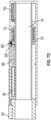
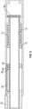
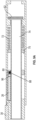
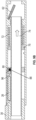
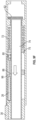
- Figures 7A-7F schematically illustrate operation of safety valves according to the present disclosure, such as the valve 22 of Figure 4 .
- Figure 7A shows the valve 22 in a closed position, with the electro-mechanical actuator (EMA) 26 in a fully retracted position and the E-magnet 80 not activated.
- Figure 7B shows the valve opening in response to a command from the surface to the downhole electronics 30. As shown, the EMA 26 is extending, and the E-magnet 80 is still not activated. Extension of the EMA 26 (e.g., a piston 96 of or coupled to the EMA 26) compresses the return spring 72.
- EMA electro-mechanical actuator
- Extension of the EMA 26 moves the internal tubing sleeve 74 toward, into contact with, and/or past the flapper 62 to open the flapper 62.
- the valve is fully opened, the EMA 26 is in the fully expanded position (and the return spring 72 can be fully compressed and/or the internal tubing sleeve 74 can be shifted to hold open and protect the flapper 62), and the E-magnet 80 is not yet activated.
- Figure 7D shows the valve fully opened, the EMA 26 fully extended, and the E-magnet 80 activated.
- the E-magnet 80 is configured to interact with, e.g., magnetically interact or couple with, a corresponding magnet or magnetic component 88 when activated.
- the magnet or magnetic component 88 is disposed in or on the flange 75 of the internal sleeve 74.
- the EMA 26 or piston or shaft 96 thereof, extends, the EMA 26 (or piston or shaft 96) axially displaces the flange 75, thereby compressing the spring 72.
- the magnet or magnetic component 88 is aligned with (e.g., radially aligned with and/or at generally or about the same axial depth as) the E-magnet 80, as shown in Figures 7C-7D .
- Activation of the E-magnet 80 can hold the internal tubing sleeve 74 in its shifted position (e.g., the position holding open and protecting the flapper 62, for example as shown in Figures 7C-7D ) via magnetic coupling between the E-magnet 80 and magnet or magnetic component 88.
- Figure 7E shows the EMA 26 (e.g., the piston or shaft 96) retracted, with the E-magnet 80 still activated, thereby maintaining the internal tubing 74 in its shifted position and the valve in a fully open position.
- Figure 7F shows the EMA 26 retracted and the E-magnet 80 de-activated.
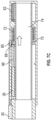
- Figure 8 illustrates another example electric safety valve 22 including an EMA 26 and an E-magnet 80.
- the E-magnet 80 is included in, on, or adj acent the piston or shaft 96 of the actuator 26.
- the E-magnet 80 is therefore in-line (e.g., axially aligned with or aligned along a common axis parallel to a longitudinal axis extending through the bore of the internal tubing sleeve 74) with the actuator 26, or piston or shaft 96 of the actuator 26.
- the corresponding magnet or magnetic component 88 is disposed within the body or wall of the internal tubing sleeve 74.
- Figures 9A-9G schematically illustrate operation of safety valves according to the present disclosure, such as the valve of Figure 8 .
- Figure 9A shows the valve in a closed position, with the electro-mechanical actuator (EMA) 26 in a fully retracted position.
- the E-magnet 80 is activated in order to initiate the coupling between the sleeve 74 and the actuator 26 and prepare the EMA 26 for actuation.
- Figure 9B shows the valve opening in response to a command from the surface to the downhole electronics 30.
- the E-magnet 80 is activated and the EMA 26 (e.g., the piston or shaft 96) is extending. Extension of the EMA 26 (e.g., the piston or shaft 96) compresses the return spring 72.
- the EMA 26 e.g., the piston or shaft 96
- Extension of the EMA 26 moves the internal tubing sleeve 74 toward, into contact with, and/or past the flapper 62 to open the flapper 62.
- the valve 22 is fully opened, the EMA 26 is in the fully expanded position (and the return spring 72 can be fully compressed and/or the internal tubing sleeve 74 can be shifted to hold open and protect the flapper 62), and the E-magnet 80 is kept activated.
- the E-magnet 80 can hold the internal tubing sleeve 74 in its shifted position (e.g., the position holding open and protecting the flapper 62, for example as shown in Figure 9C ).
- the motor can be shut-in.
- the valve is monitored for EMA back-drive, and if back-drive is detected, the EMA 26 can be powered on and actuated to the proper shaft position.
- FIGS 9D-9F show the valve closure mode via de-activation of the e-magnet 80.
- Closure mode can be triggered intentionally or automatically in the case of electrical shut-down (failsafe mode).
- De-activation of the E-magnet 80 releases the magnetic coupling with the internal sleeve 74, allowing the return spring 72 to expand and bias the internal sleeve 74 back to its original, closed position, and allowing the flapper 62 to close such that the valve is in a fully closed position or state ( Figure 9F ).
- the e-magnet 80 is magnetically decoupled from the actuator 26, the slam force is not transmitted to EMA shaft 96.
- FIG. 9G shows the valve fully closed with the EMA 26 (e.g., shaft or piston 96) retracted and the e-magnet 80 de-activated.
- the valve 22 can be re-opened by repeating the process shown in Figures 9A-9C .
- the e-magnet 80 can be released or powered off for valve shut-in to ensure failsafe operating mode.
- the e-magnet 80 can be strong enough to keep the spring 72 compressed. In some configurations, several magnets can be combined to achieve the desired or required strength.
- the e-magnet 80 retaining force (e.g., on the internal tubing sleeve 74 and/or spring 72) can be combined with additional mechanical friction if needed to compress the return spring 72.
- the e-magnet 80 is disposed in a housing mandrel (a non-moving part), which can facilitate connection to the downhole electronics 30. In other configurations, the e-magnet 80 is disposed on the shaft or piston 96 of the actuator 26 (a moving part).
- valve shut-in is not under control of the EMA 26, but instead advantageously under control of e-magnet 80 power release only. In other configurations, valve shut-in can be under control of both the EMA 26 and the e-magnet 80.
- the terms “generally parallel” and “substantially parallel” or “generally perpendicular” and “substantially perpendicular” refer to a value, amount, or characteristic that departs from exactly parallel or perpendicular, respectively, by less than or equal to 15 degrees, 10 degrees, 5 degrees, 3 degrees, 1 degree, or 0.1 degree.
Landscapes
- Geology (AREA)
- Life Sciences & Earth Sciences (AREA)
- Engineering & Computer Science (AREA)
- Mining & Mineral Resources (AREA)
- Environmental & Geological Engineering (AREA)
- Fluid Mechanics (AREA)
- Physics & Mathematics (AREA)
- General Life Sciences & Earth Sciences (AREA)
- Geochemistry & Mineralogy (AREA)
- Magnetically Actuated Valves (AREA)
- Lift Valve (AREA)
- Electrically Driven Valve-Operating Means (AREA)
- Fluid-Pressure Circuits (AREA)
- Actuator (AREA)
Claims (14)
- Bohrlochventilanordnung (22), umfassend:einen Aktuator (26), undein elektrisches Sicherheitsventil (24), umfassend eine Klappe (62), eine Rückstellfeder (72) und eine innere Rohrhülse (74),wobei der Aktuator (26) konfiguriert ist, um sich auszufahren, um die innere Rohrhülse aus einer geschlossenen Position in eine geöffnete Position zu bewegen, wodurch die Rückstellfeder (72) komprimiert wird und bewirkt wird, dass die innere Rohrhülse (74) die Klappe (62) öffnet;dadurch gekennzeichnet, dass das elektrische Sicherheitsventil (24) einen Elektromagneten (80) umfasst, der konfiguriert ist, um aktiviert zu werden, um die innere Rohrhülse in der geöffneten Position zu halten, wodurch ermöglicht wird, dass der Aktuator (26) zurückgezogen wird, während die innere Rohrhülse (74) in der geöffneten Position verbleibt, wobei die Klappe (62) geöffnet ist.
- Bohrlochventilanordnung nach Anspruch 1, wobei der Aktuator (26) ein elektrohydraulischer Aktuator ist.
- Bohrlochventilanordnung nach Anspruch 1, wobei der Aktuator (26) ein elektromechanischer Aktuator ist und wobei die Bohrlochventilanordnung (22) vollständig elektrisch ist, ohne hydraulische Komponenten.
- Bohrlochventilanordnung nach Anspruch 1, das elektrische Sicherheitsventil (24) ferner umfassend Bohrlochelektronik (30), wobei die Bohrlochelektronik (30) konfiguriert ist, um ein Signal von der Oberfläche zu empfangen und den Aktuator (26) zu steuern.
- Bohrlochventilanordnung nach Anspruch 1, wobei das Schließen des elektrischen Sicherheitsventils (24) durch den Elektromagneten (80) gesteuert wird und das elektrische Sicherheitsventil (24) durch ein Deaktivieren des Elektromagneten in eine geschlossene Position bewegt wird.
- Bohrlochventilanordnung nach Anspruch 1, wobei der Elektromagnet (80) konfiguriert ist, um eine magnetische Kopplung mit einem entsprechenden Magneten herzustellen, der in oder auf einem Flansch der inneren Rohrhülse (74) angeordnet ist, wobei der Flansch konfiguriert ist, um die Rückstellfeder (72) zu komprimieren, wenn sich das elektrische Sicherheitsventil (24) in der geöffneten Position befindet.
- Bohrlochventilanordnung nach Anspruch 1, wobei der Elektromagnet in, auf oder angrenzend an einen bewegbaren Schaft des Aktuators (26) angeordnet und konfiguriert ist, um eine magnetische Kopplung mit einem entsprechenden Magneten herzustellen, der in einer Wand der inneren Rohrhülse angeordnet ist.
- Verfahren zum Betreiben eines elektrischen Bohrlochsicherheitsventils (24), das elektrische Bohrlochsicherheitsventil (24) umfassend eine Klappe (62), eine innere Rohrhülse, eine Rückstellfeder (72), einen Aktuator (26) und Bohrlochelektronik, das Verfahren umfassend:Bereitstellen eines Befehls von der Oberfläche an die Bohrlochelektronik;als Reaktion auf den Befehl von der Oberfläche, Ausfahren des Aktuators, wodurch die innere Rohrhülse aus einer geschlossenen Position in eine geöffnete Position verschoben wird, Verwenden der inneren Rohrhülse, um die Klappe (62) zu öffnen, und Komprimieren der Rückstellfeder (72);dadurch gekennzeichnet, dass das elektrische Bohrlochsicherheitsventil (24) ferner einen Elektromagneten (80) umfasst, und das Verfahren ferner das Aktivieren des Elektromagneten (80), um die innere Rohrhülse (74) in der geöffneten Position zu halten, und das Zurückziehen des Aktuators (26) umfasst, während die innere Rohrhülse (74) durch den Elektromagneten (80) in der geöffneten Position gehalten wird.
- Verfahren nach Anspruch 8, wobei die innere Rohrhülse (74) einen Flansch umfasst, der konfiguriert ist, um die Rückstellfeder (72) zu komprimieren, wenn sich das elektrische Sicherheitsventil (24) in der geöffneten Position befindet, und das Verfahren das Aktivieren des Elektromagneten (80) umfasst, wenn sich das elektrische Sicherheitsventil (24) in der geöffneten Position befindet, woraufhin der Elektromagnet (80) eine magnetische Kopplung mit einem entsprechenden Magneten herstellt, der in oder auf dem Flansch der inneren Rohrhülse (74) angeordnet ist, und dadurch das elektrische Sicherheitsventil (24) in der geöffneten Position hält.
- Verfahren nach Anspruch 8 oder 9, ferner umfassend das Deaktivieren des Elektromagneten (80), wobei ermöglicht wird, dass sich die Rückstellfeder ausdehnt, wodurch die innere Rohrhülse in die geschlossene Position verschoben wird und ermöglicht wird, dass sich die Klappe schließt.
- Verfahren nach Anspruch 8, wobei der Elektromagnet vor dem Ausfahren des Aktuators aktiviert wird.
- Verfahren nach Anspruch 8, wobei der Elektromagnet in, auf oder angrenzend an einen bewegbaren Schaft des Aktuators (26) angeordnet ist und der Elektromagnet vor dem Ausfahren des Aktuators aktiviert wird, woraufhin der Elektromagnet (80) eine magnetische Kopplung mit einem entsprechenden Magneten herstellt, der in einer Wand der inneren Rohrhülse (74) angeordnet ist.
- Verfahren nach Anspruch 8, der Aktuator umfassend einen elektromechanischen Aktuator (26).
- Verfahren nach Anspruch 19, ferner umfassend:Deaktivieren des Elektromagneten, wobei ermöglicht wird, dass sich die Rückstellfeder ausdehnt, wodurch die innere Rohrhülse in die geschlossene Position verschoben wird und ermöglicht wird, dass sich die Klappe schließt, während der Aktuator (26) ausgefahren wird; undZurückziehen des Aktuators (26), nachdem die Klappe geschlossen ist.
Applications Claiming Priority (3)
| Application Number | Priority Date | Filing Date | Title |
|---|---|---|---|
| US202062980931P | 2020-02-24 | 2020-02-24 | |
| US202163147018P | 2021-02-08 | 2021-02-08 | |
| PCT/US2021/019432 WO2021173684A1 (en) | 2020-02-24 | 2021-02-24 | Safety valve with electrical actuators |
Publications (3)
| Publication Number | Publication Date |
|---|---|
| EP4111027A1 EP4111027A1 (de) | 2023-01-04 |
| EP4111027A4 EP4111027A4 (de) | 2024-01-24 |
| EP4111027B1 true EP4111027B1 (de) | 2025-04-23 |
Family
ID=77491458
Family Applications (1)
| Application Number | Title | Priority Date | Filing Date |
|---|---|---|---|
| EP21759617.0A Active EP4111027B1 (de) | 2020-02-24 | 2021-02-24 | Sicherheitsventil mit elektrischen aktuatoren |
Country Status (5)
| Country | Link |
|---|---|
| US (1) | US11905790B2 (de) |
| EP (1) | EP4111027B1 (de) |
| AU (1) | AU2021228648A1 (de) |
| BR (1) | BR112022016751A2 (de) |
| WO (1) | WO2021173684A1 (de) |
Families Citing this family (19)
| Publication number | Priority date | Publication date | Assignee | Title |
|---|---|---|---|---|
| EP4111027B1 (de) * | 2020-02-24 | 2025-04-23 | Services Pétroliers Schlumberger | Sicherheitsventil mit elektrischen aktuatoren |
| NO20230979A1 (en) | 2021-03-15 | 2023-09-13 | Schlumberger Technology Bv | Safety valve with electrical actuators |
| EP4444983A4 (de) * | 2021-12-07 | 2025-12-10 | Services Petroliers Schlumberger | Elektrisches abschlusssystem und methodologie |
| NL2033945B1 (en) * | 2022-04-29 | 2023-11-10 | Halliburton Energy Services Inc | Failsafe safety valve with linear electromechanical actuation cross-reference to related applications |
| US12104457B2 (en) | 2022-04-29 | 2024-10-01 | Halliburton Energy Services, Inc. | Failsafe safety valve with linear electromechanical actuation |
| CN114961642B (zh) * | 2022-05-18 | 2023-02-03 | 西南石油大学 | 一种全电控智能井下安全阀 |
| US12158056B2 (en) * | 2022-06-24 | 2024-12-03 | Halliburton Energy Services, Inc. | Electro-mechanical clutch employing a magnetized input shaft for downhole tools |
| US12252958B2 (en) * | 2022-06-24 | 2025-03-18 | Halliburton Energy Services, Inc. | Electro-mechanical clutch employing a magnetized output coupler housing for downhole tools |
| US11939837B2 (en) * | 2022-06-24 | 2024-03-26 | Halliburton Energy Services, Inc. | Electro-mechanical clutch for downhole tools |
| US12529284B2 (en) | 2022-09-01 | 2026-01-20 | Halliburton Energy Services, Inc. | Electromagnetic attraction on the flow sleeve of TRSVS |
| US20260103955A1 (en) | 2022-09-15 | 2026-04-16 | Schlumberger Technology Corporation | Safety valve with electrical actuator |
| US20240229623A9 (en) * | 2022-10-21 | 2024-07-11 | Halliburton Energy Services, Inc. | Downhole pump fluid throttling device |
| US12163391B2 (en) | 2023-03-20 | 2024-12-10 | Baker Hughes Oilfield Operations Llc | Modular actuator, method, and system |
| US20250207475A1 (en) * | 2023-12-22 | 2025-06-26 | Halliburton Energy Services, Inc. | Device and method of employing a magnetic field sensor to determine a health of a safety valve in downhole applications |
| WO2025155284A1 (en) * | 2024-01-16 | 2025-07-24 | Halliburton Energy Services, Inc. | Electric method and apparatus to expend disappearing plug and operate autofill sub |
| US20250270897A1 (en) * | 2024-02-28 | 2025-08-28 | Halliburton Energy Services, Inc. | Downhole tool including a frequency filter based switch system configured to filter power between a first downhole device and a second downhole device |
| US20250297530A1 (en) * | 2024-03-20 | 2025-09-25 | Halliburton Energy Services, Inc. | Deep-Set Insert Valve Using Magnetic Coupling |
| US20250305388A1 (en) * | 2024-03-26 | 2025-10-02 | Halliburton Energy Services, Inc. | Subsurface safety valve including an electropermanent magnet and target |
| US20250305389A1 (en) * | 2024-03-26 | 2025-10-02 | Halliburton Energy Services, Inc. | Subsurface safety valve including an electromagnet and axial brake |
Family Cites Families (61)
| Publication number | Priority date | Publication date | Assignee | Title |
|---|---|---|---|---|
| US5070944A (en) | 1989-10-11 | 1991-12-10 | British Petroleum Company P.L.C. | Down hole electrically operated safety valve |
| US6269874B1 (en) * | 1998-05-05 | 2001-08-07 | Baker Hughes Incorporated | Electro-hydraulic surface controlled subsurface safety valve actuator |
| US6433991B1 (en) | 2000-02-02 | 2002-08-13 | Schlumberger Technology Corp. | Controlling activation of devices |
| US6619388B2 (en) * | 2001-02-15 | 2003-09-16 | Halliburton Energy Services, Inc. | Fail safe surface controlled subsurface safety valve for use in a well |
| US6988556B2 (en) | 2002-02-19 | 2006-01-24 | Halliburton Energy Services, Inc. | Deep set safety valve |
| WO2007021274A1 (en) * | 2005-08-15 | 2007-02-22 | Welldynamics, Inc. | Pulse width modulated downhole flow control |
| US7481283B2 (en) | 2005-11-30 | 2009-01-27 | Dexter Magnetic Technologies, Inc. | Wellbore motor having magnetic gear drive |
| WO2007064591A2 (en) | 2005-11-30 | 2007-06-07 | Dexter Magnetic Technologies Inc. | Wellbore motor having magnetic gear drive |
| US7360600B2 (en) | 2005-12-21 | 2008-04-22 | Schlumberger Technology Corporation | Subsurface safety valves and methods of use |
| US7487829B2 (en) | 2006-06-20 | 2009-02-10 | Dexter Magnetic Technologies, Inc. | Wellbore valve having linear magnetically geared valve actuator |
| US7640989B2 (en) * | 2006-08-31 | 2010-01-05 | Halliburton Energy Services, Inc. | Electrically operated well tools |
| US8919730B2 (en) | 2006-12-29 | 2014-12-30 | Halliburton Energy Services, Inc. | Magnetically coupled safety valve with satellite inner magnets |
| US8038120B2 (en) * | 2006-12-29 | 2011-10-18 | Halliburton Energy Services, Inc. | Magnetically coupled safety valve with satellite outer magnets |
| NO325622B1 (no) | 2007-01-12 | 2008-06-30 | Smart Installations As | Kutteanordning og fremgangsmate for nodavkutting av en ledning i en bronn |
| US9163479B2 (en) | 2007-08-03 | 2015-10-20 | Baker Hughes Incorporated | Flapper operating system without a flow tube |
| US20090151790A1 (en) | 2007-12-12 | 2009-06-18 | Baker Hughes Incorporated | Electro-magnetic multi choke position valve |
| US8176975B2 (en) | 2008-04-07 | 2012-05-15 | Baker Hughes Incorporated | Tubing pressure insensitive actuator system and method |
| US7967074B2 (en) * | 2008-07-29 | 2011-06-28 | Baker Hughes Incorporated | Electric wireline insert safety valve |
| US8191634B2 (en) | 2009-05-19 | 2012-06-05 | Baker Hughes Incorporated | Magnetic flapper shock absorber |
| WO2011005826A1 (en) | 2009-07-09 | 2011-01-13 | James Reaux | Surface controlled subsurface safety valve assembly with primary and secondary valves |
| US8662187B2 (en) * | 2009-08-13 | 2014-03-04 | Baker Hughes Incorporated | Permanent magnet linear motor actuated safety valve and method |
| US8267167B2 (en) * | 2009-11-23 | 2012-09-18 | Baker Hughes Incorporated | Subsurface safety valve and method of actuation |
| US8393386B2 (en) * | 2009-11-23 | 2013-03-12 | Baker Hughes Incorporated | Subsurface safety valve and method of actuation |
| US8210258B2 (en) | 2009-12-22 | 2012-07-03 | Baker Hughes Incorporated | Wireline-adjustable downhole flow control devices and methods for using same |
| US8464799B2 (en) * | 2010-01-29 | 2013-06-18 | Halliburton Energy Services, Inc. | Control system for a surface controlled subsurface safety valve |
| US8453748B2 (en) * | 2010-03-31 | 2013-06-04 | Halliburton Energy Services, Inc. | Subterranean well valve activated with differential pressure |
| US8573304B2 (en) * | 2010-11-22 | 2013-11-05 | Halliburton Energy Services, Inc. | Eccentric safety valve |
| EP2678958B1 (de) | 2011-02-21 | 2020-04-15 | Wisub AS | Unterwasser-steckverbinderanordnung |
| US8490687B2 (en) | 2011-08-02 | 2013-07-23 | Halliburton Energy Services, Inc. | Safety valve with provisions for powering an insert safety valve |
| US8860417B2 (en) * | 2012-01-17 | 2014-10-14 | Baker Hughes Incorporated | Downhole activation system using magnets and method thereof |
| US20130341034A1 (en) | 2012-06-25 | 2013-12-26 | Schlumberger Technology Corporation | Flapper retention devices and methods |
| WO2014011148A1 (en) | 2012-07-10 | 2014-01-16 | Halliburton Energy Services, Inc. | Electric subsurface safety valve with integrated communications system |
| BR112015008913B1 (pt) | 2012-10-26 | 2021-07-27 | Halliburton Energy Services, Inc. | Válvula de inserção semiautônoma |
| US8857522B2 (en) | 2012-11-29 | 2014-10-14 | Chevron U.S.A., Inc. | Electrically-powered surface-controlled subsurface safety valves |
| BR112015019096A2 (pt) | 2013-03-01 | 2017-07-18 | Halliburton Energy Services Inc | conector de cabo de perfilagem incluindo um eletroímã e um metal |
| WO2015094168A1 (en) * | 2013-12-16 | 2015-06-25 | Halliburton Energy Services, Inc. | Magnetic spring booster for subsurface safety valve |
| US10670160B2 (en) * | 2015-07-02 | 2020-06-02 | Baker Hughes, A Ge Company, Llc | Electrically actuated safety valve and method |
| WO2017027009A1 (en) | 2015-08-11 | 2017-02-16 | Dexter Magnetic Technologies, Inc. | Modular rotary magnetic coupling |
| EP3402987B1 (de) | 2016-01-11 | 2019-10-23 | National Oilwell Varco, L.P. | Direktantriebspumpenanordnungen |
| WO2017155550A1 (en) | 2016-03-11 | 2017-09-14 | Halliburton Energy Services, Inc. | Bypass diverter sub for subsurface safety valves |
| DK3400368T3 (da) | 2016-03-23 | 2021-09-13 | Halliburton Energy Services Inc | Elektrisk underjordisk sikkerhedsventil (ESSSV) |
| NO342939B1 (no) | 2016-05-21 | 2018-09-03 | Electrical Subsea & Drilling As | Elektro-mekanisk operert aktuator for nedihullsventil |
| WO2017204804A1 (en) | 2016-05-26 | 2017-11-30 | Halliburton Energy Services, Inc. | Hydraulically controlled electric insert safety valve |
| WO2018223205A1 (en) * | 2017-06-06 | 2018-12-13 | Ouro Negro Tecnologias Em Equipamentos Industriais S/A | Fully electric downhole safety tool |
| US11274526B2 (en) * | 2017-10-31 | 2022-03-15 | Schlumberger Technology Corporation | System and method for electro-hydraulic actuation of downhole tools |
| US10724332B2 (en) * | 2017-12-28 | 2020-07-28 | Chevron U.S.A. Inc. | Low-power electric safety valve |
| US11035199B2 (en) * | 2018-07-24 | 2021-06-15 | Halliburton Energy Services, Inc. | Section-balanced electric safety valve |
| WO2020023113A1 (en) | 2018-07-26 | 2020-01-30 | Halliburton Energy Services, Inc. | Electric safety valve with well pressure activation |
| WO2020041056A1 (en) | 2018-08-23 | 2020-02-27 | Halliburton Energy Services, Inc. | Insert safety valve |
| SG11202100334VA (en) | 2018-09-20 | 2021-02-25 | Halliburton Energy Services Inc | Electric safety valve with annulus/section pressure activation |
| US11168540B2 (en) | 2018-12-03 | 2021-11-09 | Halliburton Energy Services, Inc. | Flow tube position sensor and monitoring for sub surface safety valves |
| US11180974B2 (en) | 2018-12-28 | 2021-11-23 | Halliburton Energy Services, Inc. | Insert safely valve |
| CN110005371B (zh) | 2019-05-20 | 2020-04-17 | 中国石油大学(华东) | 一种全电驱动的井下安全阀 |
| GB2597007B (en) * | 2019-06-12 | 2023-02-15 | Halliburton Energy Services Inc | Electric/hydraulic safety valve |
| CN110295873B (zh) | 2019-07-01 | 2020-04-03 | 大庆华油石油科技开发有限公司 | 井下电控堵水增产开关器 |
| GB201912947D0 (en) | 2019-09-09 | 2019-10-23 | Expro North Sea Ltd | Subsurface saftey valve and method of operating a subsurface saftey valve |
| US11248718B2 (en) | 2019-11-25 | 2022-02-15 | Baker Hughes Oilfield Operations Llc | Magnetic actuator, system and method |
| EP4111028B1 (de) * | 2020-02-24 | 2026-04-01 | Services Pétroliers Schlumberger | Sicherheitsventil |
| EP4111027B1 (de) * | 2020-02-24 | 2025-04-23 | Services Pétroliers Schlumberger | Sicherheitsventil mit elektrischen aktuatoren |
| BR102020013476A2 (pt) | 2020-06-30 | 2022-01-11 | Ouro Negro Tecnologias Em Equipamentos Industriais S/A | Travamento eletromagneto-mecânico aplicado à válvula de segurança de subsuperfície |
| RU2736742C1 (ru) | 2020-07-14 | 2020-11-19 | Публичное акционерное общество «Татнефть» имени В.Д. Шашина | Способ изоляции зоны поглощения в строящейся скважине и устройство для осуществления изоляции |
-
2021
- 2021-02-24 EP EP21759617.0A patent/EP4111027B1/de active Active
- 2021-02-24 US US17/904,740 patent/US11905790B2/en active Active
- 2021-02-24 AU AU2021228648A patent/AU2021228648A1/en active Pending
- 2021-02-24 BR BR112022016751A patent/BR112022016751A2/pt active Search and Examination
- 2021-02-24 WO PCT/US2021/019432 patent/WO2021173684A1/en not_active Ceased
Also Published As
| Publication number | Publication date |
|---|---|
| WO2021173684A1 (en) | 2021-09-02 |
| BR112022016751A2 (pt) | 2022-11-08 |
| AU2021228648A1 (en) | 2022-09-22 |
| US20230018892A1 (en) | 2023-01-19 |
| EP4111027A4 (de) | 2024-01-24 |
| EP4111027A1 (de) | 2023-01-04 |
| US11905790B2 (en) | 2024-02-20 |
Similar Documents
| Publication | Publication Date | Title |
|---|---|---|
| EP4111027B1 (de) | Sicherheitsventil mit elektrischen aktuatoren | |
| US12359534B2 (en) | Safety valve with electrical actuators | |
| US7967074B2 (en) | Electric wireline insert safety valve | |
| US6125930A (en) | Downhole valve | |
| EP1519005B1 (de) | Produktionsrohrstrang herausnehmbares ventil zum zementieren | |
| US9140101B2 (en) | Subsurface safety valve deployable via electric submersible pump | |
| US9598929B2 (en) | Completions assembly with extendable shifting tool | |
| US12071832B2 (en) | Safety valve | |
| WO2013089730A1 (en) | Dual closure system for well system | |
| EP2581547A2 (de) | Bohrlochnotfallvorrichtung | |
| EP2859181B1 (de) | Unterabgeglichene aktuatoren und verfahren | |
| US9482074B2 (en) | Valve actuating apparatus | |
| EP2581548A2 (de) | Ventilbetätigungsvorrichtung | |
| US10301911B2 (en) | Apparatus for engaging and releasing an actuator of a multiple actuator system | |
| US11851985B1 (en) | Electric subsurface safety valve nipple assembly | |
| WO2014011178A1 (en) | Control line damper for valves | |
| US20260103955A1 (en) | Safety valve with electrical actuator | |
| AU2012384917B2 (en) | Control line damper for valves | |
| GB2580568A (en) | Apparatus for engaging and releasing an actuator of a multiple actuator system |
Legal Events
| Date | Code | Title | Description |
|---|---|---|---|
| STAA | Information on the status of an ep patent application or granted ep patent |
Free format text: STATUS: THE INTERNATIONAL PUBLICATION HAS BEEN MADE |
|
| PUAI | Public reference made under article 153(3) epc to a published international application that has entered the european phase |
Free format text: ORIGINAL CODE: 0009012 |
|
| STAA | Information on the status of an ep patent application or granted ep patent |
Free format text: STATUS: REQUEST FOR EXAMINATION WAS MADE |
|
| 17P | Request for examination filed |
Effective date: 20220824 |
|
| AK | Designated contracting states |
Kind code of ref document: A1 Designated state(s): AL AT BE BG CH CY CZ DE DK EE ES FI FR GB GR HR HU IE IS IT LI LT LU LV MC MK MT NL NO PL PT RO RS SE SI SK SM TR |
|
| DAV | Request for validation of the european patent (deleted) | ||
| DAX | Request for extension of the european patent (deleted) | ||
| A4 | Supplementary search report drawn up and despatched |
Effective date: 20240103 |
|
| RIC1 | Information provided on ipc code assigned before grant |
Ipc: F16K 31/12 20060101ALI20231220BHEP Ipc: F16K 31/02 20060101ALI20231220BHEP Ipc: E21B 43/12 20060101ALI20231220BHEP Ipc: E21B 34/10 20060101ALI20231220BHEP Ipc: E21B 34/06 20060101AFI20231220BHEP |
|
| GRAP | Despatch of communication of intention to grant a patent |
Free format text: ORIGINAL CODE: EPIDOSNIGR1 |
|
| STAA | Information on the status of an ep patent application or granted ep patent |
Free format text: STATUS: GRANT OF PATENT IS INTENDED |
|
| INTG | Intention to grant announced |
Effective date: 20241113 |
|
| GRAS | Grant fee paid |
Free format text: ORIGINAL CODE: EPIDOSNIGR3 |
|
| GRAA | (expected) grant |
Free format text: ORIGINAL CODE: 0009210 |
|
| STAA | Information on the status of an ep patent application or granted ep patent |
Free format text: STATUS: THE PATENT HAS BEEN GRANTED |
|
| AK | Designated contracting states |
Kind code of ref document: B1 Designated state(s): AL AT BE BG CH CY CZ DE DK EE ES FI FR GB GR HR HU IE IS IT LI LT LU LV MC MK MT NL NO PL PT RO RS SE SI SK SM TR |
|
| REG | Reference to a national code |
Ref country code: GB Ref legal event code: FG4D |
|
| REG | Reference to a national code |
Ref country code: CH Ref legal event code: EP |
|
| REG | Reference to a national code |
Ref country code: DE Ref legal event code: R096 Ref document number: 602021029644 Country of ref document: DE |
|
| REG | Reference to a national code |
Ref country code: IE Ref legal event code: FG4D |
|
| REG | Reference to a national code |
Ref country code: NL Ref legal event code: MP Effective date: 20250423 |
|
| PG25 | Lapsed in a contracting state [announced via postgrant information from national office to epo] |
Ref country code: NL Free format text: LAPSE BECAUSE OF FAILURE TO SUBMIT A TRANSLATION OF THE DESCRIPTION OR TO PAY THE FEE WITHIN THE PRESCRIBED TIME-LIMIT Effective date: 20250423 |
|
| REG | Reference to a national code |
Ref country code: AT Ref legal event code: MK05 Ref document number: 1787920 Country of ref document: AT Kind code of ref document: T Effective date: 20250423 |
|
| PG25 | Lapsed in a contracting state [announced via postgrant information from national office to epo] |
Ref country code: FI Free format text: LAPSE BECAUSE OF FAILURE TO SUBMIT A TRANSLATION OF THE DESCRIPTION OR TO PAY THE FEE WITHIN THE PRESCRIBED TIME-LIMIT Effective date: 20250423 Ref country code: PT Free format text: LAPSE BECAUSE OF FAILURE TO SUBMIT A TRANSLATION OF THE DESCRIPTION OR TO PAY THE FEE WITHIN THE PRESCRIBED TIME-LIMIT Effective date: 20250825 Ref country code: ES Free format text: LAPSE BECAUSE OF FAILURE TO SUBMIT A TRANSLATION OF THE DESCRIPTION OR TO PAY THE FEE WITHIN THE PRESCRIBED TIME-LIMIT Effective date: 20250423 |
|
| REG | Reference to a national code |
Ref country code: LT Ref legal event code: MG9D |
|
| PG25 | Lapsed in a contracting state [announced via postgrant information from national office to epo] |
Ref country code: GR Free format text: LAPSE BECAUSE OF FAILURE TO SUBMIT A TRANSLATION OF THE DESCRIPTION OR TO PAY THE FEE WITHIN THE PRESCRIBED TIME-LIMIT Effective date: 20250724 |
|
| PG25 | Lapsed in a contracting state [announced via postgrant information from national office to epo] |
Ref country code: PL Free format text: LAPSE BECAUSE OF FAILURE TO SUBMIT A TRANSLATION OF THE DESCRIPTION OR TO PAY THE FEE WITHIN THE PRESCRIBED TIME-LIMIT Effective date: 20250423 |
|
| PG25 | Lapsed in a contracting state [announced via postgrant information from national office to epo] |
Ref country code: BG Free format text: LAPSE BECAUSE OF FAILURE TO SUBMIT A TRANSLATION OF THE DESCRIPTION OR TO PAY THE FEE WITHIN THE PRESCRIBED TIME-LIMIT Effective date: 20250423 |
|
| PG25 | Lapsed in a contracting state [announced via postgrant information from national office to epo] |
Ref country code: HR Free format text: LAPSE BECAUSE OF FAILURE TO SUBMIT A TRANSLATION OF THE DESCRIPTION OR TO PAY THE FEE WITHIN THE PRESCRIBED TIME-LIMIT Effective date: 20250423 |
|
| PG25 | Lapsed in a contracting state [announced via postgrant information from national office to epo] |
Ref country code: AT Free format text: LAPSE BECAUSE OF FAILURE TO SUBMIT A TRANSLATION OF THE DESCRIPTION OR TO PAY THE FEE WITHIN THE PRESCRIBED TIME-LIMIT Effective date: 20250423 |
|
| PG25 | Lapsed in a contracting state [announced via postgrant information from national office to epo] |
Ref country code: RS Free format text: LAPSE BECAUSE OF FAILURE TO SUBMIT A TRANSLATION OF THE DESCRIPTION OR TO PAY THE FEE WITHIN THE PRESCRIBED TIME-LIMIT Effective date: 20250723 |
|
| PG25 | Lapsed in a contracting state [announced via postgrant information from national office to epo] |
Ref country code: IS Free format text: LAPSE BECAUSE OF FAILURE TO SUBMIT A TRANSLATION OF THE DESCRIPTION OR TO PAY THE FEE WITHIN THE PRESCRIBED TIME-LIMIT Effective date: 20250823 |
|
| PG25 | Lapsed in a contracting state [announced via postgrant information from national office to epo] |
Ref country code: LV Free format text: LAPSE BECAUSE OF FAILURE TO SUBMIT A TRANSLATION OF THE DESCRIPTION OR TO PAY THE FEE WITHIN THE PRESCRIBED TIME-LIMIT Effective date: 20250423 |
|
| PG25 | Lapsed in a contracting state [announced via postgrant information from national office to epo] |
Ref country code: DK Free format text: LAPSE BECAUSE OF FAILURE TO SUBMIT A TRANSLATION OF THE DESCRIPTION OR TO PAY THE FEE WITHIN THE PRESCRIBED TIME-LIMIT Effective date: 20250423 Ref country code: SM Free format text: LAPSE BECAUSE OF FAILURE TO SUBMIT A TRANSLATION OF THE DESCRIPTION OR TO PAY THE FEE WITHIN THE PRESCRIBED TIME-LIMIT Effective date: 20250423 |
|
| PG25 | Lapsed in a contracting state [announced via postgrant information from national office to epo] |
Ref country code: CZ Free format text: LAPSE BECAUSE OF FAILURE TO SUBMIT A TRANSLATION OF THE DESCRIPTION OR TO PAY THE FEE WITHIN THE PRESCRIBED TIME-LIMIT Effective date: 20250423 |
|
| PG25 | Lapsed in a contracting state [announced via postgrant information from national office to epo] |
Ref country code: EE Free format text: LAPSE BECAUSE OF FAILURE TO SUBMIT A TRANSLATION OF THE DESCRIPTION OR TO PAY THE FEE WITHIN THE PRESCRIBED TIME-LIMIT Effective date: 20250423 |
|
| REG | Reference to a national code |
Ref country code: DE Ref legal event code: R097 Ref document number: 602021029644 Country of ref document: DE |
|
| PG25 | Lapsed in a contracting state [announced via postgrant information from national office to epo] |
Ref country code: SK Free format text: LAPSE BECAUSE OF FAILURE TO SUBMIT A TRANSLATION OF THE DESCRIPTION OR TO PAY THE FEE WITHIN THE PRESCRIBED TIME-LIMIT Effective date: 20250423 |
|
| PG25 | Lapsed in a contracting state [announced via postgrant information from national office to epo] |
Ref country code: IT Free format text: LAPSE BECAUSE OF FAILURE TO SUBMIT A TRANSLATION OF THE DESCRIPTION OR TO PAY THE FEE WITHIN THE PRESCRIBED TIME-LIMIT Effective date: 20250423 |
|
| PLBE | No opposition filed within time limit |
Free format text: ORIGINAL CODE: 0009261 |
|
| STAA | Information on the status of an ep patent application or granted ep patent |
Free format text: STATUS: NO OPPOSITION FILED WITHIN TIME LIMIT |
|
| REG | Reference to a national code |
Ref country code: CH Ref legal event code: L10 Free format text: ST27 STATUS EVENT CODE: U-0-0-L10-L00 (AS PROVIDED BY THE NATIONAL OFFICE) Effective date: 20260304 |
|
| 26N | No opposition filed |
Effective date: 20260126 |
|
| PGFP | Annual fee paid to national office [announced via postgrant information from national office to epo] |
Ref country code: GB Payment date: 20260223 Year of fee payment: 6 |
|
| PGFP | Annual fee paid to national office [announced via postgrant information from national office to epo] |
Ref country code: NO Payment date: 20260218 Year of fee payment: 6 |