EP4111120B1 - Mehrzweckpumpensystem für einen metallofen und zugehörige verfahren - Google Patents
Mehrzweckpumpensystem für einen metallofen und zugehörige verfahren Download PDFInfo
- Publication number
- EP4111120B1 EP4111120B1 EP21716250.2A EP21716250A EP4111120B1 EP 4111120 B1 EP4111120 B1 EP 4111120B1 EP 21716250 A EP21716250 A EP 21716250A EP 4111120 B1 EP4111120 B1 EP 4111120B1
- Authority
- EP
- European Patent Office
- Prior art keywords
- tank chamber
- molten material
- tank
- mixer
- chamber
- Prior art date
- Legal status (The legal status is an assumption and is not a legal conclusion. Google has not performed a legal analysis and makes no representation as to the accuracy of the status listed.)
- Active
Links
Images





Classifications
-
- B—PERFORMING OPERATIONS; TRANSPORTING
- B22—CASTING; POWDER METALLURGY
- B22D—CASTING OF METALS; CASTING OF OTHER SUBSTANCES BY THE SAME PROCESSES OR DEVICES
- B22D1/00—Treatment of fused masses in the ladle or the supply runners before casting
-
- B—PERFORMING OPERATIONS; TRANSPORTING
- B22—CASTING; POWDER METALLURGY
- B22D—CASTING OF METALS; CASTING OF OTHER SUBSTANCES BY THE SAME PROCESSES OR DEVICES
- B22D27/00—Treating the metal in the mould while it is molten or ductile ; Pressure or vacuum casting
- B22D27/02—Use of electric or magnetic effects
-
- B—PERFORMING OPERATIONS; TRANSPORTING
- B22—CASTING; POWDER METALLURGY
- B22D—CASTING OF METALS; CASTING OF OTHER SUBSTANCES BY THE SAME PROCESSES OR DEVICES
- B22D35/00—Equipment for conveying molten metal into beds or moulds
-
- F—MECHANICAL ENGINEERING; LIGHTING; HEATING; WEAPONS; BLASTING
- F27—FURNACES; KILNS; OVENS; RETORTS
- F27B—FURNACES, KILNS, OVENS OR RETORTS IN GENERAL; OPEN SINTERING OR LIKE APPARATUS
- F27B19/00—Combinations of different kinds of furnaces that are not all covered by any single one of main groups F27B1/00 - F27B17/00
- F27B19/04—Combinations of different kinds of furnaces that are not all covered by any single one of main groups F27B1/00 - F27B17/00 arranged for associated working
-
- F—MECHANICAL ENGINEERING; LIGHTING; HEATING; WEAPONS; BLASTING
- F27—FURNACES; KILNS; OVENS; RETORTS
- F27B—FURNACES, KILNS, OVENS OR RETORTS IN GENERAL; OPEN SINTERING OR LIKE APPARATUS
- F27B3/00—Hearth-type furnaces, e.g. of reverberatory type; Electric arc furnaces ; Tank furnaces
- F27B3/04—Hearth-type furnaces, e.g. of reverberatory type; Electric arc furnaces ; Tank furnaces of multiple-hearth type; of multiple-chamber type; Combinations of hearth-type furnaces
- F27B3/045—Multiple chambers, e.g. one of which is used for charging
-
- F—MECHANICAL ENGINEERING; LIGHTING; HEATING; WEAPONS; BLASTING
- F27—FURNACES; KILNS; OVENS; RETORTS
- F27B—FURNACES, KILNS, OVENS OR RETORTS IN GENERAL; OPEN SINTERING OR LIKE APPARATUS
- F27B3/00—Hearth-type furnaces, e.g. of reverberatory type; Electric arc furnaces ; Tank furnaces
- F27B3/10—Details, accessories or equipment, e.g. dust-collectors, specially adapted for hearth-type furnaces
- F27B3/22—Arrangements of air or gas supply devices
-
- F—MECHANICAL ENGINEERING; LIGHTING; HEATING; WEAPONS; BLASTING
- F27—FURNACES; KILNS; OVENS; RETORTS
- F27D—DETAILS OR ACCESSORIES OF FURNACES, KILNS, OVENS OR RETORTS, IN SO FAR AS THEY ARE OF KINDS OCCURRING IN MORE THAN ONE KIND OF FURNACE
- F27D27/00—Stirring devices for molten material
-
- F—MECHANICAL ENGINEERING; LIGHTING; HEATING; WEAPONS; BLASTING
- F27—FURNACES; KILNS; OVENS; RETORTS
- F27D—DETAILS OR ACCESSORIES OF FURNACES, KILNS, OVENS OR RETORTS, IN SO FAR AS THEY ARE OF KINDS OCCURRING IN MORE THAN ONE KIND OF FURNACE
- F27D27/00—Stirring devices for molten material
- F27D27/005—Pumps
-
- F—MECHANICAL ENGINEERING; LIGHTING; HEATING; WEAPONS; BLASTING
- F27—FURNACES; KILNS; OVENS; RETORTS
- F27D—DETAILS OR ACCESSORIES OF FURNACES, KILNS, OVENS OR RETORTS, IN SO FAR AS THEY ARE OF KINDS OCCURRING IN MORE THAN ONE KIND OF FURNACE
- F27D3/00—Charging; Discharging; Manipulation of charge
- F27D3/14—Charging or discharging liquid or molten material
-
- F—MECHANICAL ENGINEERING; LIGHTING; HEATING; WEAPONS; BLASTING
- F27—FURNACES; KILNS; OVENS; RETORTS
- F27D—DETAILS OR ACCESSORIES OF FURNACES, KILNS, OVENS OR RETORTS, IN SO FAR AS THEY ARE OF KINDS OCCURRING IN MORE THAN ONE KIND OF FURNACE
- F27D3/00—Charging; Discharging; Manipulation of charge
- F27D3/16—Introducing a fluid jet or current into the charge
-
- Y—GENERAL TAGGING OF NEW TECHNOLOGICAL DEVELOPMENTS; GENERAL TAGGING OF CROSS-SECTIONAL TECHNOLOGIES SPANNING OVER SEVERAL SECTIONS OF THE IPC; TECHNICAL SUBJECTS COVERED BY FORMER USPC CROSS-REFERENCE ART COLLECTIONS [XRACs] AND DIGESTS
- Y02—TECHNOLOGIES OR APPLICATIONS FOR MITIGATION OR ADAPTATION AGAINST CLIMATE CHANGE
- Y02P—CLIMATE CHANGE MITIGATION TECHNOLOGIES IN THE PRODUCTION OR PROCESSING OF GOODS
- Y02P10/00—Technologies related to metal processing
- Y02P10/20—Recycling
Definitions
- This invention relates to a pump system for metal furnaces and related method.
- a typical metal furnace includes an enclosed main chamber that holds a molten material, such as molten metal, and includes heating elements that produce enough heat to maintain the molten condition.
- the molten material may be poured into a casting machine to produce a metal ingot.
- a charging well and a separate pump with a pumping well are in fluid communication with the main chamber.
- the pump typically includes a component that directly contacts the molten material to circulate the molten material.
- the pump may draw the molten material from the main chamber of the metal furnace and then force the molten material into the charging well and back into the main chamber of the metal furnace.
- Metal scrap may be introduced into the molten material in the charging well where the scrap melts and becomes part of the molten material.
- the charging well may include an impeller, which rotates in the charging well to promote mixing and submergence of scrap that is introduced into the molten material.
- a separate dross well may be provided between the charging well and the main chamber, and dross may be collected from the upper surface of the molten material in the dross well before it is recirculated to the main chamber.
- Document EP 2 206 998 A2 which is the closest prior art discloses a pump system for a metal furnace according to the preamble of claim 1.
- Document JP 2008 196807 A discloses a pump system for a metal furnace comprising a tank which comprises a tank chamber configured to receive a molten material, and a mixer which is fixedly positioned within the tank chamber.
- EP 2 821 162 A2 EP 1 612 498 A1 , WO 2017/044587 A1 , KR 102 079 388 B1 and US 2011/163486 A1 .
- a pump system for a metal furnace includes a tank and a magnetic stirrer.
- the tank includes a tank chamber that is configured to receive a fluid, such as a molten material.
- the tank is positioned above the magnetic stirrer and such that the magnetic stirrer is outside of the tank chamber.
- the magnetic stirrer includes a rotating permanent magnet, and the magnetic stirrer is configured to generate a moving magnetic field in the molten material in the tank chamber to induce movement in the molten material.
- a pump system for a metal furnace includes a tank that includes a tank chamber, an inlet, and an outlet.
- the tank chamber is configured to receive a fluid, such as a molten material.
- the inlet is in fluid communication with the tank chamber and defines a flow path to the tank chamber for molten material entering the tank chamber.
- the outlet is in fluid communication with the tank chamber and defines a flow path from the tank chamber for molten material exiting the tank chamber.
- a transverse dimension of the tank chamber proximate to the inlet is different from the transverse dimension of the tank chamber proximate to the outlet.
- a pump system for a metal furnace includes a tank and a mixer.
- the tank includes a tank chamber that is configured to receive a fluid, such as a molten material.
- the mixer is selectively positionable within and removable from the tank chamber, and the mixer includes a body that includes one or more fins along an edge of the body.
- a pump system for a metal furnace includes a tank and a mixer.
- the tank includes a tank chamber that is configured to receive a fluid, such as a molten material.
- the mixer is selectively positionable within and removable from the tank chamber.
- the mixer includes a body, the body that defines a supply passageway having at least one opening along a vertical edge of the body. The mixer is configured to selectively supply an injectable material into the tank chamber via the supply passageway and the at least one opening.
- a mixer for a pump system for a metal furnace includes a body with an edge extending along a length of the body, at least one fin along the edge of the body, and a supply passageway extending at least partially through the body and that includes at least one opening defined in the edge of the body.
- a method includes receiving, from a furnace, molten material in a tank chamber of a tank of a pump system.
- the method also includes generating a mixing flow in the molten material in the tank chamber.
- generating the mixing flow includes rotating a permanent magnet of a magnetic stirrer of the pump system to generate a moving magnetic field in the molten material in the tank chamber, and controlling the moving magnetic field to induce movement in the molten material.
- the method may include discharging the molten material from the tank.
- a "transverse dimension” refers to the dimension across the widest portion of the component. It will be appreciated that the transverse dimension may depend on a shape of the component. A diameter of an object is an example of a transverse dimension. As such, while the description below may reference diameters, it will be appreciated that the shape of the tank chamber and/or the components of the pump system is not considered limiting.
- the pump system may be utilized in a melting system for melting various metals, and may be particularly suited for melting systems for melting aluminum.
- the pump system may be utilized with a recycling melting furnace, including but not limited to a sidewell melting furnace or a dual chamber melting furnace.
- Such recycling melting furnaces may be designed to handle different forms of scrap (e.g., light gauge, medium gauge, and heavy gauge).
- the pump system described herein may improve mixing and melting of metal scrap by improving the submergence of metal scrap in molten material.
- the pump system may also improve the mixing of additives (e.g., salt) into the molten material during the melting by improving the submergence of such additives in the molten material.
- the pump system may include a tank and a magnetic stirrer.
- the tank includes a tank chamber, and a molten material, such as molten metal, may be retained within and pumped through the tank chamber.
- the magnetic stirrer includes a rotating permanent magnet, and the tank is positioned above the magnetic stirrer such that a moving magnetic field generated by the rotating permanent magnet induces movement in the molten material in the tank chamber of the tank.
- the pump system also includes a mixer assembly that includes at least one mixer that is selectively positionable within and removable from the tank chamber for certain processes of the pump system.
- the mixer has a body with at least one fin along an edge of the mixer that may generate a flow rotation within the molten material when the mixer is lowered into the tank chamber.
- the mixer may also include a supply passageway that is at least partially defined within the body and that may be used to supply an injectable material, such as salt, into the tank chamber when the mixer is lowered into the tank chamber.
- the mixer may be in a lowered position (or at least partially positioned within the tank chamber) for some processes of the pump system and may be in a raised position (or outside of the tank chamber) for other processes of the pump system.
- the mixer may be in the raised position for processes such as dross collection and/or some pumping processes, and the mixer may be in the lowered position for processes such as metal addition and/or salt injection. In other examples, the mixer may be in the raised position and/or the lowered position as desired.
- the pump system described herein may allow for multiple processes to be performed with the same pump system, thereby providing a more compact system that can be used with metal furnaces and/or more easily retrofit into existing metal melting systems.
- the pump system may also omit moving parts in the molten material during certain processes (e.g., during certain pumping processes, salt injection, scrap addition, etc.).
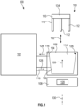
- FIG. 1 illustrates an example of a furnace system 100 that includes a metal furnace 102 and a pump system 104 according to various embodiments.
- the metal furnace 102 may heat and contain a source of molten material, such as molten metal (e.g., molten aluminum).
- the metal furnace 102 may be various types of metal furnaces including, but not limited to, a sidewell melting furnace, a dual chamber furnace, etc. Molten metal from the metal furnace 102 may be used to produce a metal ingot through various casting techniques.
- the pump system 104 includes a tank 106, a magnetic stirrer 108, and a mixer assembly 110.
- the tank 106 includes a tank chamber 114 that is in fluid communication with the metal furnace 102 by an inlet conduit 116 and an outlet conduit 118 such that molten material may be supplied to the tank 106 via the inlet conduit 116 and removed from the tank 106 via the outlet conduit 118.
- an inlet 122 of the tank chamber 114 is at a vertical position that is below a vertical position of an outlet 124 of the tank chamber 114 such that molten material is pumped in an upwards direction within the tank chamber 114.
- the tank chamber 114 has a chamber wall 126.
- a transverse dimension, such as a diameter, of the chamber wall 126 proximate to an inlet 122 of the tank chamber 114 is different from the transverse dimension of the chamber wall 126 proximate to an outlet 124 of the tank chamber 114.
- the transverse dimension of the chamber wall 126 proximate to the inlet 122 is less than the transverse dimension of the chamber wall 126 proximate to the outlet 124.
- the tank chamber 114 having at least two different transverse dimensions may guide and/or improve movement of the molten material through the tank chamber 114.
- the chamber wall 126 having at least two different transverse dimensions may also shape an upper surface of the molten material within the tank chamber 114 (e.g., to have a conical shape) at certain pumping speeds to form a collection point for dross and facilitate removal of dross.
- the chamber wall 126 shapes the molten material such that a collection point is formed in a top surface of the molten material within the tank chamber 114 for dross and facilitate removal of dross.
- the collection point may facilitate removal of dross with a dross removal device (such as, but not limited to, a robotic arm, an Archimedes screw type assembly, etc.).
- the chamber wall 126 may also provide better scrap submergence within the tank chamber 114 because the chamber wall 126 may generate a vortex in the molten material, which may lead to scrap being submerged within the melt and not on the melt surface.
- the chamber wall 126 may also promote mixing during mixing processes (e.g., salt injection) because the vortex generated by the chamber wall 126 may submerge the added material (e.g., salt) below the melt surface, which may minimize or reduce salt loss entrapment on the melt surface and lead to lower salt consumption.
- the chamber wall 126 may also optionally allow for pumping of the molten material without requiring drain plugs near the drain hole due to the improved mixing in the molten material, thereby reducing the safety hazard otherwise associated with drain plugs.
- the profile of the chamber wall 126 is illustrated as linear in FIG. 1 , it need not be in other examples, and the particular profile of the chamber wall 126 should not be considered limiting.
- the geometry of the chamber wall 126 may be selected to improve flow of the molten metal within the tank chamber 114 and/or to ensure the molten metal climbs up the chamber wall 126 to be discharged out the outlet 124.
- the magnetic stirrer 108 includes a permanent magnet 120 that is rotatable about an axis such that the permanent magnet 120 generates a moving magnetic field.
- the permanent magnet 120 is rotatable about a vertical axis 130 of the tank chamber 114, although in other examples the permanent magnet 120 may be rotatable about any axis as desired. While a single permanent magnet 120 is illustrated, in other examples, the magnetic stirrer 108 may include a plurality of permanent magnets 120 that are each rotatable about an axis.
- the tank 106 is supported above the magnetic stirrer 108 such that the moving magnetic field generated by the rotating permanent magnet 120 induces movement in the molten material in the tank chamber 114, thereby pumping the molten material through the tank chamber 114 along a flow path (represented by arrows 128) and recirculating the molten material back to the metal furnace 102.
- the mixer assembly 110 includes at least one mixer 112 and is movable (represented by arrow 132) between a lowered position and a raised position.
- the at least one mixer 112 in the lowered position, may be positioned at least partially within the tank chamber 114 and/or at least partially within the molten metal within the tank chamber 114, and, in the raised position, the at least one mixer 112 may be positioned above the molten metal within the tank chamber 114 and/or outside of the tank chamber 114.
- the mixer assembly 110 may be in the raised position or the lowered position depending on a process of the pump system 104.
- the mixer assembly 110 may be in the raised position for certain pumping and/or dross collection processes and may be in the lowered position for certain scrap addition or mixing processes (e.g., salt injection).
- the mixer assembly 110 may include any number of mixers 112 as desired, so while three mixers 112 are illustrated in FIG. 1 , the number of mixers 112 should not be considered limiting.
- the mixers 112 may be interconnected through or integrally formed with a common base 134 such that the mixers 112 are movable together between the raised position and the lowered position.
- each mixer 112 may be independently movable relative to another mixer 112 between the raised position and the lowered positions.
- the mixers 112 may be at various angles relative to the vertical axis 130 of the tank chamber 114. In various aspects, the angle of the mixers 112 relative to the vertical axis 130 may at least partially control a rotational flow characteristic of the molten material within the tank chamber 114. In the example of FIG. 1 , the mixers 112 are substantially parallel to the vertical axis 130, although they need not be substantially parallel to the vertical axis 130 in other examples. As some non-limiting examples, in other cases, one or more of the mixers 112 may be at an angle of about 15°, about 30°, about 45°, about 60°, etc. relative to the vertical axis 130.
- the angle of one mixer 112 relative to the vertical axis 130 may be the same as or different from the angle of another mixer 112 relative to the vertical axis 130.
- the mixers 112 may be fixed at their respective angles relative to the vertical axis 130; however, in other examples, one or more mixers 112 may be adjustable such that the mixers 112 can be positioned at an angle relative to the vertical axis 130 as desired.
- each mixer 112 may have a supply passageway that may be used to add various injectable materials (e.g., salt) into the molten material in the tank chamber 114.
- various injectable materials e.g., salt
- the mixers 112 with the supply passageway may allow for the injectable material to be added below the melt surface of the molten material, which may minimize salt loss entrapment on the metal surface and lead to lower salt consumption.
- each mixer 112 may have one or more fins along an edge of the mixer 112 to generate rotational flow within the molten material.
- the mixers 112 in the lowered position may maintain their general position within the tank chamber 114 (e.g., they may be stationary within the tank chamber 114). As discussed in greater detail below, molten material flowing within the tank chamber 114 (e.g., by the magnetic stirrer 108) may flow around the mixers 112, and the flow of the molten material around the mixers 112 may generate additional rotational flow within the molten metal.
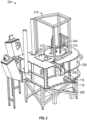
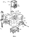
- FIGS. 2-7 illustrate another example of a pump system 204 according to various embodiments.
- the pump system 204 is substantially similar to the pump system 104 and includes a tank 206, a magnetic stirrer 208, and a mixer assembly 210.
- the magnetic stirrer 208 is substantially similar to the magnetic stirrer and includes a rotatable permanent magnet (not visible in the views illustrated).
- a refractory material 236 may support the tank 206, and various covering materials 238 (e.g., steel plates or other suitable material) may enclose the tank 206 and refractory material 236.
- various covering materials 238 e.g., steel plates or other suitable material
- the profile of a chamber wall 226 of the tank chamber 214 is different from the profile of the chamber wall 126 of FIG. 1 and is non-linear between the portion of the chamber wall 226 proximate to an inlet 222 and the portion of the chamber wall 226 proximate to an outlet 224.
- a transverse dimension of the tank chamber 214 proximate to the inlet 222 is less than the transverse dimension of the tank chamber 214 proximate to the outlet 224.
- the tank chamber 214 with the reduced transverse dimension proximate to the inlet 222 may promote and/or improve the flow of the molten material through the tank chamber 214 from the inlet 222 to the outlet 224.
- the geometry of the chamber wall of the tank chamber 214 may be selected to improve flow of the molten metal within the tank chamber 214 and/or to ensure the molten metal climbs up the chamber wall to be discharged out the outlet.
- the geometry of the chamber wall of the tank chamber 214 may generate a vortex in the molten material, which may improve scrap submergence inside the melt, improve the flow of molten metal through the tank (e.g., improved pumping), improve mixing of the molten material within the tank chamber (and reducing metal solidification within the tank chamber), and/or improve mixing of scrap and/or other injectable material in the melt.
- the tank 206 also includes a supplemental chamber 240 that is in fluid communication with the outlet 224 of the tank chamber 214 and a supplemental inlet 242 of the tank chamber 214.
- a supplemental chamber 240 that is in fluid communication with the outlet 224 of the tank chamber 214 and a supplemental inlet 242 of the tank chamber 214.
- at least some of the molten material exiting the tank chamber 214 may be diverted to the supplemental chamber 240 and recirculated back into the tank chamber 214 via the supplemental inlet 242.
- the supplemental chamber 240 may be omitted.
- the mixer assembly 210 includes three mixers 212.
- Each of the mixers 212 includes a body 246 that is optionally supported on a support 252.
- the body 246 is movable along the support 252 such that the mixer 212 is movable between the lowered position and the raised position, although in other examples, the body 246 is fixed relative to the support 252 (i.e., not movable).
- the body 246 is fixed relative to the support 252.
- the support 252 may be omitted and various other suitable devices or mechanisms may be utilized to support and/or position the body 246 as desired.
- the body 246 has a first edge 248 and a second edge 250 opposite from the first edge 248.
- the first edge 248 and the second edge 250 may extend along a length of the body 246.
- the second edge 250 may include one or more fins 256.
- the fins 256 may be integrally formed with the body 246 or may be separate components that are coupled to the body 246 through various suitable mechanisms.
- the second edge 250 includes seven fins 256, although the number of fins 256 should not be considered limiting.
- the shape, profile, or pattern of the fins 256 should not be considered limiting.
- rotational flow generated by the fins 256 may be controlled by controlling one or more of the number of fins 256 on the mixer 212, the profile or pattern of the fins 256, the number of mixers 212 with the mixer assembly 210, the angle of the mixer 212 relative to the vertical axis of the tank chamber 214, the orientation of the second edge 250 with the fins 256 relative to the vertical axis (e.g., the second edge 250 faces radially inwards, radially outwards, in a clockwise circumferential direction, in a counter-clockwise circumferential direction, etc.), or other features of the mixer assembly 210.
- each mixer 212 may include a supply passageway 258 that extends at least partially through the body 246 and is in fluid communication with one or more openings 260 that are defined by the body 246.
- the openings 260 may be defined in edges or sides of the body 246 that are not a leading edge or side in the flow of molten material (e.g., in a trailing edge of the body 246).
- the openings 260 are defined in the second edge 250 of the body 246.
- the number, shape, location, and profile of the openings 260 and/or the supply passageway 258 should not be considered limiting.
- each opening 260 may have a dedicated supply passageway 258 rather than having a common supply passageway 258 for the openings 260.
- the supply passageway 258 may be in fluid communication with an injectable material source 262 such that an injectable material, including but not limited to salt, may be selectively supplied into the molten material via the supply passageway 258 and the openings 260.
- all of the mixers 212 may include the supply passageway 258 and the openings 260 or a subset of the mixers 212 may include the supply passageway 258 and the openings 260.
- the injectable material may be supplied to the molten material when the mixers 212 are in the lowered position.
- the mixer assembly 210 also includes a dross removal device 244.
- the dross removal device 244 may be any suitable device or mechanism for removing dross from the molten material in the tank chamber 214.
- the dross removal device 244 is a robotic arm; however, in other examples, the dross removal device 244 may be any other suitable device.
- a non-limiting example of another dross removal device 244 includes an Archimedes screw type assembly.
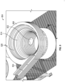
- FIGS. 8 and 9 illustrate another example of a portion of a pump system 804 with a tank 806 and a magnetic stirrer 808. Although not illustrated, a mixer assembly similar to the mixer assembly 110 or the mixer assembly 210 may be utilized with the pump system 804.
- the tank 806 is substantially similar to the tank 206 except that the supplemental chamber 240 is omitted.
- the profile of a chamber wall 826 of a tank chamber 814 of the tank 806 is non-linear between the portion of the chamber wall 826 proximate to an inlet 822 and the portion of the chamber wall 826 proximate to an outlet 824.
- a transverse dimension of the tank chamber 814 proximate to the inlet 822 is less than the transverse dimension of the tank chamber 814 proximate to the outlet 824 such that the chamber wall 826 narrows from the top of the tank chamber 814 toward the bottom of the tank chamber 814.
- the magnetic stirrer 808 of the pump system 804 includes one or more permanent magnets rotatable about an axis, and the magnetic stirrer 808 is positioned below the tank 806 such that a moving magnetic field generated by the rotating permanent magnet induces movement in the molten material in the tank chamber 814 of the tank 806.
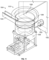
- FIGS. 10 and 11 illustrate another example of a pump system 1004 with a tank 1006, magnetic stirrer 1008, and mixer assembly 1010 (omitted from FIG. 11 ).
- the pump system 1004 is in fluid communication with a furnace 1002.
- the tank 1006 is similar to the previously mentioned tanks and includes a chamber wall 1026 having a profile that is non-linear between the portion of the chamber wall 1026 proximate to an inlet 1022 and the portion of the chamber wall 1026 proximate to an outlet 1024.
- a transverse dimension of the tank chamber 1014 proximate to the inlet 1022 is less than the transverse dimension of the tank chamber 1014 proximate to the outlet 1024 such that the chamber wall 1026 narrows from the top of the tank chamber 1014 toward the bottom of the tank chamber 1014.
- the mixer assembly 1010 includes three mixers 1012 and is movable between the raised position and the lowered position such that the mixers 1012 are at least partially within the molten material.
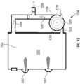
- FIG. 12 illustrates an example of a pump system 1204 with a sidewell melting furnace 1202 that includes a main furnace chamber 1203.
- One or more burners 1207 or other suitable heating elements are provided to produce a molten condition.
- the pump system 1204 is substantially similar to the previously discussed pump systems and includes a tank 1206 having a chamber wall with a profile that is non-linear between an inlet 1222 and the an outlet 1224.
- a transverse dimension of the tank chamber proximate to the inlet 1222 is less than the transverse dimension of the tank chamber proximate to the outlet 1224 such that the chamber wall narrows from the top of the tank chamber toward the bottom of the tank chamber.
- the pump system 1204 also includes a magnetic stirrer and a mixer assembly.
- a flow of molten material is represented by arrows 1205, and the flow path may be from the main furnace chamber 1203, to the tank 1206, and either back to the main furnace chamber 1203 or for further processing.
- various materials such as metal scrap (represented by arrow 1211) and/or injectable materials (represented by arrow 1209) may be added during the melting process.
- the sidewell melting furnace 1202 with the pump system 1204 may promote better submergence of the scrap 1211 because of the vortex generated in the tank 1206, which may lead to scrap submerged inside the melt and not on the melt surface.
- Salt or other injectable materials 1209 are similarly better submerged below the melt surface and mixed, which may minimize salt loss entrapment on the melt surface and lead to lower salt consumption. Drain plugs may optionally be omitted because of the improved mixing and pumping of molten material with the tank 1206.
- FIGS. 13 and 14 illustrate an example of the pump system 1204 with a dual chamber furnace 1302 that includes a scrap chamber 1313 and a heating chamber 1315.
- Metal scrap 1317 (see FIG. 14 ) may be introduced into the scrap chamber 1313 (in addition to the metal scrap 1211).
- a flow of molten material is represented by arrows 1305, and the flow path may be from the scrap chamber 1313, to the heating chamber 1315, to the tank 1206, and back to the scrap chamber 1313.
- the dual chamber furnace 1302 with the pump system 1204 may promote better submergence of the scrap 1211 and/or other injectable materials 1209.
- the dual chamber furnace 1302 may also be more easily cleaned compared to existing dual chamber furnaces because the pump system 1204 may be an open system and components are more easily accessible.
- a method of processing molten material with the pump system 104 is also provided. While reference will be made to the pump system 104, it will be appreciated that the following description is equally applicable to the pump system 204 and the pump system 804, or other pump systems, unless expressly noted otherwise.
- the method may include receiving the molten material from the furnace 102 in the tank chamber 114 of the tank 106.
- Receiving the molten material may optionally include drawing the molten material from the furnace 102, through the inlet conduit 116 and the inlet 122, and into the tank chamber 114 by rotating the permanent magnet 120 of the magnetic stirrer 108 such that a rotational or mixing flow is generated within the tank chamber 114.
- controlling the flow of molten material includes controlling the flow of the molten material through the tank chamber 114 from the inlet 122 to the outlet 124.
- controlling the flow of molten material may include, but is not limited to, controlling one or more of a rotational speed of the permanent magnet 120, an axis of rotation of the permanent magnet, a number of permanent magnets, and/or a profile of the chamber wall 126 of the tank chamber 114.
- the profile of the chamber wall 126 is controlled such that the transverse dimension of the tank chamber 114 proximate to the inlet 122 is less than the transverse dimension of the tank chamber 114 proximate to the outlet 124.
- the method includes controlling the flow of the molten material by controlling the magnetic stirrer 108 such that a collection point is formed in a top surface of the molten material within the tank chamber 114 for dross and facilitate removal of dross.
- the method may include using a dross removal device to remove the dross from the molten material before it is pumped out the outlet 124.
- the method may include lowering one or more mixers 112 of the mixer assembly 110 from the raised position to the lowered position such that the mixers 112 are at least partially within the molten material.
- the method includes substantially maintaining a position of the mixers 112 relative to the tank chamber 114 (e.g., the mixers 112 are stationary within the tank chamber 114).
- an edge of a body of each mixer 112 may include one or more fins, and the one or more fins positioned within the molten material may generate turbulence and/or a supplemental mixing flow (in addition to the flow generated by the magnetic stirrer 108) within the molten material.
- the method may include controlling the supplemental mixing flow generated by the fins of the mixers 112 by controlling one or more of the number of fins on the mixer 112, the profile or pattern of the fins, the number of mixers 112 with the mixer assembly 110, the angle of the mixer 112 relative to the vertical axis 130 of the tank chamber 114, or the orientation of the edge with the fins 1 relative to the vertical axis 130, or other features of the mixer assembly 110.
- the method may include adding scrap material to the molten material in the tank chamber 114 while the mixers 112 are in the lowered position.
- the method may include injecting an injectable material (such as, but not limited to, salt) into the molten material while the mixers 112 are in the lowered position.
- injecting the injectable material may include supplying the injectable material to the supply passageway defined in the body of each mixer 112 and directing the injectable material through the supply passageway and out the one or more openings defined in the body of each mixer 112.
- injecting the injectable material may include controlling at least one of the type of injectable material injected into the molten material, a flow or supply rate of the injectable material, a number of openings defined in the body of each mixer 112, or other features of the mixer assembly 110.
- the method may include raising the mixer assembly 110 from the lowered position to the raised position after adding the scrap material and/or after injecting the injectable material.
Landscapes
- Engineering & Computer Science (AREA)
- Mechanical Engineering (AREA)
- General Engineering & Computer Science (AREA)
- Waste-Gas Treatment And Other Accessory Devices For Furnaces (AREA)
- Reciprocating Pumps (AREA)
- Vertical, Hearth, Or Arc Furnaces (AREA)
- Jet Pumps And Other Pumps (AREA)
- Manufacture And Refinement Of Metals (AREA)
- Mixers With Rotating Receptacles And Mixers With Vibration Mechanisms (AREA)
- Details Of Reciprocating Pumps (AREA)
- Physical Or Chemical Processes And Apparatus (AREA)
- Structures Of Non-Positive Displacement Pumps (AREA)
Claims (6)
- Pumpsystem (204, 804, 1004, 1204) für einen Metallofen (102), wobei das Pumpsystem (204, 804, 1004, 1204) umfasst:einen Behälter (206, 806, 1006, 1206), umfassend eine Behälterkammer (214, 814, 1014), welche dazu eingerichtet ist, ein geschmolzenes Material aufzunehmen; undeine magnetische Rührvorrichtung (208, 808, 1008), welche einen rotierenden Permanentmagneten (120) umfasst, wobei der Behälter (206, 806, 1006, 1206) oberhalb der magnetischen Rührvorrichtung (208, 808, 1008) positioniert ist und derart, dass die magnetische Rührvorrichtung (208, 808, 1008) außerhalb der Behälterkammer (214, 814, 1014) ist, und wobei die magnetische Rührvorrichtung (208, 808, 1008) dazu eingerichtet ist, ein sich bewegendes Magnetfeld in dem geschmolzenen Material in der Behälterkammer (214, 814, 1014) zu erzeugen, um eine Bewegung in dem geschmolzenen Material zu induzieren,einen Einlass (222, 822, 1022, 1222), welcher in Fluidkommunikation mit der Behälterkammer (214, 814, 1014) steht und einen Strömungspfad zu der Behälterkammer (214, 814, 1014) für geschmolzenes Material definiert, welches in die Behälterkammer (214, 814, 1014) eintritt; undeinen Auslass (224, 824, 1024, 1224), welcher in Fluidkommunikation mit der Behälterkammer (214, 814, 1014) steht und einen Strömungspfad von der Behälterkammer (214, 814, 1014) für geschmolzenes Material definiert, welches aus der Behälterkammer (214, 814, 1014) austritt,wobei sich eine transversale Abmessung der Behälterkammer (214, 814, 1014) in der Nähe des Einlasses (222, 822, 1022, 1222) von der transversalen Abmessung der Behälterkammer (214, 814, 1014) in der Nähe des Auslasses unterscheidet, wobei die transversale Abmessung der Behälterkammer (214, 814, 1014) die Abmessung über einen weitesten Abschnitt der Behälterkammer (214, 814, 1014) ist,wobei eine Fläche der Behälterkammer (214, 814, 1014) einen nicht-lineare Krümmung zwischen dem Einlass (222, 822, 1022, 1222) und dem Auslass (224, 824, 1024, 1224) umfasst,dadurch gekennzeichnet, dass
das Pumpsystem ferner eine Mischvorrichtung (112, 212, 1012) umfasst, welche selektiv innerhalb der Behälterkammer positionierbar und aus dieser entfernbar ist,wobei die Mischvorrichtung (212, 1012) einen Körper (246) umfasst, wobei der Körper (246) eine oder mehrere Finnen (256) entlang eines Randes des Körpers (246) umfasst,wobei die Mischvorrichtung (112, 212, 1012) zwischen einer abgesenkten Position und einer angehobenen Position bewegbar ist, wobei, in der abgesenkten Position, die Mischvorrichtung wenigstens teilweise innerhalb der Behälterkammer (114, 214, 814, 1014) und/oder wenigstens teilweise innerhalb des geschmolzenen Materials innerhalb der Behälterkammer (114, 214, 814, 1014) positioniert ist, und, in der angehobenen Position, die Mischvorrichtung oberhalb des geschmolzenen Materials innerhalb der Behälterkammer (114, 214, 814, 1014) und/oder außerhalb der Behälterkammer (114, 214, 814, 1014) positioniert ist. - Pumpsystem nach Anspruch 1,wobei eine vertikale Position des Einlasses (222, 822, 1022, 1222) niedriger als eine vertikale Position des Auslasses (224, 824, 1024, 1224) ist, oderwobei die transversale Abmessung der Behälterkammer (214, 814, 1014) in der Nähe des Einlasses (222, 822, 1022, 1222) geringer als die transversale Abmessung der Behälterkammer (214, 814, 1014) in der Nähe des Auslasses (224, 824, 1024, 1224) ist.
- Pumpsystem (104, 204, 804, 1004, 1204) nach Anspruch 1, wobei der Körper (246) einen Zuführdurchgang definiert, welcher wenigstens eine Öffnung entlang eines vertikalen Randes (250) des Körpers (246) aufweist, wobei die Mischvorrichtung dazu eingerichtet ist, selektiv ein injizierbares Material über den Zuführdurchgang und die wenigstens eine Öffnung in die Behälterkammer zuzuführen.
- Verfahren, umfassend:Aufnehmen, von einem Ofen (102), von geschmolzenem Material in einer Behälterkammer (114, 214, 814, 1014) eines Behälters (106, 206, 806, 1006, 1206) eines Pumpsystems (104, 204, 804, 1004, 1204) nach einem der vorhergehenden Ansprüche;Erzeugen einer Mischströmung in dem geschmolzenen Material in der Behälterkammer (114, 214, 814, 1014),wobei das Erzeugen der Mischströmung umfasst:Rotieren eines Permanentmagneten (120) einer magnetischen Rührvorrichtung (108, 208, 808, 1008) des Pumpsystems, um ein sich bewegendes Magnetfeld in dem geschmolzenen Material in der Behälterkammer (114, 214, 814, 1014) zu erzeugen; undSteuern, durch die magnetische Rührvorrichtung (108, 208, 808, 1008), des sich bewegenden Magnetfelds, um eine Bewegung in dem geschmolzenen Material zu induzieren, wobei der Behälter (106, 206, 806, 1006, 1206) oberhalb der magnetischen Rührvorrichtung derart positioniert ist, dass die magnetische Rührvorrichtung außerhalb der Behälterkammer (114, 214, 814, 1014) ist; undAbgeben des geschmolzenen Materials aus dem Behälter.
- Verfahren nach Anspruch 4, ferner umfassend Entfernen von Schlacke aus dem geschmolzenen Material in der Behälterkammer (114, 214, 814, 1014), während die Mischströmung in dem geschmolzenen Material erzeugt wird, oder
wobei die Mischströmung eine sekundäre Mischströmung ist und wobei das Verfahren ferner umfasst:Erzeugen einer primären Mischströmung in dem geschmolzenen Material durch Absenken einer Mischvorrichtung (112, 212, 1012) in die Behälterkammer (114, 214, 814, 1014) und wenigstens teilweise in das geschmolzene Material, wobei die Mischvorrichtung einen Körper (246) umfasst, wobei der Körper (246) einen Rand umfasst, welcher sich entlang einer Länge der Mischvorrichtung erstreckt, wobei der Rand eine oder mehrere Finnen umfasst,wobei das Verfahren vorzugsweise ferner ein Hinzufügen von Schrottmaterial in die Behälterkammer (114, 214, 814, 1014) während des Erzeugens der primären Mischströmung umfasst. - Verfahren nach Anspruch 4, ferner umfassend Injizieren eines injizierbaren Materials in das geschmolzene Material, während die Mischströmung erzeugt wird, durch:Absenken einer Mischvorrichtung (112, 212, 1012) in die Behälterkammer (114, 214, 814, 1014) und wenigstens teilweise in das geschmolzene Material, wobei die Mischvorrichtung (112, 212, 1012) einen Körper (246) umfasst, wobei der Körper (246) einen Zuführdurchgang (258) umfasst, welcher sich wenigstens teilweise durch den Körper (246) erstreckt und wenigstens eine Öffnung (260) umfasst, welche in einem Rand (250) des Körpers (246) definiert ist; undInjizieren des injizierbaren Materials durch den Zuführdurchgang (258) aus der wenigstens einen Öffnung (260) heraus und in das geschmolzene Material.
Priority Applications (1)
| Application Number | Priority Date | Filing Date | Title |
|---|---|---|---|
| EP24223834.3A EP4520457A3 (de) | 2020-02-25 | 2021-02-16 | Mehrzweckpumpensystem für einen metallofen und zugehöriges verfahren |
Applications Claiming Priority (2)
| Application Number | Priority Date | Filing Date | Title |
|---|---|---|---|
| US202062981282P | 2020-02-25 | 2020-02-25 | |
| PCT/US2021/070157 WO2021174241A1 (en) | 2020-02-25 | 2021-02-16 | Multi-purpose pump system for a metal furnace and related methods |
Related Child Applications (1)
| Application Number | Title | Priority Date | Filing Date |
|---|---|---|---|
| EP24223834.3A Division EP4520457A3 (de) | 2020-02-25 | 2021-02-16 | Mehrzweckpumpensystem für einen metallofen und zugehöriges verfahren |
Publications (2)
| Publication Number | Publication Date |
|---|---|
| EP4111120A1 EP4111120A1 (de) | 2023-01-04 |
| EP4111120B1 true EP4111120B1 (de) | 2025-01-01 |
Family
ID=75362661
Family Applications (2)
| Application Number | Title | Priority Date | Filing Date |
|---|---|---|---|
| EP24223834.3A Withdrawn EP4520457A3 (de) | 2020-02-25 | 2021-02-16 | Mehrzweckpumpensystem für einen metallofen und zugehöriges verfahren |
| EP21716250.2A Active EP4111120B1 (de) | 2020-02-25 | 2021-02-16 | Mehrzweckpumpensystem für einen metallofen und zugehörige verfahren |
Family Applications Before (1)
| Application Number | Title | Priority Date | Filing Date |
|---|---|---|---|
| EP24223834.3A Withdrawn EP4520457A3 (de) | 2020-02-25 | 2021-02-16 | Mehrzweckpumpensystem für einen metallofen und zugehöriges verfahren |
Country Status (9)
| Country | Link |
|---|---|
| US (1) | US20230147586A1 (de) |
| EP (2) | EP4520457A3 (de) |
| JP (1) | JP7454690B2 (de) |
| KR (1) | KR20220129057A (de) |
| CN (2) | CN119641648A (de) |
| BR (1) | BR112022015089A2 (de) |
| CA (1) | CA3169616A1 (de) |
| MX (1) | MX2022010158A (de) |
| WO (1) | WO2021174241A1 (de) |
Families Citing this family (2)
| Publication number | Priority date | Publication date | Assignee | Title |
|---|---|---|---|---|
| WO2026069257A1 (fr) * | 2024-09-30 | 2026-04-02 | Lethiguel | Installation de four pour métal liquide, avec chauffage électrique et brassage amélioré |
| CN119334124B (zh) * | 2024-12-19 | 2025-03-18 | 定襄清瑞新材料科技有限公司 | 一种用于铁合金矿热炉的全自动配料系统及其使用方法 |
Family Cites Families (25)
| Publication number | Priority date | Publication date | Assignee | Title |
|---|---|---|---|---|
| US5531425A (en) * | 1983-06-06 | 1996-07-02 | Alcan Aluminum Corporation | Apparatus for continuously preparing castable metal matrix composite material |
| BE1004002A6 (fr) * | 1990-04-04 | 1992-09-08 | Centre Rech Metallurgique | Procede et dispositif pour l'introduction d'elements de renforcement dans un bain de metal fondu. |
| JPH05156378A (ja) * | 1991-10-07 | 1993-06-22 | Miyamoto Kogyosho:Kk | アルミニウム廃材の溶解方法と溶解炉 |
| JPH10160350A (ja) * | 1996-12-02 | 1998-06-19 | Tokyo Gas Co Ltd | 金属切り粉溶解炉 |
| JP3879794B2 (ja) * | 1998-03-19 | 2007-02-14 | 東京窯業株式会社 | ガス吹きプラグ |
| RU2197540C2 (ru) * | 2001-04-24 | 2003-01-27 | Хлопонин Виктор Николаевич | Способ перемешивания стали в ковше |
| JP2006017348A (ja) * | 2004-06-30 | 2006-01-19 | Kenzo Takahashi | 攪拌装置付溶解炉及び攪拌装置 |
| JP2006349293A (ja) * | 2005-06-17 | 2006-12-28 | Kenzo Takahashi | 攪拌装置付溶解炉及び溶解炉用攪拌装置 |
| JP2008196807A (ja) * | 2007-02-14 | 2008-08-28 | Kenzo Takahashi | 溶解炉用原料押込装置及びそれを組み込んだ溶解炉システム |
| JP5163615B2 (ja) * | 2008-10-29 | 2013-03-13 | トヨタ自動車株式会社 | 撹拌装置、溶解装置および溶解方法 |
| JP4995234B2 (ja) * | 2008-12-26 | 2012-08-08 | 株式会社ヂーマグ | 非鉄金属溶湯ポンプ及びそれを用いた非鉄金属溶解炉 |
| WO2010131742A1 (ja) * | 2009-05-15 | 2010-11-18 | 株式会社Istc | 電気炉製鋼法 |
| US8524146B2 (en) * | 2009-08-07 | 2013-09-03 | Paul V. Cooper | Rotary degassers and components therefor |
| CN201787806U (zh) * | 2010-07-27 | 2011-04-06 | 游述怀 | 竖式双室再生熔炼炉 |
| CN202547396U (zh) * | 2012-04-13 | 2012-11-21 | 金川集团有限公司 | 一种冶金复合式喷枪 |
| HUE033155T2 (en) * | 2013-03-11 | 2017-11-28 | Novelis Inc | Magnetic pump station |
| CN104745843B (zh) * | 2013-12-31 | 2017-04-19 | 北京有色金属研究总院 | 一种自动化合金流变浆料制备及流变成型的装置和方法 |
| PL3086069T3 (pl) * | 2015-04-23 | 2019-11-29 | Digimet 2013 Sl | Piec do topienia i obróbki metalu i odpadów metalu oraz jego sposób |
| MX2018003009A (es) * | 2015-09-10 | 2018-06-27 | Andritz Metals Inc | Horno de retencion de aluminio por inmersión eléctrica con medios de circulacion y metodo relacionado. |
| JP6042519B1 (ja) * | 2015-11-05 | 2016-12-14 | 高橋 謙三 | 溶湯搬送ポンプ及び溶湯搬送システム |
| CN105716420A (zh) * | 2016-03-08 | 2016-06-29 | 焦伟丽 | 一种用于制备新型铝材的搅拌式反应釜 |
| KR101966205B1 (ko) * | 2017-08-28 | 2019-04-05 | (주)디에스리퀴드 | 알루미늄 용해로 |
| KR101966206B1 (ko) * | 2017-08-28 | 2019-04-05 | (주)디에스리퀴드 | 알루미늄 용해로 |
| KR102079388B1 (ko) * | 2019-09-27 | 2020-02-19 | 박승필 | 연속식 알루미늄 복합 용해로 |
| CN110813176A (zh) * | 2019-12-19 | 2020-02-21 | 安徽顶艺机车部件智造有限公司 | 一种锌液搅拌罐 |
-
2021
- 2021-02-16 WO PCT/US2021/070157 patent/WO2021174241A1/en not_active Ceased
- 2021-02-16 BR BR112022015089A patent/BR112022015089A2/pt not_active Application Discontinuation
- 2021-02-16 CA CA3169616A patent/CA3169616A1/en active Pending
- 2021-02-16 EP EP24223834.3A patent/EP4520457A3/de not_active Withdrawn
- 2021-02-16 KR KR1020227028684A patent/KR20220129057A/ko active Pending
- 2021-02-16 MX MX2022010158A patent/MX2022010158A/es unknown
- 2021-02-16 CN CN202411818640.3A patent/CN119641648A/zh active Pending
- 2021-02-16 JP JP2022550136A patent/JP7454690B2/ja active Active
- 2021-02-16 EP EP21716250.2A patent/EP4111120B1/de active Active
- 2021-02-16 CN CN202180016661.1A patent/CN115151775B/zh active Active
- 2021-02-16 US US17/904,240 patent/US20230147586A1/en not_active Abandoned
Also Published As
| Publication number | Publication date |
|---|---|
| CA3169616A1 (en) | 2021-09-02 |
| CN115151775A (zh) | 2022-10-04 |
| KR20220129057A (ko) | 2022-09-22 |
| US20230147586A1 (en) | 2023-05-11 |
| WO2021174241A1 (en) | 2021-09-02 |
| CN119641648A (zh) | 2025-03-18 |
| EP4520457A3 (de) | 2025-05-14 |
| CN115151775B (zh) | 2024-12-24 |
| JP2023515106A (ja) | 2023-04-12 |
| BR112022015089A2 (pt) | 2022-09-20 |
| MX2022010158A (es) | 2022-09-12 |
| EP4520457A2 (de) | 2025-03-12 |
| JP7454690B2 (ja) | 2024-03-22 |
| EP4111120A1 (de) | 2023-01-04 |
Similar Documents
| Publication | Publication Date | Title |
|---|---|---|
| US10215495B2 (en) | Metallurgical apparatus | |
| CN111347018B (zh) | 非接触式熔融金属流动控制 | |
| KR102134809B1 (ko) | 용융 금속 스크랩 침강 장치 | |
| EP4111120B1 (de) | Mehrzweckpumpensystem für einen metallofen und zugehörige verfahren | |
| US9074601B1 (en) | Pump for pumping molten metal with reduced dross formation in a bath of molten metal | |
| CN104121787B (zh) | 熔融金属循环驱动装置及具有其的熔炉 | |
| CN102149832B (zh) | 熔液净化装置 | |
| CN102223966A (zh) | 搅拌装置、熔化装置以及熔化方法 | |
| KR101235769B1 (ko) | 고주파 유도가열을 이용한 동 다이캐스팅용 용탕 공급장치 | |
| EP4006471A1 (de) | Metallschmelzvorrichtung, siebplatte zum schmelzen von metall und verfahren zum schmelzen von metall | |
| JP2023535244A (ja) | スクラップ浸漬装置及び関連プロセス | |
| US20180216890A1 (en) | Metallurgical apparatus | |
| US11874062B2 (en) | Repositionable molten metal pump | |
| JP2003105455A (ja) | 金属溶湯処理装置 | |
| JP2009056475A (ja) | コンビネーション溶解システム | |
| JP2020069484A (ja) | 保持炉 | |
| WO2026064384A1 (en) | Permanent magnet filter priming and degassing | |
| KR20250002941A (ko) | 틸팅 기능을 겸비한 회전용해로 | |
| WO2025101894A1 (en) | Scrap submergence device with angled blades | |
| KR101247946B1 (ko) | 동 다이캐스팅용 용탕 주입장치 | |
| GB2536185A (en) | Method and apparatus for submerging materials into a molten material bath |
Legal Events
| Date | Code | Title | Description |
|---|---|---|---|
| STAA | Information on the status of an ep patent application or granted ep patent |
Free format text: STATUS: UNKNOWN |
|
| STAA | Information on the status of an ep patent application or granted ep patent |
Free format text: STATUS: THE INTERNATIONAL PUBLICATION HAS BEEN MADE |
|
| PUAI | Public reference made under article 153(3) epc to a published international application that has entered the european phase |
Free format text: ORIGINAL CODE: 0009012 |
|
| STAA | Information on the status of an ep patent application or granted ep patent |
Free format text: STATUS: REQUEST FOR EXAMINATION WAS MADE |
|
| 17P | Request for examination filed |
Effective date: 20220914 |
|
| AK | Designated contracting states |
Kind code of ref document: A1 Designated state(s): AL AT BE BG CH CY CZ DE DK EE ES FI FR GB GR HR HU IE IS IT LI LT LU LV MC MK MT NL NO PL PT RO RS SE SI SK SM TR |
|
| DAV | Request for validation of the european patent (deleted) | ||
| DAX | Request for extension of the european patent (deleted) | ||
| STAA | Information on the status of an ep patent application or granted ep patent |
Free format text: STATUS: EXAMINATION IS IN PROGRESS |
|
| 17Q | First examination report despatched |
Effective date: 20230615 |
|
| REG | Reference to a national code |
Ref country code: DE Ref legal event code: R079 Free format text: PREVIOUS MAIN CLASS: F27B0003040000 Ipc: B22D0001000000 Ref document number: 602021024241 Country of ref document: DE |
|
| GRAP | Despatch of communication of intention to grant a patent |
Free format text: ORIGINAL CODE: EPIDOSNIGR1 |
|
| STAA | Information on the status of an ep patent application or granted ep patent |
Free format text: STATUS: GRANT OF PATENT IS INTENDED |
|
| RIC1 | Information provided on ipc code assigned before grant |
Ipc: B22D 35/00 20060101ALI20240614BHEP Ipc: B22D 27/02 20060101ALI20240614BHEP Ipc: F27D 27/00 20100101ALI20240614BHEP Ipc: F27D 3/16 20060101ALI20240614BHEP Ipc: F27D 3/14 20060101ALI20240614BHEP Ipc: F27B 19/04 20060101ALI20240614BHEP Ipc: F27B 3/22 20060101ALI20240614BHEP Ipc: F27B 3/04 20060101ALI20240614BHEP Ipc: B22D 1/00 20060101AFI20240614BHEP |
|
| INTG | Intention to grant announced |
Effective date: 20240722 |
|
| GRAS | Grant fee paid |
Free format text: ORIGINAL CODE: EPIDOSNIGR3 |
|
| GRAA | (expected) grant |
Free format text: ORIGINAL CODE: 0009210 |
|
| STAA | Information on the status of an ep patent application or granted ep patent |
Free format text: STATUS: THE PATENT HAS BEEN GRANTED |
|
| AK | Designated contracting states |
Kind code of ref document: B1 Designated state(s): AL AT BE BG CH CY CZ DE DK EE ES FI FR GB GR HR HU IE IS IT LI LT LU LV MC MK MT NL NO PL PT RO RS SE SI SK SM TR |
|
| REG | Reference to a national code |
Ref country code: GB Ref legal event code: FG4D |
|
| REG | Reference to a national code |
Ref country code: DE Ref legal event code: R096 Ref document number: 602021024241 Country of ref document: DE |
|
| REG | Reference to a national code |
Ref country code: CH Ref legal event code: EP |
|
| REG | Reference to a national code |
Ref country code: IE Ref legal event code: FG4D |
|
| PGFP | Annual fee paid to national office [announced via postgrant information from national office to epo] |
Ref country code: DE Payment date: 20250122 Year of fee payment: 5 |
|
| P01 | Opt-out of the competence of the unified patent court (upc) registered |
Free format text: CASE NUMBER: APP_13503/2025 Effective date: 20250319 |
|
| PGFP | Annual fee paid to national office [announced via postgrant information from national office to epo] |
Ref country code: NO Payment date: 20250219 Year of fee payment: 5 |
|
| PGFP | Annual fee paid to national office [announced via postgrant information from national office to epo] |
Ref country code: CH Payment date: 20250301 Year of fee payment: 5 Ref country code: BE Payment date: 20250218 Year of fee payment: 5 Ref country code: AT Payment date: 20250417 Year of fee payment: 5 |
|
| PGFP | Annual fee paid to national office [announced via postgrant information from national office to epo] |
Ref country code: FR Payment date: 20250218 Year of fee payment: 5 |
|
| REG | Reference to a national code |
Ref country code: LT Ref legal event code: MG9D |
|
| PGFP | Annual fee paid to national office [announced via postgrant information from national office to epo] |
Ref country code: IT Payment date: 20250130 Year of fee payment: 5 Ref country code: GB Payment date: 20250210 Year of fee payment: 5 |
|
| REG | Reference to a national code |
Ref country code: NL Ref legal event code: MP Effective date: 20250101 |
|
| PG25 | Lapsed in a contracting state [announced via postgrant information from national office to epo] |
Ref country code: NL Free format text: LAPSE BECAUSE OF FAILURE TO SUBMIT A TRANSLATION OF THE DESCRIPTION OR TO PAY THE FEE WITHIN THE PRESCRIBED TIME-LIMIT Effective date: 20250101 |
|
| PG25 | Lapsed in a contracting state [announced via postgrant information from national office to epo] |
Ref country code: FI Free format text: LAPSE BECAUSE OF FAILURE TO SUBMIT A TRANSLATION OF THE DESCRIPTION OR TO PAY THE FEE WITHIN THE PRESCRIBED TIME-LIMIT Effective date: 20250101 |
|
| PG25 | Lapsed in a contracting state [announced via postgrant information from national office to epo] |
Ref country code: PL Free format text: LAPSE BECAUSE OF FAILURE TO SUBMIT A TRANSLATION OF THE DESCRIPTION OR TO PAY THE FEE WITHIN THE PRESCRIBED TIME-LIMIT Effective date: 20250101 |
|
| PG25 | Lapsed in a contracting state [announced via postgrant information from national office to epo] |
Ref country code: ES Free format text: LAPSE BECAUSE OF FAILURE TO SUBMIT A TRANSLATION OF THE DESCRIPTION OR TO PAY THE FEE WITHIN THE PRESCRIBED TIME-LIMIT Effective date: 20250101 |
|
| PG25 | Lapsed in a contracting state [announced via postgrant information from national office to epo] |
Ref country code: IS Free format text: LAPSE BECAUSE OF FAILURE TO SUBMIT A TRANSLATION OF THE DESCRIPTION OR TO PAY THE FEE WITHIN THE PRESCRIBED TIME-LIMIT Effective date: 20250501 |
|
| PG25 | Lapsed in a contracting state [announced via postgrant information from national office to epo] |
Ref country code: HR Free format text: LAPSE BECAUSE OF FAILURE TO SUBMIT A TRANSLATION OF THE DESCRIPTION OR TO PAY THE FEE WITHIN THE PRESCRIBED TIME-LIMIT Effective date: 20250101 |
|
| PG25 | Lapsed in a contracting state [announced via postgrant information from national office to epo] |
Ref country code: PT Free format text: LAPSE BECAUSE OF FAILURE TO SUBMIT A TRANSLATION OF THE DESCRIPTION OR TO PAY THE FEE WITHIN THE PRESCRIBED TIME-LIMIT Effective date: 20250502 Ref country code: LV Free format text: LAPSE BECAUSE OF FAILURE TO SUBMIT A TRANSLATION OF THE DESCRIPTION OR TO PAY THE FEE WITHIN THE PRESCRIBED TIME-LIMIT Effective date: 20250101 |
|
| PG25 | Lapsed in a contracting state [announced via postgrant information from national office to epo] |
Ref country code: BG Free format text: LAPSE BECAUSE OF FAILURE TO SUBMIT A TRANSLATION OF THE DESCRIPTION OR TO PAY THE FEE WITHIN THE PRESCRIBED TIME-LIMIT Effective date: 20250101 Ref country code: GR Free format text: LAPSE BECAUSE OF FAILURE TO SUBMIT A TRANSLATION OF THE DESCRIPTION OR TO PAY THE FEE WITHIN THE PRESCRIBED TIME-LIMIT Effective date: 20250402 |
|
| PG25 | Lapsed in a contracting state [announced via postgrant information from national office to epo] |
Ref country code: CZ Free format text: LAPSE BECAUSE OF FAILURE TO SUBMIT A TRANSLATION OF THE DESCRIPTION OR TO PAY THE FEE WITHIN THE PRESCRIBED TIME-LIMIT Effective date: 20250101 |
|
| PG25 | Lapsed in a contracting state [announced via postgrant information from national office to epo] |
Ref country code: SE Free format text: LAPSE BECAUSE OF FAILURE TO SUBMIT A TRANSLATION OF THE DESCRIPTION OR TO PAY THE FEE WITHIN THE PRESCRIBED TIME-LIMIT Effective date: 20250101 |
|
| REG | Reference to a national code |
Ref country code: DE Ref legal event code: R097 Ref document number: 602021024241 Country of ref document: DE |
|
| PG25 | Lapsed in a contracting state [announced via postgrant information from national office to epo] |
Ref country code: SM Free format text: LAPSE BECAUSE OF FAILURE TO SUBMIT A TRANSLATION OF THE DESCRIPTION OR TO PAY THE FEE WITHIN THE PRESCRIBED TIME-LIMIT Effective date: 20250101 |
|
| PG25 | Lapsed in a contracting state [announced via postgrant information from national office to epo] |
Ref country code: DK Free format text: LAPSE BECAUSE OF FAILURE TO SUBMIT A TRANSLATION OF THE DESCRIPTION OR TO PAY THE FEE WITHIN THE PRESCRIBED TIME-LIMIT Effective date: 20250101 |
|
| PG25 | Lapsed in a contracting state [announced via postgrant information from national office to epo] |
Ref country code: MC Free format text: LAPSE BECAUSE OF FAILURE TO SUBMIT A TRANSLATION OF THE DESCRIPTION OR TO PAY THE FEE WITHIN THE PRESCRIBED TIME-LIMIT Effective date: 20250101 |
|
| PG25 | Lapsed in a contracting state [announced via postgrant information from national office to epo] |
Ref country code: LU Free format text: LAPSE BECAUSE OF NON-PAYMENT OF DUE FEES Effective date: 20250216 |
|
| PG25 | Lapsed in a contracting state [announced via postgrant information from national office to epo] |
Ref country code: EE Free format text: LAPSE BECAUSE OF FAILURE TO SUBMIT A TRANSLATION OF THE DESCRIPTION OR TO PAY THE FEE WITHIN THE PRESCRIBED TIME-LIMIT Effective date: 20250101 |
|
| PG25 | Lapsed in a contracting state [announced via postgrant information from national office to epo] |
Ref country code: RO Free format text: LAPSE BECAUSE OF FAILURE TO SUBMIT A TRANSLATION OF THE DESCRIPTION OR TO PAY THE FEE WITHIN THE PRESCRIBED TIME-LIMIT Effective date: 20250101 |
|
| PG25 | Lapsed in a contracting state [announced via postgrant information from national office to epo] |
Ref country code: SK Free format text: LAPSE BECAUSE OF FAILURE TO SUBMIT A TRANSLATION OF THE DESCRIPTION OR TO PAY THE FEE WITHIN THE PRESCRIBED TIME-LIMIT Effective date: 20250101 |
|
| PLBE | No opposition filed within time limit |
Free format text: ORIGINAL CODE: 0009261 |
|
| STAA | Information on the status of an ep patent application or granted ep patent |
Free format text: STATUS: NO OPPOSITION FILED WITHIN TIME LIMIT |
|
| REG | Reference to a national code |
Ref country code: CH Ref legal event code: L10 Free format text: ST27 STATUS EVENT CODE: U-0-0-L10-L00 (AS PROVIDED BY THE NATIONAL OFFICE) Effective date: 20251112 |
|
| 26N | No opposition filed |
Effective date: 20251002 |
|
| PG25 | Lapsed in a contracting state [announced via postgrant information from national office to epo] |
Ref country code: IE Free format text: LAPSE BECAUSE OF NON-PAYMENT OF DUE FEES Effective date: 20250216 |