EP4111128B1 - Gefechtskopf - Google Patents
Gefechtskopf Download PDFInfo
- Publication number
- EP4111128B1 EP4111128B1 EP21761359.5A EP21761359A EP4111128B1 EP 4111128 B1 EP4111128 B1 EP 4111128B1 EP 21761359 A EP21761359 A EP 21761359A EP 4111128 B1 EP4111128 B1 EP 4111128B1
- Authority
- EP
- European Patent Office
- Prior art keywords
- projectiles
- preshaped
- network
- inner shell
- warhead
- Prior art date
- Legal status (The legal status is an assumption and is not a legal conclusion. Google has not performed a legal analysis and makes no representation as to the accuracy of the status listed.)
- Active
Links
Images


Classifications
-
- F—MECHANICAL ENGINEERING; LIGHTING; HEATING; WEAPONS; BLASTING
- F42—AMMUNITION; BLASTING
- F42B—EXPLOSIVE CHARGES, e.g. FOR BLASTING, FIREWORKS, AMMUNITION
- F42B33/00—Manufacture of ammunition; Dismantling of ammunition; Apparatus therefor
- F42B33/001—Devices or processes for assembling ammunition, cartridges or cartridge elements from parts
-
- F—MECHANICAL ENGINEERING; LIGHTING; HEATING; WEAPONS; BLASTING
- F42—AMMUNITION; BLASTING
- F42B—EXPLOSIVE CHARGES, e.g. FOR BLASTING, FIREWORKS, AMMUNITION
- F42B12/00—Projectiles, missiles or mines characterised by the warhead, the intended effect, or the material
- F42B12/02—Projectiles, missiles or mines characterised by the warhead, the intended effect, or the material characterised by the warhead or the intended effect
- F42B12/20—Projectiles, missiles or mines characterised by the warhead, the intended effect, or the material characterised by the warhead or the intended effect of high-explosive type
- F42B12/22—Projectiles, missiles or mines characterised by the warhead, the intended effect, or the material characterised by the warhead or the intended effect of high-explosive type with fragmentation-hull construction
-
- F—MECHANICAL ENGINEERING; LIGHTING; HEATING; WEAPONS; BLASTING
- F42—AMMUNITION; BLASTING
- F42B—EXPLOSIVE CHARGES, e.g. FOR BLASTING, FIREWORKS, AMMUNITION
- F42B33/00—Manufacture of ammunition; Dismantling of ammunition; Apparatus therefor
-
- F—MECHANICAL ENGINEERING; LIGHTING; HEATING; WEAPONS; BLASTING
- F42—AMMUNITION; BLASTING
- F42B—EXPLOSIVE CHARGES, e.g. FOR BLASTING, FIREWORKS, AMMUNITION
- F42B12/00—Projectiles, missiles or mines characterised by the warhead, the intended effect, or the material
- F42B12/02—Projectiles, missiles or mines characterised by the warhead, the intended effect, or the material characterised by the warhead or the intended effect
- F42B12/20—Projectiles, missiles or mines characterised by the warhead, the intended effect, or the material characterised by the warhead or the intended effect of high-explosive type
- F42B12/22—Projectiles, missiles or mines characterised by the warhead, the intended effect, or the material characterised by the warhead or the intended effect of high-explosive type with fragmentation-hull construction
- F42B12/24—Projectiles, missiles or mines characterised by the warhead, the intended effect, or the material characterised by the warhead or the intended effect of high-explosive type with fragmentation-hull construction with grooves, recesses or other wall weakenings
-
- F—MECHANICAL ENGINEERING; LIGHTING; HEATING; WEAPONS; BLASTING
- F42—AMMUNITION; BLASTING
- F42B—EXPLOSIVE CHARGES, e.g. FOR BLASTING, FIREWORKS, AMMUNITION
- F42B12/00—Projectiles, missiles or mines characterised by the warhead, the intended effect, or the material
- F42B12/02—Projectiles, missiles or mines characterised by the warhead, the intended effect, or the material characterised by the warhead or the intended effect
- F42B12/20—Projectiles, missiles or mines characterised by the warhead, the intended effect, or the material characterised by the warhead or the intended effect of high-explosive type
- F42B12/22—Projectiles, missiles or mines characterised by the warhead, the intended effect, or the material characterised by the warhead or the intended effect of high-explosive type with fragmentation-hull construction
- F42B12/32—Projectiles, missiles or mines characterised by the warhead, the intended effect, or the material characterised by the warhead or the intended effect of high-explosive type with fragmentation-hull construction the hull or case comprising a plurality of discrete bodies, e.g. steel balls, embedded therein or disposed around the explosive charge
Definitions
- the present invention relates to a method for producing a warhead, such as a projectile, wherein the method involves the joining together of powder, preshaped projectiles, and an inner shell, preferably by using the HIP, or Hot Isostatic Pressing, manufacturing method.
- the invention also relates to a projectile produced by the method.
- preshaped fragments/splinters/projectiles in warheads has long been known.
- the effect can be adapted to the target.
- the type of preshaped projectiles that is used, the effect can be adapted to the target.
- the type of target that is being assaulted one can determine, for example, the number of preshaped projectiles, the size of the preshaped projectiles, the material in the preshaped projectiles, and the shape of the preshaped projectiles.
- the warhead bursts the preshaped projectiles or the preshaped fragments are dispersed with a predetermined size and mass. It is also possible to influence the direction in which the preshaped projectiles will be dispersed.
- Another way of creating projectiles with a predetermined size and mass which is known to the person skilled in the art, besides the arrangement of preshaped projectiles, is to create controlled fragmentation of the warhead. This basically involves the creating of weakened points in the warhead, for example by machining grooves into its material, so that a dividing up of the warhead occurs more readily along these weakened points upon bursting/detonation.
- a rubber fixture is often used during part of the manufacturing process for the arranging of the preshaped projectiles.
- the producing of rubber fixtures is in itself a relatively costly and labor-demanding process.
- the flexibility in producing a new product or adapting/modifying an existing product is likewise limited, since new shapes and geometries require a new rubber shaping tool, which means long lead times and development work, and thus high costs. Accordingly, it is often difficult and time-consuming to create a controlled fragmentation by milling of grooves in the warhead material.
- a common feature of the above prior art is that the material may have pores and a low value of impact toughness and elongation upon rupture, which in turn may cause problems in regard to strength and gas tightness. Further, the above prior art involves manufacturing problems such as the number of steps in the process and/or machining methods, such as cutting machining, and material consumption.
- the purpose of the present invention is to create an easier, faster, and more cost-effective way of producing a warhead having preshaped projectiles and/or a controlled fragmentation.
- the invention relates to a method for producing a component for a warhead, wherein the method involves the steps:
- the invention further relates to a warhead produced by a method according to the above.
- the invention further relates to a warhead comprising a projectile.
- the warheads/projectiles By producing the warheads/projectiles with HIP, or Hot Isostatic Pressing, the warheads can be produced with better performance than in the prior art. Improvements relate to homogeneous warheads with no pores and thus better control of performance, fewer steps in the method and thus lower manufacturing costs, and less material consumption thanks to reducing the need for machining of each warhead so produced.
- the present invention shows an embodiment of a manufacturing method for components for warheads, such as projectiles and grenades, by the use of hot isostatic pressing.
- Hot isostatic pressing also known as HIP
- HIP is a manufacturing process which is employed to eliminate or diminish the internal porosity of cast metal pieces and other material.
- HIP also makes possible a packing of metal, polymer, ceramic and composite powder in solid form.
- the benefits include the removing of all internal cavities in the metal components created by manufacturing methods and the improving of mechanical properties such as fatigue resistance/fatigue strength, toughness, plasticity, and impact strength.
- HIP can create a tight material from metal, composite, polymer, or ceramic powder without melting.
- HIP a solid material can be created from powder with superior properties where the powder/powder components have a fine, uniform grain size and an isotropic structure. Moreover, thanks to the use of HIP, different metals can be joined without the need for temperature-limiting binding materials. With HIP, one can create multiple diffusion bonds in a single process cycle. A great number of metal alloys, as well as many composites, polymers and ceramics, can undergo HIP. This includes, among others, alloys with nickel, cobalt, tungsten, titanium, molybdenum, aluminum, copper and iron, oxide and nitride ceramics, glass, intermetallides, and premium plastics.
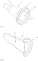
- Fig. 1a shows an inner shell 1 for a warhead according to a first embodiment of the invention, where the inner shell is formed as a spacer material, also known as a liner.
- the warhead is an arrangement adapted to assault a target and it may consist of a projectile, such as a grenade, or it may be a component in a projectile such as a grenade.
- the inner shell 1 is hollow, to enable the arrangement of an explosive therein.
- the inner shell 1 is also configured to receive a nose portion and an aft portion in its front 2 and rear 3 end, respectively.
- the nose portion and the aft portion may have a number of different configurations, depending on the desired properties of the warhead, but since they are not part of the present invention they are not shown in the drawings.
- the inner shell 1 is preferably made of a material which the person skilled in the art will consider to be appropriate to its purpose, usually a metal material, but it may also be a plastic or a composite, and many examples of the material are already known in the art.
- a tool 10 is arranged inside the inner shell 1, the tool being made preferably of homogeneous steel and being configured to handle high pressure and/or high temperature. In the case when the inner shell 1 is a spacer material, the spacer material thus acts like a driving mirror for projectiles.
- the bottom plate 33 of the HIP-container is also shown in the figure.
- Fig. 1b shows an alternative embodiment, where the inner shell 1 is configured as a grenade body, preferably made of machined metal, such as by conventional lathe work, or by additive manufacturing methods. Indications of where the projectiles will be arranged are made in the inner shell 1.
- the bottom plate 33 of the HIP-container is also shown in the figure.
- FIG. 2a shows one step in the manufacturing of a warhead 4 according to the invention.
- a network 5, comprising preshaped projectiles 20, is arranged around the inner shell 1, preferably so as to enclose the inner shell 1 in the circumferential direction.
- the network 5 stretches along a portion of the inner shell 1 in the axial direction, but in the preferred embodiment the front end 2 and the rear end 3 are left free for connection to the respective nose and aft portions.
- the network 5 in the embodiment shown has meshes 7 adapted to receive the shape of the preshaped projectiles 20.
- the size and shape of the meshes 7 vary somewhat in the axial direction of the warhead 4, in order to connect to the shape of the inner shell 1 with a radius varying somewhat in the axial direction.
- the shape of the meshes 7 may vary within certain limits, as can their size, and they are adapted to the size and shape of the preshaped projectiles 20.
- the preshaped projectiles 20 may also be called fragments and/or splinters.
- the preshaped projectiles are ball-shaped or spherical.
- the network 5 is designed to produce the intended retention of the projectiles, where the shape and size of the meshes 7 prevent the projectiles from passing through them.
- the meshes 7 may be configured, for example, in complete or partial circular shape, to ensure a secure retention of the preshaped projectiles 20 when the preshaped projectiles 20 are arranged against the inner shell 1 and enclosed by the network 5, which is shown in the embodiment of Fig. 2a .
- the material used to produce the network 5 is preferably a metal material, but it may also be a plastic or ceramic which is chosen to have properties, such as thermal properties or melting point, a brittleness after heat treatment, and an ability to form alloys with other material.
- the network can be made from a plate which is punched or otherwise machined to give it a suitable configuration.
- the network can be rolled or pressed into a shape suitable for an arrangement enclosing the inner shell 1 and the preshaped projectiles 20.
- One conceivable manufacturing method for the network 5 is to create a hole with the desired size in a plate, such as by punching, etching, laser cutting or some other production method which the skilled person considers to be suitable.
- the network shown is especially suitable for retention of preshaped projectiles having a cross section which is somewhat larger than the size of the meshes 7.
- the arranging of a number of preshaped projectiles 20 in the warhead is thus accomplished with the help of a network 5, which is either a standard product or which can be manufactured in a relatively easy and cost-effective manufacturing method.
- the network 5 does not need to be removed, but instead remains an integrated part of the warhead 4, which significantly simplifies the manufacturing process.
- the network 5 may also contribute to a controlled fragmentation of the warhead 4 in a way that enables a cost-effective production of the warhead 4.
- the bottom plate 33 of the HIP-container is also shown in the figure.
- Fig. 2b shows one step in the manufacturing of a warhead 4 according to a second, alternative embodiment of the invention, where the inner shell 1 is configured as a grenade body.
- a network 5, comprising preshaped projectiles 20, is arranged around the inner shell 1, preferably so as to enclose the inner shell 1 in the circumferential direction.
- the network 5 stretches along a portion of the inner shell 1 in the axial direction, but in the preferred embodiment the front end 2 and the rear end 3 are left free for connection to the respective nose and aft portions.
- the network 5 in the embodiment shown has meshes 7 adapted to receive the shape of the preshaped projectiles 20.
- the size and shape of the meshes 7 vary somewhat in the axial direction of the warhead 4, in order to connect to the shape of the inner shell 1 with a radius varying somewhat in the axial direction.
- the shape of the meshes 7 may vary within certain limits, as can their size, and they are adapted to the size and shape of the preshaped projectiles 20.
- the preshaped projectiles 20 may also be called fragments and/or splinters. In the configuration shown in Fig. 2b , the preshaped projectiles are ball-shaped or spherical.
- the network 5 is designed to produce the intended retention of the projectiles, where the shape and size of the meshes 7 prevent the projectiles from passing through them.
- the meshes 7 may be configured, for example, in complete or partial circular shape, to ensure a secure retention of the preshaped projectiles 20 when the preshaped projectiles 20 are arranged against the inner shell 1 and enclosed by the network 5, which is shown in the embodiment of Fig. 2b .
- the material used to produce the network 5 is preferably a metal material, but it may also be a plastic or ceramic which is chosen to have properties, such as thermal properties or melting point, a brittleness after heat treatment, and an ability to form alloys with other material.
- the network can be made from a plate which is punched or otherwise machined to give it a suitable configuration.
- the network can be rolled or pressed into a shape suitable for an arrangement enclosing the inner shell 1 and the preshaped projectiles 20.
- the bottom plate 33 of the HIP-container is also shown in the figure.
- Fig 3a shows the warhead 4 in a manufacturing step according to a first embodiment of the invention.
- An applied material 8 has been placed on top of the network 5 arranged on the inner shell 1 as shown in Fig 2a and the preshaped projectiles 20.
- Fig. 2a shows an inner shell 1 in the form of a spacer material.
- the application method is preferably some type of additive manufacturing method, where the material can be applied in powder form inside a HIP-container 30, which is a surrounding component arranged to retain the inner shell 1, arranged on the tool 10, where preshaped projectiles 20 enclosed by a network 5 are arranged on the inner shell and where powder in the form of applied material 8 is freely arranged in the HIP-container 30 enclosing the inner shell 1, the tool 10, the preshaped projectiles 20 and the network 5.
- HIP-container 30 is a surrounding component arranged to retain the inner shell 1, arranged on the tool 10, where preshaped projectiles 20 enclosed by a network 5 are arranged on the inner shell and where powder in the form of applied material 8 is freely arranged in the HIP-container 30 enclosing the inner shell 1, the tool 10, the preshaped projectiles 20 and the network 5.
- the temperatures applicable in accordance with HIP for the applied material 8 also mean that the material in the underlying network 5 is affected. With a suitable material choice for both the material in the network 5 and that in the applied material 8, the material in the network 5 remains brittle due to diffusion and/or partial melting, or it forms an alloy with the applied material 8.
- the HIP-container 30 is arranged with a connection device 31, 32 for evacuation of air and vacuum pumping before and/or during the course of the manufacturing method, and a bottom plate 33.
- the material in the network 5 and the applied material, or the powder 8 are chosen such that the applied material 8 and the network 5 together form a homogeneous whole with non-existent, controlled, or limited material variation in the portion of the resulting warhead 4 constituted by the applied material 8 and the network 5.
- the network 5 and the applied material 8 do not affect each other's physical properties more than that the layer of the applied material 8 becomes thinner on top of the material making up the network 5.
- the constituent materials and the temperatures during the material application are chosen such that the result is that the applied material 8 and the network 5 together form a whole which, depending on the choice of material, contains weakened areas where the network 5 was originally placed.
- the weakened areas in the whole formed by the applied material 8 and the network 5 will act as a controlled fragmentation upon bursting of the warhead 4.
- the portion of the applied material 8 which is arranged in the meshes 7 of the network 5 will form projectiles.
- This aspect will also be considered in the preferred embodiment when selecting the applied material 8, so that the projectiles formed in this way have a suitable mass, and when selecting the size and shape of the meshes, so that the projectiles formed in this way have a suitable size and shape and can interact with the preshaped projectiles 20 to achieve the maximum effect.
- the application method is preferably some type of additive manufacturing method, where the material can be applied in powder form inside a HIP-container 30, which is a surrounding component arranged to retain the inner shell 1, arranged on the tool 10, where preshaped projectiles 20 enclosed by a network 5 are arranged on the inner shell and where powder in the form of applied material 8 is freely arranged in the HIP-container 30 enclosing the inner shell 1, the tool 10, the preshaped projectiles 20 and the network 5.
- HIP-container 30 is a surrounding component arranged to retain the inner shell 1, arranged on the tool 10, where preshaped projectiles 20 enclosed by a network 5 are arranged on the inner shell and where powder in the form of applied material 8 is freely arranged in the HIP-container 30 enclosing the inner shell 1, the tool 10, the preshaped projectiles 20 and the network 5.
- the temperatures applicable in accordance with HIP for the applied material 8 also mean that the material in the underlying network 5 is affected. With a suitable material choice for both the material in the network 5 and that in the applied material 8, the material in the network 5 remains brittle due to diffusion and/or partial melting, or it forms an alloy with the applied material 8.
- the HIP-container 30 is arranged with a connection device 31, 32 for evacuation of air and vacuum pumping before and/or during the course of the manufacturing method, and a bottom plate 33.
- the material in the network 5 and the applied material, or the powder 8 are chosen such that the applied material 8 and the network 5 together form a whole with controlled material variation in the portion of the resulting warhead 4 constituted by the applied material 8 and the network 5.
- the network 5 and the applied material 8 do not affect each other's physical properties more than that the layer of the applied material 8 becomes thinner on top of the material making up the network 5.
- the constituent materials and the temperatures during the material application are chosen such that the result is that the applied material 8 and the network 5 together form a whole which, depending on the choice of material, contains weakened areas where the network 5 was originally placed.
- the weakened areas in the whole formed by the applied material 8 and the network 5 will act as a controlled fragmentation upon bursting of the warhead 4.
- the portion of the applied material 8 which is arranged in the meshes 7 of the network 5 will form projectiles.
- This aspect will also be considered in the preferred embodiment when selecting the applied material 8, so that the projectiles formed in this way have a suitable mass, and when selecting the pattern, size and shape of the meshes, so that the projectiles formed in this way have a suitable size, shape, and dispersal and can interact with the preshaped projectiles 20 to achieve the maximum effect.
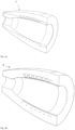
- Fig. 4a shows a casing for a warhead 4 manufactured according to the first embodiment after a production step of Hot Isostatic Pressing has been performed, the tool 10 has been removed from the inner shell 1, and the HIP-container has been machined away, for example, with a cutting type machining.
- the warhead 4 can now be called a HIPPED body and it can be finished to form a complete warhead 4, which can then be used as a component for manufacturing of projectiles, such as grenades.
- Fig. 4b shows a casing for a warhead 4 manufactured according to the second embodiment after a production step of Hot Isostatic Pressing has been performed, the tool 10 has been removed from the inner shell 1, and the HIP-container has been machined away, for example, with a cutting type machining.
- the warhead 4 can now be called a HIPPED body and it can be finished to form a complete warhead 4, which can then be used as a component for manufacturing of projectiles, such as grenades.
- Fig. 5 shows a manufacturing method for a warhead 100.
- the casing for the warhead 4 the warhead also being known as the active part or grenade body, is produced by Establishing of the casing 101, for example by a cutting type machining such as lathe work, alternatively by additive manufacturing, but it can also be produced by pressing or drawing, for example.
- the casing can also be called the inner shell 1 and it may also be constituted by a spacer material.
- the step of Arrangement of the tool 102 occurs, which means that a tool 10 is arranged so that the casing encloses the tool.
- the geometry of the tool corresponds to the internal geometry of the inner shell/casing and thus to the internal geometry of the warhead.
- the geometry is preferably configured such that the tool can be removed after the manufacturing method 100 has been performed.
- the preshaped projectiles 20 are arranged about the casing in the step Arrangement of preshaped projectiles 103.
- the preshaped projectiles 20 are retained by a network 5 in the step Arrangement of network 104.
- the preshaped projectiles 20 and the network 5 are arranged at the same time around the inner shell/casing.
- the preshaped projectiles 20 are held in place by a network-like structure which is integrated with the warhead 4 during the performance of the manufacturing method 100.
- the inner shell 1 together with the preshaped projectiles 20 and the network 5 are arranged together in a HIP-container 30 in the step Arrangement in the HIP-container 105.
- a HIP-container 30 is an arrangement where powder is placed so that the powder is altered under high temperature and high pressure to form a HIPPED body. After the casing together with the preshaped projectiles and the network have been arranged together in a HIP-container 30, powder is arranged in the HIP-container 30 in the step Powder is arranged in the HIP-container 106. After the powder material is arranged in the HIP-container 30, the HIP-container 30 is evacuated, vibrated, and closed so as to evenly divide the powder in the HIP-container 30 in the step Evacuation, vibration treatment and closure of the HIP-container 107.
- the HIP 108 is performed, that is, a gas is used to create an isostatic pressure in the HIP-container 30 by placing the gas in a connection device 31, 32 arranged on the HIP-container 30.
- the HIP-container Before the gas is placed in the HIP-container, the HIP-container can be vacuum pumped or otherwise evacuated of air or the filling gas/fluid arranged in the HIP-container 30 prior to the evacuation. At the same time, the entire HIP-container 30 is heated. The HIP-container and any surplus material is machined away in the step Machining of the HIP-container 109.
- the tool can be removed from the casing in the step Removal of tool 110.
- the body can undergo heat treatment 111, which means that the now assembled body is heated.
- the material is suitable for machining, such as a cutting type machining.
- a hardening of the HIPPED body can occur in the step Hardening 112.
- the number of preshaped projectiles, the material choice, the choice of geometrical shapes, the elements and parts making up the warhead will be adapted according to the weapon system(s), platform, and other design attributes in the particular instance.
- warheads all forms are covered, such as grenades containing projectiles, fragmentation grenades, guided missiles, missiles and rockets. Also other forms of warheads such as hand grenades and different types of mines.
Landscapes
- Engineering & Computer Science (AREA)
- General Engineering & Computer Science (AREA)
- Manufacturing & Machinery (AREA)
- Chemical & Material Sciences (AREA)
- Combustion & Propulsion (AREA)
- Powder Metallurgy (AREA)
- Aiming, Guidance, Guns With A Light Source, Armor, Camouflage, And Targets (AREA)
- Press Drives And Press Lines (AREA)
- Press-Shaping Or Shaping Using Conveyers (AREA)
Claims (8)
- Verfahren zur Herstellung einer Komponente für einen Gefechtskopf (4), wobei das Verfahren die Schritte umfasst:i.) eine Innenschale (1) auf einem Werkzeug (10) angeordnet ist,ii.) Vorgeformte Geschosse (20) sind auf der Innenschale in einem umschließenden Netz (5) angeordnet,iii.) Das Pulver (8) ist so angeordnet, dass es die vorgeformten Geschosse umschließt,iv.) das Pulver so gepresst wird, dass das Pulver, die vorgeformten Geschosse, die und die innere Schale sind miteinander verbunden,v.) das Werkzeug wird aus dem aus dem Pulver, den vorgeformten Geschossen, dem umschließenden Netz und der inneren Schale gebildeten Bauteil entfernt.
- Verfahren nach Anspruch 1, dadurch gekennzeichnet, dass das Pulver gepresst wird durch durch hohen Druck und Hitze, auch bekannt als Heiß-Isostatisches Pressen (HIP).
- Verfahren nach einem der Ansprüche 1 und 2, dadurch gekennzeichnet, dass das Pulver, die vorgeformten Geschosse und die Innenhülle zusammen in einem geeignet angepassten HIP-Behälter (30) angeordnet sind.
- Verfahren nach einem der Ansprüche 1 bis 3, dadurch gekennzeichnet, dass die Innenhülle eine Hülle für einen Granatenkörper ist.
- Verfahren nach einem der Ansprüche 1 bis 3, dadurch gekennzeichnet, dass die Innenschale ist ein Abstandshaltermaterial.
- Verfahren nach einem der Ansprüche 1 bis 6, dadurch gekennzeichnet, dass das Netz mit Maschen (7) gebildet wird, um die vorgeformten Geschosse zurückzuhalten, wenn das Netz um die auf der Innenschale angeordneten vorgeformten Geschosse herum angeordnet wird.
- Gefechtskopf, hergestellt durch ein Verfahren nach einem Ansprüche 1 bis 6.
- Gefechtskopf nach Anspruch 7, bestehend aus einem Projektil.
Applications Claiming Priority (2)
| Application Number | Priority Date | Filing Date | Title |
|---|---|---|---|
| SE2000045A SE544578C2 (sv) | 2020-02-28 | 2020-02-28 | Metod för framställning av en komponent för en stridsdel |
| PCT/SE2021/050072 WO2021173053A1 (en) | 2020-02-28 | 2021-02-01 | Warhead |
Publications (4)
| Publication Number | Publication Date |
|---|---|
| EP4111128A1 EP4111128A1 (de) | 2023-01-04 |
| EP4111128A4 EP4111128A4 (de) | 2024-03-06 |
| EP4111128B1 true EP4111128B1 (de) | 2025-06-11 |
| EP4111128C0 EP4111128C0 (de) | 2025-06-11 |
Family
ID=77491804
Family Applications (1)
| Application Number | Title | Priority Date | Filing Date |
|---|---|---|---|
| EP21761359.5A Active EP4111128B1 (de) | 2020-02-28 | 2021-02-01 | Gefechtskopf |
Country Status (6)
| Country | Link |
|---|---|
| US (1) | US12135196B2 (de) |
| EP (1) | EP4111128B1 (de) |
| JP (1) | JP7607047B2 (de) |
| CA (1) | CA3172881A1 (de) |
| SE (1) | SE544578C2 (de) |
| WO (1) | WO2021173053A1 (de) |
Families Citing this family (3)
| Publication number | Priority date | Publication date | Assignee | Title |
|---|---|---|---|---|
| US12072171B1 (en) * | 2016-03-22 | 2024-08-27 | Northrop Grumman Systems Corporation | Prefragmented warheads with enhanced performance |
| SE545386C2 (sv) * | 2021-05-19 | 2023-07-25 | Bae Systems Bofors Ab | Metod för framställning av en komponent för en stridsdel |
| US12298115B2 (en) * | 2023-09-21 | 2025-05-13 | Raytheon Company | Vacuum insulated warhead |
Family Cites Families (20)
| Publication number | Priority date | Publication date | Assignee | Title |
|---|---|---|---|---|
| DE2129196C3 (de) | 1971-06-12 | 1975-11-13 | Fa. Diehl, 8500 Nuernberg | Splitterkörper für Splittergeschosse und -gefechtskopfe |
| DE2460013C3 (de) * | 1974-12-19 | 1978-08-24 | Sintermetallwerk Krebsoege Gmbh, 5608 Radevormwald | Verfahren zum Herstellen metallischer Formkörper |
| DE2539684C1 (de) * | 1975-09-06 | 1985-10-10 | Diehl GmbH & Co, 8500 Nürnberg | Splitterhuelle fuer Geschosse,Gefechtskoepfe,Wurfmunition u.dgl. |
| SE416678B (sv) * | 1976-08-31 | 1981-01-26 | Diehl Fa | Forfarande for framstellning av splitterholje for projektiler, stridsspetsar, kastammunition och dylikt |
| DE2852658A1 (de) * | 1978-12-06 | 1980-06-12 | Diehl Gmbh & Co | Verfahren zur herstellung metallischer formkoerper |
| DE2852657C2 (de) * | 1978-12-06 | 1984-10-04 | Diehl GmbH & Co, 8500 Nürnberg | Splitterkörper für Splittergeschosse |
| DE2852659A1 (de) * | 1978-12-06 | 1980-06-19 | Diehl Gmbh & Co | Verfahren zur herstellung metallischer formkoerper |
| SE450294B (sv) * | 1984-04-02 | 1987-06-15 | Bofors Ab | Granatholje innefattande forformade splitter samt sett for dess tillverkning |
| US7614348B2 (en) * | 2006-08-29 | 2009-11-10 | Alliant Techsystems Inc. | Weapons and weapon components incorporating reactive materials |
| SE536515C2 (sv) * | 2002-01-22 | 2014-01-21 | Bofors Defence Ab | Sätt att framställa explosivämnesladdade stridsdelar |
| US8689669B2 (en) * | 2003-04-30 | 2014-04-08 | Bofors Defence Ab | Method of producing warheads containing explosives |
| JP5310454B2 (ja) * | 2009-10-01 | 2013-10-09 | ダイキン工業株式会社 | 弾頭部 |
| CN103575169B (zh) * | 2013-11-13 | 2015-04-08 | 北京科技大学 | 一种高比重高硬度霰弹枪圆柱形弹丸的制造方法 |
| GB2526262B (en) * | 2014-05-02 | 2021-04-28 | Mbda Uk Ltd | Composite reactive material for use in a munition |
| US9759533B2 (en) * | 2015-03-02 | 2017-09-12 | Nostromo Holdings, Llc | Low collateral damage bi-modal warhead assembly |
| SG11201805036WA (en) * | 2016-01-15 | 2018-07-30 | Saab Bofors Dynamics Switzerland Ltd | Warhead |
| US11041704B1 (en) * | 2017-07-25 | 2021-06-22 | The United States Of America As Represented By The Secretary Of The Army | Method of manufacturing composite projectile body embedded with preformed fragments |
| SE543620C2 (sv) * | 2017-12-05 | 2021-04-20 | Bae Systems Bofors Ab | Verkansdel med förformade element |
| SE544060C2 (sv) * | 2019-03-19 | 2021-11-30 | Bae Systems Bofors Ab | En stridsdel och ett förfarande för framställning av en stridsdel |
| US10712137B1 (en) * | 2019-04-26 | 2020-07-14 | The United States Of America As Represented By The Secretary Of The Army | Method for making a composite fragmentation cap that is integrally formed onto a projectile body |
-
2020
- 2020-02-28 SE SE2000045A patent/SE544578C2/sv unknown
-
2021
- 2021-02-01 CA CA3172881A patent/CA3172881A1/en active Pending
- 2021-02-01 US US17/802,185 patent/US12135196B2/en active Active
- 2021-02-01 WO PCT/SE2021/050072 patent/WO2021173053A1/en not_active Ceased
- 2021-02-01 JP JP2022551740A patent/JP7607047B2/ja active Active
- 2021-02-01 EP EP21761359.5A patent/EP4111128B1/de active Active
Also Published As
| Publication number | Publication date |
|---|---|
| WO2021173053A1 (en) | 2021-09-02 |
| US20230358519A1 (en) | 2023-11-09 |
| SE2000045A1 (sv) | 2021-08-29 |
| EP4111128A1 (de) | 2023-01-04 |
| US12135196B2 (en) | 2024-11-05 |
| CA3172881A1 (en) | 2021-09-02 |
| EP4111128C0 (de) | 2025-06-11 |
| EP4111128A4 (de) | 2024-03-06 |
| SE544578C2 (sv) | 2022-07-26 |
| JP2023516003A (ja) | 2023-04-17 |
| JP7607047B2 (ja) | 2024-12-26 |
Similar Documents
| Publication | Publication Date | Title |
|---|---|---|
| EP4111128B1 (de) | Gefechtskopf | |
| US4644867A (en) | Shell case with non-compressible fragments metallurgically bonded to the casing | |
| US11940254B2 (en) | Low drag, high density core projectile | |
| EP1290398B1 (de) | Beschichtete metallische partikel zur verbesserung der leistung von ölfelderhohlladungen | |
| JP7439120B2 (ja) | 弾頭 | |
| US6694888B2 (en) | Frangible bullet | |
| US6591730B2 (en) | Cap for a multi-component ammunition projectile and method | |
| US20030213396A1 (en) | Bullet | |
| WO2008085189A9 (en) | Co-sintered multi-system tungsten alloy composite | |
| US11041704B1 (en) | Method of manufacturing composite projectile body embedded with preformed fragments | |
| US4296180A (en) | Process for the production of metallic formed members | |
| KR102203134B1 (ko) | 연성 외장에 의해 둘러싸인 코어를 포함하는 관통자 및 그 관통자의 제조방법 | |
| US4292829A (en) | Process for the production of metallic formed members | |
| US20110176951A1 (en) | Method and device for producing a tubular solid body from a refractory tungsten heavy metal alloy, particularly as a semi-finished product for the production of a penetrator for a kinetic energy projectile with fragmentation effect | |
| DE102016007976B4 (de) | Vorfragmentierung eines Sprengkopfes | |
| EP4341637B1 (de) | Verfahren zur herstellung einer gefechtskopfkomponente | |
| US20250276365A1 (en) | Muzzle brake and method for manufacturing muzzle brake | |
| JP3853598B2 (ja) | 発射体とその製造方法 | |
| WO2025250064A1 (en) | Barrels, methods of manufacturing barrels and barrel segments and launching device comprising barrels | |
| RU2313060C1 (ru) | Способ изготовления корпуса осколочной боевой части /варианты/ | |
| EP3187284B1 (de) | Dynamische verbindung von pulvermetallurgiematerialien |
Legal Events
| Date | Code | Title | Description |
|---|---|---|---|
| STAA | Information on the status of an ep patent application or granted ep patent |
Free format text: STATUS: THE INTERNATIONAL PUBLICATION HAS BEEN MADE |
|
| PUAI | Public reference made under article 153(3) epc to a published international application that has entered the european phase |
Free format text: ORIGINAL CODE: 0009012 |
|
| STAA | Information on the status of an ep patent application or granted ep patent |
Free format text: STATUS: REQUEST FOR EXAMINATION WAS MADE |
|
| 17P | Request for examination filed |
Effective date: 20220905 |
|
| AK | Designated contracting states |
Kind code of ref document: A1 Designated state(s): AL AT BE BG CH CY CZ DE DK EE ES FI FR GB GR HR HU IE IS IT LI LT LU LV MC MK MT NL NO PL PT RO RS SE SI SK SM TR |
|
| DAV | Request for validation of the european patent (deleted) | ||
| DAX | Request for extension of the european patent (deleted) | ||
| A4 | Supplementary search report drawn up and despatched |
Effective date: 20240201 |
|
| RIC1 | Information provided on ipc code assigned before grant |
Ipc: F42B 33/00 20060101ALI20240126BHEP Ipc: F42B 12/32 20060101AFI20240126BHEP |
|
| GRAP | Despatch of communication of intention to grant a patent |
Free format text: ORIGINAL CODE: EPIDOSNIGR1 |
|
| STAA | Information on the status of an ep patent application or granted ep patent |
Free format text: STATUS: GRANT OF PATENT IS INTENDED |
|
| INTG | Intention to grant announced |
Effective date: 20250328 |
|
| GRAS | Grant fee paid |
Free format text: ORIGINAL CODE: EPIDOSNIGR3 |
|
| GRAA | (expected) grant |
Free format text: ORIGINAL CODE: 0009210 |
|
| STAA | Information on the status of an ep patent application or granted ep patent |
Free format text: STATUS: THE PATENT HAS BEEN GRANTED |
|
| AK | Designated contracting states |
Kind code of ref document: B1 Designated state(s): AL AT BE BG CH CY CZ DE DK EE ES FI FR GB GR HR HU IE IS IT LI LT LU LV MC MK MT NL NO PL PT RO RS SE SI SK SM TR |
|
| REG | Reference to a national code |
Ref country code: GB Ref legal event code: FG4D |
|
| REG | Reference to a national code |
Ref country code: CH Ref legal event code: EP |
|
| REG | Reference to a national code |
Ref country code: DE Ref legal event code: R096 Ref document number: 602021032165 Country of ref document: DE |
|
| REG | Reference to a national code |
Ref country code: IE Ref legal event code: FG4D |
|
| U01 | Request for unitary effect filed |
Effective date: 20250611 |
|
| U07 | Unitary effect registered |
Designated state(s): AT BE BG DE DK EE FI FR IT LT LU LV MT NL PT RO SE SI Effective date: 20250708 |
|
| PG25 | Lapsed in a contracting state [announced via postgrant information from national office to epo] |
Ref country code: ES Free format text: LAPSE BECAUSE OF FAILURE TO SUBMIT A TRANSLATION OF THE DESCRIPTION OR TO PAY THE FEE WITHIN THE PRESCRIBED TIME-LIMIT Effective date: 20250611 |
|
| PG25 | Lapsed in a contracting state [announced via postgrant information from national office to epo] |
Ref country code: GR Free format text: LAPSE BECAUSE OF FAILURE TO SUBMIT A TRANSLATION OF THE DESCRIPTION OR TO PAY THE FEE WITHIN THE PRESCRIBED TIME-LIMIT Effective date: 20250912 Ref country code: NO Free format text: LAPSE BECAUSE OF FAILURE TO SUBMIT A TRANSLATION OF THE DESCRIPTION OR TO PAY THE FEE WITHIN THE PRESCRIBED TIME-LIMIT Effective date: 20250911 |
|
| PG25 | Lapsed in a contracting state [announced via postgrant information from national office to epo] |
Ref country code: HR Free format text: LAPSE BECAUSE OF FAILURE TO SUBMIT A TRANSLATION OF THE DESCRIPTION OR TO PAY THE FEE WITHIN THE PRESCRIBED TIME-LIMIT Effective date: 20250611 |
|
| PG25 | Lapsed in a contracting state [announced via postgrant information from national office to epo] |
Ref country code: RS Free format text: LAPSE BECAUSE OF FAILURE TO SUBMIT A TRANSLATION OF THE DESCRIPTION OR TO PAY THE FEE WITHIN THE PRESCRIBED TIME-LIMIT Effective date: 20250911 |
|
| PG25 | Lapsed in a contracting state [announced via postgrant information from national office to epo] |
Ref country code: IS Free format text: LAPSE BECAUSE OF FAILURE TO SUBMIT A TRANSLATION OF THE DESCRIPTION OR TO PAY THE FEE WITHIN THE PRESCRIBED TIME-LIMIT Effective date: 20251011 |
|
| PG25 | Lapsed in a contracting state [announced via postgrant information from national office to epo] |
Ref country code: SM Free format text: LAPSE BECAUSE OF FAILURE TO SUBMIT A TRANSLATION OF THE DESCRIPTION OR TO PAY THE FEE WITHIN THE PRESCRIBED TIME-LIMIT Effective date: 20250611 |
|
| PG25 | Lapsed in a contracting state [announced via postgrant information from national office to epo] |
Ref country code: CZ Free format text: LAPSE BECAUSE OF FAILURE TO SUBMIT A TRANSLATION OF THE DESCRIPTION OR TO PAY THE FEE WITHIN THE PRESCRIBED TIME-LIMIT Effective date: 20250611 |
|
| PG25 | Lapsed in a contracting state [announced via postgrant information from national office to epo] |
Ref country code: PL Free format text: LAPSE BECAUSE OF FAILURE TO SUBMIT A TRANSLATION OF THE DESCRIPTION OR TO PAY THE FEE WITHIN THE PRESCRIBED TIME-LIMIT Effective date: 20250611 |
|
| PG25 | Lapsed in a contracting state [announced via postgrant information from national office to epo] |
Ref country code: SK Free format text: LAPSE BECAUSE OF FAILURE TO SUBMIT A TRANSLATION OF THE DESCRIPTION OR TO PAY THE FEE WITHIN THE PRESCRIBED TIME-LIMIT Effective date: 20250611 |
|
| U20 | Renewal fee for the european patent with unitary effect paid |
Year of fee payment: 6 Effective date: 20260227 |
|
| PLBE | No opposition filed within time limit |
Free format text: ORIGINAL CODE: 0009261 |
|
| STAA | Information on the status of an ep patent application or granted ep patent |
Free format text: STATUS: NO OPPOSITION FILED WITHIN TIME LIMIT |
|
| REG | Reference to a national code |
Ref country code: CH Ref legal event code: L10 Free format text: ST27 STATUS EVENT CODE: U-0-0-L10-L00 (AS PROVIDED BY THE NATIONAL OFFICE) Effective date: 20260423 |