EP4111146B1 - Sélection de critères de détection sonore passive dans un réseau iot d'éclairage - Google Patents
Sélection de critères de détection sonore passive dans un réseau iot d'éclairage Download PDFInfo
- Publication number
- EP4111146B1 EP4111146B1 EP21704821.4A EP21704821A EP4111146B1 EP 4111146 B1 EP4111146 B1 EP 4111146B1 EP 21704821 A EP21704821 A EP 21704821A EP 4111146 B1 EP4111146 B1 EP 4111146B1
- Authority
- EP
- European Patent Office
- Prior art keywords
- speakers
- baseline
- microphones
- audio
- building space
- Prior art date
- Legal status (The legal status is an assumption and is not a legal conclusion. Google has not performed a legal analysis and makes no representation as to the accuracy of the status listed.)
- Active
Links
Images


Classifications
-
- G—PHYSICS
- G01—MEASURING; TESTING
- G01V—GEOPHYSICS; GRAVITATIONAL MEASUREMENTS; DETECTING MASSES OR OBJECTS; TAGS
- G01V1/00—Seismology; Seismic or acoustic prospecting or detecting
- G01V1/001—Acoustic presence detection
-
- G—PHYSICS
- G08—SIGNALLING
- G08C—TRANSMISSION SYSTEMS FOR MEASURED VALUES, CONTROL OR SIMILAR SIGNALS
- G08C23/00—Non-electrical signal transmission systems, e.g. optical systems
- G08C23/02—Non-electrical signal transmission systems, e.g. optical systems using infrasonic, sonic or ultrasonic waves
-
- G—PHYSICS
- G01—MEASURING; TESTING
- G01H—MEASUREMENT OF MECHANICAL VIBRATIONS OR ULTRASONIC, SONIC OR INFRASONIC WAVES
- G01H3/00—Measuring characteristics of vibrations by using a detector in a fluid
- G01H3/10—Amplitude; Power
- G01H3/12—Amplitude; Power by electric means
- G01H3/125—Amplitude; Power by electric means for representing acoustic field distribution
-
- G—PHYSICS
- G06—COMPUTING OR CALCULATING; COUNTING
- G06F—ELECTRIC DIGITAL DATA PROCESSING
- G06F3/00—Input arrangements for transferring data to be processed into a form capable of being handled by the computer; Output arrangements for transferring data from processing unit to output unit, e.g. interface arrangements
- G06F3/01—Input arrangements or combined input and output arrangements for interaction between user and computer
- G06F3/048—Interaction techniques based on graphical user interfaces [GUI]
- G06F3/0481—Interaction techniques based on graphical user interfaces [GUI] based on specific properties of the displayed interaction object or a metaphor-based environment, e.g. interaction with desktop elements like windows or icons, or assisted by a cursor's changing behaviour or appearance
-
- H—ELECTRICITY
- H04—ELECTRIC COMMUNICATION TECHNIQUE
- H04R—LOUDSPEAKERS, MICROPHONES, GRAMOPHONE PICK-UPS OR LIKE ACOUSTIC ELECTROMECHANICAL TRANSDUCERS; ELECTRIC HEARING AIDS; PUBLIC ADDRESS SYSTEMS
- H04R1/00—Details of transducers, loudspeakers or microphones
- H04R1/20—Arrangements for obtaining desired frequency or directional characteristics
- H04R1/32—Arrangements for obtaining desired frequency or directional characteristics for obtaining desired directional characteristic only
- H04R1/40—Arrangements for obtaining desired frequency or directional characteristics for obtaining desired directional characteristic only by combining a number of identical transducers
- H04R1/403—Arrangements for obtaining desired frequency or directional characteristics for obtaining desired directional characteristic only by combining a number of identical transducers loud-speakers
-
- H—ELECTRICITY
- H04—ELECTRIC COMMUNICATION TECHNIQUE
- H04R—LOUDSPEAKERS, MICROPHONES, GRAMOPHONE PICK-UPS OR LIKE ACOUSTIC ELECTROMECHANICAL TRANSDUCERS; ELECTRIC HEARING AIDS; PUBLIC ADDRESS SYSTEMS
- H04R1/00—Details of transducers, loudspeakers or microphones
- H04R1/20—Arrangements for obtaining desired frequency or directional characteristics
- H04R1/32—Arrangements for obtaining desired frequency or directional characteristics for obtaining desired directional characteristic only
- H04R1/40—Arrangements for obtaining desired frequency or directional characteristics for obtaining desired directional characteristic only by combining a number of identical transducers
- H04R1/406—Arrangements for obtaining desired frequency or directional characteristics for obtaining desired directional characteristic only by combining a number of identical transducers microphones
-
- H—ELECTRICITY
- H04—ELECTRIC COMMUNICATION TECHNIQUE
- H04R—LOUDSPEAKERS, MICROPHONES, GRAMOPHONE PICK-UPS OR LIKE ACOUSTIC ELECTROMECHANICAL TRANSDUCERS; ELECTRIC HEARING AIDS; PUBLIC ADDRESS SYSTEMS
- H04R3/00—Circuits for transducers
- H04R3/005—Circuits for transducers for combining the signals of two or more microphones
-
- H—ELECTRICITY
- H04—ELECTRIC COMMUNICATION TECHNIQUE
- H04R—LOUDSPEAKERS, MICROPHONES, GRAMOPHONE PICK-UPS OR LIKE ACOUSTIC ELECTROMECHANICAL TRANSDUCERS; ELECTRIC HEARING AIDS; PUBLIC ADDRESS SYSTEMS
- H04R3/00—Circuits for transducers
- H04R3/12—Circuits for transducers for distributing signals to two or more loudspeakers
-
- H—ELECTRICITY
- H05—ELECTRIC TECHNIQUES NOT OTHERWISE PROVIDED FOR
- H05B—ELECTRIC HEATING; ELECTRIC LIGHT SOURCES NOT OTHERWISE PROVIDED FOR; CIRCUIT ARRANGEMENTS FOR ELECTRIC LIGHT SOURCES, IN GENERAL
- H05B47/00—Circuit arrangements for operating light sources in general, i.e. where the type of light source is not relevant
- H05B47/10—Controlling the light source
- H05B47/105—Controlling the light source in response to determined parameters
- H05B47/115—Controlling the light source in response to determined parameters by determining the presence or movement of objects or living beings
- H05B47/12—Controlling the light source in response to determined parameters by determining the presence or movement of objects or living beings by detecting audible sound
-
- H—ELECTRICITY
- H04—ELECTRIC COMMUNICATION TECHNIQUE
- H04R—LOUDSPEAKERS, MICROPHONES, GRAMOPHONE PICK-UPS OR LIKE ACOUSTIC ELECTROMECHANICAL TRANSDUCERS; ELECTRIC HEARING AIDS; PUBLIC ADDRESS SYSTEMS
- H04R2201/00—Details of transducers, loudspeakers or microphones covered by H04R1/00 but not provided for in any of its subgroups
- H04R2201/40—Details of arrangements for obtaining desired directional characteristic by combining a number of identical transducers covered by H04R1/40 but not provided for in any of its subgroups
- H04R2201/401—2D or 3D arrays of transducers
-
- Y—GENERAL TAGGING OF NEW TECHNOLOGICAL DEVELOPMENTS; GENERAL TAGGING OF CROSS-SECTIONAL TECHNOLOGIES SPANNING OVER SEVERAL SECTIONS OF THE IPC; TECHNICAL SUBJECTS COVERED BY FORMER USPC CROSS-REFERENCE ART COLLECTIONS [XRACs] AND DIGESTS
- Y02—TECHNOLOGIES OR APPLICATIONS FOR MITIGATION OR ADAPTATION AGAINST CLIMATE CHANGE
- Y02B—CLIMATE CHANGE MITIGATION TECHNOLOGIES RELATED TO BUILDINGS, e.g. HOUSING, HOUSE APPLIANCES OR RELATED END-USER APPLICATIONS
- Y02B20/00—Energy efficient lighting technologies, e.g. halogen lamps or gas discharge lamps
- Y02B20/40—Control techniques providing energy savings, e.g. smart controller or presence detection
Definitions
- the present disclosure is directed generally to determining selection criteria for passive sound sensing in a lighting Internet of Things (IoT) system for evaluating characteristics of a building space, such as occupancy detection and/or people counting in a room.
- IoT lighting Internet of Things
- Connected lighting luminaires with sensor bundles have been developed and integrated into Internet of Things (IoT) systems. These sensor bundles may have embedded microphones, thermopile sensors, temperature sensors, relative humidity sensors, and additional sensors.
- the connected lighting luminaires may further include embedded speakers. These systems may use synchronized microphones and speakers of the same luminaire to transmit and receive an audio signal to determine building space occupancy. Modern commercial spaces often include connected speakers arranged independently from the luminaires. In fact, some office spaces may have dozens of connected lighting luminaires (each with an embedded microphone) and several connected speakers. Attempting to evaluate characteristics, such as occupancy or people count, for a portion of the building space utilizing every microphone and speaker would be highly inefficient, and could overwhelm the limited computational capacity of the connected lighting luminaires.
- US 2017/299425 A1 discloses a smart home system. The presence of a person in a room may be detected. Thereto, in the room there is a speaker generating sound which is received by a microphone.
- a channel can be considered to be present between speaker and microphone with multipath components.
- There is a training mode wherein the sound received by the microphone, being representative for an empty room, is stored.
- the detection mode sound is generated by the speaker and picked up by the microphone.
- the presence detection system compares received sound by microphone to empty room sound. If the difference is over a threshold, presence of a person is detected and for example the lighting may be adjusted.
- the present disclosure is directed generally to a connected lighting system configured to select independent microphones and speakers to efficiently evaluate one or more characteristics of a selected portion of a building space, such as a portion of a room. These characteristics may include occupancy status (occupied or unoccupied), people count, fall detection, breathing detection, and more.
- the system associates each microphone with one or more areas of the building space during the commissioning process.
- the system either determines or retrieves a baseline channel matrix representative of the strength of the audio multipath transmission channel between each pair of microphone and speaker when the building space is in baseline condition. Based on the selected portion of the building space, the baseline channel matrix, and the commissioning process, the system then selects the combinations of microphones and speakers to most efficiently evaluate the characteristics.
- the system then utilizes the selected speakers to transmit audio signals, and generates a characteristic channel response matrix based on the audio samples received by the selected microphones.
- the system then analyzes the characteristic channel response matrix in light of the baseline channel matrix to determine the characteristic of the selected portion of the building space.
- a system for evaluating a characteristic of a portion of a building space includes a plurality of speakers.
- each of the plurality of speakers may be directional.
- the system further includes a plurality of microphones.
- each of the plurality of microphones may be omnidirectional.
- the system further includes a plurality of pairs.
- Each pair includes at least one of the plurality of microphones and at least one of the plurality of speakers.
- Each pair forms one of a plurality of audio multipath transmission channels.
- At least one of the plurality of pairs is associated with at least one of the one or more detection areas within the portion of the building space.
- the system further includes a controller.
- the controller is communicatively coupled to each of the plurality of speakers.
- the controller is also communicatively coupled to each of the plurality of microphones.
- the controller is configured to select one or more of the one or more detection areas.
- the system may further include a user interface configured to receive one or more detection area selections from a user.
- the controller is further configured to activate one or more of the plurality of microphones to capture one or more audio samples.
- Each of the activated microphones corresponds to at least one of the pairs associated with one or more of the selected detection areas.
- the controller is further configured to select one or more of the plurality of speakers based on a baseline channel response matrix and the activated microphones.
- the controller is further configured to transmit a command signal to each of the selected speakers.
- the selected speakers are configured to generate a plurality of audio signals based on the command signal.
- the selected speakers may be configured to sequentially transmit one of the plurality of audio signals.
- the selected speakers may be configured to simultaneously transmit one of the plurality of audio signals.
- the audio signals transmitted simultaneously are orthogonal.
- each of the plurality of audio signals may have a frequency greater than or equal to 16 kHz.
- the controller is further configured to determine a characteristic channel response matrix based on the audio samples and the audio signals.
- the controller is further configured to evaluate the characteristic of the portion of the building space based on the characteristic channel response matrix and the baseline channel response matrix.
- the baseline channel response matrix represents an audio transmission channel between the one or more of the plurality of microphones and the one or more of the plurality of speakers of the portion of the building space.
- the system may further include a plurality of luminaires.
- Each luminaire may include one or more of the plurality of microphones.
- each of the plurality of speakers may be arranged in the building space apart from the plurality of luminaires.
- the controller may be further configured to determine the baseline channel response matrix by: (1) activating each of the plurality of microphones to capture one or more baseline audio samples; (2) transmitting a baseline command signals to each of the plurality of speakers while the building space is in baseline condition, wherein each of the speakers are configured to generate a plurality of baseline audio signals based on the baseline command signal; and (3) calculating the baseline channel response matrix based on the baseline audio signals and the baseline audio samples.
- the system may further include a commissioning subsystem.
- the commissioning subsystem may be configured to associate one or more of the plurality of pairs with one or more the one or more detection areas.
- a method for evaluating a characteristic of a portion of a building space includes selecting one or more of one or more detection areas. The one or more detection areas are within the portion of the building space.
- the method further includes activating one or more of a plurality of microphones to capture one or more audio samples.
- Each of the activated microphones corresponds to at least one of a plurality of pairs associated with one or more of the selected detection areas.
- Each pair includes at least one of the plurality of microphones and at least one of a plurality of speakers.
- Each pair forms one of a plurality of audio multipath transmission channels.
- the method further includes selecting one or more of the plurality of speakers based on a baseline channel response matrix and the activated microphones.
- the method further includes transmitting, via each of the selected speakers, one of a plurality of audio signals.
- the method further includes determining a characteristic channel response matrix based on the audio samples and the audio signals.
- the method further includes evaluating the characteristic of the portion of the building space based on the characteristic channel response matrix and the baseline channel response matrix.
- the method may further include activating each of the plurality of microphones to capture one or more baseline audio samples.
- the method may further include transmitting, via each of the plurality of speakers, one of a plurality of baseline audio signals while the building space is in baseline condition.
- the method may further include calculating the baseline channel response matrix based on the baseline audio signals and the baseline audio samples.
- the method may further include associating, via a commissioning subsystem, one or more of the plurality of pairs with one or more of the plurality of detection areas.
- a processor or controller may be associated with one or more storage media (generically referred to herein as "memory,” e.g., volatile and non-volatile computer memory such as RAM, PROM, EPROM, and EEPROM, floppy disks, compact disks, optical disks, magnetic tape, etc.).
- the storage media may be encoded with one or more programs that, when executed on one or more processors and/or controllers, perform at least some of the functions discussed herein.
- Various storage media may be fixed within a processor or controller or may be transportable, such that the one or more programs stored thereon can be loaded into a processor or controller so as to implement various aspects as discussed herein.
- program or “computer program” are used herein in a generic sense to refer to any type of computer code (e.g., software or microcode) that can be employed to program one or more processors or controllers.
- the present disclosure is directed generally to a connected lighting system configured to select independent microphones and speakers to efficiently evaluate one or more characteristics of a selected portion of a building space, such as a portion of a room. These characteristics may include occupancy, people count, fall detection, and more.
- the system associates each microphone with one or more areas of the building space during the commissioning process. In a preferred example, an area corresponds to a desk in an office space.
- the system either determines or retrieves a baseline channel matrix representative of the strength of the audio multipath transmission channel between each pair of microphone and speaker when the building space is in baseline condition. In baseline condition, the building space is typically unoccupied and either completely empty, or outfitted with only fixed-position furniture.
- the system Based on the selected portion of the building space, the baseline channel matrix, and the commissioning process, the system then selects the combinations of microphones and speakers to most efficiently evaluate the desired characteristics.
- the system then utilizes the selected speakers to transmit audio signals, and generates a characteristic channel response matrix based on the audio samples captured by the selected microphones.
- the speakers transmit a series of audio signals, and the system generates a series of characteristic channel response matrices, over a time interval.
- the speakers simultaneously transmit the audio signals of the series, and the signals are orthogonal to prevent signal interference.
- the system analyzes the one or more characteristic channel response matrices in light of the baseline channel matrix to determine the characteristic of the selected portion of the building space.
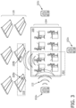
- a system 100 for evaluating a characteristic 136 of a portion 202 of a building space 200 may be provided.
- the characteristic 136 may be whether the portion 202 of the building space 200 is occupied or unoccupied.
- the characteristic 136 may be a count of the number of people within the portion 202 of the building space 200.
- the characteristic 136 may be whether or not a person has fallen in the portion 202 of the building space 200.
- the characteristic 136 may be a measure of vital signs of a person within the portion 202 of the building space 200, such as breathing detection.
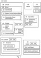
- the system 100 may include a plurality of speakers 102, a plurality of luminaires 120, each luminaire including a microphone 104, a controller 106, a user interface 126, and a commissioning subsystem 130. Each component of the system 100 may be configured to communicate via wired and/or wireless network 400.
- a typical system 100 may include three speakers 102 and six microphones 104.
- the system 100 includes a plurality of speakers 102.
- each of the plurality of speakers 102 may be directional.
- Each speaker 102 may include a transceiver 420 to communicate with the other components of the system 100.
- one of the speakers 102 may be a smart speaker, such as Amazon's Alexa.
- the speakers 102 are configured to utilize one or more electro-acoustic transducers to generate audio signals 132 based on one or a series of command signals 114 generated by the controller 106.
- the configuration (frequency, amplitude, modulation, etc.) of the audio signals 132 may be stored in a memory associated with the speakers 102.
- the speakers are triggered to transmit one or more audio signals 132 in the building space 200 upon receiving one or more command signals 114 from the controller 106 via the network 400.
- the plurality of speakers 102 may include smart speakers or any other speakers 102 with memory storage capabilities.
- the system 100 analyzes the impact of the aspects of the relevant portion 202 of the building space 200 (such as furniture and people) on the audio signals 132 to evaluate the desired characteristics 136.
- the system 100 further includes a plurality of microphones 104.
- each of the plurality of microphones 104 may be omnidirectional.
- the microphones When activated by the system 100, the microphones are configured to capture audio samples 108 corresponding to the audio signals 132 transmitted by the speakers 102.
- the microphones 104 may include one or more acoustic filters corresponding to the different parameters of the audio signals 132, such as frequency or coding.
- the system 100 may further include a plurality of luminaires 120.
- Each luminaire 120 may include one or more of the plurality of microphones 104.
- a luminaire 120 may include a single, discreet microphone 104.
- a luminaire 120 may include several microphones 104 configured to form a directional microphone array.
- each luminaire 120 may include a transceiver 430 to communicate with the other components of the system 100.
- the luminaires 120 may be part of a broader connected lighting system, which may span multiple building spaces 200 and include dozens of luminaires 120.
- each of the plurality of speakers 102 may be arranged in the building space 200 apart from the plurality of luminaires 120.
- one or more of the luminaires 120 may include one or more of the plurality of speakers 102. If a speaker 102 is located in a luminaire 120, the microphones 104 selected to capture the audio signals 132 generated by the speaker 102 will not be embedded in the same luminaire 120 as this speaker 102. In other words, associated microphones 104 and speakers 102 will not be co-located within the same luminaire 120.
- the system 100 includes a plurality of pairs 206.
- Each pair 206 includes at least one of the plurality of microphones 104 and at least one of the plurality of speakers 102.
- the system 100 of FIG. 2 with three microphones 104 and two speakers 102 may have up to six total pairs.
- each pair 206 forms one of a plurality of audio multipath transmission channels 208.
- the audio multipath transmission channels 208 are the channels the audio signals 132 travel in following transmission by the speakers 102 and before reception by the microphones 104.
- An example audio multipath transmission channel 208 is shown in FIG. 2 as the channel 208 between speaker 102b and microphone 104b of luminaire 120b.
- the audio multipath transmission channel 208 may be three-dimensional and shaped like an American football: narrow at the point of transmission, wide in the middle, and narrow at the point of reception.
- one of the channels 208 may contain multiple audio paths (hence, "multipath") due to reflections of the transmitted audio signal 132 off of walls, the floor, the ceiling, or one of more objects. This multipath feature of the channels 208 may be advantageous in expanding the coverage of the transmitted audio signals 132.
- the multipath nature of the audio transmission channels 208 can be exploited by the sensing mechanisms of the system 100. For instance, due to the reflections, a table to be detected by the system 100 will receive several incoming audio signals 132 from different directions; a first audio signal 132 which directly reaches the table surface; a second audio signal 132, which reaches the table after a reflection from the wall; and a third audio signal 132, which reaches the table after reflection from another object.
- the system 100 can separate the different audio paths (e.g. based on intensity of the signal and audio delay at the microphone) and use the three different multipaths in its sensing algorithm to evaluate the desired characteristics 136 of the portion 202 of the building space 202.
- Each pair 206 may be associated with at least one of one or more detection areas 204 within the portion 202 of the building space 200 to be evaluated.
- the detection areas 204 may be desks or other areas where one or more people are likely to sit and/or congregate.
- a detection area 204 may be an area where people are continually travelling through, such as an entrance to a retail space.
- the system 100 may further include a commissioning subsystem 130.
- the commissioning subsystem 130 may be configured to associate the plurality of pairs 206 with the one or more detection areas 204. The association may be facilitated by a transceiver 450.
- the commissioning subsystem 130 may be utilized to train the system 100. For instance, the commissioning subsystem 130 may perform a first audio sensing measurement without a table in the room, and then perform a second audio sensing measurement with a table at a first position. Then the commissioning subsystem 130 may record a third audio sensing measurement with the table at a second position.
- the training data collected by the commissioning subsystem 130 may be used by an association algorithm to determine which luminaire-embedded microphones and/or speakers to use to sense for the desk at the suspected positions.
- the training data may also be used in the evaluation of the characteristics 136 of the building space 200 to discern the presence/current position of the desk.
- the system 100 may also be re-calibrated at times during the economic lifetime of the system 100 to ensure that aging of the speakers 102 and microphones 104 do not degrade the audio sensing performance.
- the system 100 further includes a controller 106.
- the controller 106 may include a memory 250, a processor 300, and a transceiver 410.
- the memory 250 and processor 300 may be communicatively coupled via a bus to facilitate processing of data stored in memory 300.
- Transceiver 410 may be used to transmit command signals 114 to the plurality of speakers 102 and to receive audio samples 108 from the plurality of microphones 104 via the network 400.
- the data received by the transceiver 410 may be stored in memory 250 and/or processed by processor 300.
- the transceiver 410 may facilitate a wireless connection between the controller 106 and the network 400.
- the network 400 may be configured to facilitate communication between the controller 106, the luminaires 120, the microphones 104, the speakers 102, the commissioning subsystem 130, the user interface 126, and/or any combination thereof.
- the network 400 may be a wired and/or wireless network following communication protocols such as Bluetooth, Wi-Fi, Zigbee, and/or other appropriate communication protocols.
- the luminaires 120 may wirelessly transmit, via the network 400, the audio samples 108 to the controller 106 for storage in memory 250 and/or processing by the processor 300.
- the controller 106 may be communicatively coupled to each of the plurality of speakers 102 via transceiver 410.
- the controller 106 may also be communicatively coupled to each of the plurality of microphones 104 via transceiver 410.
- the controller 106 is configured to select one or more of the one or more detection areas 204. As shown in FIG. 2 , the detection areas correspond to the portion 202 of the building space 200 undergoing characteristic 136 evaluation. In the example of FIG. 2 , detection areas 204b and 204c are within the portion 202 of the building space 200 to be analyzed. These detection areas 204b, 204c may be desks where employees are expected to sit during work hours.
- the system 100 may further include a user interface 126 configured to receive one or more detection area selections 128 from a user.
- the user interface 126 may be a personal computer, smartphone, or any other device which allows a user to designate detection areas 204 of the building space 200.
- FIG. 2 shows an example where the user wishes to determine the characteristic 136 of the portion 202 of the building space 200 encompassing detection areas 204b and 204c.
- the user may enter detection area selections 128 corresponding to detection areas 204b, 204c via a user interface 126 by, depending on the embodiment of the interface 126, either selecting each individual detection area 204, or by selecting the portion 202 as a whole.
- the controller 106 is further configured to activate one or more of the plurality of microphones 104 to capture one or more audio samples 108.
- Each of the activated microphones 110 may correspond to at least one of the pairs 206 associated with one or more of the selected detection areas 204.
- FIG. 2 shows an example where the detection areas 204b and 204c have been selected. Accordingly, microphones 104a and 104b have been activated. Pairs 206 including microphones 104a, 104b may have been associated with detection areas 204b, 204c by the commissioning subsystem 130 due to the spatial proximity of the microphones 104a, 104b.
- luminaire 120a which includes microphone 104a
- luminaires 120a and 120b which include microphones 104a and 104b, respectively, may be positioned approximately above detection area 204c.
- the controller 106 is further configured to select one or more of the plurality of speakers 102 based on a baseline channel response matrix 112 and the activated microphones 110.
- the baseline channel response matrix 112 represents the audio transmission channel between each microphone 104 and speaker 102 when the building space 200 is in baseline condition. In baseline condition, the building space 200 is typically unoccupied and either completely empty, or outfitted with only fixed-position furniture.
- y n (t) is the received signal at the nth microphone 104
- x m ( t ) is the unit transmission signal from the electro-acoustic transducer of the mth speaker 102
- a m is the transmission gain
- n m (t) is the noise at the microphone 104
- h n,m ( t ) is the audio channel response of the building space 200 as the audio signal 132
- h n,m ( t ) When the building space 200 is in baseline condition, h n,m ( t ) will be the baseline channel matrix 112.
- the audio channel response parameters are determined by the environment in which the microphones 104 and speakers 102 are arranged, such as the layout of desks in an office environment. If the furniture arrangement in the building space 200 remains unchanged for some time, people movement will be the main source of changes in the channel response.
- the pattern changes of h n,m ( t ), both (1) over time and (2) relative to the baseline channel matrix 112, are used for evaluating characteristics 136 such as presence detection, people counting, fall detection, breathing detection, and more.
- the controller 106 may further limit the selected speakers 116 to speakers 102 associated with the one or more detection areas 204 by commissioning subsystem 130.
- a speaker 102 may be selected if the baseline channel matrix 112 value associated with the speaker 102 and an activated microphone 110 is above a channel threshold value, such as 0.01.
- a channel threshold value such as 0.01.
- the system 100 is analyzing the left portion 202 of the building space 200 encompassing four desks.
- microphones 104a and 104b may be activated based on proximity to the four desks as designated during commissioning.
- audio signals 132 generated by speaker 102a are likely to be received by microphone 102a. Therefore, the baseline channel matrix 112 value for h a,a will be greater than the threshold value of 0.01.
- speaker 102a will be selected to transmit audio signals 132 to evaluate the desired characteristic 136 of the portion 202 of the building space 200.
- speaker 102c is positioned distally from both the portion 202 of the building space 200 under evaluation, as well as the activated microphones 110, namely, microphones 104a and 104b.
- any audio signals 132 emitted by speaker 102c will be highly attenuated when received by microphones 104a, 104b, resulting in h a,b and h a,c values less than the threshold value of 0.01. Accordingly, speaker 102c will not be selected to transmit audio signals 132 to evaluate the desired characteristic 136 of the portion 202 of the building space 200.
- the channel threshold value may be adjusted according to circumstances of the system 100. For example, if the system 100 has relatively low computational capacity, the threshold may be set relatively high, such that only the strongest speaker-to-microphone audio channels are enabled. Conversely, if the evaluation of the desired characteristic 136 requires granular data, the threshold may be set relatively low to enable a higher number of speaker-to-microphone channels.
- the association between the pairs 206 of speakers 102 and microphones 104 (embedded in luminaires 120) with the detection areas 204 may be represented by the graphical tree model shown in FIG. 4 .
- This graphical tree model demonstrates which pairs 206 of speakers 102 and microphones 104 should be used to most efficiently analyze the characteristics 136 of detection areas 204.
- microphones 104b, 104c, and 104d should be activated, and speakers 102a and 102b should be selected.
- FIG. 4 illustrates that a detection area 204 may be monitored by more than one microphone-speaker pair.
- a microphone 104 or speaker 102 may be associated with more than one detection area 204.
- the controller 106 is further configured to transmit a command signal 114 to each of the selected speakers 116.
- the electro-acoustic transducers of the selected speakers 116 then generate audio signals 132 corresponding to the command signal 114 for transmission in the building space 200.
- the controller 106 transmits identical command signals 114 to each of the selected speakers 116.
- the selected speakers 116 may generate identical audio signals 132.
- the controller 106 transmits differing command signals 114 to each of the selected speakers 116.
- the selected speakers 116 may generate differing audio signals 132.
- the differing audio signals 132 may be configured to avoid interference with one another during simultaneous transmission.
- the differing audio signals 132 may differ based on their amplitude, frequency, phase, modulation, and/or coding characteristics.
- the selected speakers 116 may be configured to sequentially transmit one of the plurality of audio signals 132.
- the electro-acoustic transducers of the selected speakers 116 take turns generating audio signals 132 based on the command signals 114 in order to avoid interference.
- the selected speakers 116 may be configured to simultaneously transmit one of the plurality of audio signals 132.
- the electro-acoustic transducers of two or more of the selected speakers 116 generate audio signals 132 at the same time.
- the audio signals 132 generated simultaneously by the selected speakers 116 may be orthogonal in order to avoid interference during simultaneous audio broadcast.
- a hybrid audio signal 132 transmission scheme may be implemented.
- the audio signals 132 related to evaluating more sensitive characteristics 136 may be transmitted sequentially, while audio signals 132 related to less sensitive characteristics 136 (such as occupancy) may be transmitted simultaneously.
- the audio signals 132 may be orthogonal with reference to their respective time domains, frequency domains, and coding.
- the audio signals 132 may be direct-sequence spread spectrum (DSSS) pulses which are orthogonal in the time domain. Accordingly, the audio signals 132 generated by the selected speakers 116 will cause no or minimum neglectable interference to each other, even when transmitted simultaneously. Further each orthogonal DSSS signal 132 will not interfere with the delayed versions of itself generated due to multiple reflections in the building space 200. Therefore, the system 100 can detect the identity of each audio signal 132 received at each luminaire-embedded microphone 104. For example, the system 100 can determine whether the audio signal 132 originated from speaker 102a, 102b, or a combination of 102a and 102b. Further, the microphone 102 may use an orthogonal matched filter to filter out undesired signals 132 generated by speakers 102a and/or 102b, respectively.
- DSSS direct-sequence spread spectrum
- each of the plurality of audio signals 132 may have a frequency greater than or equal to 16 kHz. By having a frequency greater than or equal to 16 kHz, the audio signals 132 generated by the speakers 102 will be beyond human hearing perception.
- this example of the system 100 may evaluate one or more characteristics 136 of the portion 202 of the building space 200 without disturbing the occupants of the building space 200.
- the audio signals 132 may be white noise in environments where suppressing intelligible speech and background sound would be desirable.
- each of the plurality of audio signals 132 may have a frequency between 20 Hz and 16 kHz.
- the audio signals 132 generated by the speakers 102 may be audible to occupants of the building space 200. This frequency range may be desirable for office monitoring when the office is closed, or to alert occupants during an evacuation. In the latter example, the system 100 may continuously count the people in the building space 200 while broadcasting audio signals 132 in the form of an alarm and/or audio commands.
- the speakers 102 may be arranged proximate to corners of the building space 200. Placing the speakers 102 proximate to the corners allows for the audio signals 132 generated by the selected speakers 116 to reflect off the walls of the building space 200, resulting in multipath audio transmission channels above the channel threshold. Accordingly, arranging the speakers 102 in this manner may result in a greater number of microphones 104 receiving usable audio information from the speakers 102.
- the controller 106 is further configured to determine a characteristic channel response matrix 118 based on the captured audio samples 108 and the transmitted audio signals 132.
- the characteristic channel response matrix 118 may be determined by using the channel matrix algorithm 275 recited above, wherein where y n ( t ) are the audio received by the activated microphones 110, x m ( t ) are the unit transmission signals of the audio signals 132 transmitted by the selected speakers 116, a m is the transmission gain applied to the audio signals 132 (such as by the controller 106, an internal amplifier of the selected speaker 116, or an external amplification device), n m (t) are the noise levels at each activated microphone 110, and h n,m ( t ) is the channel response matrix for the signal from the mth speaker to the nth microphone.
- the audio signals 132 transmitted by the selected speakers 116 may be represented as the product of x m ( t ) and a m
- the captured audio samples 108 may be represented by y n (t)
- the characteristic channel response matrix 118 may be represented by h n,m ( t ).
- the transmission gain, a m may be increased to extend the range of an audio signal 132.
- the transmission gain, a m may be decreased to avoid interference with audio signals 132 transmitted by other selected speakers 116.
- the controller 106 is further configured to evaluate the characteristic 136 of the portion 202 of the building space 200 based on the characteristic channel response matrix 118 and the baseline channel response matrix 112.
- the processor 300 may be configured to implement one or more algorithms to determine occupancy, people count, fall detection, or additional characteristics based on the characteristic channel response matrix 118 and the baseline channel response matrix 112. For example, a significant difference in values between the two matrices may be indicative of the building space 200 being occupied by one or more persons.
- the processor 300 may evaluate the characteristic 136 using an artificial intelligence and/or machine learning classification algorithm.
- the controller 106 transmits a series of command signals 114 to each selected speaker 116, which in turn generates a series of audio signals 132 transmitted within the building space 200.
- This series of audio signals 132, and the subsequent series of captured audio samples 108 by the activated microphones 110 allows the processor 300 to calculate a series of characteristic channel response matrices 118 based on the channel matrix algorithm 275. Utilizing a series of channel response matrices 118 allows the system 100 to evaluate characteristics 136 with greater certainty.
- the system 100 may be configured to generate a characteristic channel response matrix 118 every 0.2 seconds, resulting in a measurement rate of 5 Hz.
- calculating a series of characteristic channel response matrices 118 allows the system 100 to evaluate more complicated characteristics 136, such as motion of occupants of the building space 200. For example, a series of characteristic channel response matrices 118 may be evaluated to detect if a person within the portion 202 of the building space 200 has fallen. In a fall detection example, the data to be evaluated must be significantly richer than the occupancy example. Accordingly, the characteristic channel response matrices 118 may be measured and calculated at a rate of 1 kHz. In a related example, a series of characteristic channel response matrices 118 may be evaluated to determine if an occupant is breathing.
- the series of audio signals 132 may include signals of a range of frequencies in predetermined frequency steps.
- the audio signals 132 may have frequencies between 16 kHz and 18 kHz, with a step size of .1 kHz.
- the audio signals 132 transmitted by the selected speakers 116 may have frequencies of 16.0 kHz, 16.1 kHz, 16.2 kHz, up to 18.0 kHz, allowing the system 100 to calculate characteristic channel response matrices 118 for each of the frequencies of this range. Varying the frequency of the audio signals 132 provides additional depth to the series of characteristic channel responses matrices 118 evaluated for the desired characteristics 136.
- the system 100 may transmit some or all of the captured audio samples 108, calculated characteristic channel response matrices 118, or other data to one or more external processing subsystems. Depending on the volume of data to be processed, these subsystems may be used to calculate the characteristic channel response matrices 118 and/or evaluate the desired characteristics 136.
- These processing subsystems may be located within or outside the building space 200 depending on the application.
- the controller 106 may be further configured to determine the baseline channel response matrix 112 by: (1) activating each of the plurality of microphones 104 to capture one or more baseline audio samples 122; (2) transmitting a command signal 124 to each of the plurality of speakers 102 while the building space 200 is in baseline condition, wherein each of the speakers 102 are configured to generate a plurality of baseline audio signals 134 based on, or in response to, the baseline command signal 124; and calculating the baseline channel response matrix 112 based on the baseline audio signals 134 and the baseline audio samples 122 utilizing the channel matrix algorithm 275.
- the controller 106 activates all microphones 104 and selects all speakers 102 to calculate the baseline channel matrix 112 when the building space 200 is in baseline condition.
- the system 100 may be configured to periodically calibrate by re-calculating the baseline channel response matrix 112.
- This calibration allows the baseline channel response matrix 112 to account for re-arrangements of furniture and fixtures in the building space 200. For example, this calibration may automatically occur on a nightly, weekly, or monthly basis.
- a user could initiate or program the calibration using the user interface 126.
- the system 100 may be arranged as a "ring".
- the plurality of luminaires 120 have embedded speakers 102 and microphones 104.
- the ring arrangement includes six luminaires 120 arranged about the building space 200.
- a first characteristic channel response matrix 118 may be calculated by selecting the speaker 102a of the first luminaire 120a to transmit audio signals 132, while activating the microphones 104b-104f of the other luminaires 120b-120f.
- the system 100 then calculates a second characteristic channel response matrix 118 by selecting the speaker 102b of the second luminaire 102b, while activating the microphones 102a, 102c-102f of the remaining luminaires 120a, 120c-120f.
- the system 100 calculates additional characteristic channel response matrices 118 by cycling through the speakers 102 and microphones 104 of each luminaire 120, while never simultaneously enabling co-located speakers 102 and microphones 104. As described above, in order to evaluate more complicated characteristics 136, the system 100 may cycle through the ring arrangement multiple times to generate a large number of characteristic channel response matrices 118.
- a method 500 for evaluating a characteristic of a portion of a building space includes selecting 502 one or more of one or more detection areas. The one or more detection areas are within the portion of the building space.
- the method 500 further includes activating 504 one or more of a plurality of microphones to capture one or more audio samples. Each of the activated microphones corresponds to at least one of a plurality of pairs associated with one or more of the selected detection areas. Each pair includes at least one of the plurality of microphones and at least one of a plurality of speakers. Each pair forms one of a plurality of audio multipath transmission channels.
- the method 500 further includes selecting 506 one or more of the plurality of speakers based on a baseline channel response matrix and the activated microphones.
- the method 500 further includes transmitting 508, via each of the selected speakers, one of a plurality of audio signals.
- the method 500 further includes determining 510 a characteristic channel response matrix based on the captured audio samples and the transmitted audio signals.
- the method 500 further includes evaluating 512 the characteristic of the portion of the building space based on the characteristic channel response matrix and the baseline channel response matrix.
- the method 500 may further include activating 514 each of the plurality of microphones to capture one or more baseline audio samples.
- the method 500 may further include transmitting 516, via each of the plurality of speakers, one of a plurality of baseline audio signals while the building space is in baseline condition.
- the method 500 may further include calculating 518 the baseline channel response matrix based on the baseline audio signals and the baseline audio samples.
- the method 500 may further include associating 520, via a commissioning subsystem, the plurality of pairs with the plurality of detection areas.
- the phrase "at least one,” in reference to a list of one or more elements, should be understood to mean at least one element selected from any one or more of the elements in the list of elements, but not necessarily including at least one of each and every element specifically listed within the list of elements and not excluding any combinations of elements in the list of elements.
- This definition also allows that elements may optionally be present other than the elements specifically identified within the list of elements to which the phrase "at least one" refers, whether related or unrelated to those elements specifically identified.
- the present disclosure may be implemented as a system, a method, and/or a computer program product at any possible technical detail level of integration
- the computer program product may include a computer readable storage medium (or media) having computer readable program instructions thereon for causing a processor to carry out aspects of the present disclosure
- the computer readable storage medium can be a tangible device that can retain and store instructions for use by an instruction execution device.
- the computer readable storage medium may be, for example, but is not limited to, an electronic storage device, a magnetic storage device, an optical storage device, an electromagnetic storage device, a semiconductor storage device, or any suitable combination of the foregoing.
- a nonexhaustive list of more specific examples of the computer readable storage medium includes the following: a portable computer diskette, a hard disk, a random access memory (RAM), a read-only memory (ROM), an erasable programmable read-only memory (EPROM or Flash memory), a static random access memory (SRAM), a portable compact disc read-only memory (CD-ROM), a digital versatile disk (DVD), a memory stick, a floppy disk, a mechanically encoded device such as punch-cards or raised structures in a groove having instructions recorded thereon, and any suitable combination of the foregoing.
- RAM random access memory
- ROM read-only memory
- EPROM or Flash memory erasable programmable read-only memory
- SRAM static random access memory
- CD-ROM compact disc read-only memory
- DVD digital versatile disk
- memory stick a floppy disk
- mechanically encoded device such as punch-cards or raised structures in a groove having instructions recorded thereon
- a computer readable storage medium is not to be construed as being transitory signals per se, such as radio waves or other freely propagating electromagnetic waves, electromagnetic waves propagating through a waveguide or other transmission media (e.g., light pulses passing through a fiber-optic cable), or electrical signals transmitted through a wire.
- Computer readable program instructions described herein can be downloaded to respective computing/processing devices from a computer readable storage medium or to an external computer or external storage device via a network, for example, the Internet, a local area network, a wide area network and/or a wireless network.
- the network may comprise copper transmission cables, optical transmission fibers, wireless transmission, routers, firewalls, switches, gateway computers and/or edge servers.
- a network adapter card or network interface in each computing/processing device receives computer readable program instructions from the network and forwards the computer readable program instructions for storage in a computer readable storage medium within the respective computing/processing device.
- Computer readable program instructions for carrying out operations of the present disclosure may be assembler instructions, instruction-set-architecture (ISA) instructions, machine instructions, machine dependent instructions, microcode, firmware instructions, state-setting data, configuration data for integrated circuitry, or either source code or object code written in any combination of one or more programming languages, including an object oriented programming language such as Smalltalk, C++, or the like, and procedural programming languages, such as the "C" programming language or similar programming languages.
- the computer readable program instructions may execute entirely on the user's computer, partly on the user's computer, as a stand-alone software package, partly on the user's computer and partly on a remote computer or entirely on the remote computer or server.
- the remote computer may be connected to the user's computer through any type of network, including a local area network (LAN) or a wide area network (WAN), or the connection may be made to an external computer (for example, through the Internet using an Internet Service Provider).
- electronic circuitry including, for example, programmable logic circuitry, field-programmable gate arrays (FPGA), or programmable logic arrays (PLA) may execute the computer readable program instructions by utilizing state information of the computer readable program instructions to personalize the electronic circuitry, in order to perform aspects of the present disclosure.
- the computer readable program instructions may be provided to a processor of a, special purpose computer, or other programmable data processing apparatus to produce a machine, such that the instructions, which execute via the processor of the computer or other programmable data processing apparatus, create means for implementing the functions/acts specified in the flowchart and/or block diagram block or blocks.
- These computer readable program instructions may also be stored in a computer readable storage medium that can direct a computer, a programmable data processing apparatus, and/or other devices to function in a particular manner, such that the computer readable storage medium having instructions stored therein comprises an article of manufacture including instructions which implement aspects of the function/act specified in the flowchart and/or block diagram or blocks.
- the computer readable program instructions may also be loaded onto a computer, other programmable data processing apparatus, or other device to cause a series of operational steps to be performed on the computer, other programmable apparatus or other device to produce a computer implemented process, such that the instructions which execute on the computer, other programmable apparatus, or other device implement the functions/acts specified in the flowchart and/or block diagram block or blocks.
- each block in the flowchart or block diagrams may represent a module, segment, or portion of instructions, which comprises one or more executable instructions for implementing the specified logical function(s).
- the functions noted in the blocks may occur out of the order noted in the Figures.
- two blocks shown in succession may, in fact, be executed substantially concurrently, or the blocks may sometimes be executed in the reverse order, depending upon the functionality involved.
Landscapes
- Physics & Mathematics (AREA)
- Engineering & Computer Science (AREA)
- Acoustics & Sound (AREA)
- Otolaryngology (AREA)
- Health & Medical Sciences (AREA)
- General Physics & Mathematics (AREA)
- Signal Processing (AREA)
- Life Sciences & Earth Sciences (AREA)
- Remote Sensing (AREA)
- General Health & Medical Sciences (AREA)
- Theoretical Computer Science (AREA)
- General Engineering & Computer Science (AREA)
- Environmental & Geological Engineering (AREA)
- Geophysics (AREA)
- General Life Sciences & Earth Sciences (AREA)
- Geology (AREA)
- Human Computer Interaction (AREA)
- Radar, Positioning & Navigation (AREA)
- Circuit For Audible Band Transducer (AREA)
- Stereophonic System (AREA)
Claims (15)
- Système (100) permettant d'évaluer une caractéristique (136) d'une partie (202) d'un espace de bâtiment (200), comprenant :une pluralité de haut-parleurs (102) ;une pluralité de microphones (104) ;une pluralité de paires (206), dans lequel chaque paire (206) comprend au moins l'un parmi la pluralité de microphones (104) et au moins l'un parmi la pluralité de haut-parleurs (106), dans lequel chaque paire (206) forme l'un parmi une pluralité de canaux de transmission à trajets multiples audio (208), et dans lequel au moins l'une de la pluralité de paires (206) est associée à au moins l'une parmi une ou plusieurs zones de détection (204) à l'intérieur de la partie (202) de l'espace de bâtiment (200) ;un dispositif de commande (106) couplé en communication à chacun de la pluralité de haut-parleurs (102) et à chacun de la pluralité de microphones (104), configuré pour :sélectionner une ou plusieurs parmi la ou les zones de détection (204) ;activer un ou plusieurs parmi la pluralité de microphones (104) pour capturer un ou plusieurs échantillons audio (108), dans lequel chacun des microphones activés (110) correspond à au moins l'une des paires (206) associées à une ou plusieurs parmi les zones de détection sélectionnées (204) ;sélectionner un ou plusieurs parmi la pluralité de haut-parleurs (102) sur la base d'une matrice de réponse de canal de base (112) et des microphones activés (110), la matrice de réponse de canal de base représentant un canal de transmission audio entre le ou les microphones parmi la pluralité de microphones (104) et le ou les haut-parleurs parmi la pluralité de haut-parleurs (106) de la partie (202) de l'espace de bâtiment (200) ;transmettre un signal de commande (114) à chacun des haut-parleurs sélectionnés (116), dans lequel les haut-parleurs sélectionnés (116) sont configurés pour générer une pluralité de signaux audio (132) sur la base du signal de commande (114) ;déterminer une matrice de réponse de canal de caractéristique (118) sur la base des échantillons audio (108) et des signaux audio (132) ; etévaluer la caractéristique (116) de la partie (202) de l'espace de bâtiment (200) sur la base de la matrice de réponse de canal de caractéristique (118) et de la matrice de réponse de canal de base (112).
- Système (100) selon la revendication 1, comprenant en outre une pluralité de luminaires (120), dans lequel chaque luminaire (120) comprend un ou plusieurs parmi la pluralité de microphones (104).
- Système (100) selon la revendication 2, dans lequel chacun de la pluralité de haut-parleurs (102) est agencé dans l'espace de bâtiment (200) à distance de la pluralité de luminaires (120).
- Système (100) selon la revendication 1, dans lequel le dispositif de commande (106) est en outre configuré pour déterminer la matrice de réponse de canal de base (112) en :activant chacun de la pluralité de microphones (104) pour capturer un ou plusieurs échantillons audio de base (122) ;transmettant un signal de commande de ligne base (124) à chacun de la pluralité de haut-parleurs (102) tandis que l'espace de bâtiment (200) est en condition de base, dans lequel chacun des haut-parleurs (102) est configuré pour générer une pluralité de signaux audio de base (134) sur la base du signal de commande de base (124) ; etcalculant la matrice de réponse de canal de base (112) sur la base des signaux audio de base (134) et des échantillons audio de base (122).
- Système (100) selon la revendication 1, dans lequel les haut-parleurs sélectionnés (116) sont configurés pour transmettre séquentiellement l'un de la pluralité de signaux audio (132).
- Système (100) selon la revendication 1, dans lequel les haut-parleurs sélectionnés (116) sont configurés pour transmettre simultanément l'un de la pluralité de signaux audio (132).
- Système (100) selon la revendication 6, dans lequel les signaux audio (132) transmis simultanément sont orthogonaux.
- Système (100) selon la revendication 1, comprenant en outre une interface utilisateur (126) configurée pour recevoir une ou plusieurs sélections de zone de détection (128) provenant d'un utilisateur.
- Système (100) selon la revendication 1, dans lequel chacun de la pluralité de haut-parleurs (102) est directionnel.
- Système (100) selon la revendication 1, dans lequel chacun de la pluralité de microphones (104) est omnidirectionnel.
- Système (100) selon la revendication 1, dans lequel chacun de la pluralité de signaux audio (132) a une fréquence supérieure ou égale à 16 kHz.
- Système (100) selon la revendication 1, comprenant en outre un sous-système de mise en service (130) configuré pour associer une ou plusieurs parmi la pluralité de paires (206) à une ou plusieurs parmi la ou les zones de détection (204).
- Procédé (500) pour évaluer une caractéristique d'une partie d'un espace de bâtiment,
comprenant :la sélection (502) d'une ou plusieurs parmi une ou plusieurs zones de détection, dans lequel la ou les zones de détection sont à l'intérieur de la partie de l'espace de bâtiment ;l'activation (504) d'un ou plusieurs parmi une pluralité de microphones pour capturer un ou plusieurs échantillons audio, dans lequel chacun des microphones activés correspond à au moins l'une d'une pluralité de paires associées à une ou plusieurs parmi les zones de détection sélectionnées, dans lequel chaque paire comprend au moins l'un de la pluralité de microphones et au moins l'un d'une pluralité de haut-parleurs, et dans lequel chaque paire forme l'un d'une pluralité de canaux de transmission à trajets multiples audio ;la sélection (506) d'un ou plusieurs parmi la pluralité de haut-parleurs sur la base d'une matrice de réponse de canal de base et des microphones activés, la matrice de réponse de canal de base représentant un canal de transmission audio entre le ou les microphones de la pluralité de microphones (104) et le ou les haut-parleurs de la pluralité de haut-parleurs (106) de la partie (202) de l'espace de bâtiment (200) ;la transmission (508), par l'intermédiaire de chacun des haut-parleurs sélectionnés, de l'un d'une pluralité de signaux audio ;la détermination (510) d'une matrice de réponse de canal de caractéristique sur la base des échantillons audio et des signaux audio ; etl'évaluation (512) de la caractéristique de la partie de l'espace de bâtiment sur la base de la matrice de réponse de canal de caractéristique et de la matrice de réponse de canal de base. - Procédé (500) selon la revendication 13, comprenant en outre :l'activation (514) de chacun de la pluralité de microphones pour capturer un ou plusieurs échantillons audio de base ;la transmission (516), par l'intermédiaire de chacun de la pluralité de haut-parleurs, de l'un d'une pluralité de signaux audio de base tandis que l'espace de bâtiment est en condition de base ; etle calcul (518) de la matrice de réponse de canal de base sur la base des signaux audio de base et des échantillons audio de base.
- Procédé (500) selon la revendication 13, comprenant en outre l'association (520), par l'intermédiaire d'un sous-système de mise en service, d'une ou plusieurs parmi la pluralité de paires avec une ou plusieurs parmi la pluralité de zones de détection.
Applications Claiming Priority (4)
| Application Number | Priority Date | Filing Date | Title |
|---|---|---|---|
| US202062980472P | 2020-02-24 | 2020-02-24 | |
| US202063070651P | 2020-08-26 | 2020-08-26 | |
| EP20194802 | 2020-09-07 | ||
| PCT/EP2021/053820 WO2021170458A1 (fr) | 2020-02-24 | 2021-02-17 | Critères de sélection de détection de son passif dans un réseau iot d'éclairage |
Publications (2)
| Publication Number | Publication Date |
|---|---|
| EP4111146A1 EP4111146A1 (fr) | 2023-01-04 |
| EP4111146B1 true EP4111146B1 (fr) | 2023-11-15 |
Family
ID=74592021
Family Applications (1)
| Application Number | Title | Priority Date | Filing Date |
|---|---|---|---|
| EP21704821.4A Active EP4111146B1 (fr) | 2020-02-24 | 2021-02-17 | Sélection de critères de détection sonore passive dans un réseau iot d'éclairage |
Country Status (3)
| Country | Link |
|---|---|
| US (1) | US20230087854A1 (fr) |
| EP (1) | EP4111146B1 (fr) |
| WO (1) | WO2021170458A1 (fr) |
Families Citing this family (4)
| Publication number | Priority date | Publication date | Assignee | Title |
|---|---|---|---|---|
| WO2021254898A1 (fr) * | 2020-06-17 | 2021-12-23 | Signify Holding B.V. | Détection et correction d'une désynchronisation d'un luminaire |
| GB202108554D0 (en) * | 2021-06-16 | 2021-07-28 | Essence Smartcare Ltd | Occupancy dependent fall detection |
| EP4381481A1 (fr) | 2021-08-05 | 2024-06-12 | Signify Holding B.V. | Appareil de commande de détection radiofréquence |
| US12477639B2 (en) * | 2023-03-30 | 2025-11-18 | Electronic Arts Inc. | System and methods for automated light rigging in virtual interactive environments |
Family Cites Families (10)
| Publication number | Priority date | Publication date | Assignee | Title |
|---|---|---|---|---|
| US6548967B1 (en) * | 1997-08-26 | 2003-04-15 | Color Kinetics, Inc. | Universal lighting network methods and systems |
| US7486193B2 (en) * | 2006-02-06 | 2009-02-03 | Cooper Technologies Company | Occupancy sensor network |
| WO2014097036A1 (fr) * | 2012-12-18 | 2014-06-26 | Koninklijke Philips N.V. | Commande d'émission d'impulsions provenant d'un capteur |
| CN104919896B (zh) * | 2012-12-18 | 2017-10-13 | 飞利浦灯具控股公司 | 控制来自传感器的脉冲发射 |
| JP2016519414A (ja) * | 2013-05-21 | 2016-06-30 | コーニンクレッカ フィリップス エヌ ヴェKoninklijke Philips N.V. | 照明装置 |
| US10039172B2 (en) * | 2014-01-30 | 2018-07-31 | Philips Lighting Holding B.V. | Controlling a lighting system using a mobile terminal |
| US10126406B2 (en) * | 2014-12-02 | 2018-11-13 | Qualcomm Incorporated | Method and apparatus for performing ultrasonic presence detection |
| US10024712B2 (en) * | 2016-04-19 | 2018-07-17 | Harman International Industries, Incorporated | Acoustic presence detector |
| US10354655B1 (en) * | 2018-01-10 | 2019-07-16 | Abl Ip Holding Llc | Occupancy counting by sound |
| US10795018B1 (en) * | 2018-08-29 | 2020-10-06 | Amazon Technologies, Inc. | Presence detection using ultrasonic signals |
-
2021
- 2021-02-17 WO PCT/EP2021/053820 patent/WO2021170458A1/fr not_active Ceased
- 2021-02-17 US US17/800,726 patent/US20230087854A1/en active Pending
- 2021-02-17 EP EP21704821.4A patent/EP4111146B1/fr active Active
Also Published As
| Publication number | Publication date |
|---|---|
| US20230087854A1 (en) | 2023-03-23 |
| WO2021170458A1 (fr) | 2021-09-02 |
| EP4111146A1 (fr) | 2023-01-04 |
Similar Documents
| Publication | Publication Date | Title |
|---|---|---|
| EP4111146B1 (fr) | Sélection de critères de détection sonore passive dans un réseau iot d'éclairage | |
| US12063486B2 (en) | Optimization of network microphone devices using noise classification | |
| US12093608B2 (en) | Noise classification for event detection | |
| US11727936B2 (en) | Voice detection optimization based on selected voice assistant service | |
| US11513216B1 (en) | Device calibration for presence detection using ultrasonic signals | |
| US10045138B2 (en) | Hybrid test tone for space-averaged room audio calibration using a moving microphone | |
| WO2020061439A1 (fr) | Optimisation d'une détection vocale à l'aide de métadonnées sonores | |
| US12342141B2 (en) | Mapping and characterizing acoustic events within an environment via audio playback devices | |
| US11564036B1 (en) | Presence detection using ultrasonic signals with concurrent audio playback | |
| CN101336431B (zh) | 检测语音可识别度的方法 | |
| EP2111726A2 (fr) | Système et procédé de modification dynamique de l'évaluation de l'intelligibilité de paroles | |
| KR20230033624A (ko) | 음향 공간에 기초한 음성 트리거 | |
| CN113785357A (zh) | 开放有源噪声消除系统 | |
| CN104658193B (zh) | 利用跟随有语音识别的传入可听命令的处理的周围条件检测器 | |
| JP2011199795A (ja) | 放音システムおよびavシステム | |
| US11483644B1 (en) | Filtering early reflections |
Legal Events
| Date | Code | Title | Description |
|---|---|---|---|
| STAA | Information on the status of an ep patent application or granted ep patent |
Free format text: STATUS: UNKNOWN |
|
| STAA | Information on the status of an ep patent application or granted ep patent |
Free format text: STATUS: THE INTERNATIONAL PUBLICATION HAS BEEN MADE |
|
| PUAI | Public reference made under article 153(3) epc to a published international application that has entered the european phase |
Free format text: ORIGINAL CODE: 0009012 |
|
| STAA | Information on the status of an ep patent application or granted ep patent |
Free format text: STATUS: REQUEST FOR EXAMINATION WAS MADE |
|
| 17P | Request for examination filed |
Effective date: 20220926 |
|
| AK | Designated contracting states |
Kind code of ref document: A1 Designated state(s): AL AT BE BG CH CY CZ DE DK EE ES FI FR GB GR HR HU IE IS IT LI LT LU LV MC MK MT NL NO PL PT RO RS SE SI SK SM TR |
|
| DAV | Request for validation of the european patent (deleted) | ||
| DAX | Request for extension of the european patent (deleted) | ||
| GRAP | Despatch of communication of intention to grant a patent |
Free format text: ORIGINAL CODE: EPIDOSNIGR1 |
|
| STAA | Information on the status of an ep patent application or granted ep patent |
Free format text: STATUS: GRANT OF PATENT IS INTENDED |
|
| INTG | Intention to grant announced |
Effective date: 20230629 |
|
| GRAS | Grant fee paid |
Free format text: ORIGINAL CODE: EPIDOSNIGR3 |
|
| GRAA | (expected) grant |
Free format text: ORIGINAL CODE: 0009210 |
|
| STAA | Information on the status of an ep patent application or granted ep patent |
Free format text: STATUS: THE PATENT HAS BEEN GRANTED |
|
| P01 | Opt-out of the competence of the unified patent court (upc) registered |
Effective date: 20231002 |
|
| AK | Designated contracting states |
Kind code of ref document: B1 Designated state(s): AL AT BE BG CH CY CZ DE DK EE ES FI FR GB GR HR HU IE IS IT LI LT LU LV MC MK MT NL NO PL PT RO RS SE SI SK SM TR |
|
| REG | Reference to a national code |
Ref country code: CH Ref legal event code: EP Ref country code: GB Ref legal event code: FG4D |
|
| REG | Reference to a national code |
Ref country code: DE Ref legal event code: R096 Ref document number: 602021006858 Country of ref document: DE |
|
| REG | Reference to a national code |
Ref country code: IE Ref legal event code: FG4D |
|
| REG | Reference to a national code |
Ref country code: LT Ref legal event code: MG9D |
|
| PG25 | Lapsed in a contracting state [announced via postgrant information from national office to epo] |
Ref country code: GR Free format text: LAPSE BECAUSE OF FAILURE TO SUBMIT A TRANSLATION OF THE DESCRIPTION OR TO PAY THE FEE WITHIN THE PRESCRIBED TIME-LIMIT Effective date: 20240216 |
|
| PG25 | Lapsed in a contracting state [announced via postgrant information from national office to epo] |
Ref country code: IS Free format text: LAPSE BECAUSE OF FAILURE TO SUBMIT A TRANSLATION OF THE DESCRIPTION OR TO PAY THE FEE WITHIN THE PRESCRIBED TIME-LIMIT Effective date: 20240315 |
|
| PG25 | Lapsed in a contracting state [announced via postgrant information from national office to epo] |
Ref country code: LT Free format text: LAPSE BECAUSE OF FAILURE TO SUBMIT A TRANSLATION OF THE DESCRIPTION OR TO PAY THE FEE WITHIN THE PRESCRIBED TIME-LIMIT Effective date: 20231115 |
|
| REG | Reference to a national code |
Ref country code: AT Ref legal event code: MK05 Ref document number: 1632169 Country of ref document: AT Kind code of ref document: T Effective date: 20231115 |
|
| PG25 | Lapsed in a contracting state [announced via postgrant information from national office to epo] |
Ref country code: NL Free format text: LAPSE BECAUSE OF FAILURE TO SUBMIT A TRANSLATION OF THE DESCRIPTION OR TO PAY THE FEE WITHIN THE PRESCRIBED TIME-LIMIT Effective date: 20231115 |
|
| PG25 | Lapsed in a contracting state [announced via postgrant information from national office to epo] |
Ref country code: AT Free format text: LAPSE BECAUSE OF FAILURE TO SUBMIT A TRANSLATION OF THE DESCRIPTION OR TO PAY THE FEE WITHIN THE PRESCRIBED TIME-LIMIT Effective date: 20231115 |
|
| PG25 | Lapsed in a contracting state [announced via postgrant information from national office to epo] |
Ref country code: ES Free format text: LAPSE BECAUSE OF FAILURE TO SUBMIT A TRANSLATION OF THE DESCRIPTION OR TO PAY THE FEE WITHIN THE PRESCRIBED TIME-LIMIT Effective date: 20231115 |
|
| PG25 | Lapsed in a contracting state [announced via postgrant information from national office to epo] |
Ref country code: NL Free format text: LAPSE BECAUSE OF FAILURE TO SUBMIT A TRANSLATION OF THE DESCRIPTION OR TO PAY THE FEE WITHIN THE PRESCRIBED TIME-LIMIT Effective date: 20231115 Ref country code: LT Free format text: LAPSE BECAUSE OF FAILURE TO SUBMIT A TRANSLATION OF THE DESCRIPTION OR TO PAY THE FEE WITHIN THE PRESCRIBED TIME-LIMIT Effective date: 20231115 Ref country code: IS Free format text: LAPSE BECAUSE OF FAILURE TO SUBMIT A TRANSLATION OF THE DESCRIPTION OR TO PAY THE FEE WITHIN THE PRESCRIBED TIME-LIMIT Effective date: 20240315 Ref country code: GR Free format text: LAPSE BECAUSE OF FAILURE TO SUBMIT A TRANSLATION OF THE DESCRIPTION OR TO PAY THE FEE WITHIN THE PRESCRIBED TIME-LIMIT Effective date: 20240216 Ref country code: ES Free format text: LAPSE BECAUSE OF FAILURE TO SUBMIT A TRANSLATION OF THE DESCRIPTION OR TO PAY THE FEE WITHIN THE PRESCRIBED TIME-LIMIT Effective date: 20231115 Ref country code: BG Free format text: LAPSE BECAUSE OF FAILURE TO SUBMIT A TRANSLATION OF THE DESCRIPTION OR TO PAY THE FEE WITHIN THE PRESCRIBED TIME-LIMIT Effective date: 20240215 Ref country code: AT Free format text: LAPSE BECAUSE OF FAILURE TO SUBMIT A TRANSLATION OF THE DESCRIPTION OR TO PAY THE FEE WITHIN THE PRESCRIBED TIME-LIMIT Effective date: 20231115 Ref country code: PT Free format text: LAPSE BECAUSE OF FAILURE TO SUBMIT A TRANSLATION OF THE DESCRIPTION OR TO PAY THE FEE WITHIN THE PRESCRIBED TIME-LIMIT Effective date: 20240315 |
|
| PG25 | Lapsed in a contracting state [announced via postgrant information from national office to epo] |
Ref country code: SE Free format text: LAPSE BECAUSE OF FAILURE TO SUBMIT A TRANSLATION OF THE DESCRIPTION OR TO PAY THE FEE WITHIN THE PRESCRIBED TIME-LIMIT Effective date: 20231115 Ref country code: RS Free format text: LAPSE BECAUSE OF FAILURE TO SUBMIT A TRANSLATION OF THE DESCRIPTION OR TO PAY THE FEE WITHIN THE PRESCRIBED TIME-LIMIT Effective date: 20231115 Ref country code: PL Free format text: LAPSE BECAUSE OF FAILURE TO SUBMIT A TRANSLATION OF THE DESCRIPTION OR TO PAY THE FEE WITHIN THE PRESCRIBED TIME-LIMIT Effective date: 20231115 Ref country code: NO Free format text: LAPSE BECAUSE OF FAILURE TO SUBMIT A TRANSLATION OF THE DESCRIPTION OR TO PAY THE FEE WITHIN THE PRESCRIBED TIME-LIMIT Effective date: 20240215 Ref country code: LV Free format text: LAPSE BECAUSE OF FAILURE TO SUBMIT A TRANSLATION OF THE DESCRIPTION OR TO PAY THE FEE WITHIN THE PRESCRIBED TIME-LIMIT Effective date: 20231115 Ref country code: HR Free format text: LAPSE BECAUSE OF FAILURE TO SUBMIT A TRANSLATION OF THE DESCRIPTION OR TO PAY THE FEE WITHIN THE PRESCRIBED TIME-LIMIT Effective date: 20231115 |
|
| PG25 | Lapsed in a contracting state [announced via postgrant information from national office to epo] |
Ref country code: DK Free format text: LAPSE BECAUSE OF FAILURE TO SUBMIT A TRANSLATION OF THE DESCRIPTION OR TO PAY THE FEE WITHIN THE PRESCRIBED TIME-LIMIT Effective date: 20231115 |
|
| PG25 | Lapsed in a contracting state [announced via postgrant information from national office to epo] |
Ref country code: CZ Free format text: LAPSE BECAUSE OF FAILURE TO SUBMIT A TRANSLATION OF THE DESCRIPTION OR TO PAY THE FEE WITHIN THE PRESCRIBED TIME-LIMIT Effective date: 20231115 |
|
| PG25 | Lapsed in a contracting state [announced via postgrant information from national office to epo] |
Ref country code: SK Free format text: LAPSE BECAUSE OF FAILURE TO SUBMIT A TRANSLATION OF THE DESCRIPTION OR TO PAY THE FEE WITHIN THE PRESCRIBED TIME-LIMIT Effective date: 20231115 |
|
| PG25 | Lapsed in a contracting state [announced via postgrant information from national office to epo] |
Ref country code: SM Free format text: LAPSE BECAUSE OF FAILURE TO SUBMIT A TRANSLATION OF THE DESCRIPTION OR TO PAY THE FEE WITHIN THE PRESCRIBED TIME-LIMIT Effective date: 20231115 Ref country code: SK Free format text: LAPSE BECAUSE OF FAILURE TO SUBMIT A TRANSLATION OF THE DESCRIPTION OR TO PAY THE FEE WITHIN THE PRESCRIBED TIME-LIMIT Effective date: 20231115 Ref country code: RO Free format text: LAPSE BECAUSE OF FAILURE TO SUBMIT A TRANSLATION OF THE DESCRIPTION OR TO PAY THE FEE WITHIN THE PRESCRIBED TIME-LIMIT Effective date: 20231115 Ref country code: IT Free format text: LAPSE BECAUSE OF FAILURE TO SUBMIT A TRANSLATION OF THE DESCRIPTION OR TO PAY THE FEE WITHIN THE PRESCRIBED TIME-LIMIT Effective date: 20231115 Ref country code: EE Free format text: LAPSE BECAUSE OF FAILURE TO SUBMIT A TRANSLATION OF THE DESCRIPTION OR TO PAY THE FEE WITHIN THE PRESCRIBED TIME-LIMIT Effective date: 20231115 Ref country code: DK Free format text: LAPSE BECAUSE OF FAILURE TO SUBMIT A TRANSLATION OF THE DESCRIPTION OR TO PAY THE FEE WITHIN THE PRESCRIBED TIME-LIMIT Effective date: 20231115 Ref country code: CZ Free format text: LAPSE BECAUSE OF FAILURE TO SUBMIT A TRANSLATION OF THE DESCRIPTION OR TO PAY THE FEE WITHIN THE PRESCRIBED TIME-LIMIT Effective date: 20231115 |
|
| REG | Reference to a national code |
Ref country code: DE Ref legal event code: R097 Ref document number: 602021006858 Country of ref document: DE |
|
| PLBE | No opposition filed within time limit |
Free format text: ORIGINAL CODE: 0009261 |
|
| STAA | Information on the status of an ep patent application or granted ep patent |
Free format text: STATUS: NO OPPOSITION FILED WITHIN TIME LIMIT |
|
| PG25 | Lapsed in a contracting state [announced via postgrant information from national office to epo] |
Ref country code: MC Free format text: LAPSE BECAUSE OF FAILURE TO SUBMIT A TRANSLATION OF THE DESCRIPTION OR TO PAY THE FEE WITHIN THE PRESCRIBED TIME-LIMIT Effective date: 20231115 |
|
| REG | Reference to a national code |
Ref country code: CH Ref legal event code: PL |
|
| PG25 | Lapsed in a contracting state [announced via postgrant information from national office to epo] |
Ref country code: LU Free format text: LAPSE BECAUSE OF NON-PAYMENT OF DUE FEES Effective date: 20240217 |
|
| PG25 | Lapsed in a contracting state [announced via postgrant information from national office to epo] |
Ref country code: CH Free format text: LAPSE BECAUSE OF NON-PAYMENT OF DUE FEES Effective date: 20240229 |
|
| 26N | No opposition filed |
Effective date: 20240819 |
|
| PG25 | Lapsed in a contracting state [announced via postgrant information from national office to epo] |
Ref country code: SI Free format text: LAPSE BECAUSE OF FAILURE TO SUBMIT A TRANSLATION OF THE DESCRIPTION OR TO PAY THE FEE WITHIN THE PRESCRIBED TIME-LIMIT Effective date: 20231115 |
|
| PG25 | Lapsed in a contracting state [announced via postgrant information from national office to epo] |
Ref country code: SI Free format text: LAPSE BECAUSE OF FAILURE TO SUBMIT A TRANSLATION OF THE DESCRIPTION OR TO PAY THE FEE WITHIN THE PRESCRIBED TIME-LIMIT Effective date: 20231115 Ref country code: LU Free format text: LAPSE BECAUSE OF NON-PAYMENT OF DUE FEES Effective date: 20240217 Ref country code: CH Free format text: LAPSE BECAUSE OF NON-PAYMENT OF DUE FEES Effective date: 20240229 |
|
| REG | Reference to a national code |
Ref country code: BE Ref legal event code: MM Effective date: 20240229 |
|
| PG25 | Lapsed in a contracting state [announced via postgrant information from national office to epo] |
Ref country code: BE Free format text: LAPSE BECAUSE OF NON-PAYMENT OF DUE FEES Effective date: 20240229 |
|
| PG25 | Lapsed in a contracting state [announced via postgrant information from national office to epo] |
Ref country code: IE Free format text: LAPSE BECAUSE OF NON-PAYMENT OF DUE FEES Effective date: 20240217 |
|
| PG25 | Lapsed in a contracting state [announced via postgrant information from national office to epo] |
Ref country code: IE Free format text: LAPSE BECAUSE OF NON-PAYMENT OF DUE FEES Effective date: 20240217 Ref country code: BE Free format text: LAPSE BECAUSE OF NON-PAYMENT OF DUE FEES Effective date: 20240229 |
|
| PGFP | Annual fee paid to national office [announced via postgrant information from national office to epo] |
Ref country code: DE Payment date: 20250428 Year of fee payment: 5 |
|
| PG25 | Lapsed in a contracting state [announced via postgrant information from national office to epo] |
Ref country code: CY Free format text: LAPSE BECAUSE OF FAILURE TO SUBMIT A TRANSLATION OF THE DESCRIPTION OR TO PAY THE FEE WITHIN THE PRESCRIBED TIME-LIMIT; INVALID AB INITIO Effective date: 20210217 |
|
| PG25 | Lapsed in a contracting state [announced via postgrant information from national office to epo] |
Ref country code: HU Free format text: LAPSE BECAUSE OF FAILURE TO SUBMIT A TRANSLATION OF THE DESCRIPTION OR TO PAY THE FEE WITHIN THE PRESCRIBED TIME-LIMIT; INVALID AB INITIO Effective date: 20210217 |
|
| PG25 | Lapsed in a contracting state [announced via postgrant information from national office to epo] |
Ref country code: FI Free format text: LAPSE BECAUSE OF FAILURE TO SUBMIT A TRANSLATION OF THE DESCRIPTION OR TO PAY THE FEE WITHIN THE PRESCRIBED TIME-LIMIT Effective date: 20231115 |
|
| PG25 | Lapsed in a contracting state [announced via postgrant information from national office to epo] |
Ref country code: TR Free format text: LAPSE BECAUSE OF FAILURE TO SUBMIT A TRANSLATION OF THE DESCRIPTION OR TO PAY THE FEE WITHIN THE PRESCRIBED TIME-LIMIT Effective date: 20231115 |
|
| PGFP | Annual fee paid to national office [announced via postgrant information from national office to epo] |
Ref country code: GB Payment date: 20260223 Year of fee payment: 6 |
|
| PGFP | Annual fee paid to national office [announced via postgrant information from national office to epo] |
Ref country code: FR Payment date: 20260224 Year of fee payment: 6 |