EP4111173B1 - Lecteur permettant d'analyser des marqueurs fluorescents - Google Patents
Lecteur permettant d'analyser des marqueurs fluorescents Download PDFInfo
- Publication number
- EP4111173B1 EP4111173B1 EP21709774.0A EP21709774A EP4111173B1 EP 4111173 B1 EP4111173 B1 EP 4111173B1 EP 21709774 A EP21709774 A EP 21709774A EP 4111173 B1 EP4111173 B1 EP 4111173B1
- Authority
- EP
- European Patent Office
- Prior art keywords
- intensity
- test
- substrate
- fluorescent
- strip
- Prior art date
- Legal status (The legal status is an assumption and is not a legal conclusion. Google has not performed a legal analysis and makes no representation as to the accuracy of the status listed.)
- Active
Links
Images






Classifications
-
- G—PHYSICS
- G01—MEASURING; TESTING
- G01N—INVESTIGATING OR ANALYSING MATERIALS BY DETERMINING THEIR CHEMICAL OR PHYSICAL PROPERTIES
- G01N21/00—Investigating or analysing materials by the use of optical means, i.e. using sub-millimetre waves, infrared, visible or ultraviolet light
- G01N21/84—Systems specially adapted for particular applications
- G01N21/8483—Investigating reagent band
-
- G—PHYSICS
- G01—MEASURING; TESTING
- G01N—INVESTIGATING OR ANALYSING MATERIALS BY DETERMINING THEIR CHEMICAL OR PHYSICAL PROPERTIES
- G01N21/00—Investigating or analysing materials by the use of optical means, i.e. using sub-millimetre waves, infrared, visible or ultraviolet light
- G01N21/17—Systems in which incident light is modified in accordance with the properties of the material investigated
- G01N21/25—Colour; Spectral properties, i.e. comparison of effect of material on the light at two or more different wavelengths or wavelength bands
- G01N21/27—Colour; Spectral properties, i.e. comparison of effect of material on the light at two or more different wavelengths or wavelength bands using photo-electric detection ; circuits for computing concentration
- G01N21/274—Calibration, base line adjustment, drift correction
-
- G—PHYSICS
- G01—MEASURING; TESTING
- G01N—INVESTIGATING OR ANALYSING MATERIALS BY DETERMINING THEIR CHEMICAL OR PHYSICAL PROPERTIES
- G01N21/00—Investigating or analysing materials by the use of optical means, i.e. using sub-millimetre waves, infrared, visible or ultraviolet light
- G01N21/62—Systems in which the material investigated is excited whereby it emits light or causes a change in wavelength of the incident light
- G01N21/63—Systems in which the material investigated is excited whereby it emits light or causes a change in wavelength of the incident light optically excited
- G01N21/64—Fluorescence; Phosphorescence
- G01N21/6428—Measuring fluorescence of fluorescent products of reactions or of fluorochrome labelled reactive substances, e.g. measuring quenching effects, using measuring "optrodes"
-
- G—PHYSICS
- G01—MEASURING; TESTING
- G01N—INVESTIGATING OR ANALYSING MATERIALS BY DETERMINING THEIR CHEMICAL OR PHYSICAL PROPERTIES
- G01N21/00—Investigating or analysing materials by the use of optical means, i.e. using sub-millimetre waves, infrared, visible or ultraviolet light
- G01N21/62—Systems in which the material investigated is excited whereby it emits light or causes a change in wavelength of the incident light
- G01N21/63—Systems in which the material investigated is excited whereby it emits light or causes a change in wavelength of the incident light optically excited
- G01N21/64—Fluorescence; Phosphorescence
- G01N21/645—Specially adapted constructive features of fluorimeters
- G01N21/6456—Spatial resolved fluorescence measurements; Imaging
-
- G—PHYSICS
- G01—MEASURING; TESTING
- G01N—INVESTIGATING OR ANALYSING MATERIALS BY DETERMINING THEIR CHEMICAL OR PHYSICAL PROPERTIES
- G01N21/00—Investigating or analysing materials by the use of optical means, i.e. using sub-millimetre waves, infrared, visible or ultraviolet light
- G01N21/75—Systems in which material is subjected to a chemical reaction, the progress or the result of the reaction being investigated
- G01N21/77—Systems in which material is subjected to a chemical reaction, the progress or the result of the reaction being investigated by observing the effect on a chemical indicator
-
- G—PHYSICS
- G01—MEASURING; TESTING
- G01N—INVESTIGATING OR ANALYSING MATERIALS BY DETERMINING THEIR CHEMICAL OR PHYSICAL PROPERTIES
- G01N33/00—Investigating or analysing materials by specific methods not covered by groups G01N1/00 - G01N31/00
- G01N33/48—Biological material, e.g. blood, urine; Haemocytometers
- G01N33/50—Chemical analysis of biological material, e.g. blood, urine; Testing involving biospecific ligand binding methods; Immunological testing
- G01N33/53—Immunoassay; Biospecific binding assay; Materials therefor
- G01N33/543—Immunoassay; Biospecific binding assay; Materials therefor with an insoluble carrier for immobilising immunochemicals
-
- G—PHYSICS
- G01—MEASURING; TESTING
- G01N—INVESTIGATING OR ANALYSING MATERIALS BY DETERMINING THEIR CHEMICAL OR PHYSICAL PROPERTIES
- G01N33/00—Investigating or analysing materials by specific methods not covered by groups G01N1/00 - G01N31/00
- G01N33/48—Biological material, e.g. blood, urine; Haemocytometers
- G01N33/50—Chemical analysis of biological material, e.g. blood, urine; Testing involving biospecific ligand binding methods; Immunological testing
- G01N33/53—Immunoassay; Biospecific binding assay; Materials therefor
- G01N33/543—Immunoassay; Biospecific binding assay; Materials therefor with an insoluble carrier for immobilising immunochemicals
- G01N33/54366—Apparatus specially adapted for solid-phase testing
- G01N33/54386—Analytical elements
- G01N33/54387—Immunochromatographic test strips
-
- G—PHYSICS
- G01—MEASURING; TESTING
- G01N—INVESTIGATING OR ANALYSING MATERIALS BY DETERMINING THEIR CHEMICAL OR PHYSICAL PROPERTIES
- G01N33/00—Investigating or analysing materials by specific methods not covered by groups G01N1/00 - G01N31/00
- G01N33/48—Biological material, e.g. blood, urine; Haemocytometers
- G01N33/50—Chemical analysis of biological material, e.g. blood, urine; Testing involving biospecific ligand binding methods; Immunological testing
- G01N33/53—Immunoassay; Biospecific binding assay; Materials therefor
- G01N33/558—Immunoassay; Biospecific binding assay; Materials therefor using diffusion or migration of antigen or antibody
-
- G—PHYSICS
- G01—MEASURING; TESTING
- G01N—INVESTIGATING OR ANALYSING MATERIALS BY DETERMINING THEIR CHEMICAL OR PHYSICAL PROPERTIES
- G01N33/00—Investigating or analysing materials by specific methods not covered by groups G01N1/00 - G01N31/00
- G01N33/48—Biological material, e.g. blood, urine; Haemocytometers
- G01N33/50—Chemical analysis of biological material, e.g. blood, urine; Testing involving biospecific ligand binding methods; Immunological testing
- G01N33/58—Chemical analysis of biological material, e.g. blood, urine; Testing involving biospecific ligand binding methods; Immunological testing involving labelled substances
- G01N33/582—Chemical analysis of biological material, e.g. blood, urine; Testing involving biospecific ligand binding methods; Immunological testing involving labelled substances with fluorescent label
-
- A—HUMAN NECESSITIES
- A61—MEDICAL OR VETERINARY SCIENCE; HYGIENE
- A61B—DIAGNOSIS; SURGERY; IDENTIFICATION
- A61B5/00—Measuring for diagnostic purposes; Identification of persons
- A61B5/0059—Measuring for diagnostic purposes; Identification of persons using light, e.g. diagnosis by transillumination, diascopy, fluorescence
- A61B5/0071—Measuring for diagnostic purposes; Identification of persons using light, e.g. diagnosis by transillumination, diascopy, fluorescence by measuring fluorescence emission
-
- G—PHYSICS
- G01—MEASURING; TESTING
- G01N—INVESTIGATING OR ANALYSING MATERIALS BY DETERMINING THEIR CHEMICAL OR PHYSICAL PROPERTIES
- G01N21/00—Investigating or analysing materials by the use of optical means, i.e. using sub-millimetre waves, infrared, visible or ultraviolet light
- G01N21/62—Systems in which the material investigated is excited whereby it emits light or causes a change in wavelength of the incident light
- G01N21/63—Systems in which the material investigated is excited whereby it emits light or causes a change in wavelength of the incident light optically excited
- G01N21/64—Fluorescence; Phosphorescence
- G01N21/6428—Measuring fluorescence of fluorescent products of reactions or of fluorochrome labelled reactive substances, e.g. measuring quenching effects, using measuring "optrodes"
- G01N2021/6439—Measuring fluorescence of fluorescent products of reactions or of fluorochrome labelled reactive substances, e.g. measuring quenching effects, using measuring "optrodes" with indicators, stains, dyes, tags, labels, marks
-
- G—PHYSICS
- G01—MEASURING; TESTING
- G01N—INVESTIGATING OR ANALYSING MATERIALS BY DETERMINING THEIR CHEMICAL OR PHYSICAL PROPERTIES
- G01N21/00—Investigating or analysing materials by the use of optical means, i.e. using sub-millimetre waves, infrared, visible or ultraviolet light
- G01N21/75—Systems in which material is subjected to a chemical reaction, the progress or the result of the reaction being investigated
- G01N2021/757—Systems in which material is subjected to a chemical reaction, the progress or the result of the reaction being investigated using immobilised reagents
-
- G—PHYSICS
- G01—MEASURING; TESTING
- G01N—INVESTIGATING OR ANALYSING MATERIALS BY DETERMINING THEIR CHEMICAL OR PHYSICAL PROPERTIES
- G01N21/00—Investigating or analysing materials by the use of optical means, i.e. using sub-millimetre waves, infrared, visible or ultraviolet light
- G01N21/75—Systems in which material is subjected to a chemical reaction, the progress or the result of the reaction being investigated
- G01N21/77—Systems in which material is subjected to a chemical reaction, the progress or the result of the reaction being investigated by observing the effect on a chemical indicator
- G01N2021/7756—Sensor type
- G01N2021/7759—Dipstick; Test strip
-
- G—PHYSICS
- G01—MEASURING; TESTING
- G01N—INVESTIGATING OR ANALYSING MATERIALS BY DETERMINING THEIR CHEMICAL OR PHYSICAL PROPERTIES
- G01N21/00—Investigating or analysing materials by the use of optical means, i.e. using sub-millimetre waves, infrared, visible or ultraviolet light
- G01N21/75—Systems in which material is subjected to a chemical reaction, the progress or the result of the reaction being investigated
- G01N21/77—Systems in which material is subjected to a chemical reaction, the progress or the result of the reaction being investigated by observing the effect on a chemical indicator
- G01N2021/7769—Measurement method of reaction-produced change in sensor
- G01N2021/7786—Fluorescence
-
- G—PHYSICS
- G01—MEASURING; TESTING
- G01N—INVESTIGATING OR ANALYSING MATERIALS BY DETERMINING THEIR CHEMICAL OR PHYSICAL PROPERTIES
- G01N21/00—Investigating or analysing materials by the use of optical means, i.e. using sub-millimetre waves, infrared, visible or ultraviolet light
- G01N21/75—Systems in which material is subjected to a chemical reaction, the progress or the result of the reaction being investigated
- G01N21/77—Systems in which material is subjected to a chemical reaction, the progress or the result of the reaction being investigated by observing the effect on a chemical indicator
- G01N21/78—Systems in which material is subjected to a chemical reaction, the progress or the result of the reaction being investigated by observing the effect on a chemical indicator producing a change of colour
-
- G—PHYSICS
- G01—MEASURING; TESTING
- G01N—INVESTIGATING OR ANALYSING MATERIALS BY DETERMINING THEIR CHEMICAL OR PHYSICAL PROPERTIES
- G01N2201/00—Features of devices classified in G01N21/00
- G01N2201/12—Circuits of general importance; Signal processing
- G01N2201/127—Calibration; base line adjustment; drift compensation
- G01N2201/12746—Calibration values determination
-
- G—PHYSICS
- G01—MEASURING; TESTING
- G01N—INVESTIGATING OR ANALYSING MATERIALS BY DETERMINING THEIR CHEMICAL OR PHYSICAL PROPERTIES
- G01N33/00—Investigating or analysing materials by specific methods not covered by groups G01N1/00 - G01N31/00
- G01N33/48—Biological material, e.g. blood, urine; Haemocytometers
- G01N33/50—Chemical analysis of biological material, e.g. blood, urine; Testing involving biospecific ligand binding methods; Immunological testing
- G01N33/53—Immunoassay; Biospecific binding assay; Materials therefor
-
- G—PHYSICS
- G06—COMPUTING OR CALCULATING; COUNTING
- G06T—IMAGE DATA PROCESSING OR GENERATION, IN GENERAL
- G06T7/00—Image analysis
- G06T7/0002—Inspection of images, e.g. flaw detection
- G06T7/0012—Biomedical image inspection
- G06T7/0014—Biomedical image inspection using an image reference approach
Definitions
- the disclosure relates to the field of analysing fluorescent markers.
- Fluorescent tags are commonly used to aid detection of biomolecules such as proteins or antibodies, and use a fluorescent chemical compound known as a fluorophore.
- the fluorophore is chosen such that it selectively binds to a specific region or functional group on the target molecule or analyte.
- Fluorophores can re-emit light upon light excitation; they absorb electromagnetic radiation at a specific band of wavelengths and re-emit electromagnetic radiation at a band of longer wavelengths. Fluorophores can be printed onto a substrate, for example in strips to test for different analytes.
- a single-point illumination and detection probe is mechanically scanned along the test substrate, sampling the fluorescent emission.
- the probe illuminates the substrate with excitation radiation that is within the excitation band of wavelengths for the fluorophore and detects fluorescent radiation that is within the emission band of wavelengths for the fluorophore.
- the probe scans over several lines, and the device calculates an average of the line scans to produce a graph of fluorescence intensity across the test substrate. For example, for a test substrate with fluorophore printed into strips then the probe may scan three times across each test strip. The average of the three scans is intended to be indicative of the total intensity of each test strip. The measurement can take several minutes.
- a device that can image the entirety of the test substrate is beneficial, since the distribution of the fluorophore, for example in a test strip, may not be uniform. Imaging the full 2D space of the strip therefore ensures that errors arising from sampling a non-uniform distribution are eliminated. An accurate indication of the intensity of the fluorescent emission from a give strip can be obtained. Capturing an image of the entire test substrate also ensures that every region of the substrate is measured at the same point in time, eliminating any errors which may occur due to the time evolution of fluorescent emission. Such a system would be robust, due to lack of moving parts, as well as cost effective.
- a device should be able to achieve as uniform illumination as possible across the fluorescing areas of the test substrate, and be able to remove any residual variation in illumination uniformity by calibration.
- AU 2016 340039 A1 describes a device for reading an In-Vitro Diagnostics assay.
- the system comprises a receiving member adapted to receive a fluorescent-labelled diagnostic assay cartridge carrying a fluorescent-labelled diagnostic assay; at least one excitation module configured to illuminate the diagnostic assay, when the diagnostic assay cartridge is placed in the receiving member; a camera module for capturing an image of the illuminated diagnostic assay placed in the receiving member; a processor for receiving the captured image from the camera module and determining whether or not a target analyte was present in the diagnostic assay captured by the camera module; and memory storing firmware, the firmware including a brightness compensation module. configured to adjust the intensity of an image of a diagnostic cartridge captured by the camera module.
- US 2013/184188 A1 describes an integrated test device for optical detection of microarrays, the device having an optically readable microspot array and/or an electrochemical detector.
- US 2014/227681 A1 describes an optical reader system for determining the presence and/or amount of analytes in a fluid sample.
- the device comprises a beam splitter that transmits the electromagnetic excitation radiation emitted by the electromagnetic radiation source and reflects the fluorescent emission.
- the device may further comprise a narrow band pass filter centred about the wavelength of the fluorescent emission.
- the device may further comprise a filter that limits transmission of electromagnetic radiation that has a range of wavelengths that overlaps with the wavelengths of the fluorescent emission.
- the variation in intensity of the electromagnetic excitation radiation across the test region may be less than 5%, preferably less than 4%, or more preferably less than 3%, or still more preferably less than 2%.
- the electromagnetic excitation radiation across the test region may be above a threshold of intensity.
- the controller may be configured to correct for non-uniformities in the illumination field by dividing the measured image pixel-by-pixel by the calibration reference data.
- the controller is configured to remove a background signal from the data.
- the test region comprises a control strip and a test strip.
- the controller may be configured to obtain a first value indicative of fluorescent emission of the test strip and a second value indicative of fluorescent emission of the control strip, and to divide the first value by the second value to provide a ratio.
- the ratio may be compared to a threshold value.
- the test strip may be one of a plurality of test strips.
- the calibration data may be derived from measurement of fluorescent emission of a calibration substrate and is a measurement indicative of variation in the intensity of the electromagnetic excitation radiation from the electromagnetic radiation source.
- the device may comprise a calibration substrate with a uniform fluorescing element that has spectral emission a range of wavelengths that has a high degree of overlap with the range of wavelengths emitted by the fluorescent substance on the test region of the substrate.
- the sensor may comprise a CMOS sensor.
- the light source may comprise two LEDs.
- the light source may comprise one or more blue LEDs.
- the disclosure also provides a method of obtaining a value indicative of fluorescent emission from a substrate having a test region according to appended claim 11.
- the filters may remove electromagnetic radiation that is not emitted by the fluorescent material from the electromagnetic radiation incident on the sensor.
- the fluorescent material may be excited by electromagnetic excitation radiation that has a variation in intensity across the test region that is less than 5 %.
- the data regarding fluorescent emission from a substrate are obtained for a test region comprising a control strip and one or more test strips.
- the calibration reference data may be derived from a measurement of a calibration substrate.
- the step of using calibration reference data to correct for non-uniformities in the illumination field may comprise dividing a test image pixel-by-pixel by the calibration reference data.
- the method comprises removing a background signal.
- the method may comprise obtaining a first value indicative of fluorescent emission of the test strip and a second value indicative of fluorescent emission of the control strip; dividing the first value by the second value to provide a ratio; and comparing the ratio to a threshold value.
- a device 100 is provided to produce a value indicative of fluorescent emission from a substrate 110 having a fluorescent material in a test region.
- an electromagnetic radiation source 120 emits excitation radiation 121, which is electromagnetic radiation with a wavelength suitable for exciting the fluorescent material.
- the excited fluorescent material emits fluorescent radiation 122, which may also be referred to as fluorescent emission.
- the device also comprises a sensor 130 configured to capture an image of the substrate 110. The field of view of the sensor 130 covers the whole substrate 110.
- the device further comprises a beam splitter 140 that transmits excitation radiation 121, and reflects fluorescent radiation 122.
- the device further comprises a filter 150 that limits transmission of radiation with wavelengths overlapping with the fluorescent radiation 122, and a filter 160 that transmits only fluorescent radiation 122.
- the electromagnetic radiation source 120 is designed such that the excitation radiation 121 has a high degree of uniformity over the substrate 110.
- the variation in intensity of the excitation radiation across the substrate 110 may be less than 15 %. More preferably, the variation in intensity of the excitation radiation across the substrate 110 may be less than 5%, or more preferably still less than 4%, or more preferably still less than 3%.
- the electromagnetic radiation source 120 is designed such that the variation in intensity of the excitation radiation across the substrate 110 is expected not to exceed 1.8 %. The experimental results for this embodiment give an actual variation in intensity of the excitation radiation across the substrate 110 of 3 %.
- the electromagnetic radiation source comprises two LEDs, and the difference between the calculated and measured variation may be due to the LEDs not being identical.
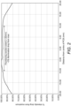
- Figure 2 shows the measured variation in intensity of the excitation radiation across the substrate 110. The arrow shows the extent of the substrate 110, at the edge of which the intensity drop from the maximum is 3 %.
- the variation in intensity of the excitation radiation 121 can be measured using a calibration substrate that is covered in a uniform fluorescing material.
- the variation in intensity of fluorescent radiation 122 is shown in Figure 3 , and is clearly larger than the variation in intensity of the excitation radiation 121.
- the intensity of fluorescent emission at the edge of the test substrate dimension is 8 % less than the maximum, however the variation is similar in shape to that of the excitation radiation 121, with a flat intensity across most of the substrate and dropping near to the edges.
- FIG. 4 A comparison of the intensity of the excitation radiation 121 at the substrate 110 and the intensity of the fluorescent emission of the calibration substrate is shown in Figure 4 .
- the arrow and dashed vertical lines indicate the edges of the test substrate 110.
- the solid curve 410 indicates the intensity of the excitation radiation 121
- the dashed curve 420 indicates the intensity of the fluorescent radiation 122. Both are flat at the central portion of the substrate, and drop off at the edges of the substrate.
- the intensity of the excitation radiation 121 drops by 3 % at the edge of the substrate and the intensity of the fluorescent emission drops by 8 % at the edge of the substrate.
- the beam splitter 140 and filters 150 and 160 are arranged to minimise the likelihood of radiation other than fluorescent radiation being incident on the sensor 130.
- the beam splitter 140 is arranged such that it transmits excitation radiation 121 from the electromagnetic radiation source 120 towards the substrate 110.
- the excitation radiation 121 excites the fluorescent material on the substrate 110, which emits fluorescent radiation 122 towards the beam splitter 140.
- the beam splitter 140 reflects the fluorescent radiation 122 towards the sensor 130.
- excitation radiation 121 is chosen to have a range of wavelengths that are centred away from the emission wavelength of the fluorescent material, the emission band of the electromagnetic radiation source 120 may overlap with the emission spectrum of the fluorescent material.
- the filters 150 and 160 are therefore an additional measure in seeking to minimise the likelihood of radiation other than fluorescent radiation reaching the sensor 130.
- the filter 150 limits transmission of electromagnetic radiation that has wavelengths close to the emission wavelengths of the fluorescent material.
- Filter 150 is positioned such that the electromagnetic radiation that is incident on the substrate 110 substantially excludes wavelengths that are similar to the wavelengths of the fluorescent emission. This means that light that is reflected from the substrate 110 and is incident on the beam splitter 140 will be transmitted and not reflected towards the sensor 130.
- Filter 160 is a narrow band pass filter 160 that has maximum transmission at the emission wavelength of the fluorescent material. Filter 160 is positioned between the beam splitter 140 and the sensor 130 to filter electromagnetic radiation 123, to further minimise the likelihood of radiation other than fluorescent radiation being incident on the sensor 130.
- Figure 5 shows, for an embodiment of the invention, the wavelengths of the emission radiation, the fluorescent radiation, as well as the wavelength of the filters.
- the electromagnetic radiation source 120 is a blue LED, with excitation radiation 121 having a band of wavelengths centred at 470 nm (solid line in Figure 5 ).
- the fluorescent material used in this embodiment has fluorescent radiation 122 centred at a wavelength of 520 nm.
- the beam splitter 140 (dash-dot line in Figure 5 ) is a dichroic filter that transmits electromagnetic radiation at wavelengths equal to or smaller than that of the excitation radiation 121 from the electromagnetic radiation source 120, and reflects electromagnetic radiation at wavelengths equal to or longer than the fluorescent radiation 122.
- the filter 150 that limits transmission of electromagnetic radiation with wavelengths close to the fluorescent emission is a short pass filter (long dashed line in Figure 5 ).
- the narrow band pass filter is centred at 520 nm (short dashed line in Figure 5 ).
- Figure 6 shows a test substrate to be imaged by a certain embodiment of the disclosure.
- the test substrate has a plurality of strips of fluorescent material.
- One of the plurality of strips may be a control strip while the remaining strips of the plurality of strips may be test strips, potentially with each test strip being for a different analyte.
- the test substrate may have dimensions 23 mm by 4.4 mm.
- the electromagnetic radiation source 120 is designed such that the excitation radiation 121 has a high degree of uniformity across the substrate 110.
- An embodiment in which the excitation radiation has very high uniformity may not have sufficient intensity of excitation radiation to excite the fluorescent material, so there is a compromise to be made between uniformity and mean intensity of the excitation radiation.
- the electromagnetic radiation source may be designed such that the excitation radiation 121 has a high degree of uniformity over the substrate 110 and has a mean intensity at the substrate 110 above a threshold.
- the electromagnetic radiation source 120 may comprise one or more LEDs. There may be two LEDs, with the spacing between the LEDs and distance to the substrate optimized to give maximum uniformity of intensity of excitation radiation across the substrate without dropping below a threshold of illumination efficiency.
- the LEDs may be blue LEDs with emission wavelengths centred at 570 nm.
- the LEDs may be placed 28 mm apart and 42 mm from the substrate, giving a calculated intensity variation across the substrate of 1.8 % and a measured intensity variation across the substrate of 3 %.
- a maximum and minimum threshold of mean intensity of excitation radiation 121 at the substrate 110 may be derived from calibration substrates.
- a threshold of uniformity of excitation radiation 121 at the substrate 110 may be derived from a calibration substrate.
- the senor 130 may comprise a CMOS sensor.
- the sensor 130 may comprise a plurality of sensing elements, with a total field of view covering the substrate 110.
- FIG. 7 An image processing method used to produce a value indicative of fluorescent emission from a substrate is indicated in Figure 7 .
- the substrate of which an image is taken is similar to that in Figure 5 , with a plurality of vertical strips of fluorescent material spaced horizontally across the substrate 110.
- a median filter is applied to remove any 'salt and pepper' noise, for example as caused by electronic noise or by dead pixels in the sensor.
- Figure 8A shows an image of a strip of fluorescent material before a median filter is applied, and Figure 8B shows the same image after the median filter has been applied.
- step 720 the endpoints of the strips of fluorescent material are found.
- the step is carried out for each column of pixels.
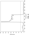
- Figure 9 shows an example of a plot of pixel intensity against vertical pixel index for a pixel column containing an image of a fluorescent strip.
- the threshold is shown as a dashed line.
- Calibration reference data stored in the device is used to modify the image.
- the calibration reference data is indicative of the variations in intensity of the excitation radiation, and may be derived from measurement of a calibration substrate that has a uniform fluorescent element.
- the test image is divided pixel-by-pixel by the calibration reference data.
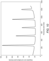
- the modified image is then used in step 730 to calculate a 1D trace of intensity. This is achieved by summing the pixel intensities along the columns of pixels, within the column endpoints defined in step 720. This integrated intensity is then plotted against the horizontal pixel index to give a 1D trace indicating the total intensity of each pixel column. This is shown plotted in Figure 10 .
- Test substrates such as that pictured in Figure 5 may have a control test strip at one end.
- the control strip is found by finding the pixel indices that have pixel intensities exceeding a threshold in the region where the control strip is expected to be found (this region is indicated by the box in Figure 11 , and the threshold is indicated as a dashed line).
- the average strip separation is known, so using the position of the control strip the positions of other strips can be calculated. Therefore regions of the 1D trace which are known to consist only of background signal can be found at the midpoints between the strips.
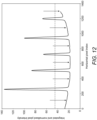
- the signal at the chosen background region can be integrated over a small window to find the background signal intensity at each background region. Arrows indicate the background regions in Figure 12 .
- a background trace, shown in Figure 13A is calculated by linear interpolation between consecutive background signal intensities and is indicative of residual non-uniformity in the excitation radiation. This background trace is subtracted from the 1D trace to obtain the corrected trace shown in Figure 13B . This occurs in step 750.
- the area of each peak gives the total fluorescence intensity in the corresponding strip of fluorescent material.
- the area is calculated in step 760 by sweeping a sliding window across the 1D trace, and integrating within the window.
- the width of the window should be approximately that of the strip of fluorescent material (and therefore approximately the width of a peak).
- the window is indicated in Figure 14A .
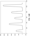
- the integrated pixel intensity is then plotted against the position of the centroid of the sliding window.
- the result is shown in Figure 14B .
- the height of each peak corresponds to the total fluorescence intensity of the corresponding strip of fluorescent material.
- the intensity of each strip is divided by that of the control strip to give a ratio. The ratio is compared to a threshold to determine whether the test is positive or negative for that particular analyte.
- the threshold values are known for each analyte and correspond to a particular quantity of the analyte.
- the analyte may be a metabolite that is indicative of a particular drug.
- the threshold is chosen to be the ratio which occurs for a certain dose of the drug. This is calculated using a drug calibration standard of known concentration, by depositing a quantity of metabolite indicative of the chosen dose onto the substrate, and calculating the ratio of the intensity of the fluorescent radiation of the test strip to the control strip. This threshold ratio is stored in the device, and in subsequent measurements the ratio of the intensity of the test strip to the control strip is compared to the threshold ratio.
- the threshold ratio is indicative of a certain known quantity of analyte.
- a positive result for the analyte indicates that it is present in larger quantities than in the calibration standard (as would be indicated by the threshold ratio), and a negative result indicates that it is present in smaller quantities than in the calibration standard.
- the device of this disclosure may be used to analyse fluorescent material on a substrate, wherein the fluorescent material binds to a particular analyte.
- This can be applied to drug detection if an analyte is indicative of the presence of a metabolite that results from drug use.
- a human intakes a substance (e.g. by ingestion, inhalation or injection) the substance may be metabolised by the human body giving rise to secondary substances known as metabolites.
- the presence of a particular metabolite can be indicative of a specific intake substance.
- the intake substance and/or metabolites may be present in sweat and, as such, may be left behind in a skin-print, e.g. a fingerprint. Detection of such metabolites in a skin-print can be used as a non-invasive method of testing for recent lifestyle activity such as (but not limited to) drug use, or compliance with a pharmaceutical or therapeutic treatment regime.
- the taking of a skin-print is much simpler than obtaining other body fluids such as blood, saliva and urine, and is more feasible in a wider range of situations. Not only this but since the appearance of the skin-print itself provides confirmation of the identity of the person providing the skin-print, there can be greater certainty that the substance or substances in the skin-print are associated with the individual. This is because substitution of a skin-print, particularly a fingerprint, is immediately identifiable from appearance whereas substitution of, for example, urine, is not immediately identifiable from appearance. As such, testing for one or more substances in a skin-print provides a direct link between the one or more substances and the identity of the human providing the skin-print.
- a substrate on which a skin-print is collected cannot be contaminated (either innocently or maliciously) before or after the impression of the skin is taken.
- the substrate must be accessible only for the short period during which the skin-print is taken.
- metabolite detection not only to be reliable but also to be simple, efficient and user-friendly.
- a volume of metabolite that, if present, might be expected in a fingerprint is likely to be of the order of microliters, it is desirable to maximise the proportion of the skin-print that is analysed in order to maximise accuracy of the test.
- Lateral flow device which receives a skin-print, and uses a buffer solution to draw the metabolites towards a test region.
- Lateral flow analysis is known in the art. Lateral flow immunoassays are simple tests for rapid detection of the presence or absence of a target analyte in a sample for home testing, point of care testing, or laboratory applications. Lateral flow devices preferably utilise a solid support through which a mobile phase (e.g., a buffer solution) can flow through by capillary action to a reaction matrix where a detectable signal, such as colour changes or colour differences at a test site, may be generated to indicate the presence or absence of the target analyte.
- a mobile phase e.g., a buffer solution
- a detectable signal such as colour changes or colour differences at a test site
- the lateral flow device described herein comprises a sample receiving portion for receiving a sample to be analysed; a solution capsule having a sealed configuration in which the solution capsule is sealed and a release configuration in which contents of the solution capsule are released via a flow path that provides fluid communication between the solution capsule and the sample receiving portion; and a bistable release mechanism comprising an actuator wherein the bistable release mechanism releases only in the event that a force applied to the actuator reaches a threshold force and wherein actuation of the actuator results in one-way conversion of the solution capsule from the sealed configuration into the release configuration.
- a skin-print most likely a fingerprint
- the analysing involves use of a solution
- the device comprising a first sample receiving portion comprising a wicking material for receiving a sample to be analysed using the solution; and a second sample receiving portion comprising a non-porous substrate.
- the lateral flow device as described herein is for use in an immunoassay i.e. a method for analysing a sample comprising above 0.1 pg of analyte.
- the immunoassay comprises a competitive binding assay, where any labelled probe (e.g. antibody) not bound to analyte provides an identifiable signal in the test site whilst any labelled probe bound to analyte, e.g. in the form of an immunocomplex, passes through the test site and does not provide an identifiable signal in the test site.
- any labelled probe e.g. antibody
- analyte e.g. in the form of an immunocomplex
- Such a device/method allows qualitative tests to be undertaken, i.e. whether or not the sample contains an analyte of interest. Such a device/method also may also allow quantitative tests to be undertaken by measuring the intensity of the signal at the test site, whereby the higher the intensity of the signal, the lower the amount of analyte in the sample.
- a solution is released in a controlled fashion onto a solution receiving region and is drawn (wicked) down a substrate towards a skin-print receiving region.
- the solution is selected to dissolve chemical species that may be present in the skin-print receiving region, such as an analyte of interest that may be present in a skin-print on the skin-print receiving region.
- the solution (which may or may not now include the analyte of interest) continues to be drawn down the substrate into an analysis region.
- the analysis region of the substrate may have a reduced width by comparison with the skin-print receiving region, to assist in concentrating the solution into a smaller area.
- the analysis region comprises a competitive binding assay having a label. If present, the analyte of interest will bind to the labelled assay.
- the label may comprise a fluorescent tag.
- the analysis region further comprises a result line.
- the result line comprises a further molecule, a protein-analyte conjugate, which is fixed in position (immobilised) on the substrate.
- the protein-analyte conjugate is chosen to bind with the assay in the event that the assay has not already been bound to the analyte of interest. Hence, if the analyte of interest is present, all available assay binding sites are occupied, the further molecule cannot bind with the assay and so the assay passes through. If, however, the analyte of interest is absent, the further molecule binds with the assay which is then fixed in position on the substrate. Since the assay is labelled, once sufficient assay is fixed in position, the label becomes apparent through, for example, a change in colour.
- the result line appears to change colour.
- the label may be fluorescent.
- the control line may be configured to capture a control assay that is present in the buffer solution. The purpose of the control line may be to show that the reaction conditions were as expected even when the result line does not change colour (indicating that an insufficient presence of the analyte of interest).
- the analysis region of the substrate may be quantitatively analysed using the device of this disclosure, which measures the total intensity of the fluorescent radiation emitted from each result line and the control line.
- the ratio of the intensity in a result line to the control line is compared to a threshold value to determine whether the analyte is present.
Landscapes
- Health & Medical Sciences (AREA)
- Life Sciences & Earth Sciences (AREA)
- Immunology (AREA)
- Chemical & Material Sciences (AREA)
- Physics & Mathematics (AREA)
- Engineering & Computer Science (AREA)
- Pathology (AREA)
- General Physics & Mathematics (AREA)
- General Health & Medical Sciences (AREA)
- Biochemistry (AREA)
- Molecular Biology (AREA)
- Analytical Chemistry (AREA)
- Hematology (AREA)
- Urology & Nephrology (AREA)
- Biomedical Technology (AREA)
- Medicinal Chemistry (AREA)
- Food Science & Technology (AREA)
- Microbiology (AREA)
- Cell Biology (AREA)
- Biotechnology (AREA)
- Nuclear Medicine, Radiotherapy & Molecular Imaging (AREA)
- Chemical Kinetics & Catalysis (AREA)
- Optics & Photonics (AREA)
- Theoretical Computer Science (AREA)
- Spectroscopy & Molecular Physics (AREA)
- Plasma & Fusion (AREA)
- Mathematical Physics (AREA)
- Investigating, Analyzing Materials By Fluorescence Or Luminescence (AREA)
- Inspection Of Paper Currency And Valuable Securities (AREA)
- Investigating Materials By The Use Of Optical Means Adapted For Particular Applications (AREA)
Claims (15)
- Dispositif (100) configuré pour fournir une valeur indicative d'une émission fluorescente d'un substrat (110) ayant une région d'essai comprenant une bandelette réactive et une bandelette de contrôle, le dispositif comprenant :a. une source de rayonnement électromagnétique (120) configurée pour émettre un rayonnement d'excitation (121) vers la région d'essai afin d'exciter l'émission fluorescente (122) d'un matériau fluorescent dans la région d'essai, la source de rayonnement électromagnétique (120) étant configurée de sorte qu'une variation d'intensité du rayonnement d'excitation dans la région d'essai est inférieure à 15% ; etb. un capteur (130) ayant un champ de vision couvrant la région d'essai et configuré pour capturer une image primaire de l'émission fluorescente (122), dans laquelle l'image primaire comprend une pluralité de colonnes de pixels chacune à un indice de pixel horizontal ; etc. un dispositif de commande configuré :caractérisé en ce que le dispositif de commande est en outre configuré :i. pour modifier l'image primaire sur la base de données d'étalonnage indicatives des variations d'intensité du rayonnement d'excitation (121) afin de produire une image modifiée ;
ii. pour utiliser l'image modifiée afin d'obtenir la valeur indicative de l'émission fluorescente (122) :en additionnant les intensités de pixels de chaque colonne de pixels de l'image modifiée afin d'obtenir une trace de l'intensité totale par rapport à l'indice de pixel horizontal ;pour une région d'indices de pixels horizontaux comprenant la bandelette de contrôle, en comparant l'intensité totale à chaque indice de pixel horizontal à une valeur seuil et en définissant la position de la bandelette de contrôle en tant que les indices de pixels horizontaux correspondant à des intensités totales dépassant un seuil ;en utilisant la position de la bandelette de contrôle et une séparation de bandelettes connue entre la bandelette de contrôle et la bandelette réactive pour trouver des régions aux points médians entre les bandelettes correspondant à une pluralité d'indices de pixels horizontaux comprenant des signaux de fond, et en intégrant le signal au niveau des régions de fond choisies sur une petite fenêtre afin de trouver l'intensité du signal de fond au niveau de chaque région de fond, et en interpolant linéairement entre les intensités totales des signaux de fond pour générer une trace de fond ; eten obtenant une trace corrigée en soustrayant la trace de fond de la trace d'intensité. - Dispositif de la revendication 1, comprenant en outre un séparateur de faisceau (140) qui transmet le rayonnement d'excitation (121) émis par la source de rayonnement électromagnétique (120) et réfléchit l'émission fluorescente (122), et comprenant éventuellement un ou les deux entre :un filtre passe-bande étroit centré sur la longueur d'onde de l'émission fluorescente ; etun filtre (150) qui limite la transmission du rayonnement électromagnétique qui présente une gamme de longueurs d'onde qui chevauche les longueurs d'onde de l'émission fluorescente (122).
- Dispositif de la revendication 1, dans lequel la variation d'intensité du rayonnement d'excitation dans la région d'essai est inférieure à 5%, ou plus préférablement inférieure à 4%, ou plus préférablement inférieure à 3%, ou encore plus préférablement inférieure à 2%.
- Dispositif de la revendication 1, dans lequel le rayonnement d'excitation dans la région d'essai est supérieur à un seuil d'intensité.
- Dispositif de la revendication 1, dans lequel le dispositif de commande est configuré pour corriger les non-uniformités dans le champ d'illumination en divisant l'image mesurée pixel par pixel par les données de référence d'étalonnage.
- Dispositif de la revendication 1, dans lequel le dispositif de commande est en outre configuré pour obtenir une première valeur indicative de l'émission fluorescente de la bandelette réactive et une seconde valeur indicative de l'émission fluorescente de la bandelette de contrôle, et pour diviser la première valeur par la seconde valeur afin de fournir un rapport, et dans lequel, éventuellement, le rapport est comparé à une valeur seuil.
- Dispositif de la revendication 6, dans lequel la bandelette réactive est l'une d'une pluralité de bandelettes réactives.
- Dispositif de la revendication 1, dans lequel les données d'étalonnage sont dérivées de la mesure de l'émission fluorescente d'un substrat d'étalonnage et sont indicatives de la variation d'intensité du rayonnement d'excitation provenant de la source de rayonnement électromagnétique.
- Dispositif de la revendication 8, comprend en outre un substrat d'étalonnage avec un élément fluorescent uniforme dont l'émission spectrale se situe dans une gamme de longueurs d'onde qui présente un degré élevé de chevauchement avec la gamme de longueurs d'onde émises par la substance fluorescente sur la région d'essai du substrat.
- Dispositif de la revendication 1, dans lequel :le capteur comprend un capteur CMOS ; et/oula source lumineuse comprend un ou plusieurs entre :deux LED ; etdes LED bleues.
- Procédé permettant d'obtenir une valeur indicative d'une émission fluorescente (122) d'un substrat (110) ayant une région d'essai comprenant une bandelette réactive et une bandelette de contrôle, le procédé comprenant les étapes consistant à :a. exciter l'émission fluorescente (122) d'un matériau fluorescent dans la région d'essai avec un rayonnement d'excitation (121), dans laquelle la variation d'intensité du rayonnement d'excitation dans la région d'essai est inférieure à 15% ;b. capturer une image primaire de la région d'essai avec un capteur configuré pour présenter un champ de vision couvrant la région d'essai, dans laquelle l'image primaire comprend une pluralité de colonnes de pixels chacune à un indice de pixel horizontal ; etc. modifier l'image primaire sur la base de données d'étalonnage indicatives des variations d'intensité du rayonnement d'excitation afin de produire une image modifiée ;caractérisé en ce que le procédé comprend en outre l'étape consistant à :
d. utiliser l'image modifiée afin d'obtenir la valeur indicative de l'émission fluorescente (122) de la région d'essai :en additionnant les intensités de pixels de chaque colonne de pixels de l'image modifiée afin d'obtenir une trace de l'intensité totale par rapport à l'indice de pixel horizontal ;pour une région d'indices de pixels horizontaux comprenant la bandelette de contrôle, en comparant l'intensité totale à chaque indice de pixel horizontal à une valeur seuil et en définissant la position de la bandelette de contrôle en tant que les indices de pixels horizontaux correspondant à des intensités totales dépassant un seuil ;en utilisant la position de la bandelette de contrôle et une séparation de bandelettes connue entre la bandelette de contrôle et la bandelette réactive pour trouver des régions aux points médians entre les bandelettes correspondant à une pluralité d'indices de pixels horizontaux comprenant des signaux de fond, et en intégrant le signal au niveau des régions de fond choisies sur une petite fenêtre afin de trouver l'intensité du signal de fond au niveau de chaque région de fond, et en interpolant linéairement entre les intensités totales des signaux de fond pour générer une trace de fond ; eten obtenant une trace corrigée en soustrayant la trace de fond de la trace d'intensité. - Procédé de la revendication 11, dans lequel des filtres éliminent le rayonnement électromagnétique, qui n'est pas émis par le matériau fluorescent, du rayonnement électromagnétique incident sur le capteur.
- Procédé de la revendication 11, dans lequel le matériau fluorescent est excité par un rayonnement d'excitation qui présente une variation d'intensité dans la région d'essai qui est inférieure à 5%.
- Procédé de la revendication 11, dans lequel les données concernant l'émission fluorescente d'un substrat sont obtenues pour une région d'essai comprenant une bandelette de contrôle et une ou plusieurs bandelettes réactives.
- Procédé de la revendication 11, dans lequel les données de référence d'étalonnage sont dérivées d'une mesure d'un substrat d'étalonnage.
Applications Claiming Priority (2)
| Application Number | Priority Date | Filing Date | Title |
|---|---|---|---|
| GB2002859.3A GB2592432B (en) | 2020-02-28 | 2020-02-28 | Reader for analysing fluorescent markers |
| PCT/GB2021/050483 WO2021171023A1 (fr) | 2020-02-28 | 2021-02-25 | Lecteur permettant d'analyser des marqueurs fluorescents |
Publications (3)
| Publication Number | Publication Date |
|---|---|
| EP4111173A1 EP4111173A1 (fr) | 2023-01-04 |
| EP4111173B1 true EP4111173B1 (fr) | 2024-01-31 |
| EP4111173C0 EP4111173C0 (fr) | 2024-01-31 |
Family
ID=70278741
Family Applications (1)
| Application Number | Title | Priority Date | Filing Date |
|---|---|---|---|
| EP21709774.0A Active EP4111173B1 (fr) | 2020-02-28 | 2021-02-25 | Lecteur permettant d'analyser des marqueurs fluorescents |
Country Status (5)
| Country | Link |
|---|---|
| US (1) | US12523614B2 (fr) |
| EP (1) | EP4111173B1 (fr) |
| AU (1) | AU2021225394A1 (fr) |
| GB (1) | GB2592432B (fr) |
| WO (1) | WO2021171023A1 (fr) |
Families Citing this family (1)
| Publication number | Priority date | Publication date | Assignee | Title |
|---|---|---|---|---|
| JP2025186051A (ja) * | 2024-06-11 | 2025-12-23 | アークレイ株式会社 | 判定システム、試験片及び蛍光基準片 |
Family Cites Families (12)
| Publication number | Priority date | Publication date | Assignee | Title |
|---|---|---|---|---|
| US7796266B2 (en) * | 2004-04-30 | 2010-09-14 | Kimberly-Clark Worldwide, Inc. | Optical detection system using electromagnetic radiation to detect presence or quantity of analyte |
| US7477931B2 (en) * | 2004-12-06 | 2009-01-13 | Cambridge Research & Instruments, Inc. | Systems and methods for in-vivo and optical imaging and measurement |
| WO2007134189A2 (fr) * | 2006-05-10 | 2007-11-22 | Board Of Regents, The University Of Texas System | Détection de biomarqueurs tumoraux dans le cancer de la bouche |
| US20160370366A1 (en) * | 2010-07-20 | 2016-12-22 | Quantrx Biomedical Corporation | Optical reader systems and lateral flow assays |
| WO2012012499A1 (fr) * | 2010-07-20 | 2012-01-26 | Nurx Pharmaceuticals, Inc. | Système de lecteur optique |
| WO2013096817A2 (fr) * | 2011-12-23 | 2013-06-27 | Abbott Point Of Care Inc | Dispositif d'essai intégré pour détection optique de microréseaux |
| JP6392785B2 (ja) * | 2013-01-31 | 2018-09-19 | ベンタナ メディカル システムズ, インコーポレイテッド | 多重組織検定用の撮像デバイスまたはシステムを較正、構成、および有効性判断するためのシステムおよび方法 |
| WO2014172269A2 (fr) * | 2013-04-18 | 2014-10-23 | Bio-Rad Laboratories, Inc. | Dispositif de formation d'image de fluorescence sur un dispositif mobile |
| EP3230718B1 (fr) * | 2014-12-09 | 2022-03-02 | Berkeley Lights, Inc. | Détection automatisée de zones d'analyse positives ou de quantités d'analytes dans des dispositifs microfluidiques |
| GB2535998A (en) | 2015-02-27 | 2016-09-07 | Intelligent Fingerprinting Ltd | A device for receiving and analysing a sample |
| CN118329854A (zh) * | 2015-10-15 | 2024-07-12 | 卢莫斯诊断Ip股份有限公司 | 用于读出ivd测定的装置 |
| GB201610988D0 (en) * | 2016-06-23 | 2016-08-10 | Inspection Tech Ltd | Apparatus and method for extracting low intensity photonic signals |
-
2020
- 2020-02-28 GB GB2002859.3A patent/GB2592432B/en active Active
-
2021
- 2021-02-25 AU AU2021225394A patent/AU2021225394A1/en active Pending
- 2021-02-25 US US17/904,887 patent/US12523614B2/en active Active
- 2021-02-25 EP EP21709774.0A patent/EP4111173B1/fr active Active
- 2021-02-25 WO PCT/GB2021/050483 patent/WO2021171023A1/fr not_active Ceased
Also Published As
| Publication number | Publication date |
|---|---|
| GB2592432B (en) | 2023-04-12 |
| GB202002859D0 (en) | 2020-04-15 |
| EP4111173A1 (fr) | 2023-01-04 |
| EP4111173C0 (fr) | 2024-01-31 |
| WO2021171023A1 (fr) | 2021-09-02 |
| US20230087664A1 (en) | 2023-03-23 |
| GB2592432A (en) | 2021-09-01 |
| AU2021225394A1 (en) | 2022-09-08 |
| US12523614B2 (en) | 2026-01-13 |
Similar Documents
| Publication | Publication Date | Title |
|---|---|---|
| US11953428B2 (en) | Method for reducing analyzer variability using a normalization target | |
| US10690664B2 (en) | Optical assay device with pneumatic sample actuation | |
| CN104081207B (zh) | 用于光学和电化学测定的检验装置 | |
| US10451615B2 (en) | Methods and devices for performing high dynamic range immunoassays | |
| JP5480263B2 (ja) | 符号化認識を有する分析システム | |
| US9733063B2 (en) | Method and device for determining optical properties by simultaneous measurement of intensities at thin layers using light of several wavelengths | |
| WO2013096801A1 (fr) | Dispositifs de lecteur pour dispositifs d'essai optiques et électrochimiques | |
| KR102652419B1 (ko) | 생물학적 샘플에서 분석물 및/또는 단백질을 측정하기 위한 방법 | |
| JP2022506376A (ja) | 分析測定を実行するための方法および装置 | |
| US11719700B2 (en) | Upconversion for microscopy | |
| US11668711B2 (en) | Multiplexed diagnostic assay for iron and vitamin A deficiency and methods of use thereof | |
| EP1775577A1 (fr) | Appareil de balayage et d'analyse portable | |
| EP4111173B1 (fr) | Lecteur permettant d'analyser des marqueurs fluorescents | |
| EP3724642A1 (fr) | Dispositif de préparation, appareil de diagnostic, kit de diagnostic et système de diagnostic | |
| US7264971B2 (en) | Read-head for optical diagnostic device | |
| KR102393593B1 (ko) | 체외 진단 스트립 측정용 형광 리더기 | |
| JP2000507353A (ja) | テスト要素用定量的分析評価システム | |
| JP6011246B2 (ja) | 蛍光測定方法、蛍光測定キット及び蛍光光度計 | |
| Pichayawaytin et al. | A method and optical references for compensating signal drift in a fluorescent microarray reader | |
| RU2824292C2 (ru) | Способ определения концентрации аналита в физиологической жидкости | |
| JP2025186051A (ja) | 判定システム、試験片及び蛍光基準片 | |
| JP2020139823A (ja) | 分子の測定方法、肌状態の診断方法、及び、分子の測定装置 |
Legal Events
| Date | Code | Title | Description |
|---|---|---|---|
| STAA | Information on the status of an ep patent application or granted ep patent |
Free format text: STATUS: UNKNOWN |
|
| STAA | Information on the status of an ep patent application or granted ep patent |
Free format text: STATUS: THE INTERNATIONAL PUBLICATION HAS BEEN MADE |
|
| PUAI | Public reference made under article 153(3) epc to a published international application that has entered the european phase |
Free format text: ORIGINAL CODE: 0009012 |
|
| STAA | Information on the status of an ep patent application or granted ep patent |
Free format text: STATUS: REQUEST FOR EXAMINATION WAS MADE |
|
| 17P | Request for examination filed |
Effective date: 20220927 |
|
| AK | Designated contracting states |
Kind code of ref document: A1 Designated state(s): AL AT BE BG CH CY CZ DE DK EE ES FI FR GB GR HR HU IE IS IT LI LT LU LV MC MK MT NL NO PL PT RO RS SE SI SK SM TR |
|
| DAV | Request for validation of the european patent (deleted) | ||
| DAX | Request for extension of the european patent (deleted) | ||
| GRAP | Despatch of communication of intention to grant a patent |
Free format text: ORIGINAL CODE: EPIDOSNIGR1 |
|
| STAA | Information on the status of an ep patent application or granted ep patent |
Free format text: STATUS: GRANT OF PATENT IS INTENDED |
|
| INTG | Intention to grant announced |
Effective date: 20230828 |
|
| GRAS | Grant fee paid |
Free format text: ORIGINAL CODE: EPIDOSNIGR3 |
|
| GRAA | (expected) grant |
Free format text: ORIGINAL CODE: 0009210 |
|
| STAA | Information on the status of an ep patent application or granted ep patent |
Free format text: STATUS: THE PATENT HAS BEEN GRANTED |
|
| AK | Designated contracting states |
Kind code of ref document: B1 Designated state(s): AL AT BE BG CH CY CZ DE DK EE ES FI FR GB GR HR HU IE IS IT LI LT LU LV MC MK MT NL NO PL PT RO RS SE SI SK SM TR |
|
| REG | Reference to a national code |
Ref country code: GB Ref legal event code: FG4D Ref country code: CH Ref legal event code: EP |
|
| REG | Reference to a national code |
Ref country code: DE Ref legal event code: R096 Ref document number: 602021009002 Country of ref document: DE |
|
| REG | Reference to a national code |
Ref country code: IE Ref legal event code: FG4D |
|
| U01 | Request for unitary effect filed |
Effective date: 20240220 |
|
| U07 | Unitary effect registered |
Designated state(s): AT BE BG DE DK EE FI FR IT LT LU LV MT NL PT SE SI Effective date: 20240229 |
|
| REG | Reference to a national code |
Ref country code: LT Ref legal event code: MG9D |
|
| U20 | Renewal fee for the european patent with unitary effect paid |
Year of fee payment: 4 Effective date: 20240516 |
|
| PG25 | Lapsed in a contracting state [announced via postgrant information from national office to epo] |
Ref country code: IS Free format text: LAPSE BECAUSE OF FAILURE TO SUBMIT A TRANSLATION OF THE DESCRIPTION OR TO PAY THE FEE WITHIN THE PRESCRIBED TIME-LIMIT Effective date: 20240531 |
|
| PG25 | Lapsed in a contracting state [announced via postgrant information from national office to epo] |
Ref country code: GR Free format text: LAPSE BECAUSE OF FAILURE TO SUBMIT A TRANSLATION OF THE DESCRIPTION OR TO PAY THE FEE WITHIN THE PRESCRIBED TIME-LIMIT Effective date: 20240501 |
|
| PG25 | Lapsed in a contracting state [announced via postgrant information from national office to epo] |
Ref country code: HR Free format text: LAPSE BECAUSE OF FAILURE TO SUBMIT A TRANSLATION OF THE DESCRIPTION OR TO PAY THE FEE WITHIN THE PRESCRIBED TIME-LIMIT Effective date: 20240131 Ref country code: RS Free format text: LAPSE BECAUSE OF FAILURE TO SUBMIT A TRANSLATION OF THE DESCRIPTION OR TO PAY THE FEE WITHIN THE PRESCRIBED TIME-LIMIT Effective date: 20240430 |
|
| PG25 | Lapsed in a contracting state [announced via postgrant information from national office to epo] |
Ref country code: ES Free format text: LAPSE BECAUSE OF FAILURE TO SUBMIT A TRANSLATION OF THE DESCRIPTION OR TO PAY THE FEE WITHIN THE PRESCRIBED TIME-LIMIT Effective date: 20240131 |
|
| PG25 | Lapsed in a contracting state [announced via postgrant information from national office to epo] |
Ref country code: RS Free format text: LAPSE BECAUSE OF FAILURE TO SUBMIT A TRANSLATION OF THE DESCRIPTION OR TO PAY THE FEE WITHIN THE PRESCRIBED TIME-LIMIT Effective date: 20240430 Ref country code: NO Free format text: LAPSE BECAUSE OF FAILURE TO SUBMIT A TRANSLATION OF THE DESCRIPTION OR TO PAY THE FEE WITHIN THE PRESCRIBED TIME-LIMIT Effective date: 20240430 Ref country code: IS Free format text: LAPSE BECAUSE OF FAILURE TO SUBMIT A TRANSLATION OF THE DESCRIPTION OR TO PAY THE FEE WITHIN THE PRESCRIBED TIME-LIMIT Effective date: 20240531 Ref country code: HR Free format text: LAPSE BECAUSE OF FAILURE TO SUBMIT A TRANSLATION OF THE DESCRIPTION OR TO PAY THE FEE WITHIN THE PRESCRIBED TIME-LIMIT Effective date: 20240131 Ref country code: GR Free format text: LAPSE BECAUSE OF FAILURE TO SUBMIT A TRANSLATION OF THE DESCRIPTION OR TO PAY THE FEE WITHIN THE PRESCRIBED TIME-LIMIT Effective date: 20240501 Ref country code: ES Free format text: LAPSE BECAUSE OF FAILURE TO SUBMIT A TRANSLATION OF THE DESCRIPTION OR TO PAY THE FEE WITHIN THE PRESCRIBED TIME-LIMIT Effective date: 20240131 |
|
| PG25 | Lapsed in a contracting state [announced via postgrant information from national office to epo] |
Ref country code: PL Free format text: LAPSE BECAUSE OF FAILURE TO SUBMIT A TRANSLATION OF THE DESCRIPTION OR TO PAY THE FEE WITHIN THE PRESCRIBED TIME-LIMIT Effective date: 20240131 |
|
| PG25 | Lapsed in a contracting state [announced via postgrant information from national office to epo] |
Ref country code: PL Free format text: LAPSE BECAUSE OF FAILURE TO SUBMIT A TRANSLATION OF THE DESCRIPTION OR TO PAY THE FEE WITHIN THE PRESCRIBED TIME-LIMIT Effective date: 20240131 |
|
| REG | Reference to a national code |
Ref country code: CH Ref legal event code: PL |
|
| PG25 | Lapsed in a contracting state [announced via postgrant information from national office to epo] |
Ref country code: SM Free format text: LAPSE BECAUSE OF FAILURE TO SUBMIT A TRANSLATION OF THE DESCRIPTION OR TO PAY THE FEE WITHIN THE PRESCRIBED TIME-LIMIT Effective date: 20240131 |
|
| PG25 | Lapsed in a contracting state [announced via postgrant information from national office to epo] |
Ref country code: CH Free format text: LAPSE BECAUSE OF NON-PAYMENT OF DUE FEES Effective date: 20240229 |
|
| PG25 | Lapsed in a contracting state [announced via postgrant information from national office to epo] |
Ref country code: CZ Free format text: LAPSE BECAUSE OF FAILURE TO SUBMIT A TRANSLATION OF THE DESCRIPTION OR TO PAY THE FEE WITHIN THE PRESCRIBED TIME-LIMIT Effective date: 20240131 |
|
| PG25 | Lapsed in a contracting state [announced via postgrant information from national office to epo] |
Ref country code: SK Free format text: LAPSE BECAUSE OF FAILURE TO SUBMIT A TRANSLATION OF THE DESCRIPTION OR TO PAY THE FEE WITHIN THE PRESCRIBED TIME-LIMIT Effective date: 20240131 |
|
| PG25 | Lapsed in a contracting state [announced via postgrant information from national office to epo] |
Ref country code: SM Free format text: LAPSE BECAUSE OF FAILURE TO SUBMIT A TRANSLATION OF THE DESCRIPTION OR TO PAY THE FEE WITHIN THE PRESCRIBED TIME-LIMIT Effective date: 20240131 Ref country code: SK Free format text: LAPSE BECAUSE OF FAILURE TO SUBMIT A TRANSLATION OF THE DESCRIPTION OR TO PAY THE FEE WITHIN THE PRESCRIBED TIME-LIMIT Effective date: 20240131 Ref country code: RO Free format text: LAPSE BECAUSE OF FAILURE TO SUBMIT A TRANSLATION OF THE DESCRIPTION OR TO PAY THE FEE WITHIN THE PRESCRIBED TIME-LIMIT Effective date: 20240131 Ref country code: CZ Free format text: LAPSE BECAUSE OF FAILURE TO SUBMIT A TRANSLATION OF THE DESCRIPTION OR TO PAY THE FEE WITHIN THE PRESCRIBED TIME-LIMIT Effective date: 20240131 Ref country code: CH Free format text: LAPSE BECAUSE OF NON-PAYMENT OF DUE FEES Effective date: 20240229 |
|
| REG | Reference to a national code |
Ref country code: DE Ref legal event code: R097 Ref document number: 602021009002 Country of ref document: DE |
|
| PG25 | Lapsed in a contracting state [announced via postgrant information from national office to epo] |
Ref country code: MC Free format text: LAPSE BECAUSE OF FAILURE TO SUBMIT A TRANSLATION OF THE DESCRIPTION OR TO PAY THE FEE WITHIN THE PRESCRIBED TIME-LIMIT Effective date: 20240131 |
|
| PG25 | Lapsed in a contracting state [announced via postgrant information from national office to epo] |
Ref country code: MC Free format text: LAPSE BECAUSE OF FAILURE TO SUBMIT A TRANSLATION OF THE DESCRIPTION OR TO PAY THE FEE WITHIN THE PRESCRIBED TIME-LIMIT Effective date: 20240131 |
|
| PLBE | No opposition filed within time limit |
Free format text: ORIGINAL CODE: 0009261 |
|
| STAA | Information on the status of an ep patent application or granted ep patent |
Free format text: STATUS: NO OPPOSITION FILED WITHIN TIME LIMIT |
|
| 26N | No opposition filed |
Effective date: 20241101 |
|
| PG25 | Lapsed in a contracting state [announced via postgrant information from national office to epo] |
Ref country code: IE Free format text: LAPSE BECAUSE OF NON-PAYMENT OF DUE FEES Effective date: 20240225 |
|
| PG25 | Lapsed in a contracting state [announced via postgrant information from national office to epo] |
Ref country code: IE Free format text: LAPSE BECAUSE OF NON-PAYMENT OF DUE FEES Effective date: 20240225 |
|
| U20 | Renewal fee for the european patent with unitary effect paid |
Year of fee payment: 5 Effective date: 20250217 |
|
| PG25 | Lapsed in a contracting state [announced via postgrant information from national office to epo] |
Ref country code: CY Free format text: LAPSE BECAUSE OF FAILURE TO SUBMIT A TRANSLATION OF THE DESCRIPTION OR TO PAY THE FEE WITHIN THE PRESCRIBED TIME-LIMIT; INVALID AB INITIO Effective date: 20210225 |
|
| PG25 | Lapsed in a contracting state [announced via postgrant information from national office to epo] |
Ref country code: HU Free format text: LAPSE BECAUSE OF FAILURE TO SUBMIT A TRANSLATION OF THE DESCRIPTION OR TO PAY THE FEE WITHIN THE PRESCRIBED TIME-LIMIT; INVALID AB INITIO Effective date: 20210225 |
|
| PG25 | Lapsed in a contracting state [announced via postgrant information from national office to epo] |
Ref country code: TR Free format text: LAPSE BECAUSE OF FAILURE TO SUBMIT A TRANSLATION OF THE DESCRIPTION OR TO PAY THE FEE WITHIN THE PRESCRIBED TIME-LIMIT Effective date: 20240131 |
|
| U20 | Renewal fee for the european patent with unitary effect paid |
Year of fee payment: 6 Effective date: 20260216 |
|
| PGFP | Annual fee paid to national office [announced via postgrant information from national office to epo] |
Ref country code: GB Payment date: 20260216 Year of fee payment: 6 |