EP4112010B1 - Knieprothese - Google Patents
Knieprothese Download PDFInfo
- Publication number
- EP4112010B1 EP4112010B1 EP20920892.5A EP20920892A EP4112010B1 EP 4112010 B1 EP4112010 B1 EP 4112010B1 EP 20920892 A EP20920892 A EP 20920892A EP 4112010 B1 EP4112010 B1 EP 4112010B1
- Authority
- EP
- European Patent Office
- Prior art keywords
- spacer
- medial
- lateral
- condyle
- tibial plateau
- Prior art date
- Legal status (The legal status is an assumption and is not a legal conclusion. Google has not performed a legal analysis and makes no representation as to the accuracy of the status listed.)
- Active
Links
Images





Classifications
-
- A—HUMAN NECESSITIES
- A61—MEDICAL OR VETERINARY SCIENCE; HYGIENE
- A61F—FILTERS IMPLANTABLE INTO BLOOD VESSELS; PROSTHESES; DEVICES PROVIDING PATENCY TO, OR PREVENTING COLLAPSING OF, TUBULAR STRUCTURES OF THE BODY, e.g. STENTS; ORTHOPAEDIC, NURSING OR CONTRACEPTIVE DEVICES; FOMENTATION; TREATMENT OR PROTECTION OF EYES OR EARS; BANDAGES, DRESSINGS OR ABSORBENT PADS; FIRST-AID KITS
- A61F2/00—Filters implantable into blood vessels; Prostheses, i.e. artificial substitutes or replacements for parts of the body; Appliances for connecting them with the body; Devices providing patency to, or preventing collapsing of, tubular structures of the body, e.g. stents
- A61F2/02—Prostheses implantable into the body
- A61F2/30—Joints
- A61F2/38—Joints for elbows or knees
-
- A—HUMAN NECESSITIES
- A61—MEDICAL OR VETERINARY SCIENCE; HYGIENE
- A61F—FILTERS IMPLANTABLE INTO BLOOD VESSELS; PROSTHESES; DEVICES PROVIDING PATENCY TO, OR PREVENTING COLLAPSING OF, TUBULAR STRUCTURES OF THE BODY, e.g. STENTS; ORTHOPAEDIC, NURSING OR CONTRACEPTIVE DEVICES; FOMENTATION; TREATMENT OR PROTECTION OF EYES OR EARS; BANDAGES, DRESSINGS OR ABSORBENT PADS; FIRST-AID KITS
- A61F2/00—Filters implantable into blood vessels; Prostheses, i.e. artificial substitutes or replacements for parts of the body; Appliances for connecting them with the body; Devices providing patency to, or preventing collapsing of, tubular structures of the body, e.g. stents
- A61F2/02—Prostheses implantable into the body
- A61F2/30—Joints
- A61F2/38—Joints for elbows or knees
- A61F2/3859—Femoral components
-
- A—HUMAN NECESSITIES
- A61—MEDICAL OR VETERINARY SCIENCE; HYGIENE
- A61F—FILTERS IMPLANTABLE INTO BLOOD VESSELS; PROSTHESES; DEVICES PROVIDING PATENCY TO, OR PREVENTING COLLAPSING OF, TUBULAR STRUCTURES OF THE BODY, e.g. STENTS; ORTHOPAEDIC, NURSING OR CONTRACEPTIVE DEVICES; FOMENTATION; TREATMENT OR PROTECTION OF EYES OR EARS; BANDAGES, DRESSINGS OR ABSORBENT PADS; FIRST-AID KITS
- A61F2/00—Filters implantable into blood vessels; Prostheses, i.e. artificial substitutes or replacements for parts of the body; Appliances for connecting them with the body; Devices providing patency to, or preventing collapsing of, tubular structures of the body, e.g. stents
- A61F2/02—Prostheses implantable into the body
- A61F2/30—Joints
- A61F2/38—Joints for elbows or knees
- A61F2/3868—Joints for elbows or knees with sliding tibial bearing
-
- A—HUMAN NECESSITIES
- A61—MEDICAL OR VETERINARY SCIENCE; HYGIENE
- A61F—FILTERS IMPLANTABLE INTO BLOOD VESSELS; PROSTHESES; DEVICES PROVIDING PATENCY TO, OR PREVENTING COLLAPSING OF, TUBULAR STRUCTURES OF THE BODY, e.g. STENTS; ORTHOPAEDIC, NURSING OR CONTRACEPTIVE DEVICES; FOMENTATION; TREATMENT OR PROTECTION OF EYES OR EARS; BANDAGES, DRESSINGS OR ABSORBENT PADS; FIRST-AID KITS
- A61F2/00—Filters implantable into blood vessels; Prostheses, i.e. artificial substitutes or replacements for parts of the body; Appliances for connecting them with the body; Devices providing patency to, or preventing collapsing of, tubular structures of the body, e.g. stents
- A61F2/02—Prostheses implantable into the body
- A61F2/30—Joints
- A61F2/38—Joints for elbows or knees
- A61F2/389—Tibial components
-
- A—HUMAN NECESSITIES
- A61—MEDICAL OR VETERINARY SCIENCE; HYGIENE
- A61F—FILTERS IMPLANTABLE INTO BLOOD VESSELS; PROSTHESES; DEVICES PROVIDING PATENCY TO, OR PREVENTING COLLAPSING OF, TUBULAR STRUCTURES OF THE BODY, e.g. STENTS; ORTHOPAEDIC, NURSING OR CONTRACEPTIVE DEVICES; FOMENTATION; TREATMENT OR PROTECTION OF EYES OR EARS; BANDAGES, DRESSINGS OR ABSORBENT PADS; FIRST-AID KITS
- A61F2/00—Filters implantable into blood vessels; Prostheses, i.e. artificial substitutes or replacements for parts of the body; Appliances for connecting them with the body; Devices providing patency to, or preventing collapsing of, tubular structures of the body, e.g. stents
- A61F2/02—Prostheses implantable into the body
- A61F2/30—Joints
- A61F2002/30001—Additional features of subject-matter classified in A61F2/28, A61F2/30 and subgroups thereof
- A61F2002/30316—The prosthesis having different structural features at different locations within the same prosthesis; Connections between prosthetic parts; Special structural features of bone or joint prostheses not otherwise provided for
- A61F2002/30329—Connections or couplings between prosthetic parts, e.g. between modular parts; Connecting elements
- A61F2002/30518—Connections or couplings between prosthetic parts, e.g. between modular parts; Connecting elements with possibility of relative movement between the prosthetic parts
-
- A—HUMAN NECESSITIES
- A61—MEDICAL OR VETERINARY SCIENCE; HYGIENE
- A61F—FILTERS IMPLANTABLE INTO BLOOD VESSELS; PROSTHESES; DEVICES PROVIDING PATENCY TO, OR PREVENTING COLLAPSING OF, TUBULAR STRUCTURES OF THE BODY, e.g. STENTS; ORTHOPAEDIC, NURSING OR CONTRACEPTIVE DEVICES; FOMENTATION; TREATMENT OR PROTECTION OF EYES OR EARS; BANDAGES, DRESSINGS OR ABSORBENT PADS; FIRST-AID KITS
- A61F2/00—Filters implantable into blood vessels; Prostheses, i.e. artificial substitutes or replacements for parts of the body; Appliances for connecting them with the body; Devices providing patency to, or preventing collapsing of, tubular structures of the body, e.g. stents
- A61F2/02—Prostheses implantable into the body
- A61F2/30—Joints
- A61F2002/30001—Additional features of subject-matter classified in A61F2/28, A61F2/30 and subgroups thereof
- A61F2002/30316—The prosthesis having different structural features at different locations within the same prosthesis; Connections between prosthetic parts; Special structural features of bone or joint prostheses not otherwise provided for
- A61F2002/30329—Connections or couplings between prosthetic parts, e.g. between modular parts; Connecting elements
- A61F2002/30518—Connections or couplings between prosthetic parts, e.g. between modular parts; Connecting elements with possibility of relative movement between the prosthetic parts
- A61F2002/30528—Means for limiting said movement
-
- A—HUMAN NECESSITIES
- A61—MEDICAL OR VETERINARY SCIENCE; HYGIENE
- A61F—FILTERS IMPLANTABLE INTO BLOOD VESSELS; PROSTHESES; DEVICES PROVIDING PATENCY TO, OR PREVENTING COLLAPSING OF, TUBULAR STRUCTURES OF THE BODY, e.g. STENTS; ORTHOPAEDIC, NURSING OR CONTRACEPTIVE DEVICES; FOMENTATION; TREATMENT OR PROTECTION OF EYES OR EARS; BANDAGES, DRESSINGS OR ABSORBENT PADS; FIRST-AID KITS
- A61F2/00—Filters implantable into blood vessels; Prostheses, i.e. artificial substitutes or replacements for parts of the body; Appliances for connecting them with the body; Devices providing patency to, or preventing collapsing of, tubular structures of the body, e.g. stents
- A61F2/02—Prostheses implantable into the body
- A61F2/30—Joints
- A61F2002/30001—Additional features of subject-matter classified in A61F2/28, A61F2/30 and subgroups thereof
- A61F2002/30316—The prosthesis having different structural features at different locations within the same prosthesis; Connections between prosthetic parts; Special structural features of bone or joint prostheses not otherwise provided for
- A61F2002/30535—Special structural features of bone or joint prostheses not otherwise provided for
- A61F2002/30604—Special structural features of bone or joint prostheses not otherwise provided for modular
-
- A—HUMAN NECESSITIES
- A61—MEDICAL OR VETERINARY SCIENCE; HYGIENE
- A61F—FILTERS IMPLANTABLE INTO BLOOD VESSELS; PROSTHESES; DEVICES PROVIDING PATENCY TO, OR PREVENTING COLLAPSING OF, TUBULAR STRUCTURES OF THE BODY, e.g. STENTS; ORTHOPAEDIC, NURSING OR CONTRACEPTIVE DEVICES; FOMENTATION; TREATMENT OR PROTECTION OF EYES OR EARS; BANDAGES, DRESSINGS OR ABSORBENT PADS; FIRST-AID KITS
- A61F2/00—Filters implantable into blood vessels; Prostheses, i.e. artificial substitutes or replacements for parts of the body; Appliances for connecting them with the body; Devices providing patency to, or preventing collapsing of, tubular structures of the body, e.g. stents
- A61F2/02—Prostheses implantable into the body
- A61F2/30—Joints
- A61F2/30767—Special external or bone-contacting surface, e.g. coating for improving bone ingrowth
- A61F2/30771—Special external or bone-contacting surface, e.g. coating for improving bone ingrowth applied in original prostheses, e.g. holes or grooves
- A61F2002/30878—Special external or bone-contacting surface, e.g. coating for improving bone ingrowth applied in original prostheses, e.g. holes or grooves with non-sharp protrusions, for instance contacting the bone for anchoring, e.g. keels, pegs, pins, posts, shanks, stems, struts
-
- A—HUMAN NECESSITIES
- A61—MEDICAL OR VETERINARY SCIENCE; HYGIENE
- A61F—FILTERS IMPLANTABLE INTO BLOOD VESSELS; PROSTHESES; DEVICES PROVIDING PATENCY TO, OR PREVENTING COLLAPSING OF, TUBULAR STRUCTURES OF THE BODY, e.g. STENTS; ORTHOPAEDIC, NURSING OR CONTRACEPTIVE DEVICES; FOMENTATION; TREATMENT OR PROTECTION OF EYES OR EARS; BANDAGES, DRESSINGS OR ABSORBENT PADS; FIRST-AID KITS
- A61F2/00—Filters implantable into blood vessels; Prostheses, i.e. artificial substitutes or replacements for parts of the body; Appliances for connecting them with the body; Devices providing patency to, or preventing collapsing of, tubular structures of the body, e.g. stents
- A61F2/02—Prostheses implantable into the body
- A61F2/30—Joints
- A61F2/30767—Special external or bone-contacting surface, e.g. coating for improving bone ingrowth
- A61F2/30771—Special external or bone-contacting surface, e.g. coating for improving bone ingrowth applied in original prostheses, e.g. holes or grooves
- A61F2002/30878—Special external or bone-contacting surface, e.g. coating for improving bone ingrowth applied in original prostheses, e.g. holes or grooves with non-sharp protrusions, for instance contacting the bone for anchoring, e.g. keels, pegs, pins, posts, shanks, stems, struts
- A61F2002/30884—Fins or wings, e.g. longitudinal wings for preventing rotation within the bone cavity
-
- A—HUMAN NECESSITIES
- A61—MEDICAL OR VETERINARY SCIENCE; HYGIENE
- A61F—FILTERS IMPLANTABLE INTO BLOOD VESSELS; PROSTHESES; DEVICES PROVIDING PATENCY TO, OR PREVENTING COLLAPSING OF, TUBULAR STRUCTURES OF THE BODY, e.g. STENTS; ORTHOPAEDIC, NURSING OR CONTRACEPTIVE DEVICES; FOMENTATION; TREATMENT OR PROTECTION OF EYES OR EARS; BANDAGES, DRESSINGS OR ABSORBENT PADS; FIRST-AID KITS
- A61F2/00—Filters implantable into blood vessels; Prostheses, i.e. artificial substitutes or replacements for parts of the body; Appliances for connecting them with the body; Devices providing patency to, or preventing collapsing of, tubular structures of the body, e.g. stents
- A61F2/02—Prostheses implantable into the body
- A61F2/30—Joints
- A61F2/30767—Special external or bone-contacting surface, e.g. coating for improving bone ingrowth
- A61F2002/3092—Special external or bone-contacting surface, e.g. coating for improving bone ingrowth having an open-celled or open-pored structure
Definitions
- the present invention relates to a field of orthopaedic implants, and particularly relates to a knee prosthesis.
- a tibial plateau has a synostosis surface at a lower part, which is used to be located on a bone bed after tibial osteotomy, and the tibial plateau has a flat surface structure at an upper part, which is used to support a human body load transmitted by the spacer component.
- a femoral condyle prosthesis is designed in various additional structural forms.
- CR-type posterior cruciate-retaining total knee prostheses
- medial and lateral condyles are connected into a whole by a patellar slideway, and rear portions of both condyles are kept open to accommodate posterior cruciate ligaments.
- PS-type posterior stabilized total knee prostheses
- limiting beams are mounted at rear portions of both condyles, so as to match a central stand column of a tibial spacer, thereby enhancing stability of a prosthesis.
- stability of an implanted knee prosthesis can be maintained by adding additional structures and components.
- an osteotomy surface during proximal tibia osteotomy is perpendicular to a tibia anatomical axis
- an osteotomy surface during distal femur osteotomy forms an angle (acute lateral angle) of 84° with a femur anatomical axis.
- a lower limb force line vertically passes the middle of a joint line of a knee prosthesis formed after an operation.
- the joint line is perpendicular to a mechanical axis and is slightly inclined relative to a gravity line.
- the operation has become a classic operation for knee replacement over the years.
- the inventor has found that movement and stress states of a knee prosthesis in the prior art are quite different from those of a physiological knee of a human body and will lead to increase in wear of the knee prosthesis, which will be described in detail below.
- a joint line of the physiological knee of a human body a line connecting distal ends of medial and lateral condyles of a knee or a line connecting high points of medial and lateral plateaus of a tibia, is perpendicular to the gravity line, a force line pointing to the earth's core, or parallel to a horizontal plane.
- the joint line forms an inclination angle of about 3° with the horizontal plane.
- a tibia can rotate relative to a femur.
- the rotary movement of the physiological knee of a human body refers to rotation around an instantaneous center line perpendicular to the ground in the horizontal plane.
- the rotary movement is changed to rotation around an instantaneous center line parallel to the tibia anatomical axis in an inclined plane forming an angle of 3° with the horizontal plane.
- tension stress of all medial and lateral ligaments involved in keeping knees stable is obviously different from a normal physiological condition before an operation. This will lead to abnormal gait and proprioception of a patient during flexion and extension, and will produce obvious sense of disharmony and increase wear of medial or lateral prosthesis articular surfaces heavily stressed.
- a spacer of a knee prosthesis in the prior art cannot adjust an angle of rolling forward and backward, leading to edge contact between a rear edge of a posterior condyle of a femoral condyle prosthesis and a spacer and even bite of the spacer by the rear edge of the posterior condyle of the femoral condyle prosthesis, and further shortening the service life of the knee prosthesis.
- a femoral condyle component slides and rotates back and forth as well as left and right relative to a tibial plateau.
- a spacer of the tibial plateau of the knee prosthesis can also move slightly, but it cannot follow a movement track of a femoral condyle in all directions.
- a concave articular surface of the spacer which originally fitted a femoral prosthesis condyle surface inevitably presses or collides with a femoral prosthesis condyle side surface, thus accelerating wear.
- a main objective of the present invention is to provide a knee prosthesis, so as to solve the a femoral prosthesis condyle surface inevitably presses or collides with a femoral prosthesis condyle side surface, thus accelerating wear.
- Examples of a knee prosthesis according to the prior art are known from US 2004/138755A1 , US2018/185134A9 , US2008/009950A1 , and DE195 28 824A1 .
- a main objective of the present invention is to provide a knee prosthesis, so as to solve the problem that a knee prosthesis is prone to wear in related technologies.
- the invention is as defined in claim 1.
- the present invention provides a knee prosthesis.
- the knee prosthesis includes: a tibial plateau; a femoral condyle component, provided above the tibial plateau, wherein the femoral condyle component includes a medial condyle articular surface and a lateral condyle articular surface, and there is a height difference H between the medial condyle articular surface and the lateral condyle articular surface; and a spacer component between the tibial plateau and the femoral condyle component.
- the spacer component includes a medial spacer cooperating with the medial condyle articular surface and a lateral spacer cooperating with the lateral condyle articular surface.
- An upper surface of the tibial plateau is provided with a first spherical convex surface at a position corresponding to the lateral spacer.
- the lateral spacer is movably arranged on the tibial plateau.
- a lower surface of the lateral spacer is provided with a first spherical concave surface cooperating with the first spherical convex surface.
- the height difference H is between 0.5 mm and 5 mm.
- the lateral condyle articular surface is provided with a second spherical convex surface.
- the spacer component is provided with a second spherical concave surface cooperating with the second spherical convex surface.
- the lateral condyle articular surface is further provided with a first diameter-variable convex curved surface.
- the medial condyle articular surface is provided with a second diameter-variable convex curved surface.
- the spacer component is provided with a first diameter-variable concave curved surface cooperating with the second diameter-variable convex curved surface.
- the upper surface of the tibial plateau is provided with a first flat surface at a position corresponding to the medial condyle articular surface, and a lower surface of the medial spacer is provided with a second flat surface cooperating with the first flat surface.
- the upper surface of the tibial plateau is provided with a third spherical convex surface at a position corresponding to the medial condyle articular surface, and a lower surface of the medial spacer is surrounded by the first medial wall and the peripheral side wall.
- the medial spacer is arranged inside a second space surrounded by the second medial wall and the peripheral side wall.
- the first medial wall protrudes toward the lateral spacer.
- the second medial wall protrudes toward the medial spacer.
- the tibial plateau includes a plateau body, a peripheral side wall arranged on a circumferential edge of the plateau body, as well as a first medial wall and a second medial wall that are arranged inside the peripheral side wall.
- the lateral spacer is movably arranged inside a first space surrounded by the first medial wall and the peripheral side wall.
- the medial spacer is arranged inside a second space surrounded by the second medial wall and the peripheral side wall.
- the medial spacer is movably arranged inside the second space.
- a size of the first space is larger than a size of the lateral spacer, so as to make the lateral spacer slide and/or rotate relative to the tibial plateau.
- a sieze of the second space is larger than a size of the medial spacer, so as to make the medial spacer slide and/or rotate relative to the tibial plateau.
- the medial spacer is fixedly arranged on the tibial plateau.
- the spacer component further includes a stand column arranged on the medial spacer.
- the tibial plateau is provided with a shaft.
- the stand column is internally provided with an inner hole.
- the shaft is inserted into the inner hole.
- the tibial plateau further includes an intramedullary rod arranged below the plateau body. There is an included angle ⁇ between a vertical line perpendicular to the upper surface of the tibial plateau and the intramedullary rod.
- the tibial plateau is arranged on a tibia after osteotomy
- the femoral condyle component is arranged on a femur after osteotomy
- the spacer component is arranged between the tibial plateau and the femoral condyle component.
- the femoral condyle component includes the medial condyle articular surface and the lateral condyle articular surface. The medial condyle articular surface and the lateral condyle articular surface both contact with the spacer component.
- a height difference between a farthest point of the medial condyle articular surface and a farthest point of the lateral condyle articular surface is H, and the farthest point of the medial condyle articular surface is slightly lower than that of the lateral condyle articular surface when viewed in a coronal position.
- the height difference H is set to make a line connecting farthest points of medial and lateral condyles of a distal end of a femur, which is a joint line, parallel to a horizontal plane and no longer perpendicular to a tibia anatomical axis.
- the arrangement mode may effectively avoid transverse shear stress generated by contact surfaces between the femoral condyle component and the spacer component, and between the spacer component and the tibial plateau under the action of gravity. Therefore, the technical solution of the disclosure effectively solves the problem that the knee prosthesis is prone to wear caused by the shear stress in related technologies.
- rotary movement between a tibia and a femur during knee flexion and extension of the patient refers to rotation around an instantaneous center line perpendicular to the ground in an approximate horizontal plane, such that the patient has normal gait and movement feeling.
- the spacer component When a knee is highly flexed, the spacer component may slide backward along a spherical convex surface of the upper surface of the tibial plateau, so as to prevent a rear edge of a femoral condyle prosthesis from making side contact with a spacer and biting the spacer.
- the spacer component may follow the femoral condyle component to slide and rotate in all directions along a spherical convex/flat surface of the upper surface of the tibial plateau, such that contact surfaces of the spacer component and the femoral condyle component fit each other, and lateral pressing or collision may be avoided.
- the above figures include the following reference numerals: 10: tibial plateau; 11: first spherical convex surface; 12: first flat surface; 13: third spherical convex surface; 14: plateau body; 15: peripheral side wall; 161: first medial wall; 162: second medial wall; 17: shaft; 18: intramedullary rod; 20: femoral condyle component; 21: medial condyle articular surface; 211: second diameter-variable convex curved surface; 22: lateral condyle articular surface; 221: second spherical convex surface; 222: first diameter-variable convex curved surface; 23: patellar slideway articular surface; 24: limiting beam; 30: spacer component; 31: first spherical concave surface; 32: second flat surface; 33: third spherical concave surface; 34: medial spacer; 35: lateral spacer; 36: stand column; 361: inner hole;
- a tibia rotates relative to a femur.
- the rotary movement refers to rotation around an instantaneous center line perpendicular to the ground in a horizontal plane.
- the rotary movement is changed to rotation around an instantaneous center line parallel to a tibia anatomical axis in an inclined plane having an angle of 3° with the horizontal plane.
- tension stress of all medial and lateral ligaments involved in keeping a knee stable is obviously different from a normal physiological condition before an operation. In this way, abnormal gait and proprioception of a patient during flexion and extension may be caused, an obvious sense of disharmony may be generated, and wear of medial or lateral prosthesis articular surfaces heavily stressed may be increased.
- a spacer of a knee prosthesis in the prior art cannot adjust a pitch angle before and after, leading to edge contact between a rear edge of a posterior condyle of a femoral condyle prosthesis and a spacer, and even bite of the spacer, which may shorten a service life of a joint prosthesis.
- a femoral condyle may slide and rotate back and forth, left and right relative to the tibial plateau.
- a spacer of the knee prosthesis may also move slightly, but cannot follow a movement track of the femoral condyle in all directions.
- the spacer originally fits a concave articular surface of a femoral prosthesis condyle surface.
- a femoral prosthesis condyle side surface may press or collide with the spacer, thus accelerating the wear.
- the inventor conducts relevant analysis on the femoral condyle, a knee and a tibia of a human body.
- the medical profession agrees that there are three mechanical alignment lines of human lower limbs, that is, a gravity line, a mechanical axis and an anatomical axis.
- a gravity line that is, a line connecting distal ends of medial and lateral condyles of a knee or a line connecting high points of medial and lateral plateaus of a tibia lower limb force line bone.
- the gravity line is a force line that passes the center of gravity of the human body and then vertically points to the earth's core (which is parallel to a plumb line formed by the gravity).
- the mechanical axis is a force line passing a center of a femur, a center of a knee and then a center of an ankle.
- the anatomical axis may be understood to approximate a midline of diaphyses of a femur and a tibia from a coronal position.
- the "approximate” is used because an axis of the diaphysis of the femur is not a straight line when viewed in a three-dimensional space.
- the joint line is usually in a nearly horizontal position, that is, perpendicular to the plumb line.
- a line connecting the center of the femur, the center of the knee and the center of the ankle should be in a same straight line.
- the straight line is a mechanical axis or a force line of a lower limb.
- the mechanical axis has an average outward inclination angle of 3° with the gravity line.
- a femur anatomical axis passing the diaphysis of the femur has an average outward inclination angle of about 6° with the mechanical axis at the center of the knee.
- the tibia anatomical axis has an average outward inclination angle of 3° with the gravity line (under the normal physiological condition, the tibia anatomical axis coincides with the mechanical axis of the lower limb).
- a tibial angle is a lateral angle formed by the femur anatomical axis and the tibia anatomical axis at the center of the knee, which is 174°.
- An average angle between the femur anatomical axis and the gravity line is 9°.
- a height difference H between a medial condyle articular surface and a lateral condyle articular surface that is, a farthest point of the medial condyle articular surface is slightly lower than a farthest point of the lateral condyle articular surface when viewed in a coronal position.
- an osteotomy surface on a tibial side is made parallel to the horizontal plane.
- a joint line of a knee prosthesis is made parallel to the horizontal plane after an operation, thereby not influencing a physiological included angle between the femur anatomical axis and the mechanical axis.
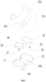
- a knee prosthesis in a first embodiment of the invention, includes: a tibial plateau 10, a femoral condyle component 20 and a spacer component 30.
- the femoral condyle component 20 is located above the tibial plateau 10.
- the femoral condyle component 20 includes a medial condyle articular surface 21 and a lateral condyle articular surface 22. There is a height difference H between the medial condyle articular surface 21 and the lateral condyle articular surface 22.
- the spacer component 30 is located between the tibial plateau 10 and the femoral condyle component 20.
- the tibial plateau 10 is arranged on a tibia after osteotomy.
- the femoral condyle component 20 is arranged on a femur after osteotomy.
- the spacer component 30 is arranged between the tibial plateau 10 and the femoral condyle component 20.
- the femoral condyle component 20 includes the medial condyle articular surface 21 and the lateral condyle articular surface 22.
- the medial condyle articular surface 21 and the lateral condyle articular surface 22 both contact with the spacer component 30.
- a height difference between a farthest point of the medial condyle articular surface 21 and a farthest point of the lateral condyle articular surface 22 is H, that is, the farthest point of the medial condyle articular surface 21 is slightly lower than the farthest point of the lateral condyle articular surface 22, and the farthest point of the medial condyle articular surface 21 is slightly lower than the farthest point of the lateral condyle articular surface 22.
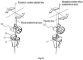
- the height difference H is set such that a joint line formed by connecting the farthest point of the medial condyle articular surface 21 and the farthest point of the lateral condyle articular surface 22 is not perpendicular to a tibia anatomical axis during use, but may be parallel to a horizontal plane.
- the arrangement mode may effectively avoid transverse shear stress generated by contact surfaces between the femoral condyle component 20 and the spacer component 30, and between the spacer component 30 and the tibial plateau 10 under the action of gravity. Therefore, the technical solution of the disclosure effectively solves the problem that a knee prosthesis is prone to wear caused by the shear stress in related technologies.
- rotary movement between a tibia and a femur during knee flexion and extension of the patient refers to rotation around an instantaneous center line perpendicular to the ground in an approximate horizontal plane, such that the patient has normal gait and movement feeling.
- the farthest point of the medial condyle articular surface and the farthest point of the lateral condyle articular surface of the femoral condyle component that is, the farthest point of the medial condyle articular surface is 0.5 mm-5 mm lower than the farthest point of the lateral condyle articular surface, so as to conform to an anatomical shape of a femoral condyle of a human body.
- the feature extends from a farthest point of a condyle articular surface to a posterior condyle.
- a specific height difference should be selected according to specific data of different patients.
- An inner surface of the femoral condyle component 20 making contact with an osteotomy surface on a femoral side is a femur and condyle integration surface.
- the femur and condyle integration surface is attached to the osteotomy surface on a femoral side during an operation.
- the knee prosthesis may be integrated with a physiological bone of the patient in a future rehabilitation process, so as to stabilize the prosthesis for a long term.
- the femoral condyle component 20, the spacer component 30 and the tibial plateau 10 are usually made of medical metals (such as cobalt alloy, titanium and titanium alloy, tantalum and tantalum alloy and magnesium alloy), medical ceramic materials (such as alumina ceramic, zirconia ceramic, silicon carbide ceramic and silicon nitride ceramic), and high polymer materials.
- medical metals such as cobalt alloy, titanium and titanium alloy, tantalum and tantalum alloy and magnesium alloy
- medical ceramic materials such as alumina ceramic, zirconia ceramic, silicon carbide ceramic and silicon nitride ceramic
- the knee may be regarded as a tibiofemoral joint composed of medial and lateral condyles of a distal end of a femur, medial and lateral plateaus as well as medial and lateral meniscuses of a proximal end of a tibia, from an anatomical structure.
- a lateral articular surface of the tibial plateau is bowl-shaped, and a convex lateral condyle articular surface of a femur and a concave lateral articular surface of the tibial plateau fit each other, such that a lateral joint pair of the knee is capable of flexing and extending flexibly on a sagittal plane.
- a recess on a medial articular surface of the tibial plateau is somewhat like a broad basin surrounded by meniscuses.
- the first 1/3 of the medial articular surface of the tibial plateau is a concave surface that rises gradually, while the second 2/3 is a concave surface that falls gradually.
- the medial articular surface of the tibial plateau cannot constantly and completely fit the medial femoral condyle during flexion and extension activities, but allows the medial femoral condyle to slide back and forth to a certain extent and roll with a plurality of instantaneous activity centers.
- the embodiment makes the following improvements to the prior art: As shown in Figs. 1-9 , in the first embodiment, the lateral condyle articular surface 22 is provided with a second spherical convex surface 221, and a lateral spacer 35 is provided with a second spherical concave surface 38 cooperating with the second spherical convex surface 221.
- the second spherical convex surface 221 contacts with the second spherical concave surface 38.
- the second spherical convex surface 221 is capable of sliding and rotating on the second spherical concave surface 38.
- the second spherical convex surface 221 fits the second spherical concave surface 38 well, such that sliding and rotation of the second spherical convex surface 221 may be more stable.
- the lateral condyle articular surface 22 is further provided with a first diameter-variable convex curved surface 222.
- the first diameter-variable convex curved surface 222 is connected to the second spherical convex surface 221, such that the lateral condyle articular surface 22 may slide in a larger space.
- the first diameter-variable convex curved surface 222 is capable of restraining lateral sides of a patella and a patellar ligament of the patient.
- Figs. 6 and 7 are cutaway views of A-A and B-B directions in Fig. 5 respectively.
- Fig. 6 mainly shows an outline of the medial condyle articular surface 21.
- Fig. 7 mainly shows an outline of the lateral condyle articular surface 22.
- Fig. 8 shows a borderline of the medial condyle articular surface 21.
- Fig. 9 shows a borderline of the lateral condyle articular surface 22.
- one part corresponds to the second spherical convex surface 221
- the other part corresponds to the first diameter-variable convex curved surface 222.
- a radius of an arc corresponding to the second spherical convex surface 221 is SR0.
- a borderline corresponding to the first diameter-variable convex curved surface 222 includes four arcs. Radii of four arcs are R1, R2, R3 and R4 sequentially. R1 indicates a position of an inward concave arc, and the other arcs corresponding to R2, R3 and R4 are outward convex arcs.
- a marked size relation of SR0-R4 may be adjusted according to an actual condition.
- a borderline corresponding to a second diameter-variable convex curved surface 211 also includes four arcs.
- Radii of four arcs are R5, R6, R7 and R8 sequentially.
- the arcs are all outward convex arcs.
- a marked size relation of R5-R9 may be adjusted according to an actual condition.
- the borderline corresponding to the first diameter-variable convex curved surface 222 may include two, three, five or more arcs, or curves in other forms, as long as smooth and stable fit between the first diameter-variable convex curved surface 222 and the lateral spacer 35 may be satisfied.
- the borderline corresponding to the second diameter-variable convex curved surface 211 may include two, three, five or more arcs, or curves in other forms, as long as smooth and stable fit between the second diameter-variable convex curved surface 211 and the medial spacer 34 may be satisfied.
- the medial condyle articular surface 21 is provided with the second diameter-variable convex curved surface 211
- the medial spacer 34 is provided with a first diameter-variable concave curved surface 37 cooperating with the second diameter-variable convex curved surface 211.
- the second diameter-variable convex curved surface 211 fits the first diameter-variable concave curved surface 37, so as to stabilize the knee.
- the second diameter-variable convex curved surface 211 makes local surface contact or even line contact with the first diameter-variable concave curved surface 37, so as to allow a certain sliding or rotational displacement between the femoral condyle component 20 and the spacer component 30.
- An anterior upper half of the medial condyle articular surface 21 is a convex diameter-variable curved surface and has a smooth transitive surface with an adjacent patellar slideway articular surface 23, so as to restrain medial sides of a patella and a ligament thereof.
- the medial condyle articular surface 21 of the femoral condyle component 20 is a convex continuous diameter-variable curved surface from an anterior lower half to a posterior condyle.
- the convex continuous diameter-variable curved surface makes contact with and matches the first diameter-variable concave curved surface 37, which is downward concave, of an upper surface of the medial spacer 34 of the spacer component 30.
- the second diameter-variable convex curved surface 211 fits the first diameter-variable concave curved surface 37, such that the medial condyle articular surface 21 may slide and rotate more stably, and a better use effect is provided for the patient.
- the spacer component 30 includes the medial spacer 34 cooperating with the medial condyle articular surface 21 and the lateral spacer 35 cooperating with the lateral condyle articular surface 22.
- An upper surface of the tibial plateau 10 is provided with a first spherical convex surface 11 at a position corresponding to the lateral spacer 35.
- the lateral spacer 35 is movably arranged on the tibial plateau 10.
- a lower surface of the lateral spacer 35 is provided with a first spherical concave surface 31 cooperating with the first spherical convex surface 11.
- the first spherical convex surface 11 is capable of fitting the first spherical concave surface 31.
- the first spherical concave surface 31 is capable of sliding and rotating on the first spherical convex surface 11.
- the lateral condyle articular surface 22 is capable of always keeping a large contact area with the lateral spacer 35, such that flexion stability is better, and moreover, service lives of the lateral condyle articular surface 22 and the spacer component 30 may be prolonged.
- the upper surface of the tibial plateau 10 is provided with a first flat surface 12 at a position corresponding to the medial condyle articular surface 21.
- a lower surface of the medial spacer 34 is provided with a second flat surface 32 cooperating with the first flat surface 12.
- the first flat surface 12 matches the second flat surface 32 in an attached manner.
- the second flat surface 32 is capable of moving or rotating relative to the first flat surface 12, thereby allowing movement of the medial condyle articular surface 21 relative to the spacer component 30. In this way, the femoral condyle component 20 has a movement effect closer to a physiological knee, which brings a better use experience to the patient.
- the spacer component 30 includes the medial spacer 34 cooperating with the medial condyle articular surface 21 and the lateral spacer 35 cooperating with the lateral condyle articular surface 22.
- the medial spacer 34 is separated from the lateral spacer 35.
- Both the medial spacer 34 and the lateral spacer 35 have their own movement modes. The separated arrangement may effectively avoid mutual restriction and interference between the medial spacer 34 and the lateral spacer 35, so as to make the knee prosthesis have a movement effect that better conforms to the physiological knee of the human body.
- the lateral spacer 35 moves to a rear edge of the tibial plateau 10.
- an upward concave spherical surface of the lower surface of the lateral spacer 35 still fits an upward convex spherical surface of the upper surface of a lateral side of the tibial plateau well, and the lateral spacer 35 has a backward inclination angle.
- the inclination angle prevents the rear edge of the femoral condyle component 20 from making contact with and biting the spacer component 30.
- the medial spacer 34 and the lateral spacer 35 may be connected together or integrated into a structure. In this case, it should be noted that considering a movement difference between the medial spacer 34 and the lateral spacer 35, the two need to be flexibly connected, so as to avoid mutual influences.
- the tibial plateau 10 and the spacer component 30 follow the femoral condyle component 20, to slide and rotate in all directions, and surfaces of the spacer component 30 and the femoral condyle component 20 fit each other, so as to avoid pressing or collision. Meanwhile, when the knee is highly flexed, a rear edge of a posterior condyle no longer makes edge contact with the spacer component, so as to avoid bite.
- the medial spacer may be integrated with the lateral spacer, and a structure of a spacer may be selected according to conditions of the patient.
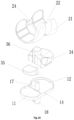
- the tibial plateau 10 includes a plateau body 14, a peripheral side wall 15 arranged on a circumferential edge of the plateau body 14, as well as a first medial wall 161 and a second medial wall 162 that are arranged inside the peripheral side wall 15.
- the medial spacer 34 is arranged inside a second space surrounded by the second medial wall 162 and the peripheral side wall 15.
- the lateral spacer 35 is arranged inside a first space surrounded by the first medial wall 161 and the peripheral side wall 15.
- the second medial wall 162 protrudes toward the medial spacer 34.
- the first medial wall 161 protrudes toward the lateral spacer 35.
- the peripheral side wall 15 cooperates with the first medial wall 161 and the second medial wall 162, so as to form the first space and the second space.
- the peripheral side wall 15, the first medial wall 161 and the second medial wall 162 have simple structures and are easy to form.
- the first medial wall 161 and the second medial wall 162 are in arc shapes that protrude outwards. Therefore, the first medial wall 161 and the second medial wall 162 may provide moving spaces for the lateral spacer 35 and the medial spacer 34 which rotate around an instantaneous center along with the femoral condyle component 20, so as to avoid collision between the medial walls and the spacers.
- the peripheral side wall 15 cooperates with the first medial wall 161 and the second medial wall 162, so as to prevent dislocation of the spacer component 30.
- the tibial plateau 10 includes the plateau body 14, the peripheral side wall 15 arranged on the circumferential edge of the plateau body 14, as well as the first medial wall 161 and the second medial wall 162 that are arranged inside the peripheral side wall 15.
- the medial spacer 34 is movably arranged inside the second space surrounded by the second medial wall 162 and the peripheral side wall 15.
- the lateral spacer 35 is movably arranged inside the first space surrounded by the first medial wall 161 and the peripheral side wall 15. The first space and the second space limit the lateral spacer 35 and the medial spacer 34 respectively, so as to prevent the medial spacer 34 and the lateral spacer 35 from moving excessively, resulting in damage of the knee prosthesis.
- the first space has a larger size than the lateral spacer 35, so as to make the lateral spacer 35 slide and/or rotate relative to the tibial plateau 10.
- the second space has a larger size than the medial spacer 34, so as to make the medial spacer 34 slide and/or rotate relative to the tibial plateau 10.
- the second space and the first space have larger sizes than the medial spacer 34 and the lateral spacer 35 respectively, such that the medial spacer 34 and the lateral spacer 35 are capable of moving in the second space and the first space respectively.
- the spacer component 30 has a larger moving space, thus effectively improving performance of the knee prosthesis.
- the tibial plateau 10 further includes an intramedullary rod 18 arranged below the plateau body 14, and there is an included angle ⁇ between a vertical line perpendicular to the upper surface of the tibial plateau 10 and the intramedullary rod 18.
- An average included angle between a femur anatomical axis and a gravity line is 9°.
- An average included angle between a tibia anatomical axis and the gravity line is 3°.
- the joint line of the knee (that is, a line connecting distal ends of medial and lateral condyles or a line connecting high points of medial and lateral plateaus of a tibia) is nearly a horizontal line.
- the reason for formation of the horizontal line is that a femur has a medial condyle longer than a lateral condyle in anatomy, such that an included angle (a lateral acute angle) between the line connecting the distal ends of the medial and lateral condyles and the femur anatomical axis in a coronal position is about 81°.
- an included angle (a medial acute angle) between the line connecting the high points of the medial and lateral plateaus of the tibia and the tibia anatomical axis is about 87°.
- a rotation surface is in the horizontal plane, and an instantaneous rotation center line is a plumb line. Therefore, the included angle ⁇ is set between 1° and 5°, preferably 3°.
- the included angle ⁇ is set to make the plateau body 14 parallel to the horizontal plane after the operation of the patient, thereby effectively avoiding shear stress between the spacer component 30 and the tibial plateau 10 and shear stress between the tibial plateau 10 and the tibia. Therefore, the knee prosthesis has a better use effect and effectively improves a use experience of the patient.
- the medial spacer 34 is fixedly arranged on the tibial plateau 10, and the spacer component 30 further includes a stand column 36 arranged on the medial spacer 34.
- the stand column 36 may replace a cruciate ligament so as to limit back-forth movement of the femoral condyle, and the stand column 36 has desirable structural strength.
- the femoral condyle component 20 further includes a patellar slideway articular surface 23 connected between the medial condyle articular surface 21 and the lateral condyle articular surface 22, as well as a limiting beam 24 between a posterior condyle of the medial condyle articular surface 21 and a posterior condyle of the lateral condyle articular surface 22.
- the stand column 36 is capable of limiting the limiting beam 24.
- the stand column 36 cooperates with the limiting beam 24.
- the stand column 36 is capable of moving in the limiting beam 24, so as to effectively prevent the knee prosthesis from moving forward excessively.
- the tibial plateau 10 is provided with a shaft 17, the stand column 36 is internally provided with an inner hole 361, and the shaft 17 is inserted into the inner hole 361.
- the medial spacer 34 is a fixed spacer, and a lower surface of the fixed spacer is flat.
- the inner hole 361 cooperates with the shaft 17 in a nested manner, so as to enhance mechanical strength of the stand column 36.
- the stand column 36 is capable of slightly rotating around the shaft 17, and then the spacer component 30 is capable of slightly rotating around the shaft 17, such that the knee prosthesis has more moving positions.
- the tibial plateau 10 may be prevented from biting the spacer component 30, and the limiting beam 24 may be limited.
- the upper surface of the tibial plateau 10 is provided with a third spherical convex surface 13 at a position corresponding to the medial condyle articular surface 21.
- a lower surface of the spacer component 30 is provided with a third spherical concave surface 33 cooperating with the third spherical convex surface 13.
- the third spherical convex surface 13 fits the third spherical convex surface 13.
- the embodiment provides four spherical friction pairs. Therefore, the design may make the knee prosthesis obtain greater joint mobility and make the whole process from the upright position to the flexed position reliable and stable. Furthermore, a sliding or moving effect of the femoral condyle component 20 is better, thus effectively improving performance of the knee prosthesis.
- the knee prosthesis includes: a tibial plateau 10, a femoral condyle component 20 and a spacer component 30.
- the femoral condyle component 20 is located above the tibial plateau 10.
- the femoral condyle component 20 includes a medial condyle articular surface 21 and a lateral condyle articular surface 22.
- the spacer component 30 is located between the tibial plateau 10 and the femoral condyle component 20.
- the spacer component 30 includes a medial spacer 34 cooperating with the medial condyle articular surface 21 and a lateral spacer 35 cooperating with the lateral condyle articular surface 22.
- An upper surface of the tibial plateau 10 is provided with a first spherical convex surface 11 at a position corresponding to the lateral spacer 35.
- the lateral spacer 35 is movably arranged on the tibial plateau 10.
- a lower surface of the lateral spacer 35 is provided with a first spherical concave surface 31 cooperating with the first spherical convex surface 11.
- the example has a difference from the above embodiments in that there is no height difference between the medial condyle articular surface and the lateral condyle articular surface.
- orientations or positional relations indicated by the terms “front, rear, upper, lower, left and right", “transverse, vertical, perpendicular, and horizontal”, “top and bottom”, etc. are based on the orientations or positional relations shown in the accompanying drawings and are only for facilitating the description of the present invention and simplifying the description, and in the absence of a statement to the contrary, the orientations do not indicate or imply that a device or element referred to must have a particular orientation or be constructed and operated in a particular orientation, and therefore will not be interpreted as limiting the scope of protection of the present invention; and the words “inside and outside” refer to inside and outside relative to an outline of each component itself.
- spatial relative terms such as “over”, “above”, “on an upper surface” and “on” may be used herein to describe spatial positional relations of one device or feature with other devices or features as shown in the drawings. It should be understood that the spatial relative terms are intended to include different orientations in use or operation in addition to the orientation of the device described in the drawings. For example, if the device in the drawings is inverted, the device described as “above” or “over” other devices or structures would then be positioned “below” or “under” the other devices or structures.
- the exemplary term “above” may include two orientations of “above” and “below.”
- the device may also be positioned (rotated 90° or at other orientations) in other different ways and the spatial relative description used herein is interpreted accordingly.
- words such as “first” and “second” are used to define parts only for convenience of distinguishing corresponding parts. Unless otherwise stated, the above words have no special meaning, so they cannot be understood as limiting the scope of protection of the present invention.
Landscapes
- Health & Medical Sciences (AREA)
- Orthopedic Medicine & Surgery (AREA)
- Physical Education & Sports Medicine (AREA)
- Cardiology (AREA)
- Oral & Maxillofacial Surgery (AREA)
- Transplantation (AREA)
- Engineering & Computer Science (AREA)
- Biomedical Technology (AREA)
- Heart & Thoracic Surgery (AREA)
- Vascular Medicine (AREA)
- Life Sciences & Earth Sciences (AREA)
- Animal Behavior & Ethology (AREA)
- General Health & Medical Sciences (AREA)
- Public Health (AREA)
- Veterinary Medicine (AREA)
- Prostheses (AREA)
Claims (13)
- Knieprothese, umfassend:ein Tibiaplateau (10);eine Femurkondylenkomponente (20), die über dem Tibiaplateau (10) bereitgestellt ist, wobei die Femurkondylenkomponente (20) eine mediale Kondylengelenkfläche (21) und eine laterale Kondylengelenkfläche (22) umfasst; undeine Abstandshalterkomponente (30) zwischen dem Tibiaplateau (10) und der Femurkondylenkomponente (20), wobei die Abstandshalterkomponente (30) einen medialen Abstandhalter (34), der mit der medialen Kondylengelenkfläche (21) zusammenwirkt, und einen lateralen Abstandhalter (35), der mit der lateralen Kondylengelenkfläche (22) zusammenwirkt, umfasst, wobei eine obere Fläche des Tibiaplateaus (10) mit einer ersten sphärischen konvexen Fläche (11) an einer Position versehen ist, die dem lateralen Abstandhalter (35) entspricht, der laterale Abstandhalter (35) beweglich auf dem Tibiaplateau (10) angeordnet ist und eine untere Fläche des lateralen Abstandhalters (35) mit einer ersten sphärischen konkaven Fläche (31) versehen ist, die mit der ersten sphärischen konvexen Fläche (11) zusammenwirkt;dadurch gekennzeichnet, dassdas Tibiaplateau (10) einen Plateaukörper (14), eine Umfangsseitenwand (15), die an einem umlaufenden Rand des Plateaukörpers (14) angeordnet ist, sowie eine erste mediale Wand (161) und eine zweite mediale Wand (162) umfasst, die innerhalb der Umfangsseitenwand (15) angeordnet sind, der laterale Abstandshalter (35) innerhalb eines ersten Raums angeordnet ist, der von der ersten medialen Wand (161) und der Umfangsseitenwand (15) umgeben ist, der mediale Abstandshalter (34) innerhalb eines zweiten Raums angeordnet ist, der von der zweiten medialen Wand (162) und der Umfangsseitenwand (15) umgeben ist, wobei eine Höhendifferenz (H) zwischen der medialen Kondylengelenkfläche (21) und der lateralen Kondylengelenkfläche (22) besteht.
- Knieprothese nach Anspruch 1, wobei die Höhendifferenz (H) zwischen 0,5 mm und 5 mm beträgt.
- Knieprothese nach Anspruch 1, wobei die laterale Kondylengelenkfläche (22) mit einer zweiten sphärischen konvexen Fläche (221) versehen ist und die Abstandshalterkomponente (30) mit einer zweiten sphärischen konkaven Fläche (38) versehen ist, die mit der zweiten sphärischen konvexen Fläche (221) zusammenwirkt.
- Knieprothese nach Anspruch 1, wobei die laterale Kondylengelenkfläche (22) ferner mit einer ersten durchmesserveränderlichen konvex gekrümmten Fläche (222) versehen ist.
- Knieprothese nach Anspruch 1, wobei die mediale Kondylengelenkfläche (21) mit einer zweiten durchmesserveränderlichen konvexen gekrümmten Fläche (211) versehen ist und die Abstandshalterkomponente (30) mit einer ersten durchmesserveränderlichen konkaven gekrümmten Fläche (37) versehen ist, die mit der zweiten durchmesserveränderlichen konvexen gekrümmten Fläche (211) zusammenwirkt.
- Knieprothese nach Anspruch 1, wobei die obere Fläche des Tibiaplateaus (10) mit einer ersten flachen Fläche (12) an einer Position versehen ist, die der medialen Kondylengelenkfläche (21) entspricht, und eine untere Fläche des medialen Abstandshalters (34) mit einer zweiten flachen Fläche (32) versehen ist, die mit der ersten flachen Fläche (12) zusammenwirkt; oder die obere Fläche des Tibiaplateaus (10) ist mit einer dritten sphärischen konvexen Fläche (13) an einer Position versehen, die der medialen Kondylengelenkfläche (21) entspricht, und eine untere Fläche des medialen Abstandshalters (34) ist mit einer dritten sphärischen konkaven Fläche (33) versehen, die mit der dritten sphärischen konvexen Fläche (13) zusammenwirkt.
- Knieprothese nach Anspruch 1, wobei die erste mediale Wand (161) in Richtung des lateralen Abstandshalters (35) vorsteht und die zweite mediale Wand (162) in Richtung des medialen Abstandshalters (34) vorsteht.
- Knieprothese nach Anspruch 1, wobei der laterale Abstandshalter (35) beweglich innerhalb des ersten Raums angeordnet ist und der mediale Abstandshalter (34) beweglich innerhalb des zweiten Raums angeordnet ist.
- Knieprothese nach Anspruch 8, wobei eine Größe des ersten Raums größer als eine Größe des lateralen Abstandshalters (35) ist, sodass der laterale Abstandshalter (35) relativ zum Tibiaplateau (10) gleiten und/oder sich drehen kann, und eine Größe des zweiten Raums größer als eine Größe des medialen Abstandshalters (34) ist, sodass der mediale Abstandshalter (34) relativ zum Tibiaplateau (10) gleiten und/oder sich drehen kann.
- Knieprothese nach Anspruch 1, wobei der mediale Abstandshalter (34) fest auf dem Tibiaplateau (10) angeordnet ist und die Abstandshalterkomponente (30) ferner eine auf dem medialen Abstandshalter (34) angeordnete Standsäule (36) umfasst.
- Knieprothese nach Anspruch 10, wobei die Femurkondylenkomponente (20) ferner eine Patellagleitbahn-Gelenkfläche (23), die zwischen der medialen Kondylengelenkfläche (21) und der lateralen Kondylengelenkfläche (22) verbunden ist, sowie einen Begrenzungsbalken (24) zwischen einer posterioren Kondyl der medialen Kondylengelenkfläche (21) und einer posterioren Kondyl der lateralen Kondylengelenkfläche (22) umfasst und die Standsäule (36) in der Lage ist, den Begrenzungsbalken (24) zu begrenzen.
- Knieprothese nach Anspruch 11, wobei das Tibiaplateau (10) mit einem Schaft (17) versehen ist, die Standsäule (36) innen mit einem Innenloch (361) versehen ist und der Schaft (17) in das Innenloch (361) eingesetzt ist.
- Knieprothese nach Anspruch 7, wobei das Tibiaplateau (10) ferner eine intramedulläre Stange (18) umfasst, die unterhalb des Plateaukörpers (14) angeordnet ist, und ein eingeschlossener Winkel α zwischen einer vertikalen Linie senkrecht zur oberen Fläche des Tibiaplateaus (10) und der intramedullären Stange (18) besteht.
Applications Claiming Priority (1)
| Application Number | Priority Date | Filing Date | Title |
|---|---|---|---|
| PCT/CN2020/077251 WO2021168822A1 (zh) | 2020-02-28 | 2020-02-28 | 膝关节假体 |
Publications (3)
| Publication Number | Publication Date |
|---|---|
| EP4112010A1 EP4112010A1 (de) | 2023-01-04 |
| EP4112010A4 EP4112010A4 (de) | 2023-04-12 |
| EP4112010B1 true EP4112010B1 (de) | 2025-05-21 |
Family
ID=77490621
Family Applications (1)
| Application Number | Title | Priority Date | Filing Date |
|---|---|---|---|
| EP20920892.5A Active EP4112010B1 (de) | 2020-02-28 | 2020-02-28 | Knieprothese |
Country Status (3)
| Country | Link |
|---|---|
| EP (1) | EP4112010B1 (de) |
| ES (1) | ES3033097T3 (de) |
| WO (1) | WO2021168822A1 (de) |
Families Citing this family (2)
| Publication number | Priority date | Publication date | Assignee | Title |
|---|---|---|---|---|
| CN113855341A (zh) * | 2021-11-01 | 2021-12-31 | 北京力达康科技有限公司 | 一种膝关节假体 |
| CN121129508A (zh) * | 2025-11-10 | 2025-12-16 | 嘉思特医疗器材(天津)股份有限公司 | 一种差异化式胫骨平台假体系统 |
Family Cites Families (13)
| Publication number | Priority date | Publication date | Assignee | Title |
|---|---|---|---|---|
| DE19529824A1 (de) * | 1995-08-14 | 1997-02-20 | Bodo Gnutzmann | Bikondyläre Knie-Endoprothese |
| GB9914074D0 (en) * | 1999-06-16 | 1999-08-18 | Btg Int Ltd | Tibial component |
| FR2805455B1 (fr) * | 2000-02-24 | 2002-04-19 | Aesculap Sa | Composant femoral d'une prothese du genou a trois rayons de courbure |
| JP3781186B2 (ja) * | 2002-02-13 | 2006-05-31 | 徹 勝呂 | 人工膝関節 |
| CN101123928A (zh) * | 2005-01-12 | 2008-02-13 | R·I·W·理查森 | 修复膝 |
| EP2255754B8 (de) * | 2007-11-02 | 2014-04-16 | Biomet UK Limited | Prothese zur Simulierung der natürlichen Kinematik |
| CN101214175B (zh) * | 2008-01-17 | 2011-03-23 | 四川大学 | 膝关节内用假体 |
| CN105030384B (zh) * | 2015-08-03 | 2018-04-10 | 北京威高亚华人工关节开发有限公司 | 一种全膝关节置换假体 |
| CN205849594U (zh) * | 2016-04-22 | 2017-01-04 | 北京市春立正达医疗器械股份有限公司 | 高匹配度生理型膝关节假体 |
| CN106109063B (zh) * | 2016-07-22 | 2019-02-01 | 西安市红会医院 | 一种人工膝关节假体 |
| CN108186167B (zh) * | 2018-01-23 | 2023-08-01 | 北京爱康宜诚医疗器材有限公司 | 膝关节假体 |
| CN109620480B (zh) * | 2019-01-31 | 2024-11-29 | 苏州微创关节医疗科技有限公司 | 单髁股骨假体 |
| CN111184598A (zh) * | 2020-02-28 | 2020-05-22 | 北京爱康宜诚医疗器材有限公司 | 膝关节假体 |
-
2020
- 2020-02-28 EP EP20920892.5A patent/EP4112010B1/de active Active
- 2020-02-28 WO PCT/CN2020/077251 patent/WO2021168822A1/zh not_active Ceased
- 2020-02-28 ES ES20920892T patent/ES3033097T3/es active Active
Also Published As
| Publication number | Publication date |
|---|---|
| EP4112010A4 (de) | 2023-04-12 |
| ES3033097T3 (en) | 2025-07-30 |
| EP4112010A1 (de) | 2023-01-04 |
| WO2021168822A1 (zh) | 2021-09-02 |
Similar Documents
| Publication | Publication Date | Title |
|---|---|---|
| US20250032264A1 (en) | Total knee implant prosthesis assembly and method | |
| EP2165681B1 (de) | sowohl kongruent als auch inkongruent gelenkig gelagerte Endoprothese mit stationärem Lager | |
| CN106137469B (zh) | 用于恢复正常弯曲范围和膝关节运动性能的植入物 | |
| EP1696835B1 (de) | Tibiaknieprothese | |
| EP1684672B1 (de) | Gelenkeinsatz mit hoher biegung | |
| US9220601B2 (en) | Orthopaedic femoral component having controlled condylar curvature | |
| US8795380B2 (en) | Orthopaedic knee prosthesis having controlled condylar curvature | |
| CN111184598A (zh) | 膝关节假体 | |
| KR101704954B1 (ko) | 대퇴슬 임플란트 시스템용 대퇴골 부품 | |
| JP2004167255A (ja) | 人工膝関節用大腿骨コンポーネント | |
| JPH05200057A (ja) | 人工関節、とくに人工ひざ関節 | |
| EP4112010B1 (de) | Knieprothese | |
| CN212089847U (zh) | 膝关节假体 | |
| CN113040979A (zh) | 膝关节假体 |
Legal Events
| Date | Code | Title | Description |
|---|---|---|---|
| STAA | Information on the status of an ep patent application or granted ep patent |
Free format text: STATUS: THE INTERNATIONAL PUBLICATION HAS BEEN MADE |
|
| PUAI | Public reference made under article 153(3) epc to a published international application that has entered the european phase |
Free format text: ORIGINAL CODE: 0009012 |
|
| STAA | Information on the status of an ep patent application or granted ep patent |
Free format text: STATUS: REQUEST FOR EXAMINATION WAS MADE |
|
| 17P | Request for examination filed |
Effective date: 20220927 |
|
| AK | Designated contracting states |
Kind code of ref document: A1 Designated state(s): AL AT BE BG CH CY CZ DE DK EE ES FI FR GB GR HR HU IE IS IT LI LT LU LV MC MK MT NL NO PL PT RO RS SE SI SK SM TR |
|
| A4 | Supplementary search report drawn up and despatched |
Effective date: 20230315 |
|
| RIC1 | Information provided on ipc code assigned before grant |
Ipc: A61F 2/38 20060101AFI20230309BHEP |
|
| DAV | Request for validation of the european patent (deleted) | ||
| DAX | Request for extension of the european patent (deleted) | ||
| GRAP | Despatch of communication of intention to grant a patent |
Free format text: ORIGINAL CODE: EPIDOSNIGR1 |
|
| STAA | Information on the status of an ep patent application or granted ep patent |
Free format text: STATUS: GRANT OF PATENT IS INTENDED |
|
| INTG | Intention to grant announced |
Effective date: 20250204 |
|
| GRAS | Grant fee paid |
Free format text: ORIGINAL CODE: EPIDOSNIGR3 |
|
| GRAA | (expected) grant |
Free format text: ORIGINAL CODE: 0009210 |
|
| STAA | Information on the status of an ep patent application or granted ep patent |
Free format text: STATUS: THE PATENT HAS BEEN GRANTED |
|
| AK | Designated contracting states |
Kind code of ref document: B1 Designated state(s): AL AT BE BG CH CY CZ DE DK EE ES FI FR GB GR HR HU IE IS IT LI LT LU LV MC MK MT NL NO PL PT RO RS SE SI SK SM TR |
|
| REG | Reference to a national code |
Ref country code: GB Ref legal event code: FG4D |
|
| REG | Reference to a national code |
Ref country code: CH Ref legal event code: EP |
|
| REG | Reference to a national code |
Ref country code: DE Ref legal event code: R096 Ref document number: 602020051882 Country of ref document: DE |
|
| REG | Reference to a national code |
Ref country code: IE Ref legal event code: FG4D |
|
| REG | Reference to a national code |
Ref country code: ES Ref legal event code: FG2A Ref document number: 3033097 Country of ref document: ES Kind code of ref document: T3 Effective date: 20250730 |
|
| REG | Reference to a national code |
Ref country code: NL Ref legal event code: MP Effective date: 20250521 |
|
| PG25 | Lapsed in a contracting state [announced via postgrant information from national office to epo] |
Ref country code: FI Free format text: LAPSE BECAUSE OF FAILURE TO SUBMIT A TRANSLATION OF THE DESCRIPTION OR TO PAY THE FEE WITHIN THE PRESCRIBED TIME-LIMIT Effective date: 20250521 Ref country code: PT Free format text: LAPSE BECAUSE OF FAILURE TO SUBMIT A TRANSLATION OF THE DESCRIPTION OR TO PAY THE FEE WITHIN THE PRESCRIBED TIME-LIMIT Effective date: 20250922 |
|
| REG | Reference to a national code |
Ref country code: LT Ref legal event code: MG9D |
|
| PG25 | Lapsed in a contracting state [announced via postgrant information from national office to epo] |
Ref country code: GR Free format text: LAPSE BECAUSE OF FAILURE TO SUBMIT A TRANSLATION OF THE DESCRIPTION OR TO PAY THE FEE WITHIN THE PRESCRIBED TIME-LIMIT Effective date: 20250822 Ref country code: NO Free format text: LAPSE BECAUSE OF FAILURE TO SUBMIT A TRANSLATION OF THE DESCRIPTION OR TO PAY THE FEE WITHIN THE PRESCRIBED TIME-LIMIT Effective date: 20250821 |
|
| PG25 | Lapsed in a contracting state [announced via postgrant information from national office to epo] |
Ref country code: PL Free format text: LAPSE BECAUSE OF FAILURE TO SUBMIT A TRANSLATION OF THE DESCRIPTION OR TO PAY THE FEE WITHIN THE PRESCRIBED TIME-LIMIT Effective date: 20250521 Ref country code: NL Free format text: LAPSE BECAUSE OF FAILURE TO SUBMIT A TRANSLATION OF THE DESCRIPTION OR TO PAY THE FEE WITHIN THE PRESCRIBED TIME-LIMIT Effective date: 20250521 |
|
| PG25 | Lapsed in a contracting state [announced via postgrant information from national office to epo] |
Ref country code: BG Free format text: LAPSE BECAUSE OF FAILURE TO SUBMIT A TRANSLATION OF THE DESCRIPTION OR TO PAY THE FEE WITHIN THE PRESCRIBED TIME-LIMIT Effective date: 20250521 |
|
| PG25 | Lapsed in a contracting state [announced via postgrant information from national office to epo] |
Ref country code: HR Free format text: LAPSE BECAUSE OF FAILURE TO SUBMIT A TRANSLATION OF THE DESCRIPTION OR TO PAY THE FEE WITHIN THE PRESCRIBED TIME-LIMIT Effective date: 20250521 |
|
| PG25 | Lapsed in a contracting state [announced via postgrant information from national office to epo] |
Ref country code: RS Free format text: LAPSE BECAUSE OF FAILURE TO SUBMIT A TRANSLATION OF THE DESCRIPTION OR TO PAY THE FEE WITHIN THE PRESCRIBED TIME-LIMIT Effective date: 20250821 |
|
| PG25 | Lapsed in a contracting state [announced via postgrant information from national office to epo] |
Ref country code: IS Free format text: LAPSE BECAUSE OF FAILURE TO SUBMIT A TRANSLATION OF THE DESCRIPTION OR TO PAY THE FEE WITHIN THE PRESCRIBED TIME-LIMIT Effective date: 20250921 |
|
| PG25 | Lapsed in a contracting state [announced via postgrant information from national office to epo] |
Ref country code: LV Free format text: LAPSE BECAUSE OF FAILURE TO SUBMIT A TRANSLATION OF THE DESCRIPTION OR TO PAY THE FEE WITHIN THE PRESCRIBED TIME-LIMIT Effective date: 20250521 |
|
| REG | Reference to a national code |
Ref country code: AT Ref legal event code: MK05 Ref document number: 1796157 Country of ref document: AT Kind code of ref document: T Effective date: 20250521 |
|
| PG25 | Lapsed in a contracting state [announced via postgrant information from national office to epo] |
Ref country code: AT Free format text: LAPSE BECAUSE OF FAILURE TO SUBMIT A TRANSLATION OF THE DESCRIPTION OR TO PAY THE FEE WITHIN THE PRESCRIBED TIME-LIMIT Effective date: 20250521 Ref country code: DK Free format text: LAPSE BECAUSE OF FAILURE TO SUBMIT A TRANSLATION OF THE DESCRIPTION OR TO PAY THE FEE WITHIN THE PRESCRIBED TIME-LIMIT Effective date: 20250521 Ref country code: SM Free format text: LAPSE BECAUSE OF FAILURE TO SUBMIT A TRANSLATION OF THE DESCRIPTION OR TO PAY THE FEE WITHIN THE PRESCRIBED TIME-LIMIT Effective date: 20250521 |
|
| PG25 | Lapsed in a contracting state [announced via postgrant information from national office to epo] |
Ref country code: CZ Free format text: LAPSE BECAUSE OF FAILURE TO SUBMIT A TRANSLATION OF THE DESCRIPTION OR TO PAY THE FEE WITHIN THE PRESCRIBED TIME-LIMIT Effective date: 20250521 |
|
| PG25 | Lapsed in a contracting state [announced via postgrant information from national office to epo] |
Ref country code: EE Free format text: LAPSE BECAUSE OF FAILURE TO SUBMIT A TRANSLATION OF THE DESCRIPTION OR TO PAY THE FEE WITHIN THE PRESCRIBED TIME-LIMIT Effective date: 20250521 |
|
| PG25 | Lapsed in a contracting state [announced via postgrant information from national office to epo] |
Ref country code: SK Free format text: LAPSE BECAUSE OF FAILURE TO SUBMIT A TRANSLATION OF THE DESCRIPTION OR TO PAY THE FEE WITHIN THE PRESCRIBED TIME-LIMIT Effective date: 20250521 |
|
| PG25 | Lapsed in a contracting state [announced via postgrant information from national office to epo] |
Ref country code: IT Free format text: LAPSE BECAUSE OF FAILURE TO SUBMIT A TRANSLATION OF THE DESCRIPTION OR TO PAY THE FEE WITHIN THE PRESCRIBED TIME-LIMIT Effective date: 20250521 |
|
| REG | Reference to a national code |
Ref country code: DE Ref legal event code: R097 Ref document number: 602020051882 Country of ref document: DE |
|
| PLBE | No opposition filed within time limit |
Free format text: ORIGINAL CODE: 0009261 |
|
| STAA | Information on the status of an ep patent application or granted ep patent |
Free format text: STATUS: NO OPPOSITION FILED WITHIN TIME LIMIT |
|
| REG | Reference to a national code |
Ref country code: CH Ref legal event code: L10 Free format text: ST27 STATUS EVENT CODE: U-0-0-L10-L00 (AS PROVIDED BY THE NATIONAL OFFICE) Effective date: 20260402 |
|
| 26N | No opposition filed |
Effective date: 20260224 |