EP4112032B1 - Operationstischsystem, operationstisch und fernbedienung - Google Patents
Operationstischsystem, operationstisch und fernbedienung Download PDFInfo
- Publication number
- EP4112032B1 EP4112032B1 EP21181964.4A EP21181964A EP4112032B1 EP 4112032 B1 EP4112032 B1 EP 4112032B1 EP 21181964 A EP21181964 A EP 21181964A EP 4112032 B1 EP4112032 B1 EP 4112032B1
- Authority
- EP
- European Patent Office
- Prior art keywords
- light emitting
- interface
- table top
- interface joint
- light
- Prior art date
- Legal status (The legal status is an assumption and is not a legal conclusion. Google has not performed a legal analysis and makes no representation as to the accuracy of the status listed.)
- Active
Links
Images

Classifications
-
- A—HUMAN NECESSITIES
- A61—MEDICAL OR VETERINARY SCIENCE; HYGIENE
- A61G—TRANSPORT, PERSONAL CONVEYANCES OR ACCOMMODATION SPECIALLY ADAPTED FOR PATIENTS OR DISABLED PERSONS; OPERATING TABLES OR CHAIRS; CHAIRS FOR DENTISTRY; FUNERAL DEVICES
- A61G13/00—Operating tables; Auxiliary appliances therefor
-
- A—HUMAN NECESSITIES
- A61—MEDICAL OR VETERINARY SCIENCE; HYGIENE
- A61G—TRANSPORT, PERSONAL CONVEYANCES OR ACCOMMODATION SPECIALLY ADAPTED FOR PATIENTS OR DISABLED PERSONS; OPERATING TABLES OR CHAIRS; CHAIRS FOR DENTISTRY; FUNERAL DEVICES
- A61G13/00—Operating tables; Auxiliary appliances therefor
- A61G13/02—Adjustable operating tables; Controls therefor
- A61G13/06—Adjustable operating tables; Controls therefor raising or lowering of the whole table surface
-
- A—HUMAN NECESSITIES
- A61—MEDICAL OR VETERINARY SCIENCE; HYGIENE
- A61G—TRANSPORT, PERSONAL CONVEYANCES OR ACCOMMODATION SPECIALLY ADAPTED FOR PATIENTS OR DISABLED PERSONS; OPERATING TABLES OR CHAIRS; CHAIRS FOR DENTISTRY; FUNERAL DEVICES
- A61G13/00—Operating tables; Auxiliary appliances therefor
- A61G13/10—Parts, details or accessories
-
- A—HUMAN NECESSITIES
- A61—MEDICAL OR VETERINARY SCIENCE; HYGIENE
- A61G—TRANSPORT, PERSONAL CONVEYANCES OR ACCOMMODATION SPECIALLY ADAPTED FOR PATIENTS OR DISABLED PERSONS; OPERATING TABLES OR CHAIRS; CHAIRS FOR DENTISTRY; FUNERAL DEVICES
- A61G13/00—Operating tables; Auxiliary appliances therefor
- A61G13/10—Parts, details or accessories
- A61G13/12—Rests specially adapted therefor; Arrangements of patient-supporting surfaces
- A61G13/1205—Rests specially adapted therefor; Arrangements of patient-supporting surfaces for specific parts of the body
- A61G13/121—Head or neck
-
- A—HUMAN NECESSITIES
- A61—MEDICAL OR VETERINARY SCIENCE; HYGIENE
- A61G—TRANSPORT, PERSONAL CONVEYANCES OR ACCOMMODATION SPECIALLY ADAPTED FOR PATIENTS OR DISABLED PERSONS; OPERATING TABLES OR CHAIRS; CHAIRS FOR DENTISTRY; FUNERAL DEVICES
- A61G13/00—Operating tables; Auxiliary appliances therefor
- A61G13/10—Parts, details or accessories
- A61G13/12—Rests specially adapted therefor; Arrangements of patient-supporting surfaces
- A61G13/1205—Rests specially adapted therefor; Arrangements of patient-supporting surfaces for specific parts of the body
- A61G13/1245—Knees, upper or lower legs
-
- A—HUMAN NECESSITIES
- A61—MEDICAL OR VETERINARY SCIENCE; HYGIENE
- A61G—TRANSPORT, PERSONAL CONVEYANCES OR ACCOMMODATION SPECIALLY ADAPTED FOR PATIENTS OR DISABLED PERSONS; OPERATING TABLES OR CHAIRS; CHAIRS FOR DENTISTRY; FUNERAL DEVICES
- A61G13/00—Operating tables; Auxiliary appliances therefor
- A61G13/02—Adjustable operating tables; Controls therefor
- A61G13/08—Adjustable operating tables; Controls therefor the table being divided into different adjustable sections
-
- A—HUMAN NECESSITIES
- A61—MEDICAL OR VETERINARY SCIENCE; HYGIENE
- A61G—TRANSPORT, PERSONAL CONVEYANCES OR ACCOMMODATION SPECIALLY ADAPTED FOR PATIENTS OR DISABLED PERSONS; OPERATING TABLES OR CHAIRS; CHAIRS FOR DENTISTRY; FUNERAL DEVICES
- A61G2203/00—General characteristics of devices
- A61G2203/10—General characteristics of devices characterised by specific control means, e.g. for adjustment or steering
- A61G2203/12—Remote controls
-
- A—HUMAN NECESSITIES
- A61—MEDICAL OR VETERINARY SCIENCE; HYGIENE
- A61G—TRANSPORT, PERSONAL CONVEYANCES OR ACCOMMODATION SPECIALLY ADAPTED FOR PATIENTS OR DISABLED PERSONS; OPERATING TABLES OR CHAIRS; CHAIRS FOR DENTISTRY; FUNERAL DEVICES
- A61G2203/00—General characteristics of devices
- A61G2203/10—General characteristics of devices characterised by specific control means, e.g. for adjustment or steering
- A61G2203/16—Touchpads
-
- A—HUMAN NECESSITIES
- A61—MEDICAL OR VETERINARY SCIENCE; HYGIENE
- A61G—TRANSPORT, PERSONAL CONVEYANCES OR ACCOMMODATION SPECIALLY ADAPTED FOR PATIENTS OR DISABLED PERSONS; OPERATING TABLES OR CHAIRS; CHAIRS FOR DENTISTRY; FUNERAL DEVICES
- A61G2203/00—General characteristics of devices
- A61G2203/10—General characteristics of devices characterised by specific control means, e.g. for adjustment or steering
- A61G2203/20—Displays or monitors
-
- A—HUMAN NECESSITIES
- A61—MEDICAL OR VETERINARY SCIENCE; HYGIENE
- A61G—TRANSPORT, PERSONAL CONVEYANCES OR ACCOMMODATION SPECIALLY ADAPTED FOR PATIENTS OR DISABLED PERSONS; OPERATING TABLES OR CHAIRS; CHAIRS FOR DENTISTRY; FUNERAL DEVICES
- A61G2203/00—General characteristics of devices
- A61G2203/30—General characteristics of devices characterised by sensor means
Definitions
- Remote controls for controlling the movement of the operating table often have physical buttons rather than a touch screen so that the operating person can locate the physical buttons on the remote control by touch and also perceive the mechanical feedback generated by the movement of such a button when actuated.
- WO 2016/131659 describes such a remote control that combines physical buttons with a display that depicts a stylised image of the operating table being controlled. To facilitate the control of the table for the operating person, the stylised image of the operating table is shown with controllable elements highlighted in different colours, with these colours reproduced on the physical buttons configured to control the controllable elements. While such a display provides a recognisable image of the operating table, the operator must first identify which element is to be controlled on the screen with the attendant danger that attention is drawn away from the table and the patient.
- a system comprising an operating table for supporting a patient, the operating table having a base and a table top, the table top comprising: at least three elements, preferably including at least two movable elements, and at least two interface joints, each interface joint serving as a movable connection between two adjacent elements, the operating table further comprising a controller arranged to control each interface joint to actuate a movement of at least one adjacent element relative to the other; a light emitting arrangement being associated with each interface joint and adapted to display light in a pattern that is visible on at least one end of each interface joint at a lateral edge of the table top, a characteristic of the pattern displayed by the light emitting arrangement being visibly unique to the associated interface joint such that the interface joints are visually distinguishable from one another.
- the unique characteristic of the pattern displayed by the light emitting arrangement comprises a first colour associated with a first interface joint and a second colour associated with a second interface joint; wherein the remote control comprises a display which displays a representation of at least part of the operating table during operation; wherein said display shows a first table element which is movable by the first interface joint at least partly in the first colour, and shows a second table element which is movable by the second interface joint at least partly in the second colour.
- At least some of the interface joints are rotational joints, which upon actuation cause the pivotal movement of one adjacent element relative to the other.
- the light emitting arrangement comprises a plurality of LEDs arranged in said interface joint.
- the light emitting arrangement may further comprise a circuit board having a series of LEDs that are arranged substantially in a ring and are individually controllable in terms of colour and intensity of emitted light, the interface joint preferably further comprising a sealable cover plate with light transparent apertures corresponding to the position of the LEDs.
- the operating table further comprises sensors configured to detecting a collision and being in communication with the controller, the controller being adapted to control the light emitting arrangements associated with an interface joint located closest to a detected collision to display a light pattern indicative of a collision.
- the present disclosure relates to an operating table for supporting a patient, the operating table having a base and a table top, the table top comprising: at least three elements that are movable relative to one another and at least two interface joints, each interface joint serving as a movable connection between two adjacent elements, the operating table further comprising a controller arranged to control each interface joint to actuate a movement of at least one adjacent element relative to the other; a light emitting arrangement being associated with each interface joint and adapted to display light in a pattern that is visible on at least one end of each interface joint at a lateral edge of the table top, a characteristic of the pattern displayed by the light emitting arrangement being visibly unique to the associated interface joint such that the interface joints are visually distinguishable from one another.
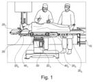
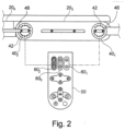
- the interface joints 40 1 and 40 2 depicted in Fig. 2 have an axis of rotation that extends from one side of the operating table to the other.
- a light emitting arrangement 42 is disposed in the interface joint 40 on the opposite side of the operating table 10 also, i.e. on the side not shown in Fig. 2 , and is configured to display the same light pattern.
- Some interface joints 40 will not be visible on both sides, for example joints that allow movement of leg supports that move individually. In these cases, only one light emitting arrangement is associated with the joint.
- light emitting arrangements are positioned at one or both ends of an axis of rotation of interface joints.
- a remote control 50 that can be used by a member of the operating staff to remotely configure the arrangement of the operating table, and in some cases also receive configuration or status information from the operating table 10.
- the remote control 50 is provided with a number of touch controls in the form of physical buttons 60 for controlling specific movements of the table.
- Each touch control 60 1 , 60 2 and 60 3 are dedicated to the control of various interface joints 40 between elements of the table top 20 as is illustrated by the dashed line between touch control 60 1 and interface joint 40 1 and the dash-dotted line between touch control 60 2 and interface joint 60 2 .
- each touch control 60 is provided with a visible pattern or design that mirrors at least one characteristic of the light pattern emitted by the light emitting arrangement of the associated joint 40.
- the additional table top elements 20 1-2 , 4-5 could include one or more additional interface joints thereon, with each interface joint also having at least one respective light emitting arrangement 42.
- the additional table top elements 20 1-2 , 4-5 could be modular for attachment and removal from the central table top element 20 3 to create different table configurations.
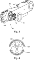
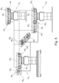
- the light emitting arrangement 42 is illustrated in more detail in Fig. 4 and comprises an arrangement of RGB LEDs 420 arranged in a circular pattern on its outer edge. Positioning cut-outs are also provided on the PCB to ensure the correct orientation of the arrangement 42 when installed.
- the light intensity and colour i.e. the relative proportions of red, green and blue components, of the LEDs 420 can be varied, preferably individually. This can be achieved by connecting the LEDs as a shift register.
- Contacts 430 are provided for connecting the PCB to a power supply and control signals as will be described further with reference to Fig. 6 .
- the light emitting elements 42 in each interface joint 40 1 - 40 3 are further preferably configured to display a characteristic pattern according to function.
- those interface joints that are used for adjusting a patient's back will display the same colour or pattern.
- the colour or pattern displayed by a light emitting arrangement 42 may change during configuration of the operating table in order to reflect a patient's orientation, for example, reversing head and foot ends. In this way, the same touch control 60 1 - 60 3 will be used for adjusting a patient's back regardless of table configuration.
- tables 10 and table tops 20 may have at least two interface joints 40, each interface joint having at least one respective light emitting element 42 aligned with a rotational axis of the joint 40 at an edge of the table top 10.
- Remote controls 50 for use with such tables and tale tops may include at least two touch controls 60, and more specifically at least as many touch controls 60 as the table/table top has interface joints 40, each touch control 60 having a different respective colour and/or pattern associated therewith.
- each light emitting element 42 can have a colour and/or a pattern corresponding to a single touch control 60 on the remote control 50 which is controlling the corresponding interface joint 40 at that time.
- each light emitting element 42 is capable of showing at least two or at least three different colours.
- a remote control 50 communicates wirelessly or by wired connection with the controller 100 to send control signals for operating the interface joints.
- a remote control 50 may also be equipped with a display for displaying a stylised pictogram of the operating table configuration, with different table elements shown in different colours or patterns, such as those described in WO 2016/131659 A1 .
- the controller 100 may also transmit information to the remote control on the status or configuration of an operating table 10.
- the controller 100 may also be in communication with various sensors 70, represented in Fig. 6 by a single block.
- the possible feedback messages given in Table 1 are just some possible examples and that the light emitting arrangements 42 may be controlled to provide an immediate visible indication of a prevailing condition to the operating staff without adding to the audible overload already present in an operating theatre, while also drawing attention to the area of the table concerned.
- the light emitting arrangements 42 may be controlled to emit a flashing pattern or increase in intensity in response to the actuation of the corresponding touch control 60 of the remote control 50. In this way, the user can be provided with immediate visible feedback of which interface joint 40 is controlled by which touch control 60.
- Trendelenburg tilting or lateral sliding of the table top 20 could be indicated by movement of lights on a corresponding light emitting element 42 near the top of the column, for example by showing a clockwise or counter-clockwise rotation direction which corresponds to the tilting/pivoting or sliding direction of the table top 20.
- a light emitting element 42 such as in Figure 2 , but positioned near the top of the column or another useful location.
- the same or a different light emitting element 42, color corresponding to a controlling touch control 60 could also be used to show upward or downward movement of the table top 20 by the column by movement of individual lights in an upward or downward movement patters.
Landscapes
- Health & Medical Sciences (AREA)
- Engineering & Computer Science (AREA)
- Biomedical Technology (AREA)
- Life Sciences & Earth Sciences (AREA)
- Animal Behavior & Ethology (AREA)
- General Health & Medical Sciences (AREA)
- Public Health (AREA)
- Veterinary Medicine (AREA)
- Neurosurgery (AREA)
- Otolaryngology (AREA)
- Accommodation For Nursing Or Treatment Tables (AREA)
Claims (13)
- System, umfassend einen Operationstisch (10) zum Lagern eines Patienten, wobei der Operationstisch eine Basis (30) und eine Tischplatte (20) aufweist, wobei die Tischplatte (20) Folgendes umfasst:- mindestens drei Elemente (201-206) und- mindestens zwei Schnittstellengelenke (401-403), wobei jedes Schnittstellengelenk als eine bewegbare Verbindung zwischen zwei benachbarten Elementen dient,wobei der Operationstisch ferner Folgendes umfasst:- eine Steuerung (100), die dazu angeordnet ist, jedes Schnittstellengelenk (401-403) zu steuern, um eine Bewegung von mindestens einem benachbarten Elements relativ zu dem anderen auszulösen;- eine Licht emittierende Anordnung (42), die jedem der Schnittstellengelenke (401-403)zugeordnet ist und dazu angepasst ist, Licht in einem Muster anzuzeigen, das an mindestens einem Ende jedes Schnittstellengelenks an einer seitlichen Kante der Tischplatte (20) sichtbar ist, wobei eine Eigenschaft des Musters, das von der Licht emittierenden Anordnung (42) angezeigt wird, für das zugeordnete Schnittstellengelenk derart sichtbar eindeutig ist, dass die Schnittstellengelenke (401-403) optisch voneinander unterscheidbar sind.
- System nach Anspruch 1, ferner umfassend eine Fernsteuerung (50), wobei die Fernsteuerung (50) dazu angepasst ist, mit der Steuerung (100) zu kommunizieren, und umfassend Taststeuerungen (601-603) zum Kommunizieren von Signalen zum Steuern einer Bewegung der Schnittstellengelenke (401-403), wobei jede Taststeuerung einem Schnittstellengelenk zugeordnet ist und mit einem sichtbaren Muster bereitgestellt ist, das eine Eigenschaft aufweist, die im Wesentlichen die gleiche ist wie diejenige, die durch die Licht emittierende Anordnung (42) des zugeordneten Schnittstellengelenks (401-403) angezeigt wird.
- System nach Anspruch 1 oder 2, wobei die eindeutige Eigenschaft des Musters, das von der Licht emittierenden Anordnung (42) angezeigt wird, eine Farbe umfasst, wobei die Licht emittierende Anordnung (42) bevorzugt dazu angepasst ist, ein Lichtmuster anzuzeigen, das auf die Richtung und/oder den Grad einer Bewegung des Schnittstellengelenks (401-403) hinweist, und wobei die Licht emittierende Anordnung (42) bevorzugt dazu angepasst ist, ein Lichtmuster anzuzeigen, das auf einen Verbindungsstatus des Schnittstellengelenks (401-403) hinweist.
- System nach Anspruch 2 oder 3, wobei die eindeutige Eigenschaft des Musters, das von der Licht emittierenden Anordnung (42) angezeigt wird, eine erste Farbe, die einem ersten Schnittstellengelenk (401) zugeordnet ist, und eine zweite Farbe, die einem zweiten Schnittstellengelenk (402) zugeordnet ist, umfasst;
wobei die Fernsteuerung (50) eine Anzeige umfasst, die während einer Operation eine Darstellung von mindestens einem Teil des Operationstischs anzeigt; wobei die Anzeige ein erstes Tischelement, das durch das erste Schnittstellengelenk bewegbar ist, mindestens teilweise in der ersten Farbe zeigt und ein zweites Tischelement, das durch das zweite Schnittstellengelenk bewegbar ist, mindestens teilweise in der zweiten Farbe zeigt. - System nach einem der Ansprüche 2 bis 4, wobei die Steuerung (100) dazu konfiguriert ist, das Lichtmuster, das von der Licht emittierenden Anordnung (42) angezeigt wird, automatisch zu ändern, um dem Lichtmuster, das auf einer zugeordneten Taststeuerung (601-603) bereitgestellt ist, zu entsprechen.
- System nach einem der vorhergehenden Ansprüche, wobei zwei Licht emittierende Anordnungen (42) dem gleichen Schnittstellengelenk (401-403) zugeordnet sind, wobei die zwei Licht emittierenden Anordnungen (42) dazu angepasst sind, die gleiche Mustereigenschaft auf gegenüberliegenden seitlichen Seiten der Tischplatte anzuzeigen.
- System nach einem der vorhergehenden Ansprüche, wobei die Licht emittierende Anordnung (42) eine Vielzahl von LEDs (420), die in dem Schnittstellengelenk angeordnet ist, umfasst, wobei das Schnittstellegelenk (401-403) eine abdichtbare Abdeckplatte (44) mit lichtdurchlässigen Öffnungen, die den Positionen der LEDs entsprechen, umfasst.
- System nach Anspruch 7, wobei die Schnittstellengelenke (401-403) Drehgelenke sind, die bei Auslösung die Schwenkbewegung von einem benachbarten Element relativ zu dem anderen veranlassen, wobei die LEDs in einer im Wesentlichen kreisförmigen Anordnung angeordnet sind und die Mitte der kreisförmigen Anordnung weitestgehend einer Drehachse des Schnittstellengelenks entspricht.
- System nach Anspruch 8, wobei die Vielzahl von LEDs in Bezug auf Farbe und Intensität des emittierten Lichts individuell steuerbar ist.
- System nach einem der vorhergehenden Ansprüche, wobei der Operationstisch (10) ferner Sensoren (70) umfasst, die dazu konfiguriert sind, eine Kollision zu detektieren und in Kommunikation mit der Steuerung zu stehen, wobei die Steuerung dazu angepasst ist, die Licht emittierenden Anordnungen, die einem Schnittstellengelenk, das sich am dichtesten an einer detektierten Kollision befindet, zu steuern, ein Lichtmuster anzuzeigen, das auf eine Kollision hinweist.
- System nach einem der vorhergehenden Ansprüche, wobei der Operationstisch (10) ein Kopfende zum Lagern eines Kopfs und eines Oberkörpers eines Patienten und ein Beinende zum Lagern der Beine eines Patienten umfasst; wobei ein Kopfendenschnittstellengelenk (401) zur Bewegung des Kopfendes des Operationstischs einer Licht emittierenden Anordnung (42) für das Kopfende zugeordnet ist, die dazu konfiguriert ist, eine erste Farbe, die dem Kopfende zugeordnet ist, zu emittieren; wobei mindestens ein Beinendenschnittstellengelenk (402) zur Bewegung des Beinendes des Operationstischs einer Licht emittierenden Anordnung (42) für das Beinende zugeordnet ist, die dazu konfiguriert ist, eine zweite Farbe, die sich von der ersten Farbe unterscheidet und die dem Beinende zugeordnet ist, zu emittieren.
- System nach einem der vorhergehenden Ansprüche:ferner umfassend eine zusätzliche Licht emittierende Anordnung (42), die keinem Schnittstellengelenk (401-403) zugeordnet ist, zwischen zwei benachbarten Elementen (201-6) der Tischplatte (20), wobei das zusätzliche Licht emittierende Element (42) stattdessen entweder an einer seitlichen Seite der Basis (30) oder einer seitlichen Seite eines mittleren zentralen Tischplattenelements (203), das sich direkt über der Basis (30) befindet, positioniert ist;wobei das zusätzliche Licht emittierende Element (42) einer Steuerung und einer Bewegung der gesamten Tischplatte (20) zugeordnet ist;wobei eine der Taststeuerungen (601-603) ein sichtbares Muster, das im Wesentlichen das gleiche wie ein sichtbares Muster des zusätzlichen Licht emittierenden Elements (42) ist, aufweist, und mindestens eines von Heben und Senken der gesamten Tischplatte (20), längsverlaufendem Gleiten der gesamten Tischplatte (20) und Trendelenburg-Neigen der gesamten Tischplatte (20) steuert.
- System nach Anspruch 12:wobei das zusätzliche Licht emittierende Element eine Lichtleiste (80) umfasst,wobei die Lichtleiste (80) ein Lichtleistenlicht (852) umfasst, das entlang der Lichtleiste (80) bewegbar ist, um auf eine Bewegung der gesamten Tischplatte (20) hinzuweisen, wobei die Bewegung der Tischplatte (20) ausgewählt ist aus längsverlaufendem Gleiten der Tischplatte (20) oder Trendelenburg-Neigen der Tischplatte (20).
Priority Applications (3)
| Application Number | Priority Date | Filing Date | Title |
|---|---|---|---|
| EP21181964.4A EP4112032B1 (de) | 2021-06-28 | 2021-06-28 | Operationstischsystem, operationstisch und fernbedienung |
| US17/703,930 US11925585B2 (en) | 2021-06-28 | 2022-03-24 | Lighted operating table system, operating table and remote control |
| CN202210668856.0A CN115590704A (zh) | 2021-06-28 | 2022-06-14 | 手术台系统、手术台和遥控器 |
Applications Claiming Priority (1)
| Application Number | Priority Date | Filing Date | Title |
|---|---|---|---|
| EP21181964.4A EP4112032B1 (de) | 2021-06-28 | 2021-06-28 | Operationstischsystem, operationstisch und fernbedienung |
Publications (2)
| Publication Number | Publication Date |
|---|---|
| EP4112032A1 EP4112032A1 (de) | 2023-01-04 |
| EP4112032B1 true EP4112032B1 (de) | 2025-04-09 |
Family
ID=76695524
Family Applications (1)
| Application Number | Title | Priority Date | Filing Date |
|---|---|---|---|
| EP21181964.4A Active EP4112032B1 (de) | 2021-06-28 | 2021-06-28 | Operationstischsystem, operationstisch und fernbedienung |
Country Status (3)
| Country | Link |
|---|---|
| US (1) | US11925585B2 (de) |
| EP (1) | EP4112032B1 (de) |
| CN (1) | CN115590704A (de) |
Families Citing this family (1)
| Publication number | Priority date | Publication date | Assignee | Title |
|---|---|---|---|---|
| USD1067889S1 (en) | 2023-08-30 | 2025-03-25 | Alcon Inc. | Remote control |
Family Cites Families (11)
| Publication number | Priority date | Publication date | Assignee | Title |
|---|---|---|---|---|
| CN2219192Y (zh) * | 1994-04-22 | 1996-02-07 | 青岛锻压机械集团公司 | 发光二极管式转角指示器 |
| US7487562B2 (en) * | 2005-11-30 | 2009-02-10 | Hill-Rom Services, Inc. | Hospital bed having head angle alarm |
| DE102007055465A1 (de) * | 2007-11-13 | 2009-05-20 | Trumpf Medizin Systeme Gmbh | Fernbedienung für eine Vorrichtung zur Lagerung eines Patienten |
| CN104282227B (zh) * | 2014-10-24 | 2018-02-27 | 珠海格力电器股份有限公司 | 电器设备及其档位显示装置 |
| DE102015102351B4 (de) | 2015-02-19 | 2018-08-30 | MAQUET GmbH | Fernbedienungsvorrichtung zum Steuern eines medizinischen Gerätes, System mit einer Fernbedienungsvorrichtung und einem medizinischen Gerät sowie Steuerungsverfahren |
| EP3135262A1 (de) * | 2015-08-25 | 2017-03-01 | ArjoHuntleigh AB | Statusbeleuchtungsanordnung für patienteneinrichtung |
| CN207871098U (zh) * | 2017-10-19 | 2018-09-18 | 王文珺 | 一种新型骨科手术床 |
| EP3563821A1 (de) | 2018-05-04 | 2019-11-06 | TRUMPF Medizin Systeme GmbH + Co. KG | Operationstisch |
| DE102018127072A1 (de) | 2018-10-30 | 2020-04-30 | Frowein Ezh Gmbh | Multifunktionaler Operationstisch |
| CN212151421U (zh) * | 2020-01-03 | 2020-12-15 | 浙江凯达奔克起重设备有限公司 | 一种用于起重设备的大臂角度指示盘 |
| CN112932878B (zh) * | 2021-02-01 | 2022-09-09 | 甘肃奥凯医学工程开发有限责任公司 | 一种多功能手术台智能检测装置 |
-
2021
- 2021-06-28 EP EP21181964.4A patent/EP4112032B1/de active Active
-
2022
- 2022-03-24 US US17/703,930 patent/US11925585B2/en active Active
- 2022-06-14 CN CN202210668856.0A patent/CN115590704A/zh active Pending
Also Published As
| Publication number | Publication date |
|---|---|
| CN115590704A (zh) | 2023-01-13 |
| EP4112032A1 (de) | 2023-01-04 |
| US11925585B2 (en) | 2024-03-12 |
| US20220409463A1 (en) | 2022-12-29 |
Similar Documents
| Publication | Publication Date | Title |
|---|---|---|
| EP2345396B1 (de) | Höhenanzeige für Personentragevorrichtung | |
| EP3986255B1 (de) | Patientenstützvorrichtung mit pflegepersonalerinnerungen | |
| US10629052B2 (en) | Bed alert condition configuration using a remote computer device | |
| EP2545856B1 (de) | Fußbetätigte Steuerung für medizinisches System | |
| EP3304511B1 (de) | Patientenliegevorrichtung | |
| US12303442B2 (en) | Patient support apparatus including a user module generating state indicators corresponding to monitored conditions and changes thereof | |
| US20030115672A1 (en) | Dual patient support control system | |
| US11925585B2 (en) | Lighted operating table system, operating table and remote control | |
| EP2257220B1 (de) | Fussbetätigte multifunktionssteuerung für bildgebungssystem | |
| CA3141091A1 (en) | Patient support apparatus with improved user interface | |
| EP3744299B1 (de) | Schnittstellenvorrichtung zur patientenunterstützung | |
| JP5483579B2 (ja) | 電動式ベッドにおける床の状態の報知装置 | |
| EP3563821A1 (de) | Operationstisch | |
| WO2022251199A1 (en) | Patient support apparatus with caregiver reminders | |
| US20230106412A1 (en) | Patient support apparatus with automatic display control | |
| US20210085299A1 (en) | Footswitch for medical devices | |
| CA3119939A1 (en) | Patient support apparatus with caregiver reminders | |
| CA3119879A1 (en) | Patient support apparatus with caregiver reminders |
Legal Events
| Date | Code | Title | Description |
|---|---|---|---|
| PUAI | Public reference made under article 153(3) epc to a published international application that has entered the european phase |
Free format text: ORIGINAL CODE: 0009012 |
|
| STAA | Information on the status of an ep patent application or granted ep patent |
Free format text: STATUS: THE APPLICATION HAS BEEN PUBLISHED |
|
| AK | Designated contracting states |
Kind code of ref document: A1 Designated state(s): AL AT BE BG CH CY CZ DE DK EE ES FI FR GB GR HR HU IE IS IT LI LT LU LV MC MK MT NL NO PL PT RO RS SE SI SK SM TR |
|
| STAA | Information on the status of an ep patent application or granted ep patent |
Free format text: STATUS: REQUEST FOR EXAMINATION WAS MADE |
|
| 17P | Request for examination filed |
Effective date: 20230621 |
|
| RBV | Designated contracting states (corrected) |
Designated state(s): AL AT BE BG CH CY CZ DE DK EE ES FI FR GB GR HR HU IE IS IT LI LT LU LV MC MK MT NL NO PL PT RO RS SE SI SK SM TR |
|
| GRAP | Despatch of communication of intention to grant a patent |
Free format text: ORIGINAL CODE: EPIDOSNIGR1 |
|
| STAA | Information on the status of an ep patent application or granted ep patent |
Free format text: STATUS: GRANT OF PATENT IS INTENDED |
|
| INTG | Intention to grant announced |
Effective date: 20240820 |
|
| GRAS | Grant fee paid |
Free format text: ORIGINAL CODE: EPIDOSNIGR3 |
|
| GRAA | (expected) grant |
Free format text: ORIGINAL CODE: 0009210 |
|
| STAA | Information on the status of an ep patent application or granted ep patent |
Free format text: STATUS: THE PATENT HAS BEEN GRANTED |
|
| AK | Designated contracting states |
Kind code of ref document: B1 Designated state(s): AL AT BE BG CH CY CZ DE DK EE ES FI FR GB GR HR HU IE IS IT LI LT LU LV MC MK MT NL NO PL PT RO RS SE SI SK SM TR |
|
| REG | Reference to a national code |
Ref country code: GB Ref legal event code: FG4D |
|
| REG | Reference to a national code |
Ref country code: CH Ref legal event code: EP |
|
| P01 | Opt-out of the competence of the unified patent court (upc) registered |
Free format text: CASE NUMBER: APP_11328/2025 Effective date: 20250307 |
|
| REG | Reference to a national code |
Ref country code: DE Ref legal event code: R096 Ref document number: 602021028787 Country of ref document: DE |
|
| REG | Reference to a national code |
Ref country code: IE Ref legal event code: FG4D |
|
| PGFP | Annual fee paid to national office [announced via postgrant information from national office to epo] |
Ref country code: AT Payment date: 20250721 Year of fee payment: 5 |
|
| REG | Reference to a national code |
Ref country code: NL Ref legal event code: MP Effective date: 20250409 |
|
| PG25 | Lapsed in a contracting state [announced via postgrant information from national office to epo] |
Ref country code: NL Free format text: LAPSE BECAUSE OF FAILURE TO SUBMIT A TRANSLATION OF THE DESCRIPTION OR TO PAY THE FEE WITHIN THE PRESCRIBED TIME-LIMIT Effective date: 20250409 |
|
| REG | Reference to a national code |
Ref country code: AT Ref legal event code: MK05 Ref document number: 1782897 Country of ref document: AT Kind code of ref document: T Effective date: 20250409 |
|
| PG25 | Lapsed in a contracting state [announced via postgrant information from national office to epo] |
Ref country code: PT Free format text: LAPSE BECAUSE OF FAILURE TO SUBMIT A TRANSLATION OF THE DESCRIPTION OR TO PAY THE FEE WITHIN THE PRESCRIBED TIME-LIMIT Effective date: 20250811 Ref country code: ES Free format text: LAPSE BECAUSE OF FAILURE TO SUBMIT A TRANSLATION OF THE DESCRIPTION OR TO PAY THE FEE WITHIN THE PRESCRIBED TIME-LIMIT Effective date: 20250409 Ref country code: FI Free format text: LAPSE BECAUSE OF FAILURE TO SUBMIT A TRANSLATION OF THE DESCRIPTION OR TO PAY THE FEE WITHIN THE PRESCRIBED TIME-LIMIT Effective date: 20250409 |
|
| REG | Reference to a national code |
Ref country code: LT Ref legal event code: MG9D |
|
| PG25 | Lapsed in a contracting state [announced via postgrant information from national office to epo] |
Ref country code: GR Free format text: LAPSE BECAUSE OF FAILURE TO SUBMIT A TRANSLATION OF THE DESCRIPTION OR TO PAY THE FEE WITHIN THE PRESCRIBED TIME-LIMIT Effective date: 20250710 Ref country code: NO Free format text: LAPSE BECAUSE OF FAILURE TO SUBMIT A TRANSLATION OF THE DESCRIPTION OR TO PAY THE FEE WITHIN THE PRESCRIBED TIME-LIMIT Effective date: 20250709 |
|
| PG25 | Lapsed in a contracting state [announced via postgrant information from national office to epo] |
Ref country code: PL Free format text: LAPSE BECAUSE OF FAILURE TO SUBMIT A TRANSLATION OF THE DESCRIPTION OR TO PAY THE FEE WITHIN THE PRESCRIBED TIME-LIMIT Effective date: 20250409 |
|
| PG25 | Lapsed in a contracting state [announced via postgrant information from national office to epo] |
Ref country code: BG Free format text: LAPSE BECAUSE OF FAILURE TO SUBMIT A TRANSLATION OF THE DESCRIPTION OR TO PAY THE FEE WITHIN THE PRESCRIBED TIME-LIMIT Effective date: 20250409 |
|
| PG25 | Lapsed in a contracting state [announced via postgrant information from national office to epo] |
Ref country code: HR Free format text: LAPSE BECAUSE OF FAILURE TO SUBMIT A TRANSLATION OF THE DESCRIPTION OR TO PAY THE FEE WITHIN THE PRESCRIBED TIME-LIMIT Effective date: 20250409 |
|
| PG25 | Lapsed in a contracting state [announced via postgrant information from national office to epo] |
Ref country code: AT Free format text: LAPSE BECAUSE OF FAILURE TO SUBMIT A TRANSLATION OF THE DESCRIPTION OR TO PAY THE FEE WITHIN THE PRESCRIBED TIME-LIMIT Effective date: 20250409 |
|
| PGFP | Annual fee paid to national office [announced via postgrant information from national office to epo] |
Ref country code: CH Payment date: 20250724 Year of fee payment: 5 |
|
| PG25 | Lapsed in a contracting state [announced via postgrant information from national office to epo] |
Ref country code: RS Free format text: LAPSE BECAUSE OF FAILURE TO SUBMIT A TRANSLATION OF THE DESCRIPTION OR TO PAY THE FEE WITHIN THE PRESCRIBED TIME-LIMIT Effective date: 20250709 |
|
| PG25 | Lapsed in a contracting state [announced via postgrant information from national office to epo] |
Ref country code: IS Free format text: LAPSE BECAUSE OF FAILURE TO SUBMIT A TRANSLATION OF THE DESCRIPTION OR TO PAY THE FEE WITHIN THE PRESCRIBED TIME-LIMIT Effective date: 20250809 |
|
| PG25 | Lapsed in a contracting state [announced via postgrant information from national office to epo] |
Ref country code: LV Free format text: LAPSE BECAUSE OF FAILURE TO SUBMIT A TRANSLATION OF THE DESCRIPTION OR TO PAY THE FEE WITHIN THE PRESCRIBED TIME-LIMIT Effective date: 20250409 |
|
| REG | Reference to a national code |
Ref country code: DE Ref legal event code: R097 Ref document number: 602021028787 Country of ref document: DE |
|
| PG25 | Lapsed in a contracting state [announced via postgrant information from national office to epo] |
Ref country code: DK Free format text: LAPSE BECAUSE OF FAILURE TO SUBMIT A TRANSLATION OF THE DESCRIPTION OR TO PAY THE FEE WITHIN THE PRESCRIBED TIME-LIMIT Effective date: 20250409 Ref country code: SM Free format text: LAPSE BECAUSE OF FAILURE TO SUBMIT A TRANSLATION OF THE DESCRIPTION OR TO PAY THE FEE WITHIN THE PRESCRIBED TIME-LIMIT Effective date: 20250409 |
|
| PG25 | Lapsed in a contracting state [announced via postgrant information from national office to epo] |
Ref country code: EE Free format text: LAPSE BECAUSE OF FAILURE TO SUBMIT A TRANSLATION OF THE DESCRIPTION OR TO PAY THE FEE WITHIN THE PRESCRIBED TIME-LIMIT Effective date: 20250409 |
|
| PG25 | Lapsed in a contracting state [announced via postgrant information from national office to epo] |
Ref country code: SK Free format text: LAPSE BECAUSE OF FAILURE TO SUBMIT A TRANSLATION OF THE DESCRIPTION OR TO PAY THE FEE WITHIN THE PRESCRIBED TIME-LIMIT Effective date: 20250409 |
|
| PG25 | Lapsed in a contracting state [announced via postgrant information from national office to epo] |
Ref country code: MC Free format text: LAPSE BECAUSE OF FAILURE TO SUBMIT A TRANSLATION OF THE DESCRIPTION OR TO PAY THE FEE WITHIN THE PRESCRIBED TIME-LIMIT Effective date: 20250409 |
|
| PG25 | Lapsed in a contracting state [announced via postgrant information from national office to epo] |
Ref country code: RO Free format text: LAPSE BECAUSE OF FAILURE TO SUBMIT A TRANSLATION OF THE DESCRIPTION OR TO PAY THE FEE WITHIN THE PRESCRIBED TIME-LIMIT Effective date: 20250409 |
|
| PLBE | No opposition filed within time limit |
Free format text: ORIGINAL CODE: 0009261 |
|
| STAA | Information on the status of an ep patent application or granted ep patent |
Free format text: STATUS: NO OPPOSITION FILED WITHIN TIME LIMIT |
|
| PG25 | Lapsed in a contracting state [announced via postgrant information from national office to epo] |
Ref country code: LU Free format text: LAPSE BECAUSE OF NON-PAYMENT OF DUE FEES Effective date: 20250628 |
|
| REG | Reference to a national code |
Ref country code: CH Ref legal event code: L10 Free format text: ST27 STATUS EVENT CODE: U-0-0-L10-L00 (AS PROVIDED BY THE NATIONAL OFFICE) Effective date: 20260218 |
|
| REG | Reference to a national code |
Ref country code: BE Ref legal event code: MM Effective date: 20250630 |
|
| 26N | No opposition filed |
Effective date: 20260112 |
|
| PG25 | Lapsed in a contracting state [announced via postgrant information from national office to epo] |
Ref country code: IE Free format text: LAPSE BECAUSE OF NON-PAYMENT OF DUE FEES Effective date: 20250628 |
|
| PG25 | Lapsed in a contracting state [announced via postgrant information from national office to epo] |
Ref country code: BE Free format text: LAPSE BECAUSE OF NON-PAYMENT OF DUE FEES Effective date: 20250630 |
|
| PG25 | Lapsed in a contracting state [announced via postgrant information from national office to epo] |
Ref country code: LT Free format text: LAPSE BECAUSE OF FAILURE TO SUBMIT A TRANSLATION OF THE DESCRIPTION OR TO PAY THE FEE WITHIN THE PRESCRIBED TIME-LIMIT Effective date: 20250409 |
|
| REG | Reference to a national code |
Ref country code: CH Ref legal event code: U11 Free format text: ST27 STATUS EVENT CODE: U-0-0-U10-U11 (AS PROVIDED BY THE NATIONAL OFFICE) Effective date: 20260701 |
|
| PGFP | Annual fee paid to national office [announced via postgrant information from national office to epo] |
Ref country code: GB Payment date: 20260520 Year of fee payment: 6 |
|
| PGFP | Annual fee paid to national office [announced via postgrant information from national office to epo] |
Ref country code: IT Payment date: 20260520 Year of fee payment: 6 |
|
| PGFP | Annual fee paid to national office [announced via postgrant information from national office to epo] |
Ref country code: DE Payment date: 20260520 Year of fee payment: 6 |
|
| PGFP | Annual fee paid to national office [announced via postgrant information from national office to epo] |
Ref country code: CZ Payment date: 20260609 Year of fee payment: 6 |
|
| PGFP | Annual fee paid to national office [announced via postgrant information from national office to epo] |
Ref country code: FR Payment date: 20260521 Year of fee payment: 6 |
|
| PG25 | Lapsed in a contracting state [announced via postgrant information from national office to epo] |
Ref country code: SE Free format text: LAPSE BECAUSE OF FAILURE TO SUBMIT A TRANSLATION OF THE DESCRIPTION OR TO PAY THE FEE WITHIN THE PRESCRIBED TIME-LIMIT Effective date: 20250409 Ref country code: CY Free format text: LAPSE BECAUSE OF FAILURE TO SUBMIT A TRANSLATION OF THE DESCRIPTION OR TO PAY THE FEE WITHIN THE PRESCRIBED TIME-LIMIT Effective date: 20250409 |