EP4112094B1 - Optische vorrichtung und verfahren zur durchflussmessung - Google Patents
Optische vorrichtung und verfahren zur durchflussmessung Download PDFInfo
- Publication number
- EP4112094B1 EP4112094B1 EP22181411.4A EP22181411A EP4112094B1 EP 4112094 B1 EP4112094 B1 EP 4112094B1 EP 22181411 A EP22181411 A EP 22181411A EP 4112094 B1 EP4112094 B1 EP 4112094B1
- Authority
- EP
- European Patent Office
- Prior art keywords
- fluid
- tubing
- light
- flow rate
- reflectance
- Prior art date
- Legal status (The legal status is an assumption and is not a legal conclusion. Google has not performed a legal analysis and makes no representation as to the accuracy of the status listed.)
- Active
Links
Images




Classifications
-
- A—HUMAN NECESSITIES
- A61—MEDICAL OR VETERINARY SCIENCE; HYGIENE
- A61M—DEVICES FOR INTRODUCING MEDIA INTO, OR ONTO, THE BODY; DEVICES FOR TRANSDUCING BODY MEDIA OR FOR TAKING MEDIA FROM THE BODY; DEVICES FOR PRODUCING OR ENDING SLEEP OR STUPOR
- A61M1/00—Suction or pumping devices for medical purposes; Devices for carrying-off, for treatment of, or for carrying-over, body-liquids; Drainage systems
- A61M1/36—Other treatment of blood in a by-pass of the natural circulatory system, e.g. temperature adaptation, irradiation ; Extra-corporeal blood circuits
- A61M1/3621—Extra-corporeal blood circuits
- A61M1/3663—Flow rate transducers; Flow integrators
-
- A—HUMAN NECESSITIES
- A61—MEDICAL OR VETERINARY SCIENCE; HYGIENE
- A61M—DEVICES FOR INTRODUCING MEDIA INTO, OR ONTO, THE BODY; DEVICES FOR TRANSDUCING BODY MEDIA OR FOR TAKING MEDIA FROM THE BODY; DEVICES FOR PRODUCING OR ENDING SLEEP OR STUPOR
- A61M1/00—Suction or pumping devices for medical purposes; Devices for carrying-off, for treatment of, or for carrying-over, body-liquids; Drainage systems
- A61M1/34—Filtering material out of the blood by passing it through a membrane, i.e. hemofiltration or diafiltration
- A61M1/3496—Plasmapheresis; Leucopheresis; Lymphopheresis
-
- A—HUMAN NECESSITIES
- A61—MEDICAL OR VETERINARY SCIENCE; HYGIENE
- A61M—DEVICES FOR INTRODUCING MEDIA INTO, OR ONTO, THE BODY; DEVICES FOR TRANSDUCING BODY MEDIA OR FOR TAKING MEDIA FROM THE BODY; DEVICES FOR PRODUCING OR ENDING SLEEP OR STUPOR
- A61M1/00—Suction or pumping devices for medical purposes; Devices for carrying-off, for treatment of, or for carrying-over, body-liquids; Drainage systems
- A61M1/36—Other treatment of blood in a by-pass of the natural circulatory system, e.g. temperature adaptation, irradiation ; Extra-corporeal blood circuits
- A61M1/3621—Extra-corporeal blood circuits
- A61M1/3622—Extra-corporeal blood circuits with a cassette forming partially or totally the blood circuit
- A61M1/36224—Extra-corporeal blood circuits with a cassette forming partially or totally the blood circuit with sensing means or components thereof
-
- A—HUMAN NECESSITIES
- A61—MEDICAL OR VETERINARY SCIENCE; HYGIENE
- A61M—DEVICES FOR INTRODUCING MEDIA INTO, OR ONTO, THE BODY; DEVICES FOR TRANSDUCING BODY MEDIA OR FOR TAKING MEDIA FROM THE BODY; DEVICES FOR PRODUCING OR ENDING SLEEP OR STUPOR
- A61M1/00—Suction or pumping devices for medical purposes; Devices for carrying-off, for treatment of, or for carrying-over, body-liquids; Drainage systems
- A61M1/36—Other treatment of blood in a by-pass of the natural circulatory system, e.g. temperature adaptation, irradiation ; Extra-corporeal blood circuits
- A61M1/3621—Extra-corporeal blood circuits
- A61M1/3622—Extra-corporeal blood circuits with a cassette forming partially or totally the blood circuit
- A61M1/36226—Constructional details of cassettes, e.g. specific details on material or shape
-
- G—PHYSICS
- G01—MEASURING; TESTING
- G01F—MEASURING VOLUME, VOLUME FLOW, MASS FLOW OR LIQUID LEVEL; METERING BY VOLUME
- G01F1/00—Measuring the volume flow or mass flow of fluid or fluent solid material wherein the fluid passes through a meter in a continuous flow
-
- G—PHYSICS
- G01—MEASURING; TESTING
- G01F—MEASURING VOLUME, VOLUME FLOW, MASS FLOW OR LIQUID LEVEL; METERING BY VOLUME
- G01F1/00—Measuring the volume flow or mass flow of fluid or fluent solid material wherein the fluid passes through a meter in a continuous flow
- G01F1/66—Measuring the volume flow or mass flow of fluid or fluent solid material wherein the fluid passes through a meter in a continuous flow by measuring frequency, phase shift or propagation time of electromagnetic or other waves, e.g. using ultrasonic flowmeters
- G01F1/661—Measuring the volume flow or mass flow of fluid or fluent solid material wherein the fluid passes through a meter in a continuous flow by measuring frequency, phase shift or propagation time of electromagnetic or other waves, e.g. using ultrasonic flowmeters using light
-
- G—PHYSICS
- G01—MEASURING; TESTING
- G01F—MEASURING VOLUME, VOLUME FLOW, MASS FLOW OR LIQUID LEVEL; METERING BY VOLUME
- G01F1/00—Measuring the volume flow or mass flow of fluid or fluent solid material wherein the fluid passes through a meter in a continuous flow
- G01F1/66—Measuring the volume flow or mass flow of fluid or fluent solid material wherein the fluid passes through a meter in a continuous flow by measuring frequency, phase shift or propagation time of electromagnetic or other waves, e.g. using ultrasonic flowmeters
- G01F1/662—Constructional details
-
- G—PHYSICS
- G01—MEASURING; TESTING
- G01F—MEASURING VOLUME, VOLUME FLOW, MASS FLOW OR LIQUID LEVEL; METERING BY VOLUME
- G01F1/00—Measuring the volume flow or mass flow of fluid or fluent solid material wherein the fluid passes through a meter in a continuous flow
- G01F1/704—Measuring the volume flow or mass flow of fluid or fluent solid material wherein the fluid passes through a meter in a continuous flow using marked regions or existing inhomogeneities within the fluid stream, e.g. statistically occurring variations in a fluid parameter
-
- G—PHYSICS
- G01—MEASURING; TESTING
- G01F—MEASURING VOLUME, VOLUME FLOW, MASS FLOW OR LIQUID LEVEL; METERING BY VOLUME
- G01F1/00—Measuring the volume flow or mass flow of fluid or fluent solid material wherein the fluid passes through a meter in a continuous flow
- G01F1/74—Devices for measuring flow of a fluid or flow of a fluent solid material in suspension in another fluid
-
- A—HUMAN NECESSITIES
- A61—MEDICAL OR VETERINARY SCIENCE; HYGIENE
- A61M—DEVICES FOR INTRODUCING MEDIA INTO, OR ONTO, THE BODY; DEVICES FOR TRANSDUCING BODY MEDIA OR FOR TAKING MEDIA FROM THE BODY; DEVICES FOR PRODUCING OR ENDING SLEEP OR STUPOR
- A61M1/00—Suction or pumping devices for medical purposes; Devices for carrying-off, for treatment of, or for carrying-over, body-liquids; Drainage systems
- A61M1/36—Other treatment of blood in a by-pass of the natural circulatory system, e.g. temperature adaptation, irradiation ; Extra-corporeal blood circuits
- A61M1/3621—Extra-corporeal blood circuits
- A61M1/3622—Extra-corporeal blood circuits with a cassette forming partially or totally the blood circuit
-
- A—HUMAN NECESSITIES
- A61—MEDICAL OR VETERINARY SCIENCE; HYGIENE
- A61M—DEVICES FOR INTRODUCING MEDIA INTO, OR ONTO, THE BODY; DEVICES FOR TRANSDUCING BODY MEDIA OR FOR TAKING MEDIA FROM THE BODY; DEVICES FOR PRODUCING OR ENDING SLEEP OR STUPOR
- A61M1/00—Suction or pumping devices for medical purposes; Devices for carrying-off, for treatment of, or for carrying-over, body-liquids; Drainage systems
- A61M1/36—Other treatment of blood in a by-pass of the natural circulatory system, e.g. temperature adaptation, irradiation ; Extra-corporeal blood circuits
- A61M1/3693—Other treatment of blood in a by-pass of the natural circulatory system, e.g. temperature adaptation, irradiation ; Extra-corporeal blood circuits using separation based on different densities of components, e.g. centrifuging
-
- A—HUMAN NECESSITIES
- A61—MEDICAL OR VETERINARY SCIENCE; HYGIENE
- A61M—DEVICES FOR INTRODUCING MEDIA INTO, OR ONTO, THE BODY; DEVICES FOR TRANSDUCING BODY MEDIA OR FOR TAKING MEDIA FROM THE BODY; DEVICES FOR PRODUCING OR ENDING SLEEP OR STUPOR
- A61M2202/00—Special media to be introduced, removed or treated
- A61M2202/04—Liquids
- A61M2202/0413—Blood
- A61M2202/0429—Red blood cells; Erythrocytes
-
- A—HUMAN NECESSITIES
- A61—MEDICAL OR VETERINARY SCIENCE; HYGIENE
- A61M—DEVICES FOR INTRODUCING MEDIA INTO, OR ONTO, THE BODY; DEVICES FOR TRANSDUCING BODY MEDIA OR FOR TAKING MEDIA FROM THE BODY; DEVICES FOR PRODUCING OR ENDING SLEEP OR STUPOR
- A61M2205/00—General characteristics of the apparatus
- A61M2205/33—Controlling, regulating or measuring
- A61M2205/3306—Optical measuring means
-
- A—HUMAN NECESSITIES
- A61—MEDICAL OR VETERINARY SCIENCE; HYGIENE
- A61M—DEVICES FOR INTRODUCING MEDIA INTO, OR ONTO, THE BODY; DEVICES FOR TRANSDUCING BODY MEDIA OR FOR TAKING MEDIA FROM THE BODY; DEVICES FOR PRODUCING OR ENDING SLEEP OR STUPOR
- A61M2205/00—General characteristics of the apparatus
- A61M2205/33—Controlling, regulating or measuring
- A61M2205/3331—Pressure; Flow
- A61M2205/3334—Measuring or controlling the flow rate
Definitions
- the invention relates to devices and methods of measuring flow rates within fluid processing systems. More particularly, the invention relates to an optical device and method for measuring the flow rate of a fluid containing particles.
- fluid processing systems involve moving fluid through one or more sections of conduit, pipe, or what generally will be referred to herein as tubing, regardless of the rigidity or material used to construct the tubing.
- fluid processing systems having fluids flowing through tubing include, for example, various blood processing systems that make it possible to collect particular blood constituents.
- One of the challenges with a fluid processing system is measuring fluid flow at different points within the system. This can be particularly difficult due to the type of fluids being processed.
- Current devices for blood processing tend to rely on pump stroke volume calculations and/or weight scale readings to estimate flow rates. At times, these techniques may have undesirable variability.
- ultrasound sensors may be considered for use, but the high cost of ultrasound flow measurement has been cost prohibitive, for example, when seeking to design cost-effective apheresis devices. Therefore, there is a need for a relatively low-cost, non-invasive sensor capable of measuring flow rates of fluids containing particles, such as for use in apheresis systems.
- optical based sensors historically have been applied in apheresis systems to non-invasively monitor the particle or cellular content of fluid within a vessel or tubing, such as cell or free Hemoglobin (HGB) concentrations, using light transmission or reflection-based techniques.
- HRG Hemoglobin
- Examples of reflection sensing devices are described in U.S. Patents 9,164,078 and 10,893,829 . Further relevant prior art is for instance disclosed in documents US2012/004865 A1 , US2012/002189 A1 , US5598841 A and JP2015181800 A .
- a device for measuring fluid flow rate according to the present invention comprises the technical features as defined in independent claim 1.
- light reflection measurements are utilized as the foundation of a device and method to measure the flow rate of a fluid containing cellular, or more generally, particle content. It may be possible to use non-invasive optical sensors to apply light transmission measurements with specific fluid types.
- the method requires the cell content to be high enough to detect changes in reflection and thus the method will be most effective with fluids such as WB and packed RBCs, and may not function well with fluid such as PC or PRP, although the method shall not be limited to red blood cell containing fluids. Red cell containing fluids have cell concentrations on the order of 10 ⁇ 6/uL, whereas platelet containing fluids have cell concentrations on the order of 10 ⁇ 3/uL.
- a method is provided for measuring fluid flow using a light source and non-invasive optical sensor, for example, as part of a blood processing procedure.
- the present device and method make use of certain properties of fluid flow. For instance, when fluid flows through a tubing, a laminar flow velocity profile is formed. This is shown, for example, in a diagram of a tubing cross-section shown in Figure 1 . Velocity streamlines of the laminar flow profile are useful in explaining the present disclosure.
- shear stresses in the diagram shown in Figure 2 represent the forces that act upon a particle during fluid flow in such a tubing.
- a no-slip condition exists in which the fluid velocity is zero. Moving toward the center of the tubing, the velocity increases with a maximum velocity streamline in the center where the shear stress is nearly zero.
- the streamlines will force the cells to the center of the tubing, where the velocity is greatest and the shear stress is lowest. Faster flow rates lead to a greater concentration of cells in the central streamlines.
- FIG. 3 An example cell distribution profile in the fluid path is shown in the diagram of the tubing cross-section in Figure 3 for a relatively slower fluid flow rate that congregates cells toward the center, but still contains some cells in the outer streamlines toward the tubing walls.
- the diagram of the tubing cross-section in Figure 4 displays an example of a cell distribution profile in the fluid path for a relatively faster flow rate that congregates cells closer to the center of the tubing in comparison to the relatively slower flow rate of Figure 3 .
- the amount of light reflection measured by an optical sensor may be correlated to the flow rate of the fluid flowing through the tubing, so as to provide a measurement of the fluid flow.
- a device for measuring fluid flow rate using optical measurements and configured for use in combination with a tubing in a fluid processing system.
- the device includes an optical sensor having a light source configured to emit a light, with at least a portion of the light being exposed to a fluid flowing through the tubing and being reflected.
- the optical sensor further includes an optical fiber for receiving at least a portion of the reflected light, and a controller configured to correlate the received reflected light relative to two correlation curve coefficients based on a particulate value input by a user and to calculate an output indicative of the flow rate of the fluid flowing through the tubing.
- a method of measuring a flow rate of a fluid includes providing a fluid flowing through a tubing, exposing the fluid in the tubing to a light emitted by a light source so as to cause at least a portion of the light to be reflected by the fluid, receiving at least a portion of the reflected light, analyzing at least a portion of the received reflected light to determine a reflectance measurement, correlating the reflectance measurement to a particulate concentration, and generating an output indicative of the flow rate corresponding to the reflectance measurement.
- an optical sensor device configured for use in combination with a fluid flowing through a tubing.
- the optical sensor device includes a light source configured to emit a light, with at least a portion of the light being exposed to a fluid in the tubing and reflected.
- the device further includes an optical sensor configured to receive at least a portion of the reflected light and analyze at least a portion of the received reflected light to determine a reflectance measurement, and a controller configured to correlate the reflectance measurement to an input particulate level and generate an output indicative of the fluid flow rate corresponding to the reflectance measurement.
- a method for measuring the fluid flow rate of blood in a blood processing procedure.
- the blood processing procedure is a procedure in which blood is processed into one or more blood components with a single-use processing kit, the processing kit including tubing through which the blood is flowed, and a reusable hardware module onto which the processing kit is mounted, the reusable hardware module including a sensing field defined by a segment of the tubing to which a non-invasive optical reflection sensor is directed.
- the method includes loading the processing kit onto the hardware module with a segment of the tubing positioned in the sensing field, flowing blood through the segment of the tubing, accepting input of a hematocrit level of the blood flowing through the segment of the tubing positioned in the sensing field, utilizing the optical reflection sensor to apply light to the blood flowing through the tubing in the sensing field and obtain a reflectance measurement of the segment of the tubing through which said blood is flowing.
- the method further includes deriving the natural log of the infrared reflectance measurement attributable to the blood flowing in the segment of the tubing, selecting correlation curve coefficients based on the input hematocrit level, utilizing the natural log of the reflectance attributable to the blood in the segment of the tubing and the correlation curve coefficients in a correlation equation to arrive at the fluid flow rate measurement of the blood flowing through the tubing in the sensing field, and outputting the fluid flow rate measurement of the blood.
- an optical reflection-based sensing design may be applicable to measure the amount of light reflection from a fluid flowing through a tubing.
- Such tubing may be included in a fluid processing device having a fixed fluid flow circuit.
- the tubing may be part of a disposable fluid flow circuit, which may be in a configuration of a module or cassette.
- a disposable fluid flow circuit or module A and a reusable durable controller or module B configured to cooperate with and control flow through the fluid circuit A are schematically illustrated as part of a fluid processing system 100.
- the disposable fluid circuit A as illustrated in Figure 6 includes various components interconnected by flexible plastic tubing defining flow paths between the components.
- the fluid flow circuit or module A preferably is fully pre-assembled and pre-sterilized (with the possible exception of the unit of whole blood (WB) container and the cell preservative container). More specifically, the fluid processing system 100 is configured for processing blood, such as may be achieved with an apheresis fluid separation system.
- the illustrated disposable fluid circuit A in Figure 6 is for the processing of previously collected WB.
- the circuit includes WB container 101, a cell preservation solution container 102, blood component separator 108, plasma collection container 112, optional leukocyte reduction filter 113, and red blook cell (RBC) collection container 115. While not illustrated in Figure 6 , the reusable module B may have hangers with associated weigh scales for supporting any or all of the containers 101, 102, 112 and 115.
- the WB collection container 101 may be any suitable container but is typically a flexible plastic pouch or bag in which approximately 450 ml of whole blood have been previously collected.
- the container 101 may be either part of a separate system during collection and then joined to the rest of the fluid circuit A or actually part of the circuit A at the time of collection.
- the WB is mixed with an anticoagulant located in the primary container to prevent premature coagulation.
- "whole blood" (WB) as used herein may include blood mixed with anticoagulant.
- Flexible plastic tubing 105 is attached to the WB collection container, such as by a sterile connection device or other suitable attachment mechanism, and defines a WB fluid flow path between the WB container 101 and a junction with cell preservative solution tubing 103, which extends from the cell preservation solution container 102 to the flow path junction.
- the flow path junction between the WB flow path and all preservative flow path is located at inlet clamp 116. From the junction, the flow path extends through tubing 107 to an inlet port in the separator 108.
- the separator housing has an outlet that communicates with the gap between the housing and rotor and with concentrated red cell flow path tubing 110 for withdrawing concentrated red cells from the separator gap.
- the housing includes an outlet from the rotor that communicates with the side of the membrane facing away from the gap (for example, the interior of the rotor) and communicates with plasma flow path tubing 111.
- the disposable fluid flow circuit A optionally includes a leukocyte reduction filter 113, which may be of any suitable well-known construction for removing leukocytes from concentrated red cells without unduly causing hemolysis of red cells or reducing the number of red cells in the collected product.
- the concentrated red cells flow from the leukocyte reduction filter 113 through a continuation tubing 114 of the concentrated red cell flow path into storage container 115 which may be of any suitable plastic material compatible with red cell storage.
- the reusable or durable controller module B preferably includes a controller 119 (see Fig. 10 ) and an optical reflection sensor 104, as described more fully with respect to Figures 7 and 7A .
- the optical reflection sensor 104 measures the fluid flow of the WB flowing from the WB container 101.
- a particulate value for the fluid which in this example is an HCT value for the WB, is input by the user into the controller 119.
- the HCT value to be input may be determined in advance, for example, by measuring a finger prick blood sample.
- the durable reusable controller or control module B also includes an inlet clamp 116 which may be operated to control fluid from the WB container 101 or the cell preservative container 102 or, optionally, simultaneously and proportionally from both of the containers 101 and 102.
- the reusable module includes an inlet pump 106, which also may be of any suitable construction, and may be, for example, a peristaltic type pump which operates by progressive compression or squeezing of the tubing 107 forming the inlet flow path into the separator, a flexible diaphragm pump or other suitable pump.
- a pressure sensor 117 communicates with the inlet flow path between the pump 106 and the separator 108 to determine the inlet pumping pressure.
- the components interact with the controller 119 and the pressure sensor 117 may output to the controller 119 to provide an alarm function in the event of an over-pressure condition or an under-pressure condition or both.
- the reusable module B also includes an outlet pump 109 that is associated with the outlet flow path 110, and functions in the manner similar to that described with respect to inlet pump 106, as directed by the controller 119. It also may be of any suitable construction such as a peristaltic pump, a flexible diaphragm or other suitable pumping structure.
- the plasma flow path 111 exiting the separator is preferably not controlled by a pump, and the volumetric flow rate through the plasma flow path tubing is the difference between the inlet volumetric flow rate from pump 106 and the outlet volumetric flow rate from pump 109.
- Reusable module B may, however, also include a clamp 118 for controlling flow of plasma through the plasma flow path tubing 111.
- reusable module B also may include an optical reflection sensor clamp 120, similar to that of optical reflection sensor 104, for measuring the fluid flow from the outlet flow path 110 to the red cell collection container 115, in communication with the controller 119.
- the disposable module A also may include a plasma collection container 112 in fluid communication with the plasma flow path for receiving plasma separated by the separator 108. Because the plasma passes through a porous membrane in the separator 108, the plasma that is collected in container 112 is largely cell free plasma and may be suitable for administration to patients, freezing for storage or subsequent processing.
- Figure 7 displays an example of the optical reflection sensor 104, applying a fiber-based design, shown for convenience in the context of an example alternative configuration with a portion of a fluid flow cassette 121.
- the optical reflection sensor 104 is in communication with the controller 119 and includes a light source 122.
- the light source 122 is configured to emit light 123 including which may be infrared, a single wavelength colored light or Broadband light having at least all wavelengths in the visible range (from approximately 400 nm to approximately 700 nm).
- the light source 122 is oriented to emit light 123 toward a tubing 105', which is shown in a fluid flow circuit in the alternative form of example fluid flow cassette 121, but it will be appreciated that tubing 105' is representative of tubing 105 within the context of the disposable fluid flow circuit or module A of Figure 6 . As such, tubing 105' and 105 may be used interchangeably for explanation purposes within this disclosure. At least a portion of the side wall of the tubing 105' is transparent in the location where the optical reflection sensor 104 transmits the light 123 to measurer light reflectance of particles in the fluid, thereby monitoring fluid flow and permitting a determination of the fluid flow rate.
- At least a portion of the light 123 is transmitted through a transparent surface 125 of the tubing 105' and into the tubing 105' to contact the fluid flowing therein, which is WB in example fluid processing system 100.
- the optical sensor 104 may be directed to have the light 123 strike the surface 125 of the tubing 105' at an angle, which may be selected to reduce the degree of specular reflection.
- the light source 122 itself may be oriented to direct the light 123 at a particular angle with respect to the surface 125 of the tubing 105'.
- at least one transmitting optical fiber may be provided to direct at least a portion of the light 123 from the light source 122 to the surface 125 of the tubing 105' at a particular angle.
- Figure 7A shows a cross-section of an optical fiber bundle 126, which includes a plurality of optical fibers.
- the optical fiber bundle 126 is provided as a fiber bundle reflection probe of the type marketed by Thorlabs, Inc., having optical fibers with a 200 ⁇ m diameter.
- the cross-sectional view shows seven optical fibers, with six outer optical fibers 127 and one inner optical fiber 128 positioned centrally with respect to the outer optical fibers 127.
- the outer optical fibers 127 comprise transmitting optical fibers configured to transmit the 123 from the light source 122 to the surface 125 of the tubing 105', while the central or inner optical fiber 128 comprises a receiving optical fiber configured to transmit reflected light to the controller 119.
- optical fiber bundle 126 is merely exemplary and that other configurations may also be employed if an optical fiber bundle is provided.
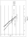
- Figure 8 displays example correlation curves for IR reflection (approx. 810 nm) from WB, comparing the HCT to the natural log of reflection (on the basis of Beer's law as explained in US 9,164,078 and US 6,419,822 ), for fluid flow rates of 10 ml/min, 50 ml/min, and 100 ml/min.
- the correlation curves represent experimental data which correlates the IR light reflected by blood to the HCT of the blood.
- Figure 9 displays an example correlation curve comparing flow rates to the natural log of light reflection for 40% HCT WB flowing through tubing 105'.
- the correlation is an exponential relationship, which is expected because there is a maximum number of cells that may be congregated in the viewing area of the reflection sensor, and as flow rates increase, the cell concentration change in the center streamlines begins tapering off as open space is taken up by cell content. Therefore, depending on the diameter of the tubing and the sensor viewing area, the method may be limited to a specific flow rate range. For example, when using relatively small diameter tubing, flow rates greater than 100 ml/min may not create significant changes in light reflection. However, use of a large diameter tubing and a sensor having a larger viewing area may permit detection of significant changes in light reflection at flow rates greater than 100 ml/min.
- a flow rate vs. LN (reflectance) correlation curve would be generated for every HCT in a desired range (ex: 35-55% for WB) and stored by the system (preprogrammed) for use based on the HCT value, which is the particulate value for the fluid that will be input by the user. Accordingly, correlation coefficients C1 and C2 will relate to respective correlation curves.
- Figure 10 displays a flow chart of the method logic.
- LN_Reflectance LN (Reflectance)
- Flow Rate C1e (C2 * LN Reflectance ). It will be appreciated that to continue to measure and monitor the flow rate, the process may be repeated.
- a durable or reusable fluid separation system is used in combination with a separate fluid flow circuit (which may be disposable) to separate a plasma-containing fluid into separated plasma and a concentrated fluid.
- a separate fluid flow circuit which may be disposable
- Figure 6 illustrates an exemplary fluid separation system 100
- Figure 7 illustrates a portion of an exemplary fluid flow cassette that may be used in a fluid processing system
- these are merely exemplary of such systems and circuits and that differently configured fluid processing systems and fluid flow circuits may be provided.
- system 100 of Figure 6 is configured for processing WB, it may be used to process any other plasma-containing fluid to separate plasma from concentrated fluid (which may be red cell concentrate or packed red cells when the plasma-containing fluid constitutes whole blood), and is merely representative of a fluid processing system utilizing an optical reflection sensor to measure fluid flow rate.
- concentrated fluid which may be red cell concentrate or packed red cells when the plasma-containing fluid constitutes whole blood
Landscapes
- Health & Medical Sciences (AREA)
- Physics & Mathematics (AREA)
- Fluid Mechanics (AREA)
- Heart & Thoracic Surgery (AREA)
- General Physics & Mathematics (AREA)
- Vascular Medicine (AREA)
- Anesthesiology (AREA)
- Engineering & Computer Science (AREA)
- Biomedical Technology (AREA)
- Hematology (AREA)
- Life Sciences & Earth Sciences (AREA)
- Animal Behavior & Ethology (AREA)
- General Health & Medical Sciences (AREA)
- Public Health (AREA)
- Veterinary Medicine (AREA)
- Electromagnetism (AREA)
- Cardiology (AREA)
- External Artificial Organs (AREA)
Claims (11)
- Vorrichtung zum Messen einer Fluiddurchflussrate unter Verwendung optischer Messungen und zur Verwendung in Kombination mit einem Schlauch (105; 114) in einem Fluidbehandlungssystem (100), umfassend:einen optischen Sensor (104; 120) mit einer Lichtquelle zum Emittieren von Licht, wobei mindestens ein Teil des Lichts einem durch den Schlauch strömenden Fluid ausgesetzt und reflektiert wird;wobei der optische Sensor ferner eine optische Faser (127; 128) zum Empfangen mindestens eines Teils des reflektierten Lichts umfasst;dadurch gekennzeichnet, dass die Vorrichtung umfasst:eine Steuerung (119), die dazu ausgelegt ist, das empfangene reflektierte Licht relativ zu zwei Korrelationskurvenkoeffizienten auf der Grundlage eines von einem Benutzer eingegebenen Partikelwerts zu korrelieren und eine Ausgabe zu berechnen, die die Durchflussrate des durch den Schlauch strömenden Fluids anzeigt,wobei die berechnete Ausgabe für die Durchflussrate gleich C1e (C2*LN Reflectance ) ist, worin C1 und C2 die beiden ausgewählten Korrelationskurvenkoeffizienten darstellen und LN Reflectance der berechnete natürliche Logarithmus ist, der sich auf den Reflexionsgrad der Partikel in dem Fluid bezieht.
- Vorrichtung nach Anspruch 1, wobei der optische Sensor ferner einen nichtinvasiven optischen Sensor umfasst.
- Vorrichtung nach einem der vorhergehenden Ansprüche, wobei der optische Sensor dazu ausgelegt ist, Infrarotlicht oder Breitbandlicht auszusenden und reflektiertes Licht zu erfassen.
- Vorrichtung nach einem der vorhergehenden Ansprüche in Kombination mit einem Fluidbehandlungssystem (100), ferner umfassend ein Apherese-Separations-System.
- Vorrichtung nach einem der vorhergehenden Ansprüche, wobei der Partikelwert ferner einen Hämatokritwert umfasst.
- Vorrichtung nach einem der vorhergehenden Ansprüche, wobei die Lichtquelle dazu ausgelegt ist, Infrarotlicht oder Breitbandlicht zu emittieren, das zumindest alle Wellenlängen im sichtbaren Bereich umfasst.
- Vorrichtung nach einem der vorhergehenden Ansprüche, wobei der optische Sensor dazu ausgelegt ist, mindestens einen Teil des reflektierten Lichts zu empfangen und mindestens einen Teil des empfangenen reflektierten Lichts zu analysieren, um eine Reflexionsgradmessung zu bestimmen.
- Vorrichtung nach Anspruch 7, wobei die Steuerung dazu ausgelegt ist, die Reflexionsgradmessung mit einem eingegebenen Partikelniveau zu korrelieren und eine Ausgabe zu erzeugen, die die Fluiddurchflussrate entsprechend der Reflexionsgradmessung anzeigt.
- Vorrichtung nach einem der vorhergehenden Ansprüche in Kombination mit einem Schlauch (105; 114) mit einer transparenten Oberfläche, wobei das von der Lichtquelle emittierte Licht durch die transparente Oberfläche des Schlauchs übertragen wird, um dem Fluid im Schlauch ausgesetzt zu werden, und der Reflexionsgrad des emittierten Lichts gemessen wird.
- Vorrichtung nach einem der Ansprüche 7 bis 8, wobei die Korrelation der Reflexionsgradmessung mit einer Partikelkonzentration ferner die Auswahl von zwei Korrelationskurvenkoeffizienten auf der Grundlage eines vom Benutzer eingegebenen Hämatokritwertes umfasst.
- Vorrichtung nach Anspruch 10, wobei das Erzeugen der Ausgabe, welche die der Reflexionsgradmessung entsprechende Durchflussrate anzeigt, ferner das Berechnen der Durchflussrate in Bezug auf die beiden Korrelationskurvenkoeffizienten und den natürlichen Logarithmus der Reflexionsgradmessung umfasst.
Applications Claiming Priority (1)
| Application Number | Priority Date | Filing Date | Title |
|---|---|---|---|
| US202163217588P | 2021-07-01 | 2021-07-01 |
Publications (3)
| Publication Number | Publication Date |
|---|---|
| EP4112094A1 EP4112094A1 (de) | 2023-01-04 |
| EP4112094B1 true EP4112094B1 (de) | 2025-05-21 |
| EP4112094C0 EP4112094C0 (de) | 2025-05-21 |
Family
ID=82403745
Family Applications (1)
| Application Number | Title | Priority Date | Filing Date |
|---|---|---|---|
| EP22181411.4A Active EP4112094B1 (de) | 2021-07-01 | 2022-06-28 | Optische vorrichtung und verfahren zur durchflussmessung |
Country Status (2)
| Country | Link |
|---|---|
| US (1) | US12385769B2 (de) |
| EP (1) | EP4112094B1 (de) |
Family Cites Families (20)
| Publication number | Priority date | Publication date | Assignee | Title |
|---|---|---|---|---|
| US2583908A (en) * | 1946-04-29 | 1952-01-29 | Frederick M Vonnegut | Brush ferrule |
| US2837237A (en) * | 1951-04-17 | 1958-06-03 | John M Stewart | Vending machine |
| JP3313841B2 (ja) | 1993-09-24 | 2002-08-12 | 興和株式会社 | 血流測定装置 |
| US6294094B1 (en) | 1999-09-03 | 2001-09-25 | Baxter International Inc. | Systems and methods for sensing red blood cell hematocrit |
| US7787923B2 (en) * | 2003-11-26 | 2010-08-31 | Becton, Dickinson And Company | Fiber optic device for sensing analytes and method of making same |
| WO2006006963A2 (en) * | 2004-04-02 | 2006-01-19 | The Government Of The United States Of America As Represented By The Secretary Of The Department Of Health And Human Services, Centers For Disease Control And Prevention | Aerosol delivery systems and methods |
| JP2009511023A (ja) * | 2005-10-06 | 2009-03-19 | ユニバーシティー、オブ、デラウェア | ハンチントン病の治療のためのgに富むポリヌクレオチド |
| WO2007105805A1 (ja) * | 2006-03-10 | 2007-09-20 | Kawasumi Laboratories, Inc. | 血液特性計測プローブ、循環器系人工臓器及び人工肺 |
| ITMI20090400A1 (it) | 2009-03-16 | 2010-09-17 | Datamed Srl | Metodo di misurazione della velocita' di un fluido e relativa apparecchiatura. |
| US20120002189A1 (en) * | 2009-03-18 | 2012-01-05 | Koninklijke Philips Electronics N.V. | Apparatus for determining a flow property of a fluid |
| DE102010012050B4 (de) * | 2010-03-19 | 2016-09-29 | Fresenius Medical Care Deutschland Gmbh | Hämodialysemaschine |
| US9374735B2 (en) * | 2012-04-13 | 2016-06-21 | Nokia Technologies Oy | Method and apparatus for data flow management |
| US9164078B2 (en) | 2012-06-15 | 2015-10-20 | Fenwal, Inc. | Process for predicting hematocrit of whole blood using IR light |
| JP6301696B2 (ja) | 2014-03-25 | 2018-03-28 | テルモ株式会社 | 流量センサ及び流量センサを備えた体外循環装置、及びその制御方法 |
| WO2016114264A1 (ja) * | 2015-01-13 | 2016-07-21 | 株式会社村田製作所 | 滴下量測定装置、滴下量コントローラ、点滴装置および液滴体積測定装置 |
| JP2017009535A (ja) * | 2015-06-25 | 2017-01-12 | 学校法人 中央大学 | 流速測定方法 |
| US10893829B2 (en) | 2018-04-13 | 2021-01-19 | Fenwal, Inc. | Optical detection and measurement of hematocrit and free hemoglobin concentration |
| CN112638442B (zh) * | 2018-06-29 | 2024-10-29 | 爱德芳世株式会社 | 经皮端子 |
| CN109924969A (zh) * | 2019-04-19 | 2019-06-25 | 优谱激光科技(南京)有限公司 | 一种具有轻便探头的激光成像血流灌注检测装置 |
| CN114659952B (zh) * | 2022-03-22 | 2025-03-25 | 武汉科技大学 | 一种近后向散射式车载颗粒物传感器及排气管 |
-
2022
- 2022-06-28 US US17/851,452 patent/US12385769B2/en active Active
- 2022-06-28 EP EP22181411.4A patent/EP4112094B1/de active Active
Also Published As
| Publication number | Publication date |
|---|---|
| EP4112094C0 (de) | 2025-05-21 |
| US12385769B2 (en) | 2025-08-12 |
| US20230003564A1 (en) | 2023-01-05 |
| EP4112094A1 (de) | 2023-01-04 |
Similar Documents
| Publication | Publication Date | Title |
|---|---|---|
| US9164078B2 (en) | Process for predicting hematocrit of whole blood using IR light | |
| JP4545364B2 (ja) | 光学濃度をモニターする血液処理システム | |
| EP3035054B1 (de) | Systeme und verfahren zur bestimmung des freien hämoglobins im plasma | |
| CN110799223B (zh) | 用于收集血浆的系统和方法 | |
| US7018353B2 (en) | Hematocrit sampling system | |
| EP3553498B1 (de) | Optische erfassung und messung von hämatokrit und freier hämoglobinkonzentration | |
| US8192386B2 (en) | System and method for controlling hematocrit during a therapeutic red blood cell exchange procedure | |
| JP2021500950A5 (de) | ||
| EP3578971A1 (de) | Bestimmung der ursache von rötung in einer biologischen flüssigkeit | |
| JP2001510171A (ja) | 血漿成分中に含まれる血小板量を光学的に導出する血液処理システムおよび方法 | |
| EP2730305B1 (de) | Citratdetektor für Blutverarbeitungssystem | |
| US9919092B2 (en) | Optical detection of lipids | |
| US12385769B2 (en) | Optical device and method for measuring flow rate | |
| EP2788043B1 (de) | Verfahren und vorrichtungzur vorzählung von spendertrhombozyten bei einem zentrifugalen blutabscheider | |
| HK40021259A (en) | System and method for collecting plasma | |
| HK40021259B (en) | System and method for collecting plasma |
Legal Events
| Date | Code | Title | Description |
|---|---|---|---|
| PUAI | Public reference made under article 153(3) epc to a published international application that has entered the european phase |
Free format text: ORIGINAL CODE: 0009012 |
|
| STAA | Information on the status of an ep patent application or granted ep patent |
Free format text: STATUS: THE APPLICATION HAS BEEN PUBLISHED |
|
| AK | Designated contracting states |
Kind code of ref document: A1 Designated state(s): AL AT BE BG CH CY CZ DE DK EE ES FI FR GB GR HR HU IE IS IT LI LT LU LV MC MK MT NL NO PL PT RO RS SE SI SK SM TR |
|
| STAA | Information on the status of an ep patent application or granted ep patent |
Free format text: STATUS: REQUEST FOR EXAMINATION WAS MADE |
|
| 17P | Request for examination filed |
Effective date: 20230629 |
|
| RBV | Designated contracting states (corrected) |
Designated state(s): AL AT BE BG CH CY CZ DE DK EE ES FI FR GB GR HR HU IE IS IT LI LT LU LV MC MK MT NL NO PL PT RO RS SE SI SK SM TR |
|
| GRAP | Despatch of communication of intention to grant a patent |
Free format text: ORIGINAL CODE: EPIDOSNIGR1 |
|
| STAA | Information on the status of an ep patent application or granted ep patent |
Free format text: STATUS: GRANT OF PATENT IS INTENDED |
|
| INTG | Intention to grant announced |
Effective date: 20241223 |
|
| RIN1 | Information on inventor provided before grant (corrected) |
Inventor name: KUSTERS, BENJAMIN E. |
|
| GRAS | Grant fee paid |
Free format text: ORIGINAL CODE: EPIDOSNIGR3 |
|
| GRAA | (expected) grant |
Free format text: ORIGINAL CODE: 0009210 |
|
| STAA | Information on the status of an ep patent application or granted ep patent |
Free format text: STATUS: THE PATENT HAS BEEN GRANTED |
|
| AK | Designated contracting states |
Kind code of ref document: B1 Designated state(s): AL AT BE BG CH CY CZ DE DK EE ES FI FR GB GR HR HU IE IS IT LI LT LU LV MC MK MT NL NO PL PT RO RS SE SI SK SM TR |
|
| REG | Reference to a national code |
Ref country code: GB Ref legal event code: FG4D |
|
| REG | Reference to a national code |
Ref country code: CH Ref legal event code: EP |
|
| REG | Reference to a national code |
Ref country code: DE Ref legal event code: R096 Ref document number: 602022014855 Country of ref document: DE |
|
| REG | Reference to a national code |
Ref country code: IE Ref legal event code: FG4D |
|
| U01 | Request for unitary effect filed |
Effective date: 20250610 |
|
| U07 | Unitary effect registered |
Designated state(s): AT BE BG DE DK EE FI FR IT LT LU LV MT NL PT RO SE SI Effective date: 20250617 |
|
| PGFP | Annual fee paid to national office [announced via postgrant information from national office to epo] |
Ref country code: AT Payment date: 20250721 Year of fee payment: 4 |
|
| U20 | Renewal fee for the european patent with unitary effect paid |
Year of fee payment: 4 Effective date: 20250628 |
|
| PG25 | Lapsed in a contracting state [announced via postgrant information from national office to epo] |
Ref country code: ES Free format text: LAPSE BECAUSE OF FAILURE TO SUBMIT A TRANSLATION OF THE DESCRIPTION OR TO PAY THE FEE WITHIN THE PRESCRIBED TIME-LIMIT Effective date: 20250521 |
|
| PG25 | Lapsed in a contracting state [announced via postgrant information from national office to epo] |
Ref country code: GR Free format text: LAPSE BECAUSE OF FAILURE TO SUBMIT A TRANSLATION OF THE DESCRIPTION OR TO PAY THE FEE WITHIN THE PRESCRIBED TIME-LIMIT Effective date: 20250822 Ref country code: NO Free format text: LAPSE BECAUSE OF FAILURE TO SUBMIT A TRANSLATION OF THE DESCRIPTION OR TO PAY THE FEE WITHIN THE PRESCRIBED TIME-LIMIT Effective date: 20250821 |
|
| PG25 | Lapsed in a contracting state [announced via postgrant information from national office to epo] |
Ref country code: PL Free format text: LAPSE BECAUSE OF FAILURE TO SUBMIT A TRANSLATION OF THE DESCRIPTION OR TO PAY THE FEE WITHIN THE PRESCRIBED TIME-LIMIT Effective date: 20250521 |
|
| PG25 | Lapsed in a contracting state [announced via postgrant information from national office to epo] |
Ref country code: HR Free format text: LAPSE BECAUSE OF FAILURE TO SUBMIT A TRANSLATION OF THE DESCRIPTION OR TO PAY THE FEE WITHIN THE PRESCRIBED TIME-LIMIT Effective date: 20250521 |
|
| PG25 | Lapsed in a contracting state [announced via postgrant information from national office to epo] |
Ref country code: RS Free format text: LAPSE BECAUSE OF FAILURE TO SUBMIT A TRANSLATION OF THE DESCRIPTION OR TO PAY THE FEE WITHIN THE PRESCRIBED TIME-LIMIT Effective date: 20250821 |
|
| PG25 | Lapsed in a contracting state [announced via postgrant information from national office to epo] |
Ref country code: IS Free format text: LAPSE BECAUSE OF FAILURE TO SUBMIT A TRANSLATION OF THE DESCRIPTION OR TO PAY THE FEE WITHIN THE PRESCRIBED TIME-LIMIT Effective date: 20250921 |
|
| PG25 | Lapsed in a contracting state [announced via postgrant information from national office to epo] |
Ref country code: SM Free format text: LAPSE BECAUSE OF FAILURE TO SUBMIT A TRANSLATION OF THE DESCRIPTION OR TO PAY THE FEE WITHIN THE PRESCRIBED TIME-LIMIT Effective date: 20250521 |
|
| PG25 | Lapsed in a contracting state [announced via postgrant information from national office to epo] |
Ref country code: CZ Free format text: LAPSE BECAUSE OF FAILURE TO SUBMIT A TRANSLATION OF THE DESCRIPTION OR TO PAY THE FEE WITHIN THE PRESCRIBED TIME-LIMIT Effective date: 20250521 |
|
| PG25 | Lapsed in a contracting state [announced via postgrant information from national office to epo] |
Ref country code: SK Free format text: LAPSE BECAUSE OF FAILURE TO SUBMIT A TRANSLATION OF THE DESCRIPTION OR TO PAY THE FEE WITHIN THE PRESCRIBED TIME-LIMIT Effective date: 20250521 |
|
| REG | Reference to a national code |
Ref country code: CH Ref legal event code: H13 Free format text: ST27 STATUS EVENT CODE: U-0-0-H10-H13 (AS PROVIDED BY THE NATIONAL OFFICE) Effective date: 20260127 |
|
| PG25 | Lapsed in a contracting state [announced via postgrant information from national office to epo] |
Ref country code: MC Free format text: LAPSE BECAUSE OF FAILURE TO SUBMIT A TRANSLATION OF THE DESCRIPTION OR TO PAY THE FEE WITHIN THE PRESCRIBED TIME-LIMIT Effective date: 20250521 |
|
| PLBE | No opposition filed within time limit |
Free format text: ORIGINAL CODE: 0009261 |
|
| STAA | Information on the status of an ep patent application or granted ep patent |
Free format text: STATUS: NO OPPOSITION FILED WITHIN TIME LIMIT |
|
| REG | Reference to a national code |
Ref country code: CH Ref legal event code: L10 Free format text: ST27 STATUS EVENT CODE: U-0-0-L10-L00 (AS PROVIDED BY THE NATIONAL OFFICE) Effective date: 20260402 |
|
| PG25 | Lapsed in a contracting state [announced via postgrant information from national office to epo] |
Ref country code: IE Free format text: LAPSE BECAUSE OF NON-PAYMENT OF DUE FEES Effective date: 20250628 |
|
| PG25 | Lapsed in a contracting state [announced via postgrant information from national office to epo] |
Ref country code: CH Free format text: LAPSE BECAUSE OF NON-PAYMENT OF DUE FEES Effective date: 20250630 |
|
| 26N | No opposition filed |
Effective date: 20260224 |