EP4112191B1 - Actionneur de vibration et dispositif électronique - Google Patents
Actionneur de vibration et dispositif électronique Download PDFInfo
- Publication number
- EP4112191B1 EP4112191B1 EP21761712.5A EP21761712A EP4112191B1 EP 4112191 B1 EP4112191 B1 EP 4112191B1 EP 21761712 A EP21761712 A EP 21761712A EP 4112191 B1 EP4112191 B1 EP 4112191B1
- Authority
- EP
- European Patent Office
- Prior art keywords
- vibration
- movable body
- vibration actuator
- movable
- elastic supporting
- Prior art date
- Legal status (The legal status is an assumption and is not a legal conclusion. Google has not performed a legal analysis and makes no representation as to the accuracy of the status listed.)
- Active
Links
Images





















Classifications
-
- B—PERFORMING OPERATIONS; TRANSPORTING
- B06—GENERATING OR TRANSMITTING MECHANICAL VIBRATIONS IN GENERAL
- B06B—METHODS OR APPARATUS FOR GENERATING OR TRANSMITTING MECHANICAL VIBRATIONS OF INFRASONIC, SONIC, OR ULTRASONIC FREQUENCY, e.g. FOR PERFORMING MECHANICAL WORK IN GENERAL
- B06B1/00—Methods or apparatus for generating mechanical vibrations of infrasonic, sonic, or ultrasonic frequency
- B06B1/02—Methods or apparatus for generating mechanical vibrations of infrasonic, sonic, or ultrasonic frequency making use of electrical energy
- B06B1/04—Methods or apparatus for generating mechanical vibrations of infrasonic, sonic, or ultrasonic frequency making use of electrical energy operating with electromagnetism
- B06B1/045—Methods or apparatus for generating mechanical vibrations of infrasonic, sonic, or ultrasonic frequency making use of electrical energy operating with electromagnetism using vibrating magnet, armature or coil system
-
- B—PERFORMING OPERATIONS; TRANSPORTING
- B06—GENERATING OR TRANSMITTING MECHANICAL VIBRATIONS IN GENERAL
- B06B—METHODS OR APPARATUS FOR GENERATING OR TRANSMITTING MECHANICAL VIBRATIONS OF INFRASONIC, SONIC, OR ULTRASONIC FREQUENCY, e.g. FOR PERFORMING MECHANICAL WORK IN GENERAL
- B06B1/00—Methods or apparatus for generating mechanical vibrations of infrasonic, sonic, or ultrasonic frequency
- B06B1/02—Methods or apparatus for generating mechanical vibrations of infrasonic, sonic, or ultrasonic frequency making use of electrical energy
- B06B1/04—Methods or apparatus for generating mechanical vibrations of infrasonic, sonic, or ultrasonic frequency making use of electrical energy operating with electromagnetism
-
- B—PERFORMING OPERATIONS; TRANSPORTING
- B06—GENERATING OR TRANSMITTING MECHANICAL VIBRATIONS IN GENERAL
- B06B—METHODS OR APPARATUS FOR GENERATING OR TRANSMITTING MECHANICAL VIBRATIONS OF INFRASONIC, SONIC, OR ULTRASONIC FREQUENCY, e.g. FOR PERFORMING MECHANICAL WORK IN GENERAL
- B06B1/00—Methods or apparatus for generating mechanical vibrations of infrasonic, sonic, or ultrasonic frequency
- B06B1/02—Methods or apparatus for generating mechanical vibrations of infrasonic, sonic, or ultrasonic frequency making use of electrical energy
- B06B1/0207—Driving circuits
- B06B1/0223—Driving circuits for generating signals continuous in time
-
- B—PERFORMING OPERATIONS; TRANSPORTING
- B06—GENERATING OR TRANSMITTING MECHANICAL VIBRATIONS IN GENERAL
- B06B—METHODS OR APPARATUS FOR GENERATING OR TRANSMITTING MECHANICAL VIBRATIONS OF INFRASONIC, SONIC, OR ULTRASONIC FREQUENCY, e.g. FOR PERFORMING MECHANICAL WORK IN GENERAL
- B06B1/00—Methods or apparatus for generating mechanical vibrations of infrasonic, sonic, or ultrasonic frequency
- B06B1/10—Methods or apparatus for generating mechanical vibrations of infrasonic, sonic, or ultrasonic frequency making use of mechanical energy
- B06B1/12—Methods or apparatus for generating mechanical vibrations of infrasonic, sonic, or ultrasonic frequency making use of mechanical energy operating with systems involving reciprocating masses
- B06B1/14—Methods or apparatus for generating mechanical vibrations of infrasonic, sonic, or ultrasonic frequency making use of mechanical energy operating with systems involving reciprocating masses the masses being elastically coupled
-
- H—ELECTRICITY
- H02—GENERATION; CONVERSION OR DISTRIBUTION OF ELECTRIC POWER
- H02K—DYNAMO-ELECTRIC MACHINES
- H02K33/00—Motors with reciprocating, oscillating or vibrating magnet, armature or coil system
- H02K33/02—Motors with reciprocating, oscillating or vibrating magnet, armature or coil system with armatures moved one way by energisation of a single coil system and returned by mechanical force, e.g. by springs
-
- H—ELECTRICITY
- H02—GENERATION; CONVERSION OR DISTRIBUTION OF ELECTRIC POWER
- H02K—DYNAMO-ELECTRIC MACHINES
- H02K33/00—Motors with reciprocating, oscillating or vibrating magnet, armature or coil system
- H02K33/16—Motors with reciprocating, oscillating or vibrating magnet, armature or coil system with polarised armatures moving in alternate directions by reversal or energisation of a single coil system
Definitions
- the present invention relates to a vibration actuator and an electronic device including the vibration actuator.
- a vibration actuator used in a pager or the like as disclosed in Patent Literature (hereinafter, referred to as "PTL") 1 has been known as a vibration actuator of a miniaturizable structure mounted on a portable device, for example.
- Document US 5 682 132 A discloses a vibrating module for generating a mainly non-audible alert signal comprises a vibrating mass supported by at least one spring and having a weight and a magnet.
- a drive coil is supported by a coil frame for placing the vibrating mass in a continuous reciprocating motion close to a resonant frequency determined by the vibrating mass and the spring.
- An electrical signal supplying device supplies an electrical signal to the drive coil to vibrate the vibrating mass in a linear reciprocating motion.
- Document WO 2019/130705 A1 discloses a further vibration actuator with a simple structure.
- a first and second dampers are disposed as leaf springs so that spiral arm sections of the first damper and spiral arm sections of the second damper have opposite spiral directions.
- the arm sections of the first and the second damper include stress concentration portions where stress increases locally at the time of force loading thereon.
- Vibration actuator 1 is mounted as a vibration source on an electronic device such as a portable game terminal device (for example, game controller GC illustrated in FIG. 28 ) to implement a vibrating function of the electronic device.
- a portable game terminal device for example, game controller GC illustrated in FIG. 28
- a portable device such as a smart phone (for example, mobile terminal M illustrated in FIG. 29 ).
- Vibration actuator 1 is mounted on a device such as a portable game terminal device or a portable device, and is driven to vibrate to notify a user of an incoming call or to give an operational feel or realism.
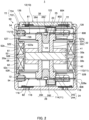
- movable body 20 is supported inside cylindrical coil bobbin part 52 of fixing body 50 by elastic supporting parts 81 and 82 connected to the upper and lower end portions of the movable body, such that the movable body is capable of reciprocating along coil bobbin part 52 (inner circumferential surface 522a of bobbin main-body portion 522).
- movable body 20 is supported to be capable of reciprocating in a direction in which lid portion 12 and bottom portion 114 face each other.
- Movable body 20 is disposed in driving unit 13 illustrated in FIG. 3 .
- Movable body 20 and elastic supporting parts 81 and 82 are joined to each other by sealing part 90 without any gap.
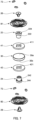
- Movable body 20 includes magnet 30, movable-body cores 41 and 42, spring retaining parts 22 and 24, and fixation pins 26 and 28 as illustrated in FIGS. 2 and 5 to 7 .
- movable-body cores 41 and 42 and spring retaining parts 22 and 24 are continuously disposed respectively toward opposite sides from magnet 30 in the vibration direction (in the upper-lower direction in FIGS. 1 to 3 and 5 to 7 ).
- movable body 20 When movable body 20 moves in the vibration direction, movable body 20 reciprocates along inner circumferential surface 522a such that outer circumferential surface 20a does not make contact with inner circumferential surface 522a.
- Magnet 30 is magnetized in the vibration direction. Magnet 30 is formed in a disk shape in the present embodiment, and front and back surfaces 30a and 30b separate from each other in the vibration direction respectively have different poles. Front and back surfaces 30a and 30b of magnet 30 are two magnetized surfaces separate from each other in the extending direction of the axes of coils 61 and 62.
- Magnet 30 is disposed radially inside coils 61 and 62 (described in detail below) with a gap being interposed between the magnet and coils 61 and 62.
- radially (radial direction) means a direction orthogonal to the axes of coils 61 and 62, and also means the direction orthogonal to the vibration direction.
- This "gap" in the radial direction is a gap between magnet 30 and coils 61 and 62 including bobbin main-body portion 522, and is a gap allowing movable body 20 to move in the vibration direction of movable body 20 such that magnet 30 and coils 61 and 62 do not make contact with each other. That is, the "gap” means a predetermined gap between bobbin main-body portion 522 and magnet 30 in the present embodiment.
- movable-body cores 41 and 42 in movable body 20 have a function as a main-body part of movable body 20, a function of fixing spring retaining parts 22 and 24, and a function as a weight.
- movable-body cores 41 and 42 are formed in an annular flat plate shape having the same surface shape as magnet 30. Movable-body cores 41 and 42 are fixed to magnet 30 such that the outer circumferential surfaces of movable-body cores 41 and 42 are flush with the outer circumferential surface of the magnet, and forms outer circumferential surface 20a of movable body 20 together with the outer circumferential surface of the magnet.
- Movable-body cores 41 and 42 are the same similarly-formed members in the present embodiment, and are symmetrically disposed above and below magnet 30 so as to sandwich magnet 30. Note that, movable-body cores 41 and 42 are attracted to magnet 30, and also are fixed to magnet 30, for example, by a thermosetting adhesive such as an epoxy resin or an anaerobic adhesive.
- Fitting openings 411 and 421 to which upper and lower spring retaining parts 22 and 24 are fitted are formed in the respective central portions of movable-body cores 41 and 42. Upper and lower spring retaining parts 22 and 24 are inserted in fitting openings 411 and 421.
- Movable-body cores 41 and 42 make contact with spring retaining parts 22 and 24 at three or four points in fitting openings 411 and 421 to support the spring retaining parts such that the axis of each of upper and lower spring retaining parts 22 and 24 (here, coincides with the center of elastic supporting parts 81 and 82) is positioned on the central axis of movable body 20.
- fitting openings 411 and 421 the degrees of openings in movable-body cores 41 and 42 are adjustable for adjusting the weight of movable body 20, so that a preferable vibration output can be set.
- movable-body cores 41 and 42 are located inside (radially inside) coils 61 and 62 to respectively face coils 61 and 62 in the direction orthogonal to the axial direction of coils 61 and 62 in the non-vibration state of movable body 20.
- movable-body cores 41 and 42 it is preferable that the height position of the upper surface of movable-body core 41 on the upper side of magnet 30 face the position of the center of upper coil 61 in the height direction (upper-lower direction). In addition, it is preferable that the height position of the lower surface of movable-body core 42 on the lower side of magnet 30 face the position of the center of lower coil 62 in the height direction (upper-lower direction).
- Spring retaining parts 22 and 24 have a function of fixing the movable-body-side magnetic circuit to elastic supporting parts 81 and 82, and a function as a weight of movable body 20.
- Spring retaining parts 22 and 24 are symmetrically disposed to sandwich magnet 30 and movable-body cores 41 and 42, and increase the vibration output of movable body 20.
- FIG. 8 is a perspective view of spring retaining part 22 (24) as seen from the spring fixation portion 224 (244) side.
- spring retaining parts 22 and 24 are formed in the same shape.
- the reference numerals are described as "spring retaining part 22 (24).”
- Spring retaining part 22 will be mainly described, and description of spring retaining part 24 will be omitted.
- Spring retaining parts 22 and 24 are a shaft-like body disposed along the central axis of movable body 20 in the present embodiment, and are interposed between movable-body cores 41 and 42 and elastic supporting parts 81 and 82.
- Spring retaining parts 22 and 24 are formed in the same shape in the present embodiment, and have joint portions 222 and 242 and spring fixation portions 224 and 244. These joint portions 222 and 242 and spring fixation portions 224 and 244 are continuously formed in the vibration direction (specifically, in the upper-lower direction).
- Each of spring retaining parts 22 and 24 is a cylindrical body, and has through hole 23 extending through the inside of the spring retaining part. Note that, spring retaining parts 22 and 24 function as a weight. Further, spring retaining parts 22 and 24 may function as a weight adjusting part that adjusts the weight by addition of a weight in through hole 23. It is possible to increase the vibration output of movable body 20 by making movable body 20 heavier by adding a weight in through hole 23.
- Joint portions 222 and 242 are joined to movable-body cores 41 and 42, respectively.
- Joint portions 222 and 242 are cylindrical bodies disposed on the axis of movable body 20.
- Joint portions 222 and 242 are joined to movable-body cores 41 and 42 by inserting the other end portion sides thereof into fitting openings 411 and 421 in movable-body cores 41 and 42, respectively, and by fitting them internally.
- Spring retaining parts 22 and 24 are fixed to movable-body cores 41 and 42 by press-fitting in the present embodiment, but the present invention is not limited thereto, and spring retaining parts 22 and 24 may also be fixed, for example, by adhesion using a thermosetting adhesive such as epoxy resin or an anaerobic adhesive.
- joint portions 222 and 242 are formed as cylindrical bodies, they may be formed as solid cylindrical bodies, or may be formed as rod-shaped bodies having recessed portions along the axis.
- Upper spring fixation portion 224 forms one end portion of movable body 20 in the vibration direction, that is, the upper end portion of movable body 20.
- Spring fixation portion 224 is disposed to protrude from joint portion 222 on one side (upward) in spring retaining part 22, and is a cylindrical body having a larger outer diameter than joint portion 222.
- through hole 23 opens at a front end (upper end) surface (hereinafter, also referred to as "joining surface") 224a thereof.
- Spring fixation portion 224 together with fixation pin 26 inserted into through hole 23, holds inner circumferential portion 802 in a state in which inner circumferential portion 802, which is an inner-diameter-side end portion of the upper leaf spring as elastic supporting part 81, is in contact with joining surface 224a.
- spring fixation portion 224 and elastic supporting part 81 are joined to each other.
- lower spring fixation portion 244 forms the other end portion of movable body 20 in the vibration direction, i.e., the lower end portion of movable body 20 as illustrated in FIG. 6 .
- Spring fixation portion 244 is joined to inner circumferential portion 802, which is an inner-diameter-side end portion of the lower leaf spring as elastic supporting part 82.
- Spring fixation portion 244 is disposed to protrude from joint portion 242 on the other side (downward) in spring retaining part 24, and is a cylindrical body having a larger outer diameter than joint portion 242.
- through hole 23 opens in joining surface 244a which is a front end (lower end) surface.
- Spring fixation portion 244 together with fixation pin 28 inserted into through hole 23, holds inner circumferential portion 802 in a state in which inner circumferential portion 802 of the lower leaf spring serving as elastic supporting part 82 is in contact with joining surface 244a.
- spring fixation portion 244 and elastic supporting part 82 are joined to each other.
- a detailed description of elastic supporting part 81 including inner circumferential portion 802 will be given later with description of elastic supporting part 82.
- each of spring fixation portions 224 and 244 is provided with recess forming portion 25 that forms a continuous depression in joining surface 224a.
- Recess forming portion 25 forms a space continuous with joining surface 224a between the recess forming portion and elastic supporting part 81 as illustrated in FIGS. 2 and 6 .
- Recess forming portion 25 is formed by cutting out an inner circumferential edge portion of annular joining surface 224a of spring fixation portion 224. Recess forming portion 25 stores in joining surface 224a a sealing material serving as sealing part 90, such as an adhesive, a gap with respect to inner circumferential portion 802, to join spring retaining part 22 to elastic supporting part 81.
- a sealing material serving as sealing part 90 such as an adhesive
- Fixation pins 26 and 28 firmly fix together elastic supporting parts 81 and 82 and movable body 20 such that they do not come off each other by the vibration of movable body 20.
- FIG. 9 is a perspective view of fixation pin 26 (28) as viewed from the pin body 262 (282) side.
- Fixation pins 26 and 28 are for fixing elastic supporting parts 81 and 82 to spring retaining parts 22 and 24.
- fixation pins 26 and 28 are formed in the same shape.
- Fixation pins 26 and 28 respectively include shaft-shaped pin bodies 262 and 282 which can be press-fitted into spring fixation portions 224 and 244, flanges 264 and 284 disposed on the edge portions of one end sides of pin bodies 262 and 282, and annular grooves 27 and 27.
- Fixation pin 26 (28) may be a rivet such as a blind rivet.
- Pin bodies 262 and 282 of fixation pins 26 and 28 are inserted respectively into through holes 23 in spring fixation portions 224 and 244 (specifically, press-fitted by caulking) and are fixed to spring fixation portions 224 and 244.
- Annular grooves 27 are continuously formed in the surfaces of flanges 264 and 284 which are to make contact with inner circumferential portions 802. Annular grooves 27 are formed, for example, in flanges 264 and 284 along the outer circumferences of the base end portions of pin bodies 262 and 282 rising from the central portion of flanges 264 and 284. Sealing part 90 for closing gaps is disposed in annular grooves 27 in case that there are gaps between spring fixation portions 224 and 244, fixation pins 26 and 28, and inner circumferential portions 802.
- the weight in movable body 20 does not need to be disposed on the outer circumferential side of the movable-body magnetic circuit.
- the arrangement space for coils 61 and 62 located to face each other on the outer circumferential side of the movable-body-side magnetic circuit i.e., on the outer circumferential side of movable body 20
- the distance between the movable-body magnetic circuit and coils 61 and 62 does not increase, so that the efficiency in electromagnetic conversion is not reduced. Accordingly, it is possible to preferably increase the weight of movable body 20, so as to achieve a higher vibration output.
- spring retaining parts 22 and 24 have the function as a weight and the function of spring fixation, it is not necessary to assemble separate members respectively having these functions. Only by disposing spring retaining parts 22 and 24 in the movable-body-side magnetic circuit, the weight and the upper and lower leaf springs being elastic supporting parts 81 and 82 can be easily attached to movable body 20, so that the assemblability is enhanced.
- spring retaining parts 22 and 24 may be formed from a magnetic material, it is desirable that spring retaining parts 22 and 24 be formed from a non-magnetic material.
- spring retaining parts 22 and 24 are formed from a non-magnetic material, no magnetic flux from movable-body core 41 flows upward and no magnetic flux from movable-body core 42 flows downward, so that it is possible to cause the magnetic flux to flow toward coils 61 and 62 located on the outer circumferential side of movable-body cores 41 and 42 efficiently.
- spring retaining parts 22 and 24 be formed from a material having a higher specific gravity (e.g., the specific gravity as high as about 16 to 19) than a material of a silicon steel plate or the like (the specific gravity of the steel plate is 7.70 to 7.98).
- tungsten can be applied as the material of spring retaining parts 22 and 24.
- Elastic supporting parts 81 and 82 support movable body 20 such that the movable body freely reciprocates in the vibration direction with respect to fixing body 50.
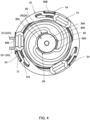
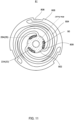
- FIGS. 10 and 11 are a perspective view and a plan view of movable body 20 to which elastic supporting parts 81 and 82 are joined. As illustrated in FIGS. 2 , 3 , 5 , 6 , 10 , and 11 , elastic supporting parts 81 and 82 sandwich movable body 20 in the vibration direction of movable body 20 and are disposed on both movable body 20 and fixing body 50 to intersect the vibration direction.
- Elastic supporting parts 81 and 82 may be a non-magnetic material or a magnetic material (specifically, a ferromagnetic material). Elastic supporting parts 81 and 82 may be made using a stainless steel plate such as SUS304 or SUS316 when the elastic supporting parts are the leaf springs of a non-magnetic material. Further, when elastic supporting parts 81 and 82 are a magnetic material, a stainless steel plate such as SUS301 can be applied. It is known that a magnetic material (e.g., SUS301) is more durable and less expensive than a non-magnetic material (e.g., SUS304, SUS316) as a material of elastic supporting parts 81 and 82. In the present embodiment, elastic supporting parts 81 and 82 are formed of SUS301.
- Elastic supporting parts 81 and 82 are formed by sheet metal processing using a stainless steel plate, and more specifically, are formed into thin flat disk-shaped whirl-shaped springs. Since elastic supporting parts 81 and 82 are flat plate-like, it is possible to improve the positional accuracy, that is, to improve the processing accuracy as compared with a conical spring.
- Elastic supporting parts 81 and 82 of the present embodiment are fixed to movable body 20 such that the whirl directions are the same.
- elastic supporting parts 81 and 82 can move smoothly, i.e., can be deformed to produce a greater amplitude, so that the vibration output can be increased.
- the whirl directions of the plurality of elastic supporting parts 81 and 82 may be designed to be opposite directions to each other.
- upper end surface 527a means an upper (one-side) end surface of the portion of the upper side (one side) of upper (one-side) flange portion 527 other than movable-range forming parts 54.
- lower end surface 528a means an upper (other-side) end surface of the portion of the lower side (other side) of lower (other-side) flange portion 528 other than movable-range forming parts 54.
- Sealing part 90 may be formed of, for example, a material that allows welding, bonding, caulking, or the like, or may be formed by combining these materials as appropriate.
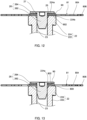
- sealing part 90 is disposed in recessed portions 809 in elastic supporting part 81 to fill recessed portions 809. That is, sealing part 90 is disposed in a solid state so as to fill the insides of recessed portions 809 and the gaps between elastic supporting part 81 and fixation pin 26.
- the sealing part achieves tight joining of each part with which the sealing part makes contact. Thus, it is possible to firmly join fixation pin 26 and spring retaining part 22 sandwiching elastic supporting part 81.
- vibration actuator 1 the gaps between elastic supporting parts 81 and 82 being leaf springs and movable body 20 (mainly spring retaining parts 22 and 24 and fixation pins 26 and 28) are sealed via sealing part 90.
- Vibration actuator 1 can realize a vibration of high output with high quietness and stability. Further, it is possible to make it less likely for a coupling state of the movable body and elastic supporting parts 81 and 82 to be weakened due to aging via the gaps due to the movement of movable body 20 and the deformation of elastic supporting parts 81 and 82 during vibration, and it is possible to prevent a driving noise generated by mutual contact.
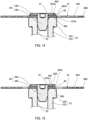
- FIGS. 14 and 15 are diagrams illustrating Variation 1 of the joint structure of the elastic supporting part and the movable body.
- FIG. 14 corresponds to the figure illustrated in FIG. 12
- FIG. 15 corresponds to the portion illustrated in FIG. 13 .
- sealing part 90A includes outer circumferential surface 92 covering outer circumferential surface 2642 of flange 264 (the side surface of the upper end portion of fixation pin 26) as well as the gaps between elastic supporting part 81 and flange 264 of fixation pin 26. Sealing part 90A is disposed in a fillet shape, and outer circumferential surface 92 is a fillet-shaped surface curved concavely.
- a portion of sealing part 90A disposed in recessed portions 809 extends on the outer circumferential surface 2642 side of fixation pin 26 in the axial direction, and covers outer circumferential surface 2642. Therefore, the portion of sealing part 90A in recessed portions 809 is disposed to straddle between joining surface 224a of spring retaining part 22 and outer circumferential surface 2642 of flange 264 of fixation pin 26, and closes the gaps between elastic supporting part 81, fixation pin 26, and spring retaining part 22. Note that, the gaps between elastic supporting part 82, fixation pin 28, and spring retaining part 24 are also closed by the same sealing part as sealing part 90A. Thus, it is possible to obtain the same effects as the effects obtained by sealing part 90.
- FIGS. 16 and 17 are explanatory views of Variation 2 of the joint structure of the elastic supporting part and the movable body.
- gap G2 may be generated between inner circumferential portion 802 and joining surface 224a of spring retaining part 22.
- elastic supporting part 81 and movable body 20 are sealed without any gap by sealing parts 90B and 90C as illustrated in FIG. 17 .
- Sealing part 90B is the same as sealing part 90 of the present embodiment and is disposed in gap G1 between fixation pin 26 and elastic supporting part 81 (inner circumferential portion 802). Sealing part 90B completely closes gap G1 between fixation pin 26 and elastic supporting part 81, and joins both of them together. Sealing part 90B is also disposed in annular groove 27. Note that, outer surface 92B of sealing part 90B between elastic supporting part 81 and fixation pin 26 is curved concavely.
- Sealing part 90C is disposed in gap G2 between, on one hand, elastic supporting part 81 (inner circumferential portion 802) and, one the other hand, joining surface 224a of spring retaining part 22 and outer circumferential surface (chamfered portion) 224b of joining surface 224a.
- Sealing part 90C is disposed in a gap between spring retaining part 22 and elastic supporting part 81 (inner circumferential portion 802) in a solid state, fills gap G2, and joins elastic supporting part 81 (inner circumferential portion 802) to spring retaining part 22 without any gap.
- Each of sealing parts 90B and 90C is formed, for example, by sandwiching and fixing elastic supporting part 81 (inner circumferential portion 802) between spring retaining part 22 and fixation pin 26, and then filling, with an adhesive, spaces between spring retaining part 22 and fixation pin 26 that sandwich elastic supporting part 81 including recessed portions 809.
- the adhesive that fills recessed portions 809 penetrates on both sides between elastic supporting part 81 and each of flange 264 of fixation pin 26 and joining surface 224a to fill the recessed portions.
- the adhesive penetrates to recess forming portion 25, and accumulates in recess forming portion 25. Then, the adhesive is cured, whereby elastic supporting part 81, fixation pin 26, and spring retaining part 22 are sealed without any gap.
- sealing part 90C has a configuration in which the thickness between a portion of each of outer circumferential surface 224b and recessed-portion forming portion 25 and inner circumferential portion 802 is greater than the thickness of a portion between joining surface 224a and inner circumferential portion 802.
- sealing parts 90B and 90C can externally seal the gaps between spring retaining parts 22 and 24, elastic supporting parts 81 and 82, and fixation pins 26 and 28 which are fixed to one another. Therefore, it is possible to securely fill the gaps between spring retaining parts 22 and 24, elastic supporting parts 81 and 82, and fixation pins 26 and 28, and to suppress variations in the joint portion due to the manufacturing process.
- the adhesive serving as sealing parts 90B and 90C is applied to recessed portions 809, the adhesive permeates and fills the gaps between elastic supporting parts 81 and 82, fixation pins 26 and 28, and spring retaining parts 22 and 24 from recessed portions 809 at a time. As a result, the gaps on the front and back surface sides of elastic supporting parts 81 and 82 are reliably sealed.
- FIG. 18 is a partially enlarged view illustrating Variation 3 of the joint structure of elastic supporting part 81 and movable body 20.
- gaps are formed on the front and back surface sides of inner circumferential portion 802 of elastic supporting part 81 and fixation pin 26.
- sealing part 90D has outer circumferential surface 92 covering outer circumferential surface 2642 of fixation pin 26 (in particular, of flange 264).
- fixation pin 26 in particular, of flange 264
- FIG. 19 is an explanatory view of Variation 4 of the joint structure of the elastic supporting part and the movable body.
- sealing part 90 (see FIGS. 12 and 14 ) disposed in the gaps between elastic supporting part 81 and fixation pin 26 (flange 264) is made of elastomer 90E.
- Elastomer 90E functions as a sealing part, and closes and seals a gap between elastic supporting part 81 and fixation pin 26 (flange 264).
- Elastomer 90E may be pressed and deformed when elastic supporting part 81 is sandwiched between spring retaining part 22 and fixation pins 26, and may penetrate into annular groove 27.
- FIG. 20 is an explanatory view of Variation 5 of the joint structure of the elastic supporting part and the movable body.
- the joint structure illustrated in FIG. 20 when there are gaps (see FIGS. 13 and 15 ) between elastic supporting part 81 and spring retaining part 22 in addition to between elastic supporting part 81 and fixation pin 26 (flange 264), elastomers 90E and 90F are disposed in the gaps. Elastomers 90E and 90F are disposed in the gaps and are elastically deformed. Accordingly, elastic supporting part 81, fixation pin 26 (flange 264), and spring retaining part 22 are sealed without any gap.
- fixing body 50 holds coils 61 and 62, and supports, via elastic supporting parts 81 and 82, movable body 20 inside coils 61 and 62 in the radial direction such that movable body 20 is freely movable in the vibration direction (the coil-axis direction, the axial direction of movable body 20).
- Fixing body 50 includes case 10, coils 61 and 62, coil bobbin part 52, and electromagnetic shield part 58.
- the coil assembly is composed of coils 61 and 62 and coil bobbin part 52.
- vibration actuator 1 is configured by connecting, to the coil assembly, substantially all components for generating vibrations such as movable body 20 and case 10 via elastic supporting parts 81 and 82.
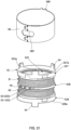
- FIG. 21 illustrates a coil assembly with an electromagnetic shield part detached
- FIG. 22 is an exploded view of the coil assembly.
- coil bobbin part 52 holds coils 61 and 62 wound on the outer circumferential surface the coil bobbin part, surrounds magnet 30 by inner circumferential surface 522a, and guides the movement of movable body 20 including magnet 30.
- Coil bobbin part 52 is a cylindrical body formed from a resin such as a phenolic resin, poly butylene terephthalate (PBT), or the like.
- coil bobbin part 52 is formed from a material containing a phenolic resin such as Bakelite having high flame retardancy.
- coil bobbin part 52 is formed from a material containing a phenolic resin, a higher flame retardancy is obtained, so that it is possible to improve the safety at the time of driving even when heat is generated by Joule heat when a current flows through coils 61 and 62 held by coil bobbin part 52. Moreover, the dimensional accuracy is increased and the positional accuracy of coils 61 and 62 is increased accordingly, so that it is possible to reduce variations in vibration characteristics.
- Coil bobbin part 52 illustrated in FIGS. 2 , 21 , and 22 includes cylindrical bobbin main-body portion 522, middle flange portion 526 and flange portions 527 and 528 protruding from the outer circumference of bobbin main-body portion 522 in the radial direction, terminal tying parts (coil connection parts) 53, movable-range forming parts 54, and linking groove portion 55.
- Coils 61 and 62 are wound around coil bobbin part 52. Coils 61 and 62 are covered by electromagnetic shield part 58. Note that, terminal tying parts (coil connection parts) 53 may also be illustrated and described as terminal tying parts (coil connection parts) 53-1 and 53-2, for convenience.
- Bobbin main-body portion 522 functions as a protective wall portion for protecting coils 61 and 62 against collision by movable body 20 when movable body 20 disposed inside is being driven.
- the thickness of bobbin main-body portion 522 is a thickness that gives such a strength that coils 61 and 62 on the outer circumferential side are not affected at all even when moving movable body 20 makes contact with bobbin main-body portion 522.
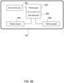
- each of game controller GC and mobile terminal M has communication part 201, processing part 202, drive control part 203, and vibration actuators 204, 205, and/or 206 each of which is vibration actuator 1 as a driving part.
- vibration actuators 204 and 205 are mounted in game controller GC.
- Communication part 201 is connected to an external communication apparatus by wireless communication, and receives a signal from the communication apparatus to output it to processing part 202.
- the external communication apparatus is a game-machine main body as an information communication terminal, and performs communication in accordance with short-range radio communication standards such as Bluetooth (registered trademark) and the like.
- the external communication apparatus is, for example, a base station, and performs communication in accordance with mobile communication standards.
- vibration actuator of the present embodiment in game controller GC or portable terminal M, it is possible to stably obtain excellent vibration characteristics, and it is possible to realize quiet driving.
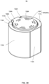
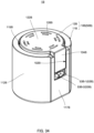
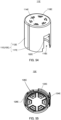
- FIG. 30 is an external perspective view of a vibration actuator according to Embodiment 2 of the present invention
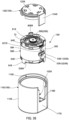
- FIG. 31 is a perspective view of the vibration actuator from which the case is detached.
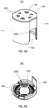
- FIG. 32 is a bottom side perspective view of the case main body
- FIG. 33 is a perspective view of the lid portion as seen from the back side.
- Vibration actuator 1A according to Embodiment 2 differs from vibration actuator 1 only in the outer shape of case 10A, and the other basic configurations are the same. Therefore, in the following description, similar constituent elements are provided with the same names and the same reference numerals with appropriate addition of the letter "A" to the reference numerals.
- Vibration actuator 1A includes driving unit 13A and case 10A for accommodating driving unit 13A which have the same configuration as driving unit 13 of vibration actuator 1.
- driving unit 13A includes coil bobbin part 52A that is configured similarly to coil bobbin part 52, that is covered with electromagnetic shield part 58A, and around which coils are wound.
- movable body 20A having the same configuration as movable body 20 is configured to be suspended via elastic supporting parts ( FIG. 31 illustrates only elastic supporting part 81A). Movable body 20A is joined to elastic supporting part 81A by the sealing part described above without any gap.
- Case 10A is formed in an elliptical cylinder (for example, in an "oval shape") and is composed of case main body 11A and lid portion 12A.
- case 10A is a column having a height (range of motion of movable body 20) allowing movable body 20 to reciprocate in the vibration direction by cooperation between the movable body and coils disposed in case 10, so as to generate a sufficient thrust.
- columnar shapes of cases 10B to 10F described below.
- Case main body 11A as seen in the vibration (axial) direction includes circumferential wall portion 112A including flat surface portions 113A and 117A that are planar outer circumferential surfaces and are disposed symmetrically with respect to the center of opening portion 115A.
- the case main body includes bottom portion 114A.
- Case main body 11A has an elliptical shape, and in the present embodiment, includes flat surface portions 113A and 117A extending parallel to the vibration direction. Flat surface portions 113A and 117A are disposed parallel to each other at the outer circumference of case main body 11A.
- Case main body 11A is formed by circumferential wall portion 112Aand bottom portion 114A in a bottomed cylindrical shape which opens at circular opening portion 115A.
- Flat surface portions 113A and 117A include, for example, outer surfaces parallel to each other, and arc-shaped inner surfaces.
- Case main body 11A includes flat surface portions 113A and 117A, and thus, when attached to the housing, it is easy to mount the case main body on the mounting surface on the housing side on which attachment is to be performed. Also, vibration actuator 1A can cause vibration along the mounting surface. Cutout portion 102A continuous with opening portion 115A is formed in flat surface portion 117A. Cutout portion 102A is formed in a shape that corresponds to and is engageable with hanging portion 124A of lid portion 12A.
- Case main body 11A as seen in the axial direction has an elliptical outer shape, and a circular inner shape.
- Case main body 11A includes therein a space formed in a circular shape which is open at opening portion 115A. This space accommodates cylindrical driving unit 13A.
- a terminal tying part (coil connection part) (not illustrated) is exposed to the outside via cutout portion 102A. When the terminal tying part is disposed on flat surface portion 117A, mounting on an external board becomes easier, and external connection also becomes easy.
- Lid portion 12A and bottom portion 114A form top surface portion 122A and the lower surface portion (bottom portion 114A) of vibration actuator 1, respectively, and are disposed to face movable body 20A of driving unit 13A accommodated in case 10A in the vibration direction of movable body 20A (axial direction) with predetermined gaps being interposed therebetween.
- Lid portion 12A and bottom portion 114A have a function as a movable-range reducing part that serves as a hard stop (movable range limitation) of movable body 20A, and regulate the movable range in which movable body 20A is movable.
- lid portion 12A and bottom portion 114A regulate the movable range of movable body 20A formed by movable-range forming parts 54A of driving unit 13A. That is, lid portion 12A and bottom portion 114A regulate the lengths from lid portion 12A and bottom portion 114A to the edge portions of the upper and lower end portions of driving unit 13A (upper and lower end surfaces (opening end surfaces) of upper and lower flange portions 527A and 528A).
- elastic supporting part 81A makes contact with fixing body 50A (at least one of lid portion 12A and bottom portion 114A) without being plastically deformed, so that elastic supporting part 81Ais not damaged, and reliability can be increased.
- hanging portion 124A is engaged with cutout portion 102A of case main body 11A to close cutout portion 102A.
- Hanging portion 124A is formed such that the outer surface is a flat surface, and the inner surface is in an arc shape whose central axis is oriented in the hanging direction.
- hanging portion 124A is engaged with cutout portion 102A so as to be flush with the outer surface of flat surface portion 117A at the outer surface of the hanging portion.
- the hanging portion accommodates driving unit 13A while positioning the driving unit by the arc surface of the inner surface. Note that, at cutout portion 102A, steps are formed in opening end portion 103A in the vibration direction.
- the steps at opening end portion 103A form recesses that open to the top surface portion 122A side. Since the recesses are formed by a part of case main body 11A and a part of lid portion 12A, the recesses function, for example, as a joint portion for securely joining both of the case main body and the lid portion. An adhesive is applied to the joint portion, or the joint portion is welded. That is, by using the steps at opening end portion 103A, the case main body and the lid portion can be securely joined together by bonding, welding, or the like. Thus, the case main body and the lid portion can be suitably bonded without extrusion of the adhesive from the outer surface of case 10, such as application of the adhesive onto top surface portion 122A.
- Vent holes 126A and 116A having the same function as vent holes 126 and 116 are formed to extend through lid portion 12A and bottom portion 114A, respectively.
- case main body 11A whose outer shape is an elliptical shape (oval shape) when viewed in the vibration (axial) direction, and whose inner shape is circular accommodates driving unit 13Ahaving a circular outer shape.
- the outer-diameter arc center of case main body 11A coincides with the outer-diameter arc center of driving unit 13A and the center of gravity of vibration of movable body 20.
- the outer shape of vibration actuator 1A is an elliptical shape (oval shape) when viewed in the vibration direction (axial direction of the vibration actuator).
- vibration actuator 1A when attaching vibration actuator 1A to the housing, it is possible to easily attach vibration actuator 1A to the housing by bringing flat surface portions 113A and 117A forming a part of the side surface of case main body 11A into contact with a mounting surface (a flat portion) of the housing on which mounting is performed. Thus, it is easier to attach vibration actuator 1A to the housing.
- case 10A includes flat surface portions 113A and 117A parallel to the outer circumferential surface. It is thus possible to secure the stroke length of the vibration along these flat surface portions 113A and 117A.
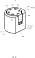
- FIG. 34 is an external perspective view illustrating the vibration actuator according to the third embodiment of the present invention
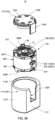
- FIG. 35 is a perspective view illustrating a state in which the case is removed in the same vibration actuator.
- FIG. 36 is a bottom side perspective view of the case main body
- FIG. 37 is a perspective view of the lid portion as seen from the back side.
- Vibration actuator 1B has case 10B and driving unit 13B that have the same functions as those of vibration actuator 1 although having the outer shapes different from case 10 and driving unit 13. Therefore, in the following description, similar constituent elements are provided with the same names and the same reference numerals with appropriate addition of the letter "B" to the reference numerals, and description thereof is omitted as appropriate.
- Vibration actuator 1B includes driving unit 13B and case 10B for accommodating driving unit 13B that is the same as driving unit 13 of vibration actuator 1.
- electromagnetic shield part 58B of driving unit 13B is a cylindrical magnetic material disposed to surround the outer circumferential surface of coil bobbin part 52B around which coils are wound.
- Electromagnetic shield part 58B is formed in a cylindrical shape by engagement between engaging portions 583 and 584 of both end portions of the plate-like magnetic material in the circumferential direction.
- the outer surface of electromagnetic shield part 58B is disposed to be flush with the outer surface of edge portions of the upper and lower end portions of driving unit 13B (upper and lower flange portions 527B and 528B).
- Case 10B includes, in the outer circumferential surface, flat surface portion 117B extending parallel to the vibration direction.
- Case 10B is composed of case main body 11B and lid portion 12B, and has an outer shape of D when viewed in the vibration direction.
- case main body 11B includes arc-shaped circumferential wall portion 112B, flat surface portion 117B disposed as a part of circumferential wall portion 112B and having a flat outer surface, and bottom portion 114B.
- Case main body 11B is formed by circumferential wall portion 112B and bottom portion 114B in a bottomed cylindrical shape which opens at circular opening portion 115B.
- Cutout portion 102B continuous with opening portion 115B is formed in flat surface portion 117B. Cutout portion 102B is formed in a shape that corresponds to and is engageable with hanging portion 124B of lid portion 12B.
- case main body 11B As seen in the axial direction is D-shaped. Case main body 11B includes therein a space defined in a cylindrical shape which is open at opening portion 115B. This space accommodates cylindrical driving unit 13B. Terminal tying parts (coil connection parts) 53B-1 and 53B-2 are exposed to the outside via cutout portion 102B.
- Lid portion 12B and bottom portion 114B form top surface portion 122B and the lower surface portion (bottom portion 114B) of vibration actuator 1, and are disposed to face movable body 20B of driving unit 13B accommodated in case 10B in the vibration direction of movable body 20B with predetermined gaps being interposed therebetween.
- Lid portion 12B and bottom portion 114B have a function as a movable-range reducing part that serves as a hard stop (movable range limitation) of movable body 20B, and regulate the movable range in which movable body 20B is movable.
- lid portion 12B and bottom portion 114B regulate the movable range of movable body 20B formed by movable-range forming parts 54 of driving unit 13B. That is, lid portion 12B and bottom portion 114B regulate the lengths from lid portion 12B and bottom portion 114B to the upper and lower end surfaces (opening end surfaces) of upper and lower flange portions 527B and 528B that are opposite end portions of driving unit 13B separate from each other in the vibration direction.
- elastic supporting part 81B makes contact with fixing body 50B (at least one of lid portion 12B and bottom portion 114B) without being plastically deformed, so that elastic supporting part 81B is not damaged, and reliability can be increased.
- Functions and effects of hanging portion 124B are the same as those of hanging portion 124A, and therefore descriptions thereof are omitted.
- Vent holes 126B and 116B having the same function as vent holes 126 and 116 are formed to extend through lid portion 12B and bottom portion 114B, respectively.
- vibration actuator 1B case main body 11B whose outer shape is a D-shape when viewed in the vibration (axial) direction, and whose inner shape is circular accommodates driving unit 13B having a circular outer shape.
- outer-diameter arc center of case main body 11B coincides with the outer-diameter arc center of driving unit 13B and the center of gravity of vibration of movable body 20.
- the outer shape of vibration actuator 1B as seen in the vibration direction is a shape (e.g., D-shape) having flat surface portion 117B extending parallel to the vibration direction in the outer circumferential surface.
- vibration actuator 1B can cause vibration along the mounting surface.
- terminal tying parts 53B are disposed on flat surface portion 117B.
- vibration actuator 1B it is easier to attach vibration actuator 1B to the housing.
- the outer dimensions of driving unit 13B are the same as those of driving unit 13 of Embodiment 1, the same effects as those of Embodiment 1 can be obtained while maintaining the same vibrational feel as that of Embodiment 1 by using the same lid portion 12B as lid portion 12 and changing only corresponding case main body 11B.
- FIG. 38 is an external perspective view of a vibration actuator according to Embodiment 4 of the present invention
- FIG. 39 is a perspective view of the vibration actuator from which the case is detached.
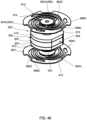
- FIG. 40 is a perspective view of a movable body to which elastic supporting parts are fixed
- FIG. 41 is an exploded perspective view of the movable body and the elastic supporting parts.
- FIG. 42 illustrates a coil assembly with an electromagnetic shield part detached
- FIG. 43 is a bottom-surface-side perspective view of the case main body
- FIG. 44 is a perspective view of the lid portion as seen from the back surface side.
- Vibration actuator 1C has the same functions as those of vibration actuator 1 although case 10C and driving unit 13C have the outer shape different from those of vibration actuator 1. Therefore, in the following description, similar constituent elements are provided with the same names and the same reference numerals with appropriate addition of the letter "C" to the reference numerals, and description thereof is omitted as appropriate.
- vibration actuator 1C includes driving unit 13C and case 10C having the same basic functions as driving unit 13C and case 10 of vibration actuator 1 while having shapes different therefrom.
- Case 10C includes, in the outer circumferential surface, flat surface portion 117C extending parallel to the vibration direction, and further, vibration actuator 1C includes, in the outer circumferential surface, another flat surface portion 113C parallel to flat surface portion 117C.
- Driving unit 13C and case 10C differ from driving unit 13 and case 10 of Embodiment 1 only in their outer shapes, and driving unit 13C has an elliptical outer shape (oval shape) to be accommodated in an elliptical inner area of case 10C having an elliptical shape (oval outer shape).
- Driving unit 13C includes cylindrical coil bobbin part (coil holding part) 52C for holding coils 61C and 62C, movable body 20C, electromagnetic shield part 58C, and elastic supporting parts 81C and 82C.
- Driving unit 13C includes, in the outer circumferential surface, a pair of unit flat surface portions 134 extending in the vibration direction.
- the pair of unit flat surface portions 132 and 134 are formed correspondingly to flat surface portions 113C and 117C of case 10C and are disposed at positions facing flat surface portions 113C and 117C.
- Movable body 20C is supported inside cylindrical coil bobbin part 52C by elastic supporting parts 81C and 82C connected at the upper and lower end portions of the movable body, so as to be capable of reciprocating along coil bobbin part 52C (inner circumferential surface 522a of bobbin main-body portion 522C).
- movable body 20C is supported to be capable of reciprocating in a direction in which lid portion 12C and bottom portion 114C face each other.
- Movable body 20C is joined to elastic supporting parts 81C and 82C by the sealing part without any gap.
- Movable body 20C includes magnet 30C, movable-body cores 41C and 42C, spring retaining parts 22C and 24C, and fixation pins 26C and 28C.
- movable-body cores 41C and 42C and spring retaining parts 22C and 24C are continuously disposed respectively toward opposite sides from magnet 30C in the vibration (axis) direction.
- the outer circumferential surface of magnet 30C and movable-body cores 41C and 42C is disposed inside inner circumferential surface 522a of bobbin main-body portion 522 to face inner circumferential surface 522a with a predetermined gap being interposed between the outer circumferential surface of the magnet and the movable-body cores and the inner circumferential surface of the bobbin main-body portion.
- Movable body 20C has a shape corresponding to the inner shape of case 10C.
- Movable body 20C includes movable-body-side flat portions 20b on the outer circumferential portion, and for example, has the shape of an elliptical plate (or elliptical cylinder) including a pair of parallel movable-body-side flat surface portions 20b.
- Movable-body-side flat surface portions 20b are configured such that outer circumferential flat surface portions 303 formed in the outer circumferential surface of magnet 30C and core flat surface portions 413 and 423 formed in the outer circumferential surfaces of movable-body cores 41C and 42C are positioned to be placed on movable-body-side flat surface portions in the vibration (axis) direction (see FIG. 41 ).
- Elastic supporting parts 81C and 82C include inner circumferential portions 802C, outer circumferential fixing portions 806C, deformation arm portions 804C having the same functions as those of inner circumferential portions 802, deformation arm portions 804, and outer circumferential fixing portions 806 of elastic supporting parts 81 and 82.
- Each of outer circumferential fixing portions 806C includes linear portions 810, and differs from the configuration of outer circumferential fixing portion 806 in that it includes the linear portions.
- Two linear portions 810 are disposed respectively at the outer edges of outer circumferential fixing portions 806C such that the linear portions are parallel to each other across the center of the axis, and the linear portions can be disposed on the same planes as movable-body-side flat surface portions 20b of movable body 20C, respectively.
- Positioning groove 808C having a cutout shape is formed in one portion of the outer edges having linear portions 810.
- coil bobbin part 52C The basic configuration of coil bobbin part (coil holding part) 52C is the same as coil bobbin part 52. As illustrated in FIG. 42 , coil bobbin part 52C holds coils 61C and 62C wound on the outer circumferential surface the coil bobbin part, surrounds magnet 30C by inner circumferential surface 522a, and guides the movement of movable body 20C including magnet 30C.
- Coil bobbin part 52C includes cylindrical bobbin main-body portion 522C, middle flange portion 526C and flange portions 527C and 528C protruding from the outer circumference of bobbin main-body portion 522C in the radial direction, terminal tying parts (coil connection parts) 53C, movable-range forming parts 54C, and linking groove portion 55C.
- coil bobbin part 52C the outer circumference of bobbin main-body portion 522C is provided with coil attachment portions 5201C and 5202C between middle flange portion 526C and flange portions 527C and 528C.
- a pair of coils 61C and 62C are disposed to be wound around coil attachment portions 5201C and 5202C.
- Coils 61C and 62C are covered by electromagnetic shield part 58C.
- Terminal tying parts (coil connection parts) 53C-1 and 53C-2 are disposed to protrude from a flat portion of middle flange portion 526C.
- the inner circumferential surface of coil bobbin part 52C that is, inner circumferential surface 522a of bobbin main-body portion 522C includes inner circumferential flat surface portions 5222.
- Inner circumferential flat surface portions 5222 are disposed to correspondingly face movable-body-side flat surface portions 20b of movable body 20C. Note that, inner circumferential flat surface portions 5222 and movable-body-side flat surface portions 20b are disposed at positions corresponding to flat surface portions 113C and 117C of case 10C.
- Movable-body-side flat surface portions 20b (outer circumferential flat surface portions 303) are narrower in a direction perpendicular to the vibration direction than inner circumferential flat surface portions 5222. Therefore, movable-body-side flat surface portions 20b including outer circumferential flat surface portions 303 and inner circumferential flat surface portions 5222, can be disposed close to each other, and thus, further miniaturization and thickness reduction of vibration actuator 1C can be achieved.
- Case 10C is configured in an elliptical cylindrical shape by case main body 11C and lid portion 12C, and accommodates driving unit 13C.
- case main body 11C includes circumferential wall portion 112C having flat surface portions 113C and 117C disposed symmetrically with respect to the center of the circle in the circumference, and bottom portion 114C.
- case main body 11C is formed in a bottomed cylindrical shape which opens at elliptical opening portion 115C.
- Flat surface portions 113C and 117C respectively include outer surfaces and inner surfaces parallel with each other. Cutout portion 102C continuous with opening portion 115C is formed in flat surface portion 117C. Cutout portion 102C is formed in a shape that corresponds to and is engageable with hanging portion 124C of lid portion 12C.
- Case main body 11C as seen in the axial direction has an elliptical shape including flat surface portions 113C and 117C to each other in the outer circumferential surface, and includes an inner space of an elliptical shape (oval shape) which is open at opening portion 115C.
- This space accommodates driving unit 13C including elliptical unit flat surface portions 132 and 134 as seen in the vibration direction.
- Terminal tying parts (coil connection parts) 53C-1 and 53C-2 are exposed to the outside through cutout portion 102C.
- lid portion 12C and bottom portion 114C form top surface portion 122C and the lower surface portion (bottom portion 114C) of vibration actuator 1.
- lid portion 12C and bottom portion 114C have a function as a movable-range reducing part that serves as a hard stop (movable range limitation) of movable body 20C, and regulate the movable range in which movable body 20C is movable.
- Lid portion 12C and bottom portion 114C regulate, as the movable range, the length to the edge portions of the upper and lower end portions of driving unit 13C (the upper and lower end surfaces (opening end surfaces) of upper and lower flange portions 527C and 528C).
- hanging portion 124C is engaged with cutout portion 102C of case main body 11C to close cutout portion 102C.
- Hanging portion 124C is formed such that the outer surface is a flat surface, and the inner surface is in an arc shape whose central axis is oriented in the hanging direction. Accordingly, hanging portion 124C is engaged with cutout portion 102C.
- the outer surface of the hanging portion is flush with the outer surface of flat surface portion 117C.
- the arc surface of the inner surface of the hanging portion serves as an arc surface continuous with the inner surface of flat surface portion 117C.
- Driving unit 13C is thus positioned and accommodated.
- Vent holes 126C and 116C having the same function as vent holes 126 and 116 are formed to extend through lid portion 12C and bottom portion 114C, respectively.
- vibration actuator 1C elliptical driving unit 13C having an outer shape corresponding to the inner shape of case main body 11C is accommodated in elliptical bottomed cylindrical case main body 11C whose outer shape and inner shape are elliptical when viewed in the vibration (axial) direction.
- the outer-diameter arc center of case main body 11C coincides with the outer-diameter arc center of driving unit 13C and the center of gravity of vibration of movable body 20C.
- vibration actuator 1C is an elliptical shape (e.g., "oval shape") when viewed in the vibration direction (axial direction of the vibration actuator).
- vibration actuator 1C when attaching vibration actuator 1C to the housing, it is possible to attach vibration actuator 1C to the housing by bringing flat surface portions 113C and 117C forming a part of the side surface of case main body 11C into contact with a flat surface portion of the housing on which mounting is performed. Thus, it is easier to attach vibration actuator 1C to the housing.
- case main body 11C can have the same outermost diameter as the outer diameter of a circular case main body with the same outer diameter (case main body 11 of Embodiment 1). It is thus possible to reduce the size of the vibration actuator.
- case 10C includes flat surface portions 113C and 117C parallel to the outer circumferential surface. It is thus possible to secure the stroke length of the vibration along these flat surface portions 113C and 117C.
- FIG. 45 is an external perspective view of a vibration actuator according to Embodiment 5 of the present invention
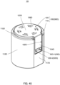
- FIG. 46 is a perspective view of the vibration actuator from which the case is detached.
- FIG. 47 is a perspective view of a movable body to which elastic supporting parts are fixed
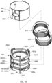
- FIG. 48 is an exploded perspective view of the movable body and the elastic supporting parts.
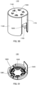
- FIG. 49 illustrates a coil assembly with an electromagnetic shield part detached
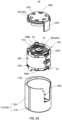
- FIG. 50 is a bottom-surface-side perspective view of the case main body
- FIG. 51 is a perspective view of the lid portion as seen from the back surface side.
- Vibration actuator 1D has the same functions as those of vibration actuator 1 although case 10D and driving unit 13D have the outer shape different from those of vibration actuator 1. Therefore, in the following description, similar constituent elements are provided with the same names and the same reference numerals with appropriate addition of the letter "D" to the reference numerals, and description thereof is omitted as appropriate.
- vibration actuator 1D includes driving unit 13D and case 10D having the same basic functions as driving unit 13 and case 10 of vibration actuator 1 while having shapes different therefrom.
- Case 10D differs from case 10 in that the outer circumferential surface has flat surface portion 117D extending parallel to the vibration direction. Further, driving unit 13D can be accommodated in case 10D and has a shape corresponding to the shape of case 10D.
- Driving unit 13D includes electromagnetic shield part 58D, coils 61D and 62D, coil bobbin part 52D, movable body 20D, electromagnetic shield part 58D, and elastic supporting parts 81D and 82D.
- driving unit 13D includes, in the outer circumferential surface, unit flat surface portion 134 extending in the vibration direction.
- the outer shape of driving unit 13D with this configuration has a D-shape.
- Unit flat surface portion 134 is provided in the outer shape of coil bobbin part 52D and electromagnetic shield part 58D.
- Terminal tying parts 53C-1 and 53C-2 are disposed in unit flat surface portion 134.
- Movable body 20D is supported inside cylindrical coil bobbin part 52D by elastic supporting parts 81D and 82D connected at the upper and lower end portions of the movable body, so as to be capable of reciprocating along coil bobbin part 52D (inner circumferential surface 522a of bobbin main-body portion 522D).
- movable body 20D is supported to be capable of reciprocating in a direction in which lid portion 12D and bottom portion 114D face each other.
- Movable body 20D is joined to elastic supporting parts 81D and 82D by the sealing part without any gap.
- Movable body 20D includes magnet 30D, movable-body cores 41D and 42D, spring retaining parts 22D and 24D, and fixation pins 26D and 28D.
- movable-body cores 41D and 42D and spring retaining parts 22D and 24D are continuously disposed respectively toward opposite sides from magnet 30D in the vibration (axis) direction.
- the outer circumferential surface of magnet 30D and movable-body cores 41D and 42D as a movable-body-side outer circumferential surface is disposed inside inner circumferential surface 522a of bobbin main-body portion 522D to face inner circumferential surface 522a with a predetermined gap being interposed between the outer circumferential surface of the magnet and the movable-body cores and the inner circumferential surface of the bobbin main-body portion.
- Movable body 20D has a shape corresponding to the inner shape of case 10D.
- Movable body 20D includes one movable-body-side flat surface portion 20b on the outer circumferential portion (including outer circumferential flat surface portion 303 of the magnet), and for example, has the shape of a D-shaped plate (or D-shaped column) when viewed in the vibration direction.
- Such a shape includes movable-body-side flat surface portion 20b.
- Movable-body-side flat surface portion 20b is formed by outer circumferential flat surface portion 303 and core flat surface portions 413 and 423 formed respectively on parts of the outer circumferential surfaces of magnet 30D and movable-body cores 41D and 42D (see FIG. 48 ). Outer circumferential flat surface portion 303 and core flat surface portions 413 and 423 are positioned to be placed on top of the other in the vibration (axis) direction.
- Elastic supporting parts 81D and 82D include inner circumferential portions 802D, outer circumferential fixing portions 806D, deformation arm portions 804D having the same functions as those of inner circumferential portions 802, deformation arm portions 804, and outer circumferential fixing portions 806 of elastic supporting parts 81 and 82 in Embodiment 1.
- Each of outer circumferential fixing portions 806D includes linear portions 810, and differs from the configuration of outer circumferential fixing portion 806 in that it includes the linear portions.
- Two linear portions 810 are disposed at a part of the outer edges of each of outer circumferential fixing portions 806D, and can be disposed on the same planes as movable-body-side flat surface portions 20b of movable body 20D.
- Positioning groove 808D having a cutout shape is formed in one portion of the outer edges having linear portions 810.
- coil bobbin part (coil holding part) 52D The basic configuration of coil bobbin part (coil holding part) 52D is the same as coil bobbin part 52. As illustrated in FIG. 49 , coil bobbin part 52D holds coils 61D and 62D wound on the outer circumferential surface the coil bobbin part, surrounds magnet 30D (see FIG. 48 ) by inner circumferential surface 522a, and guides the movement of movable body 20D including magnet 30D.
- Coil bobbin part 52D includes cylindrical bobbin main-body portion 522D, middle flange portion 526D and flange portions 527D and 528D protruding from the outer circumference of bobbin main-body portion 522D in the radial direction, terminal tying parts (coil connection parts) 53D-1 and 53-2, movable-range forming parts 54D, and linking groove portion 55D.
- coil bobbin part 52D the outer circumference of bobbin main-body portion 522D is provided with coil attachment portions 5201D and 5202D between middle flange portion 526D and flange portions 527D and 528D.
- a pair of coils 61 and 62 are disposed to be wound around coil attachment portions 5201D and 5202D.
- Coils 61D and 62D are covered by electromagnetic shield part 58D.
- Terminal tying parts (coil connection parts) 53D-1 and 53D-2 are disposed to protrude from a flat portion of middle flange portion 526D.
- Coil bobbin part 52D includes flat surface portion 5224 extending parallel to the vibration direction.
- the inner circumferential surface of flat surface portion 5224 that is, a part of inner circumferential surface 522a of bobbin main-body portion 522D is an inner circumferential flat surface portion.
- the inner circumferential flat surface portion of flat surface portion 5224 is disposed to correspondingly face movable-body-side flat surface portion 20b of movable body 20D. These surface portions are disposed close to each other.
- flat surface portion 5224 and movable-body-side flat surface portions 20b are disposed at a position corresponding to flat surface portion 117D of case 10D.
- Case 10D includes case main body 11D and lid portion 12D and is formed in a columnar shape having a D shape as seen in the vibration direction. Case 10D accommodates driving unit 13D. Specifically, case main body 11D includes circumferential wall portion 112D partly provided with flat surface portion 117D, and bottom portion 114D. Case main body 11D is formed by circumferential wall portion 112D and bottom portion 114D in a bottomed cylindrical shape which opens at D-shaped opening portion 115D.
- Flat surface portion 117D has a flat outer surface. Cutout portion 102D that extends through the outer surface and the inner surface and is continuous to opening portion 115D is formed in flat surface portion 117D. Cutout portion 102D is formed in a shape that corresponds to and is engageable with hanging portion 124D of lid portion 12D.
- case main body 11D as seen in the axial direction is a D shape
- the inner shape (the shape of inner circumferential surface as seen in the vibration direction) is also a D shape corresponding to the outer shape.
- Case main body 11D includes a space formed in a D shape that is open at opening portion 115D.
- Cylindrical driving unit 13D including movable-body-side flat surface portions 20b in the outer circumferential surface is accommodated in this space.
- Terminal tying parts (coil connection parts) 53D-1 and 53D-2 are exposed to the outside through cutout portion 102D.
- lid portion 12D and bottom portion 114D form top surface portion 122D and bottom portion 114D of vibration actuator 1.
- lid portion 12D and bottom portion 114D have a function as a movable-range reducing part that serves as a hard stop (movable range limitation) of movable body 20D.
- Lid portion 12D and bottom portion 114D regulate, as the movable range, the length to the edge portions of the upper and lower end portions of driving unit 13D (the upper and lower end surfaces (opening end surfaces) of upper and lower flange portions 527D and 528D).
- the movable body 20D even when a force causing movable body 20D to move beyond the movable range is applied to the movable body, it is possible to increase the reliability without any damage being caused to elastic supporting parts 81D and 82D.
- hanging portion 124D is engaged with cutout portion 102D of case main body 11D to close cutout portion 102D.
- Hanging portion 124D is formed such that the outer surface is a flat surface, and the inner surface is in an arc shape whose central axis is oriented in the hanging direction. Accordingly, hanging portion 124D is engaged with cutout portion 102D.
- the outer surface of the hanging portion is flush with the outer surface of flat surface portion 117D.
- the arc surface of the inner surface of the hanging portion serves as an arc surface continuous with the inner surface of flat surface portion 117D.
- Driving unit 13D is thus positioned and accommodated.
- Vent holes 126D and 116D having the same function as vent holes 126 and 116 are formed to extent through lid portion 12D and bottom portion 114D, respectively.
- D-shaped driving unit 13D having an outer shape corresponding to the inner shape of case main body 11D is accommodated in D-shaped bottomed cylindrical case main body 11D whose outer shape and inner shape are D-shaped when viewed in the vibration (axial) direction.
- the outer-diameter arc center of case main body 11D coincides with the outer-diameter arc center of driving unit 13D and the center of gravity of vibration of movable body 20D.
- the outer shape of vibration actuator 1D as seen in the vibration direction (axial direction of the vibration actuator is a shape (D shape) including flat surface portion 117D in the outer circumferential surface.
- flat surface portion 117D of case main body 11D forming the outer circumferential surface can make contact with a flat surface portion of a housing where the case main body is mounted.
- the flat surfaces can be joined. It is thus possible to attach vibration actuator 1D to the housing.
- case main body 11D can have an outermost diameter as the outer diameter of a circular case main body with the same outer diameter (case main body 11 of Embodiment 1). It is thus possible to reduce the size of the vibration actuator.
- FIG. 52 is an external perspective view of a vibration actuator according to Embodiment 6 of the present invention
- FIG. 53 is a perspective view of the vibration actuator from which the case is detached
- FIG. 54 is a bottom-surface-side perspective view of the case main body.
- FIG. 55 is a perspective view of the lid portion from the back surface side
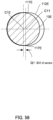
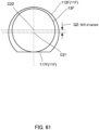
- FIG. 56 is a diagram schematically illustrating the positional relationship between the driving unit and the case in the vibration actuator according to Embodiment 6.
- Vibration actuator 1E is similar in basic configuration to vibration actuator 1A of Embodiment 2, but differs from vibration actuator 1A in the width of flat surface portion 117E and the positional relation between driving unit 13E and case 10E.
- vibration actuator 1E differs from vibration actuator 1A in that the center of driving unit 13E and the center of movable body 20E as seen in the vibration direction (axial direction) are disposed at positions eccentric with respect to the center of case 10E.
- vibration actuator 1E differs from vibration actuator 1A in that the outer arc center of driving unit 13E and the center of gravity of vibration of movable body 20E are shifted in a direction perpendicular to the vibration direction with respect to the center of the arc portion of the outer shape of case 10E.
- similar components are denoted by the same names and the reference symbols in which the letter "A" is changed to "E," and description thereof will be omitted as appropriate.
- Vibration actuator 1E includes driving unit 13E and case 10E for accommodating driving unit 13E which have the same configuration as driving unit 13.
- Case 10E is formed in an elliptical cylindrical shape (oval shape) including, in the outer circumferential surface, flat surface portion 117E extending in the vibration direction. Case 10E includes case main body 11E and lid portion 12E.
- case main body 11E The outer circumferential surface of case main body 11E as seen in the vibration (axial) direction is a flat surface.
- the case main body includes circumferential wall portion 112E including a pair of flat surface portions 117E disposed to face each other.
- the case main body also includes bottom portion 114E.
- Case main body 11E is formed by circumferential wall portion 112E and bottom portion 114E in a bottomed cylindrical shape which opens at elliptical (oval) opening portion 115E.
- Flat surface portions 117E are, for example, portions of circumferential wall portion 112E including outer surfaces and inner surfaces parallel with each other.
- cutout portion 102E that continues to opening portion 115E is formed at a portion of the case main body on a side on which the center of accommodated driving unit 13E (coil bobbin part 52E) is eccentric with respect to the center of the case main body as seen in the vibration direction.
- Cutout portion 102E is formed in a shape that corresponds to and is engageable with hanging portion 124E of lid portion 12E.
- Case main body 11E includes an inner space which is open at elliptical opening portion 115E. This inner space accommodates cylindrical driving unit 13E. Terminal tying parts (coil connection parts) 53E-1 and 53E-2 are exposed to the outside via cutout portion 102E.
- elastic supporting part 81E makes contact with fixing body 50E (at least one of lid portion 12E and bottom portion 114E) without being plastically deformed, so that elastic supporting part 81E is not damaged, and reliability can be increased.
Landscapes
- Engineering & Computer Science (AREA)
- Mechanical Engineering (AREA)
- Physics & Mathematics (AREA)
- Electromagnetism (AREA)
- Power Engineering (AREA)
- Reciprocating, Oscillating Or Vibrating Motors (AREA)
- Apparatuses For Generation Of Mechanical Vibrations (AREA)
Claims (12)
- Actionneur de vibration, comprenant :un corps mobile (20) qui comporte en son centre un aimant (30) ayant une forme en colonne et dans lequel des parties de maintien de ressort (22, 24) sont disposées respectivement sur les surfaces avant et arrière de l'aimant dans une direction axiale de l'aimant (30) ;un corps de fixation (50) pour accueillir le corps mobile (20), le corps de fixation (50) ayant une forme cylindrique et comportant une paire de bobines annulaires (61, 62) disposées radialement à l'extérieur du corps mobile (20) ;une paire de parties élastiques de support (81, 82) pour soutenir le corps mobile (20) de manière à ce que le corps mobile (20) soit capable d'effectuer des vibrations de va-et-vient dans une direction de vibration le long de la direction axiale, chacune des parties élastiques de support (81, 82) étant reliée au corps de fixation (50) au niveau d'une section circonférentielle extérieure (806) et étant reliée à une partie correspondante des parties de maintien de ressort (22, 24) au niveau d'une section circonférentielle intérieure (802) ;caractérisé en ce que l'actionneur de vibration comprend en outreune partie de scellement (90) qui est disposée au niveau d'une section de joint entre la section circonférentielle intérieure (802) et le corps mobile (20) et qui scelle la section de joint, dans laquelleles parties de maintien de ressort (22, 24) comportent des sections formant un évidement (25) continues avec une surface de jonction (224a, 244a) avec les sections circonférentielles intérieures (802),la section circonférentielle intérieure (802) présente une section en retrait (809) qui est découpée sur une circonférence extérieure de la section circonférentielle intérieure (802) dans la direction circonférentielle et située sur la surface de jonction (224a, 244), etla partie de scellement (90) est capable de connecter et sceller la section en retrait (809) et la section formant un évidement (25) en communication l'une avec l'autre, et elle scelle la section de joint.
- Actionneur de vibration selon la revendication 1, dans lequel :la section circonférentielle intérieure (802) est reliée à une circonférence extérieure d'au moins une section d'extrémité des sections d'extrémité opposées du corps mobile (20) séparées l'une de l'autre dans la direction de vibration, etla partie de scellement (90) est disposée pour couvrir extérieurement une section de joint entre la section circonférentielle intérieure (802) et ladite au moins une section d'extrémité sans aucun espace.
- Actionneur de vibration selon la revendication 1 ou 2, dans lequel
la partie de scellement (90) est formée d'un adhésif ayant au moins l'une parmi une propriété thermodurcissable, une propriété de durcissement aux UV, et anaérobie, et elle scelle un espace au niveau de la section de joint. - Actionneur de vibration selon l'une quelconque des revendications 1 à 3, dans lequel :la section circonférentielle intérieure (802) est continue jusqu'à une limite de la section de joint lorsqu'elle est reliée au corps mobile (20),
etla partie de scellement (90) ferme et scelle la section en retrait et la limite de la section de joint. - Actionneur de vibration selon l'une quelconque des revendications 1 à 4, dans lequel :le corps de fixation (50) comporte une partie cylindrique de maintien de la bobine (52) pour maintenir la bobine (61, 62), et un boîtier (10A) pour accueillir la partie cylindrique de maintien de la bobine (52), etle boîtier (10A) comporte, sur une surface circonférentielle extérieure, une section de surface plane (113A, 117A) s'étendant parallèlement à la direction de vibration.
- Actionneur de vibration selon la revendication 5, dans lequel
une partie de connexion à la bobine (52) est disposée au niveau de la section de surface plane (117A). - Actionneur de vibration selon la revendication 5 ou 6, dans lequel
le boîtier (10) comporte, dans la surface circonférentielle extérieure, une autre section de surface plane (117A) s'étendant parallèlement à la section de surface plane. - Actionneur de vibration selon l'une quelconque des revendications 5 à 7, dans lequel :à une position correspondant à la section de surface plane, une surface circonférentielle intérieure de la partie cylindrique de maintien de la bobine et une surface circonférentielle extérieure de l'aimant comportent respectivement une section de surface plane circonférentielle intérieure (5222) et une section de surface plane circonférentielle extérieure (303) faisant face l'une à l'autre, etla section de surface plane circonférentielle extérieure (303) est plus étroite que la section de surface plane circonférentielle intérieure (5222) dans une direction perpendiculaire à la direction de vibration.
- Actionneur de vibration selon l'une quelconque des revendications 5 à 8, dans lequel :une forme extérieure de la partie cylindrique de maintien de la bobine (52e) telle qu'observée dans la direction de vibration est circulaire, etla partie cylindrique de maintien de la bobine (52E) telle qu'observée dans la direction de vibration est disposée de manière excentrique par rapport à un centre de forme extérieure du boîtier (10E) ou un centre d'arc du diamètre extérieur du boîtier (10E).
- Actionneur de vibration selon la revendication 9, dans lequel
une partie de connexion à la bobine (53) est disposée sur un côté de la forme extérieure du boîtier, le côté de la forme extérieure étant sur un côté où se trouve un centre de la partie cylindrique de maintien de la bobine par rapport au centre de forme extérieure du boîtier de la partie cylindrique de maintien de la bobine (52). - Actionneur de vibration selon la revendication 9, dans lequel
une partie de connexion à la bobine (53) est disposée sur le côté de la section de surface plane formée dans la surface circonférentielle extérieure du boîtier de la partie cylindrique de maintien de la bobine (52). - Dispositif électronique dans lequel
un actionneur de vibration selon l'une quelconque des revendications 1 à 11 est monté.
Applications Claiming Priority (2)
| Application Number | Priority Date | Filing Date | Title |
|---|---|---|---|
| JP2020032251 | 2020-02-27 | ||
| PCT/JP2021/007585 WO2021172577A1 (fr) | 2020-02-27 | 2021-02-26 | Actionneur de vibration et dispositif électronique |
Publications (3)
| Publication Number | Publication Date |
|---|---|
| EP4112191A1 EP4112191A1 (fr) | 2023-01-04 |
| EP4112191A4 EP4112191A4 (fr) | 2024-03-06 |
| EP4112191B1 true EP4112191B1 (fr) | 2025-04-02 |
Family
ID=77491657
Family Applications (1)
| Application Number | Title | Priority Date | Filing Date |
|---|---|---|---|
| EP21761712.5A Active EP4112191B1 (fr) | 2020-02-27 | 2021-02-26 | Actionneur de vibration et dispositif électronique |
Country Status (5)
| Country | Link |
|---|---|
| US (1) | US12337346B2 (fr) |
| EP (1) | EP4112191B1 (fr) |
| JP (1) | JP7658530B2 (fr) |
| CN (1) | CN115175773B (fr) |
| WO (1) | WO2021172577A1 (fr) |
Families Citing this family (10)
| Publication number | Priority date | Publication date | Assignee | Title |
|---|---|---|---|---|
| JP7850137B2 (ja) * | 2021-03-30 | 2026-04-22 | フォスター電機株式会社 | 振動アクチュエータ |
| GB2607085B (en) * | 2021-05-27 | 2023-11-08 | Groundwaves Ltd | A transducer for producing vibrational movement |
| JP2023006567A (ja) * | 2021-06-30 | 2023-01-18 | ミネベアミツミ株式会社 | 振動装置 |
| JP7726518B2 (ja) * | 2021-08-06 | 2025-08-20 | ミネベアミツミ株式会社 | 振動アクチュエーター |
| JP2023176492A (ja) * | 2022-05-31 | 2023-12-13 | ミネベアミツミ株式会社 | 振動アクチュエータ及び電子機器 |
| CN115051525B (zh) * | 2022-06-30 | 2025-04-04 | 瑞声光电科技(常州)有限公司 | 线性振动马达 |
| JP7652804B2 (ja) * | 2022-09-09 | 2025-03-27 | エーエーシー マイクロテック(チャンヂョウ)カンパニー リミテッド | 振動モータ |
| WO2024226586A2 (fr) * | 2023-04-24 | 2024-10-31 | Apollo Neuroscience, Inc. | Actionneur vibrant destiné à être utilisé avec des dispositifs électroniques portables |
| CN221305610U (zh) * | 2023-11-03 | 2024-07-09 | 湖北省钻马智控科技有限公司 | 一种振动马达 |
| CN119231867B (zh) * | 2024-11-28 | 2025-03-14 | 克瑞科技(东莞)有限公司 | 一种小家电用的直线电机 |
Family Cites Families (11)
| Publication number | Priority date | Publication date | Assignee | Title |
|---|---|---|---|---|
| JPH09117721A (ja) * | 1994-09-28 | 1997-05-06 | Seiko Instr Inc | 振動モジュール |
| JP3748637B2 (ja) | 1996-10-14 | 2006-02-22 | 松下電器産業株式会社 | 携帯機器用振動発生装置 |
| JP2010069356A (ja) * | 2008-09-16 | 2010-04-02 | Sanyo Electric Co Ltd | 往復振動器 |
| JP5659426B2 (ja) * | 2010-02-16 | 2015-01-28 | 日本電産セイミツ株式会社 | 振動発生装置 |
| KR101598584B1 (ko) * | 2013-12-30 | 2016-03-02 | 주식회사 엠플러스 | 진동발생장치 |
| EP3725349B1 (fr) | 2014-10-20 | 2024-04-10 | Becton, Dickinson and Company | Systèmes améliorés pour l'administration de médicaments |
| JP2017099153A (ja) * | 2015-11-25 | 2017-06-01 | 日本電産セイミツ株式会社 | 振動モータ、無音報知デバイスおよび振動モータの製造方法 |
| JP2018143041A (ja) * | 2017-02-28 | 2018-09-13 | 日本電産セイミツ株式会社 | 振動モータ |
| JP2019115187A (ja) * | 2017-12-25 | 2019-07-11 | フォスター電機株式会社 | 振動アクチュエータ |
| CN208955873U (zh) * | 2018-08-03 | 2019-06-07 | 瑞声科技(南京)有限公司 | 振动电机 |
| CN209860768U (zh) * | 2019-06-27 | 2019-12-27 | 潍坊歌尔电子有限公司 | 一种垂直线性振动马达及电子产品 |
-
2021
- 2021-02-26 US US17/802,548 patent/US12337346B2/en active Active
- 2021-02-26 CN CN202180017165.8A patent/CN115175773B/zh active Active
- 2021-02-26 EP EP21761712.5A patent/EP4112191B1/fr active Active
- 2021-02-26 JP JP2022503379A patent/JP7658530B2/ja active Active
- 2021-02-26 WO PCT/JP2021/007585 patent/WO2021172577A1/fr not_active Ceased
Also Published As
| Publication number | Publication date |
|---|---|
| JP7658530B2 (ja) | 2025-04-08 |
| CN115175773B (zh) | 2026-02-13 |
| CN115175773A (zh) | 2022-10-11 |
| US20230101894A1 (en) | 2023-03-30 |
| EP4112191A1 (fr) | 2023-01-04 |
| US12337346B2 (en) | 2025-06-24 |
| EP4112191A4 (fr) | 2024-03-06 |
| JPWO2021172577A1 (fr) | 2021-09-02 |
| WO2021172577A1 (fr) | 2021-09-02 |
Similar Documents
| Publication | Publication Date | Title |
|---|---|---|
| EP4112191B1 (fr) | Actionneur de vibration et dispositif électronique | |
| CN114337179B (zh) | 振动致动器及电子设备 | |
| US20240213867A1 (en) | Vibration actuator and electronic device | |
| EP4112192A1 (fr) | Actionneur de vibration et dispositif électronique | |
| JP7827258B2 (ja) | 振動アクチュエータ及び電気機器 | |
| US12424916B2 (en) | Vibration actuator with movable body and fixing body with gap and fluid and pipe resistance to fluid | |
| US20250125701A1 (en) | Vibration actuator | |
| CN115549429A (zh) | 振动促动器以及电气设备 | |
| US20250332612A1 (en) | Vibration actuator and electronic apparatus |
Legal Events
| Date | Code | Title | Description |
|---|---|---|---|
| STAA | Information on the status of an ep patent application or granted ep patent |
Free format text: STATUS: THE INTERNATIONAL PUBLICATION HAS BEEN MADE |
|
| PUAI | Public reference made under article 153(3) epc to a published international application that has entered the european phase |
Free format text: ORIGINAL CODE: 0009012 |
|
| STAA | Information on the status of an ep patent application or granted ep patent |
Free format text: STATUS: REQUEST FOR EXAMINATION WAS MADE |
|
| 17P | Request for examination filed |
Effective date: 20220826 |
|
| AK | Designated contracting states |
Kind code of ref document: A1 Designated state(s): AL AT BE BG CH CY CZ DE DK EE ES FI FR GB GR HR HU IE IS IT LI LT LU LV MC MK MT NL NO PL PT RO RS SE SI SK SM TR |
|
| DAV | Request for validation of the european patent (deleted) | ||
| DAX | Request for extension of the european patent (deleted) | ||
| A4 | Supplementary search report drawn up and despatched |
Effective date: 20240205 |
|
| RIC1 | Information provided on ipc code assigned before grant |
Ipc: H02K 33/16 20060101ALI20240130BHEP Ipc: H02K 33/00 20060101ALI20240130BHEP Ipc: B06B 1/14 20060101ALI20240130BHEP Ipc: B06B 1/04 20060101AFI20240130BHEP |
|
| GRAP | Despatch of communication of intention to grant a patent |
Free format text: ORIGINAL CODE: EPIDOSNIGR1 |
|
| STAA | Information on the status of an ep patent application or granted ep patent |
Free format text: STATUS: GRANT OF PATENT IS INTENDED |
|
| INTG | Intention to grant announced |
Effective date: 20241014 |
|
| GRAS | Grant fee paid |
Free format text: ORIGINAL CODE: EPIDOSNIGR3 |
|
| GRAA | (expected) grant |
Free format text: ORIGINAL CODE: 0009210 |
|
| STAA | Information on the status of an ep patent application or granted ep patent |
Free format text: STATUS: THE PATENT HAS BEEN GRANTED |
|
| AK | Designated contracting states |
Kind code of ref document: B1 Designated state(s): AL AT BE BG CH CY CZ DE DK EE ES FI FR GB GR HR HU IE IS IT LI LT LU LV MC MK MT NL NO PL PT RO RS SE SI SK SM TR |
|
| REG | Reference to a national code |
Ref country code: GB Ref legal event code: FG4D |
|
| REG | Reference to a national code |
Ref country code: CH Ref legal event code: EP |
|
| REG | Reference to a national code |
Ref country code: DE Ref legal event code: R096 Ref document number: 602021028587 Country of ref document: DE |
|
| REG | Reference to a national code |
Ref country code: IE Ref legal event code: FG4D |
|
| P01 | Opt-out of the competence of the unified patent court (upc) registered |
Free format text: CASE NUMBER: APP_16230/2025 Effective date: 20250403 |
|
| REG | Reference to a national code |
Ref country code: NL Ref legal event code: MP Effective date: 20250402 |
|
| PG25 | Lapsed in a contracting state [announced via postgrant information from national office to epo] |
Ref country code: NL Free format text: LAPSE BECAUSE OF FAILURE TO SUBMIT A TRANSLATION OF THE DESCRIPTION OR TO PAY THE FEE WITHIN THE PRESCRIBED TIME-LIMIT Effective date: 20250402 |
|
| REG | Reference to a national code |
Ref country code: AT Ref legal event code: MK05 Ref document number: 1780788 Country of ref document: AT Kind code of ref document: T Effective date: 20250402 |
|
| PG25 | Lapsed in a contracting state [announced via postgrant information from national office to epo] |
Ref country code: FI Free format text: LAPSE BECAUSE OF FAILURE TO SUBMIT A TRANSLATION OF THE DESCRIPTION OR TO PAY THE FEE WITHIN THE PRESCRIBED TIME-LIMIT Effective date: 20250402 Ref country code: PT Free format text: LAPSE BECAUSE OF FAILURE TO SUBMIT A TRANSLATION OF THE DESCRIPTION OR TO PAY THE FEE WITHIN THE PRESCRIBED TIME-LIMIT Effective date: 20250804 Ref country code: ES Free format text: LAPSE BECAUSE OF FAILURE TO SUBMIT A TRANSLATION OF THE DESCRIPTION OR TO PAY THE FEE WITHIN THE PRESCRIBED TIME-LIMIT Effective date: 20250402 |
|
| REG | Reference to a national code |
Ref country code: LT Ref legal event code: MG9D |
|
| PG25 | Lapsed in a contracting state [announced via postgrant information from national office to epo] |
Ref country code: GR Free format text: LAPSE BECAUSE OF FAILURE TO SUBMIT A TRANSLATION OF THE DESCRIPTION OR TO PAY THE FEE WITHIN THE PRESCRIBED TIME-LIMIT Effective date: 20250703 Ref country code: NO Free format text: LAPSE BECAUSE OF FAILURE TO SUBMIT A TRANSLATION OF THE DESCRIPTION OR TO PAY THE FEE WITHIN THE PRESCRIBED TIME-LIMIT Effective date: 20250702 |
|
| PG25 | Lapsed in a contracting state [announced via postgrant information from national office to epo] |
Ref country code: PL Free format text: LAPSE BECAUSE OF FAILURE TO SUBMIT A TRANSLATION OF THE DESCRIPTION OR TO PAY THE FEE WITHIN THE PRESCRIBED TIME-LIMIT Effective date: 20250402 |
|
| PG25 | Lapsed in a contracting state [announced via postgrant information from national office to epo] |
Ref country code: BG Free format text: LAPSE BECAUSE OF FAILURE TO SUBMIT A TRANSLATION OF THE DESCRIPTION OR TO PAY THE FEE WITHIN THE PRESCRIBED TIME-LIMIT Effective date: 20250402 |
|
| PG25 | Lapsed in a contracting state [announced via postgrant information from national office to epo] |
Ref country code: HR Free format text: LAPSE BECAUSE OF FAILURE TO SUBMIT A TRANSLATION OF THE DESCRIPTION OR TO PAY THE FEE WITHIN THE PRESCRIBED TIME-LIMIT Effective date: 20250402 |
|
| PG25 | Lapsed in a contracting state [announced via postgrant information from national office to epo] |
Ref country code: AT Free format text: LAPSE BECAUSE OF FAILURE TO SUBMIT A TRANSLATION OF THE DESCRIPTION OR TO PAY THE FEE WITHIN THE PRESCRIBED TIME-LIMIT Effective date: 20250402 |
|
| PG25 | Lapsed in a contracting state [announced via postgrant information from national office to epo] |
Ref country code: RS Free format text: LAPSE BECAUSE OF FAILURE TO SUBMIT A TRANSLATION OF THE DESCRIPTION OR TO PAY THE FEE WITHIN THE PRESCRIBED TIME-LIMIT Effective date: 20250702 |
|
| PG25 | Lapsed in a contracting state [announced via postgrant information from national office to epo] |
Ref country code: IS Free format text: LAPSE BECAUSE OF FAILURE TO SUBMIT A TRANSLATION OF THE DESCRIPTION OR TO PAY THE FEE WITHIN THE PRESCRIBED TIME-LIMIT Effective date: 20250802 |
|
| PG25 | Lapsed in a contracting state [announced via postgrant information from national office to epo] |
Ref country code: LV Free format text: LAPSE BECAUSE OF FAILURE TO SUBMIT A TRANSLATION OF THE DESCRIPTION OR TO PAY THE FEE WITHIN THE PRESCRIBED TIME-LIMIT Effective date: 20250402 |
|
| REG | Reference to a national code |
Ref country code: DE Ref legal event code: R097 Ref document number: 602021028587 Country of ref document: DE |
|
| PG25 | Lapsed in a contracting state [announced via postgrant information from national office to epo] |
Ref country code: SM Free format text: LAPSE BECAUSE OF FAILURE TO SUBMIT A TRANSLATION OF THE DESCRIPTION OR TO PAY THE FEE WITHIN THE PRESCRIBED TIME-LIMIT Effective date: 20250402 Ref country code: DK Free format text: LAPSE BECAUSE OF FAILURE TO SUBMIT A TRANSLATION OF THE DESCRIPTION OR TO PAY THE FEE WITHIN THE PRESCRIBED TIME-LIMIT Effective date: 20250402 |
|
| PG25 | Lapsed in a contracting state [announced via postgrant information from national office to epo] |
Ref country code: CZ Free format text: LAPSE BECAUSE OF FAILURE TO SUBMIT A TRANSLATION OF THE DESCRIPTION OR TO PAY THE FEE WITHIN THE PRESCRIBED TIME-LIMIT Effective date: 20250402 |
|
| PG25 | Lapsed in a contracting state [announced via postgrant information from national office to epo] |
Ref country code: EE Free format text: LAPSE BECAUSE OF FAILURE TO SUBMIT A TRANSLATION OF THE DESCRIPTION OR TO PAY THE FEE WITHIN THE PRESCRIBED TIME-LIMIT Effective date: 20250402 |
|
| PG25 | Lapsed in a contracting state [announced via postgrant information from national office to epo] |
Ref country code: SK Free format text: LAPSE BECAUSE OF FAILURE TO SUBMIT A TRANSLATION OF THE DESCRIPTION OR TO PAY THE FEE WITHIN THE PRESCRIBED TIME-LIMIT Effective date: 20250402 |
|
| PG25 | Lapsed in a contracting state [announced via postgrant information from national office to epo] |
Ref country code: IT Free format text: LAPSE BECAUSE OF FAILURE TO SUBMIT A TRANSLATION OF THE DESCRIPTION OR TO PAY THE FEE WITHIN THE PRESCRIBED TIME-LIMIT Effective date: 20250402 |
|
| PLBE | No opposition filed within time limit |
Free format text: ORIGINAL CODE: 0009261 |
|
| STAA | Information on the status of an ep patent application or granted ep patent |
Free format text: STATUS: NO OPPOSITION FILED WITHIN TIME LIMIT |
|
| REG | Reference to a national code |
Ref country code: CH Ref legal event code: L10 Free format text: ST27 STATUS EVENT CODE: U-0-0-L10-L00 (AS PROVIDED BY THE NATIONAL OFFICE) Effective date: 20260211 |
|
| 26N | No opposition filed |
Effective date: 20260105 |
|
| PGFP | Annual fee paid to national office [announced via postgrant information from national office to epo] |
Ref country code: GB Payment date: 20260220 Year of fee payment: 6 |
|
| PGFP | Annual fee paid to national office [announced via postgrant information from national office to epo] |
Ref country code: DE Payment date: 20260218 Year of fee payment: 6 |
|
| PGFP | Annual fee paid to national office [announced via postgrant information from national office to epo] |
Ref country code: FR Payment date: 20260219 Year of fee payment: 6 |