EP4112218A1 - Système de refroidissement de composants de soudage avec un dispositif de déionisation du liquide de refroidissement, et composant de soudage doté d'un tel système de refroidissement de composants de soudage - Google Patents
Système de refroidissement de composants de soudage avec un dispositif de déionisation du liquide de refroidissement, et composant de soudage doté d'un tel système de refroidissement de composants de soudage Download PDFInfo
- Publication number
- EP4112218A1 EP4112218A1 EP21182634.2A EP21182634A EP4112218A1 EP 4112218 A1 EP4112218 A1 EP 4112218A1 EP 21182634 A EP21182634 A EP 21182634A EP 4112218 A1 EP4112218 A1 EP 4112218A1
- Authority
- EP
- European Patent Office
- Prior art keywords
- cooling
- welding component
- welding
- cooling liquid
- cooling system
- Prior art date
- Legal status (The legal status is an assumption and is not a legal conclusion. Google has not performed a legal analysis and makes no representation as to the accuracy of the status listed.)
- Withdrawn
Links
Images


Classifications
-
- B—PERFORMING OPERATIONS; TRANSPORTING
- B23—MACHINE TOOLS; METAL-WORKING NOT OTHERWISE PROVIDED FOR
- B23K—SOLDERING OR UNSOLDERING; WELDING; CLADDING OR PLATING BY SOLDERING OR WELDING; CUTTING BY APPLYING HEAT LOCALLY, e.g. FLAME CUTTING; WORKING BY LASER BEAM
- B23K9/00—Arc welding or cutting
- B23K9/24—Features related to electrodes
- B23K9/26—Accessories for electrodes, e.g. ignition tips
-
- B—PERFORMING OPERATIONS; TRANSPORTING
- B23—MACHINE TOOLS; METAL-WORKING NOT OTHERWISE PROVIDED FOR
- B23K—SOLDERING OR UNSOLDERING; WELDING; CLADDING OR PLATING BY SOLDERING OR WELDING; CUTTING BY APPLYING HEAT LOCALLY, e.g. FLAME CUTTING; WORKING BY LASER BEAM
- B23K9/00—Arc welding or cutting
- B23K9/32—Accessories
-
- B—PERFORMING OPERATIONS; TRANSPORTING
- B23—MACHINE TOOLS; METAL-WORKING NOT OTHERWISE PROVIDED FOR
- B23K—SOLDERING OR UNSOLDERING; WELDING; CLADDING OR PLATING BY SOLDERING OR WELDING; CUTTING BY APPLYING HEAT LOCALLY, e.g. FLAME CUTTING; WORKING BY LASER BEAM
- B23K37/00—Auxiliary devices or processes, not specially adapted for a procedure covered by only one of the other main groups of this subclass
- B23K37/003—Cooling means for welding or cutting
-
- B—PERFORMING OPERATIONS; TRANSPORTING
- B23—MACHINE TOOLS; METAL-WORKING NOT OTHERWISE PROVIDED FOR
- B23K—SOLDERING OR UNSOLDERING; WELDING; CLADDING OR PLATING BY SOLDERING OR WELDING; CUTTING BY APPLYING HEAT LOCALLY, e.g. FLAME CUTTING; WORKING BY LASER BEAM
- B23K9/00—Arc welding or cutting
- B23K9/16—Arc welding or cutting making use of shielding gas
- B23K9/173—Arc welding or cutting making use of shielding gas and of a consumable electrode
-
- B—PERFORMING OPERATIONS; TRANSPORTING
- B23—MACHINE TOOLS; METAL-WORKING NOT OTHERWISE PROVIDED FOR
- B23K—SOLDERING OR UNSOLDERING; WELDING; CLADDING OR PLATING BY SOLDERING OR WELDING; CUTTING BY APPLYING HEAT LOCALLY, e.g. FLAME CUTTING; WORKING BY LASER BEAM
- B23K9/00—Arc welding or cutting
- B23K9/24—Features related to electrodes
- B23K9/28—Supporting devices for electrodes
- B23K9/29—Supporting devices adapted for making use of shielding means
- B23K9/291—Supporting devices adapted for making use of shielding means the shielding means being a gas
- B23K9/295—Supporting devices adapted for making use of shielding means the shielding means being a gas using consumable wire electrodes
Definitions
- the invention relates to a welding component cooling system for cooling a welding component, in particular a welding torch, with at least one container for cooling liquid, a cooling circuit with corresponding cooling lines, at least one pump arranged in the cooling circuit for conveying the cooling liquid through the cooling lines in the cooling circuit, and at least one in a Cooling line arranged heat exchanger.
- the invention relates to a welding component, in particular a welding torch, with a welding component cooling system mentioned above.
- the present invention is aimed at welding components and their cooling, in particular at gas-shielded welding components.
- Liquid cooling systems for welding devices usually consist of a pump, a cooling liquid, a cooling line, the welding components to be cooled, a container for the cooling liquid, a heat exchanger and optionally a filter, a flow switch and a device for measuring the temperature of the cooling liquid.
- the coolants used are usually based on water with various additives added.
- Such cooling liquids usually have an electrical conductivity of 80-120 pS/m.
- the cooling lines and cooling channels of the cooling circuit usually have different materials.
- electrically conductive materials such as metals and/or metal alloys
- different materials exhibit different standard potentials of the electrochemical series.
- individual or also several components in the cooling circuit can be subjected to a voltage in a targeted or non-targeted manner and are thus at different electrical potentials (contact tube path/gas nozzle path).
- the resulting voltage between parts of a welded component made of electrically conductive materials can lead to an electrochemical current flow through the cooling liquid.
- concentration gradients of ions can occur in the coolant, which also promote the build-up of an electrochemical element. As a result, a successive Removal of the component at the plus potential (sacrificial anode).
- the rate of degradation is proportional to the conductivity of the coolant, among other things.
- the electrochemical current flow not only breaks down the anode and thus destroys the respective welding component, but the resulting anode sludge can also clog the cooling line and thus reduce or even prevent the cooling effect. Since more and more ions accumulate in the cooling liquid as a result of the electrochemical oxidation process, the conductance of the cooling liquid increases steadily or can become saturated and the process can possibly continue continuously. Furthermore, the detached ions have a strong chemical-catalytic effect, which promotes the breakdown of the coolant into poorly soluble and thus clogging substances.
- deionizers which remove the ions from the cooling liquid with the aid of a deionizing resin.
- EP 0 072 407 A2 a plasma sprayer with a deionizer in the cooling system, which can extend the life of the plasma nozzle.
- the task is therefore to create a welding component cooling system and a welding component with such a welding component cooling system, through which optimal cooling of the welding component is guaranteed over the longest possible periods of time and the longest possible service life of the components of the welding component can be achieved.
- the coolant used should be used for as long as possible and blockage of the cooling circuit can be prevented. Disadvantages of known welding component cooling systems should be reduced or even eliminated.
- the object according to the invention is achieved by an above-mentioned cooling system for welding components, in which a device for deionizing the cooling liquid is provided in the cooling circuit.
- the deionization device arranged in the cooling circuit ensures that the conductivity of the cooling liquid remains low, so that the above-described disadvantages of the faster destruction of metallic components of the respective welding component by the electrochemical oxidation process and the resulting reduced service life of the welding component as well as contamination of the cooling liquid and any blockage of the cooling circuit does not occur or does not occur as quickly.
- There is at least one deionization device in the cooling circuit which causes desalination of the cooling liquid.
- the resulting reduction in the conductance of the cooling liquid reduces or preferably completely stops the electrochemical corrosion of the metallic components and drastically increases the service life of the welding components or their components.
- the welding components primarily include the welding torch, but also the hose package through which the coolant is routed in the appropriate lines, the pump for conveying the coolant, etc. Due to the welding component cooling system according to the invention and the reduced conductivity of the coolant, for some Welding components or their parts are made of materials that would lead to destruction within a very short time in the case of conventional cooling liquids without the present invention. The effort and costs for implementing the deionization device in the cooling circuit are manageable and amortize relatively quickly thanks to the longer service life of the welding components.
- the deionizing device is preferably formed by a container with mixed-bed resin arranged therein.
- the resin binds the free ions in the cooling liquid and thus reduces the conductance of the cooling liquid depending on the amount and placement. For example, conductance values of the coolant in the order of 1 - 50 pS/m can be achieved.
- the ion exchanger formed by the mixed-bed resin is suitable for "capturing" or storing (metal) ions and replacing them with H+ or OH- ions, which subsequently combine to form neutral water.
- mixed-bed resins are OH- and H+ ion-activated resins, for example Purolite® MB400, universal mixed-bed resins or selective mixed-bed resins, which can also be mixed with one another in any ratio and can have different grain sizes. A reprocessing of the mixed-bed resins is not planned.
- the mixed-bed resin arranged in the tank of the deionizer can ideally consist of a mixture of cation resin and anion resin, preferably 40% cation salt and 60% anion salt.
- the mixing ratio between anion salt and cation salt is usually selected in such a way that the service life of the mixed-bed resin is maximized.
- the deionizing device can be arranged in a cooling line within the cooling circuit. As a result, the cooling liquid flows through the deionizing device, thereby deionizing it and reducing its conductance.
- the deionization device can also be arranged in a bypass to a cooling line within the cooling circuit. Compared to the above-described arrangement directly in the cooling circuit, this has the advantage that the deionization device does not increase the flow resistance for the cooling liquid in the cooling circuit, but the conductivity of the cooling liquid can nevertheless be correspondingly reduced.
- the container with the mixed-bed resin has a central inlet channel and an outflow channel coaxial thereto.
- the coolant can on the one hand flow through the mixed-bed resin and/or, on the other hand, only flow past the surface touching the mixed-bed resin.
- the condition of the cooling liquid can be checked and appropriate warnings can be issued for specific conductance values or automatic adjustments can be made.
- a predetermined limit value for the conductivity this can, for example, be an indication of saturation of the mixed-bed resin of the deionization device. Accordingly, the welder can be prompted to change the mixed-bed resin via a control device and a display.
- a simple possibility of changing the deionization device can be provided, for example by means of a screw connection, a click connection or a bayonet connection.
- the display on the welding power source or on a higher-level control device can also be used, which is connected to the at least one conductance sensor via corresponding connecting lines. Both wired and wireless connections are possible.
- the following limit values for the conductance of the cooling liquid can be defined: > 50 ⁇ S "Red area” (high electrochemical oxidation potential - changing the deionization device or the mixed-bed resin necessary) 25 to 50 ⁇ S “orange area” (mean electrochemical oxidation potential - schedule deionizer maintenance) 10 to 25 ⁇ S "yellow area” (low electrochemical oxidation potential) ⁇ 10 ⁇ S "green area” (no appreciable electrochemical oxidation potential)
- At least one sensor for measuring the conductance of the cooling liquid is preferably arranged in a returning cooling line of the cooling circuit.
- At least one sensor for measuring the flow of the cooling liquid can be arranged in the cooling circuit, as a result of which important information about the flow of the cooling liquid can be obtained.
- the measured flow values of the cooling liquid can be used for documentation or monitoring purposes, or they can also be used to regulate certain processes.
- the above-mentioned sensor for measuring the conductivity of the coolant can also be combined in a particularly preferred manner with the sensor for measuring the flow of the coolant and placed at one or more points in the cooling circuit. Such combined sensors for both properties of the coolant are relatively inexpensive and available in small sizes.
- the temperature of the cooling liquid in the cooling circuit can be detected via at least one temperature sensor.
- the cooling effect can of course be measured via the temperature of the cooling liquid and appropriate steps can be taken.
- the measured temperature of the cooling liquid can be used on the one hand for documentation or monitoring purposes or also for controlling certain processes.
- the above-mentioned sensor for measuring the conductivity of the cooling liquid and sensor for measuring the flow of the cooling liquid can also be combined with the sensor for measuring the temperature of the cooling liquid in a particularly preferred manner and placed at one or more points in the cooling circuit. Such combined sensors for all the properties mentioned are relatively inexpensive and available in small sizes.
- the at least one sensor for measuring the conductance of the cooling liquid, the at least one sensor for measuring the flow of the cooling liquid, and/or the at least one temperature sensor for measuring the temperature of the cooling liquid or a corresponding combination sensor can be connected to a control device.
- the control device which, for example can be formed by a microprocessor, processes the data accordingly and forwards them to the desired higher-level bodies.
- a control device that is already present in a welding current source for example, can of course also be used. The only requirement for this is a corresponding wired or wireless connection of the respective sensors to this control device and the guarantee of a supply of electrical energy to the sensors.
- the control device is preferably connected to a display in order to be able to visually display operating states to the user of the welding component cooling system.
- the display can range from simple light sources, in particular light-emitting diodes, through simple displays to more complex touch screens, which at the same time enable an operating function.
- the respective status of the deionization device, the conductance, flow rate and/or the temperature of the cooling liquid, etc. can also be shown on the display in different colors, numerical values or in the form of pointers. If certain limit values are exceeded, of course, in addition to visual warnings, acoustic signals can also be emitted via a loudspeaker or the like and/or forwarded to higher-level control centers.
- control device can be connected to a welding power source connected to the welding component
- the welding power source can be used to display or process the relevant information and no separate control device or display need be provided.
- Water with additives for example an antifreeze, in particular ethanol or propylene glycol or ethylene glycol or general water-soluble alcohols and/or general water-soluble polyalcohols and/or a corrosion inhibitor is preferably provided as the coolant.
- an antifreeze in particular ethanol or propylene glycol or ethylene glycol or general water-soluble alcohols and/or general water-soluble polyalcohols and/or a corrosion inhibitor is preferably provided as the coolant.
- algaecides and/or fungicides can also be added to the coolant.
- impurities in the cooling liquid can be separated.
- metal screens, plastic screens, paper or natural fiber filters, felts, nonwovens, open-pored sintered materials, beds or combinations thereof can be used as filters. If the coolant flow falls below a specified limit value, this can be an indication of a higher degree of contamination of the filter and it may be necessary to replace or clean the filter.
- the object according to the invention is also achieved by an above-mentioned welding component, in particular a welding torch, in which a welding component cooling system as described above is provided, the cooling circuit of which is connected to the cooling channel of the welding component or the cooling channel of the welding component is part of the cooling circuit of the welding component cooling system is.
- the use of the cooling system according to the invention ensures that the cooling liquid has the lowest possible conductance and as a result electrochemical oxidation is avoided or reduced.
- due to the low conductance of the coolant different materials with a difference in electrochemical potential of more than 0.7 V can be used in a welding component, in particular a welding torch.
- the service life is not reduced by the low electrochemical current flow due to the low conductivity of the cooling liquid.
- the achievement of the very low conductivity cooling liquid allows the use of metals and their combinations, which would otherwise lead to rapid destruction of the components.
- components made of electrically conductive materials have a similar standard potential according to the electrochemical series
- Welding component cooling system combinations of materials with a significantly higher difference in the standard potential according to the electrochemical series can also be used.
- welding component cooling system combinations of materials with a significantly higher difference in the standard potential according to the electrochemical series can also be used.
- the combination of metals with a maximum difference of 0.58 V in the standard potential was possible, for example the use of copper (standard potential +0.35 V) and nickel (standard potential -0.23 v).
- the combination of metals with a difference in standard potential of up to 2.46 V is possible, for example, while maintaining the required service life.
- aluminum standard potential -1.66V
- silver standard potential +0.8V
- the at least two components of the welding component with different electrochemical standard potentials are arranged in such a way that the minimum path length or the liquid column length between the at least two components through the cooling channel is less than 12 mm, preferably less than 5 mm. amounts to.
- the requirement is, for example, that the liquid column length be > 12 mm in order to ensure an electrochemical removal rate that is still acceptable.
- liquid column lengths of ⁇ 5 mm are sufficient to achieve an electrochemical removal rate that is still acceptable.
- some welding components can also be made more compact or lighter.
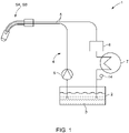
- the welding component cooling system 1 for cooling a welding component SK for example a welding torch SB, contains at least one container 2 for the cooling liquid 3.
- the cooling liquid 3 is formed in particular by water with appropriate additives, which is conducted from the container 2 in a cooling circuit 4.
- the cooling circuit 4 is formed by appropriate cooling lines 5 .
- At least one pump 6 arranged in the cooling circuit 4 conveys the cooling liquid 3 through the cooling lines 5 in the cooling circuit 4.
- At least one heat exchanger 7 is arranged within the cooling circuit 4 in a cooling line 5, via which the heat is dissipated to the environment.
- a device 8 for deionizing the cooling liquid 3 is provided in the cooling circuit 4 according to the invention.
- the deionization device 8 is in the returning cooling line 5 of the cooling circuit 4 arranged. However, it can also be placed at a different point within the cooling circuit 5 .
- the deionization device 8 which can be formed, for example, by a container 9 with mixed-bed resin 10 arranged therein (see FIG 3 ), ensures that the cooling liquid 3 has a very low electrical conductance S, as a result of which negative effects due to electrochemical oxidation taking place in the welding components SK have less of an impact and the welding components SK consequently have a longer service life.
- At least one sensor 14 for measuring the conductance S of the cooling liquid 3 is arranged in the cooling circuit 4, in particular in a cooling line 5 of the cooling circuit 4 that runs back.
- the condition of the cooling liquid 3 can be monitored via the measured values obtained from the sensor 14 for measuring the conductivity S of the cooling liquid 3 and the effect of the deionization by the deionizing device 8 can be measured.
- FIG. 2 shows a schematic block diagram of a further embodiment of a welding component cooling system 1 according to the invention.
- the device 8 for deionizing the cooling liquid 3 is not arranged in a cooling line 5 of the cooling circuit 4, but in a bypass 11 to a cooling line 5 within the cooling circuit 4.
- the flow resistance of the cooling liquid 3 within the cooling circuit 5 through the deionizing device 8 is not negatively influenced.
- the sensor 14 for measuring the conductivity S of the cooling liquid 3 at least one sensor 15 for measuring the flow Q of the cooling liquid 3 and at least one temperature sensor 16 for measuring the temperature T of the cooling liquid 3 are arranged in the cooling circuit 4.
- the sensors 14, 15, 16 are arranged at the same point within the cooling circuit 4 and are preferably formed by a combined sensor.
- the at least one sensor 14 for measuring the conductance S of the coolant 3, the at least one sensor 15 for measuring the Flow rate Q of the cooling liquid 3 and/or the at least one temperature sensor 16 for measuring the temperature T of the cooling liquid 3 and any sensor 21 for measuring the level of the cooling liquid 3 in the container 2 are preferably connected to a control device 17 which is responsible for processing and forwarding of the measured values.
- the measured values of the sensors 14, 15, 16, 21 and the status of the deionizing device 8 can be displayed on a display 18 connected to the control device 17.
- the control device 17 and the display 18 can also be arranged in a welding current source SQ.
- the connections between the control device 17 and the sensors 14, 15, 16, 21 can be wired or wireless.
- At least one filter 19 for filtering the cooling liquid 3 can also be arranged in the cooling circuit 4 .
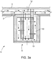
- FIG 3a an embodiment of a device for deionization 8 of the cooling liquid 3 is shown in the form of a container 9 with a mixed-bed resin 10 arranged therein.
- the cooling liquid 3 can on the one hand flow through the mixed-bed resin 10 and/or on the other hand only flow past the surface of the mixed-bed resin 10 in contact.
- the mixed-bed resin 10 can be exchanged in a simple manner, preferably from the underside of the container 9 .
- the mixed-bed resin 10 preferably consists of a mixture of cation resin and anion resin, in particular 40% cation salt and 60% anion salt.
- the Figure 3b and 3c show two further possible embodiments of the deionization device 8, in which the cooling liquid 3 in the container 9 flows past the surface of the mixed-bed resin 10 in contact with it.
- the 3d shows another possible embodiment of the deionizing device 8, the cooling liquid 3 flowing through the mixed-bed resin 10 in the container 9 on the one hand and or, on the other hand, can flow past the mixed-bed resin 10 only touching the surface.
- the welding torch SB has various components B1, B2, B3, B4, such as the nozzle holder as component B1, the gas nozzle holder as component B2, the cooling sleeve as component B3, the inner pipe of the pipe bend as component B4, etc.
- the components B1 and B4 consist of an electrically conductive material M1 and the component B3 consists of a different electrically conductive material M2.
- Component B3 consists of electrically insulating material M3.
- a cooling channel 20 for guiding a cooling liquid 3 runs inside the welding torch SB, which is correspondingly connected to the welding component cooling system 1 described above.
- the cooling channel 20 is partially formed by the above-mentioned components B1, B2, B3, B4 of the welding torch SB.
- the components B1, B2, B3, B4 are connected to one another, for example via a form fit, force fit or material bond.
- An electrochemical cell is thus formed via the cooling liquid 3 flowing in the cooling channel 20 .
- a cooling liquid 3 with a high electrical conductivity S promotes electrochemical oxidation of the anode (sacrificial anode) and thus destruction of the relevant components B1 and/or B2 and/or B4 of the welding torch SB made of the electrically conductive materials M1 and M2.
- various electrically conductive materials M1, M2 can be used for the components B1, B2, B4 of the welding torch SB, the standard potentials of the electrochemical series of which are more differ than 0.7 V.
- aluminum standard potential - 1.66 V
- silver standard potential +0.8 V
- FIG 5 a detailed view of the welding torch SB according to FIG figure 5 along the section line AA to illustrate the components B1, B2, B3, B4 in the area of the cooling channel 20.
- the electrically conductive components B1, B2, B4 of the welding torch SB are arranged in such a way that the minimum path length or liquid column length l min between the components B1 or B4 with component B2 through the cooling channel 20 is less than 12 mm, preferably less than 5 mm.
- the distance l x drawn in shows the distance to be covered by the cooling liquid 3, whereby the distance l x drawn in is more or less the straight line, i.e.
- the actual liquid column length l min is due to the design of the cooling channel 20 - the cooling liquid 3 follows the cooling channel 20 and thus forms a flow curve - significantly longer than that in figure 5 marked distance l x . It was not possible to produce a welding torch SB with the above-mentioned liquid column length l min of less than 12 mm, preferably less than 5 mm, when using conventional cooling liquids 3 .
- the present invention improves the cooling of the welding components SK and their service life and allows, as based on the figures 4 and 5 described, the use of new materials and material combinations for the components of the SK welding components and new designs.
Landscapes
- Engineering & Computer Science (AREA)
- Physics & Mathematics (AREA)
- Mechanical Engineering (AREA)
- Plasma & Fusion (AREA)
- Optics & Photonics (AREA)
- Arc Welding Control (AREA)
- Plasma Technology (AREA)
- Arc Welding In General (AREA)
- Lining Or Joining Of Plastics Or The Like (AREA)
Priority Applications (8)
| Application Number | Priority Date | Filing Date | Title |
|---|---|---|---|
| EP21182634.2A EP4112218A1 (fr) | 2021-06-30 | 2021-06-30 | Système de refroidissement de composants de soudage avec un dispositif de déionisation du liquide de refroidissement, et composant de soudage doté d'un tel système de refroidissement de composants de soudage |
| ES22738638T ES2991707T3 (es) | 2021-06-30 | 2022-06-29 | Sistema de refrigeración de componentes de soldadura con un dispositivo para la desionización del líquido refrigerante, y componente de soldadura con dicho sistema de refrigeración de componentes de soldadura |
| CN202280016888.0A CN116940434B (zh) | 2021-06-30 | 2022-06-29 | 带有冷却液指定装置的焊接部件冷却系统,以及包括该焊接部件冷却系统的焊接部件 |
| PCT/EP2022/067824 WO2023275107A1 (fr) | 2021-06-30 | 2022-06-29 | Système de refroidissement d'élément de soudage à l'aide d'un dispositif d'attribution de liquide de refroidissement, et élément de soudage comprenant un tel système de refroidissement d'élément de soudage |
| US18/287,232 US12059757B2 (en) | 2021-06-30 | 2022-06-29 | Welding component cooling system for cooling a welding component |
| EP22738638.0A EP4255663B1 (fr) | 2021-06-30 | 2022-06-29 | Système de refroidissement de composants de soudage avec un dispositif de déionisation du liquide de refroidissement, et composant de soudage doté d'un tel système de refroidissement de composants de soudage |
| PL22738638.0T PL4255663T3 (pl) | 2021-06-30 | 2022-06-29 | Układ chłodzenia komponentu spawalniczego z urządzeniem do dejonizacji chłodziwa i komponent spawalniczy z takim układem chłodzenia |
| JP2023553047A JP7532683B2 (ja) | 2021-06-30 | 2022-06-29 | 冷却液を指定する装置を備えた溶接部品冷却システム、およびそのような溶接部品冷却システムを含む溶接部品 |
Applications Claiming Priority (1)
| Application Number | Priority Date | Filing Date | Title |
|---|---|---|---|
| EP21182634.2A EP4112218A1 (fr) | 2021-06-30 | 2021-06-30 | Système de refroidissement de composants de soudage avec un dispositif de déionisation du liquide de refroidissement, et composant de soudage doté d'un tel système de refroidissement de composants de soudage |
Publications (1)
| Publication Number | Publication Date |
|---|---|
| EP4112218A1 true EP4112218A1 (fr) | 2023-01-04 |
Family
ID=76730292
Family Applications (2)
| Application Number | Title | Priority Date | Filing Date |
|---|---|---|---|
| EP21182634.2A Withdrawn EP4112218A1 (fr) | 2021-06-30 | 2021-06-30 | Système de refroidissement de composants de soudage avec un dispositif de déionisation du liquide de refroidissement, et composant de soudage doté d'un tel système de refroidissement de composants de soudage |
| EP22738638.0A Active EP4255663B1 (fr) | 2021-06-30 | 2022-06-29 | Système de refroidissement de composants de soudage avec un dispositif de déionisation du liquide de refroidissement, et composant de soudage doté d'un tel système de refroidissement de composants de soudage |
Family Applications After (1)
| Application Number | Title | Priority Date | Filing Date |
|---|---|---|---|
| EP22738638.0A Active EP4255663B1 (fr) | 2021-06-30 | 2022-06-29 | Système de refroidissement de composants de soudage avec un dispositif de déionisation du liquide de refroidissement, et composant de soudage doté d'un tel système de refroidissement de composants de soudage |
Country Status (7)
| Country | Link |
|---|---|
| US (1) | US12059757B2 (fr) |
| EP (2) | EP4112218A1 (fr) |
| JP (1) | JP7532683B2 (fr) |
| CN (1) | CN116940434B (fr) |
| ES (1) | ES2991707T3 (fr) |
| PL (1) | PL4255663T3 (fr) |
| WO (1) | WO2023275107A1 (fr) |
Cited By (1)
| Publication number | Priority date | Publication date | Assignee | Title |
|---|---|---|---|---|
| EP4523827A1 (fr) | 2023-09-14 | 2025-03-19 | Fronius International GmbH | Système de refroidissement pour refroidir un composant de soudage et composant de soudage comprenant un tel système de refroidissement |
Citations (6)
| Publication number | Priority date | Publication date | Assignee | Title |
|---|---|---|---|---|
| EP0072407A2 (fr) | 1981-08-14 | 1983-02-23 | The Perkin-Elmer Corporation | Buse à ailerons de refroidissement pour pistolet de pulvérisation par arc électrique |
| JPS5917617A (ja) * | 1982-07-22 | 1984-01-28 | Toshiba Corp | 冷却水ph制御装置 |
| US4560856A (en) * | 1982-09-01 | 1985-12-24 | Westinghouse Electric Corp. | Pulsed laser machining apparatus |
| EP2025029B1 (fr) | 2006-05-05 | 2011-12-14 | Fronius International GmbH | Système de refroidissement pour pile à combustible |
| EP3501719A1 (fr) * | 2017-12-22 | 2019-06-26 | FRONIUS INTERNATIONAL GmbH | Appareil de soudage doté d'un chalumeau refroidi de soudage et/ou du jeu de flexibles interchangeables et procédé de changement du chalumeau refroidi de soudage et/ou du jeu de flexibles |
| US20210078115A1 (en) * | 2017-09-19 | 2021-03-18 | Alexander Binzel Schweisstechnik Gmbh & Co. Kg | Torch body for thermal joining |
Family Cites Families (6)
| Publication number | Priority date | Publication date | Assignee | Title |
|---|---|---|---|---|
| DE19934367C2 (de) * | 1999-07-22 | 2003-08-21 | Binzel Alexander Gmbh Co Kg | Verfahren zum Kühlen eines Schweiß- oder Schneidbrenners sowie Kühlsystem hierfür |
| DE10104771A1 (de) | 2001-02-02 | 2002-08-08 | Basf Ag | Verfahren und Vorrichtung zum Entionisieren von Kühlmedien für Brennstoffzellen |
| JP3979580B2 (ja) * | 2002-05-31 | 2007-09-19 | 本田技研工業株式会社 | 燃料電池の冷却装置 |
| JP2005345076A (ja) * | 2004-06-07 | 2005-12-15 | Daikin Ind Ltd | 冷却装置 |
| US20100276397A1 (en) * | 2009-05-01 | 2010-11-04 | Baker Hughes Incorporated | Electrically isolated gas cups for plasma transfer arc welding torches, and related methods |
| CN103928840B (zh) * | 2013-01-15 | 2017-05-17 | 沈阳大陆激光柔性制造技术有限公司 | 一种高纯度半导体激光器水冷装置 |
-
2021
- 2021-06-30 EP EP21182634.2A patent/EP4112218A1/fr not_active Withdrawn
-
2022
- 2022-06-29 JP JP2023553047A patent/JP7532683B2/ja active Active
- 2022-06-29 PL PL22738638.0T patent/PL4255663T3/pl unknown
- 2022-06-29 EP EP22738638.0A patent/EP4255663B1/fr active Active
- 2022-06-29 ES ES22738638T patent/ES2991707T3/es active Active
- 2022-06-29 US US18/287,232 patent/US12059757B2/en active Active
- 2022-06-29 WO PCT/EP2022/067824 patent/WO2023275107A1/fr not_active Ceased
- 2022-06-29 CN CN202280016888.0A patent/CN116940434B/zh active Active
Patent Citations (7)
| Publication number | Priority date | Publication date | Assignee | Title |
|---|---|---|---|---|
| EP0072407A2 (fr) | 1981-08-14 | 1983-02-23 | The Perkin-Elmer Corporation | Buse à ailerons de refroidissement pour pistolet de pulvérisation par arc électrique |
| US4405853A (en) * | 1981-08-14 | 1983-09-20 | Metco Inc. | Plasma spray gun with cooling fin nozzle and deionizer |
| JPS5917617A (ja) * | 1982-07-22 | 1984-01-28 | Toshiba Corp | 冷却水ph制御装置 |
| US4560856A (en) * | 1982-09-01 | 1985-12-24 | Westinghouse Electric Corp. | Pulsed laser machining apparatus |
| EP2025029B1 (fr) | 2006-05-05 | 2011-12-14 | Fronius International GmbH | Système de refroidissement pour pile à combustible |
| US20210078115A1 (en) * | 2017-09-19 | 2021-03-18 | Alexander Binzel Schweisstechnik Gmbh & Co. Kg | Torch body for thermal joining |
| EP3501719A1 (fr) * | 2017-12-22 | 2019-06-26 | FRONIUS INTERNATIONAL GmbH | Appareil de soudage doté d'un chalumeau refroidi de soudage et/ou du jeu de flexibles interchangeables et procédé de changement du chalumeau refroidi de soudage et/ou du jeu de flexibles |
Cited By (2)
| Publication number | Priority date | Publication date | Assignee | Title |
|---|---|---|---|---|
| EP4523827A1 (fr) | 2023-09-14 | 2025-03-19 | Fronius International GmbH | Système de refroidissement pour refroidir un composant de soudage et composant de soudage comprenant un tel système de refroidissement |
| WO2025056729A1 (fr) | 2023-09-14 | 2025-03-20 | Fronius International Gmbh | Système de refroidissement pour refroidir un élément de soudage, et élément de soudage comprenant un tel système de refroidissement |
Also Published As
| Publication number | Publication date |
|---|---|
| ES2991707T3 (es) | 2024-12-04 |
| CN116940434B (zh) | 2024-08-23 |
| PL4255663T3 (pl) | 2025-01-20 |
| CN116940434A (zh) | 2023-10-24 |
| EP4255663A1 (fr) | 2023-10-11 |
| US12059757B2 (en) | 2024-08-13 |
| US20240198448A1 (en) | 2024-06-20 |
| WO2023275107A1 (fr) | 2023-01-05 |
| EP4255663B1 (fr) | 2024-08-28 |
| JP7532683B2 (ja) | 2024-08-13 |
| EP4255663C0 (fr) | 2024-08-28 |
| JP2024527212A (ja) | 2024-07-24 |
Similar Documents
| Publication | Publication Date | Title |
|---|---|---|
| DE60125769T2 (de) | Verbessertes elektroentionisierungssystem | |
| EP2008750A1 (fr) | Chalumeau de soudage TIG | |
| DE68911912T2 (de) | Funkenerosionsmaschine. | |
| DE112012006422T5 (de) | Reinigungsvorrichtung für eine elektroerosive Bearbeitungsflüssigkeit und Reinigungsverfahren für eine elektroerosive Bearbeitungsflüssigkeit | |
| DE2020096A1 (de) | Mit elektrischer Entladung arbeitende Materialabtragvorrichtung(Elektroerosionsmaschine) | |
| EP4255663B1 (fr) | Système de refroidissement de composants de soudage avec un dispositif de déionisation du liquide de refroidissement, et composant de soudage doté d'un tel système de refroidissement de composants de soudage | |
| WO2009060068A1 (fr) | Procédé permettant de faire fonctionner un système de brasage à la vague, avec utilisation de polyéther perfluoré pour la réaction avec des impuretés contenant du plomb | |
| DE3419629C2 (de) | Adaptives Regelverfahren zur Steuerung von Betriebsparametern beim funkenerosiven Schneiden und funkenerosive Schneidanlage hierfür | |
| EP2669037B1 (fr) | Réduction de fumée de soudage | |
| EP2897444B1 (fr) | Circuit d'alimentation de courant DEL | |
| DE2244730A1 (de) | Anzeigeeinrichtung zum schutz von anoden in einer elektrolytischen zelle mit fliessender quecksilberkathode | |
| EP3142136A1 (fr) | Dispositif de commande d'un element de commutation | |
| EP3283192A1 (fr) | Dispositif filtrant et élément filtrant | |
| EP3747655B1 (fr) | Tête d'impression et procédé de fabrication d'une tête d'impression | |
| DE102014218186B4 (de) | Verfahren zum Durchführen eines Schweißprozesses, Schweißgerät und Drahtrolle für ein solches Schweißgerät | |
| EP2829162B1 (fr) | Électrode à plasma pour une torche à plasma d'arc avec extrémité d'électrode échangeable | |
| WO2005039242A1 (fr) | Dispositif de chauffage pourvu d'un element ptc, conçu en particulier pour un vehicule automobile | |
| EP1178553A2 (fr) | Dispositif pour le traitement d'un mélange combustible-réfrigérant dans un système de piles à combustible | |
| EP1093392A1 (fr) | Dispositif de filtrage a plusieurs etages | |
| DE102005036664B4 (de) | Partikelfilter für ein Brennstoffzellenkühlmittel | |
| DE202015106880U1 (de) | Grenzstanddetektor zum Überwchen des Füllstands eines heissen, flüssigen Mediums | |
| WO2002016113A9 (fr) | Dispositif pour filtrer des substances liquides, corps support et procede permettant d'actionner ledit dispositif | |
| DE3537048A1 (de) | Zufuehrvorrichtung fuer eine arbeitsloesung fuer eine mit drahtschneidelektrode ausgebildete, mit elektrischer entladung arbeitende bearbeitungsvorrichtung | |
| EP4017669B1 (fr) | Procédé de détermination de l'usure d'un tube de contact lors d'un procédé de soudage assisté par robot | |
| AT979U1 (de) | Schweissvorrichtung mit einer schweissstromquelle, einem schweissbrenner und einer kühlvorrichtung |
Legal Events
| Date | Code | Title | Description |
|---|---|---|---|
| PUAI | Public reference made under article 153(3) epc to a published international application that has entered the european phase |
Free format text: ORIGINAL CODE: 0009012 |
|
| STAA | Information on the status of an ep patent application or granted ep patent |
Free format text: STATUS: THE APPLICATION HAS BEEN PUBLISHED |
|
| AK | Designated contracting states |
Kind code of ref document: A1 Designated state(s): AL AT BE BG CH CY CZ DE DK EE ES FI FR GB GR HR HU IE IS IT LI LT LU LV MC MK MT NL NO PL PT RO RS SE SI SK SM TR |
|
| STAA | Information on the status of an ep patent application or granted ep patent |
Free format text: STATUS: THE APPLICATION IS DEEMED TO BE WITHDRAWN |
|
| 18D | Application deemed to be withdrawn |
Effective date: 20230705 |