EP4112246A1 - Montageanordnung für ein haarschneidegerät - Google Patents
Montageanordnung für ein haarschneidegerät Download PDFInfo
- Publication number
- EP4112246A1 EP4112246A1 EP21183450.2A EP21183450A EP4112246A1 EP 4112246 A1 EP4112246 A1 EP 4112246A1 EP 21183450 A EP21183450 A EP 21183450A EP 4112246 A1 EP4112246 A1 EP 4112246A1
- Authority
- EP
- European Patent Office
- Prior art keywords
- base
- head
- mounting assembly
- coupling
- movement
- Prior art date
- Legal status (The legal status is an assumption and is not a legal conclusion. Google has not performed a legal analysis and makes no representation as to the accuracy of the status listed.)
- Withdrawn
Links
Images

Classifications
-
- B—PERFORMING OPERATIONS; TRANSPORTING
- B26—HAND CUTTING TOOLS; CUTTING; SEVERING
- B26B—HAND-HELD CUTTING TOOLS NOT OTHERWISE PROVIDED FOR
- B26B21/00—Razors of the open or knife type; Safety razors or other shaving implements of the planing type; Hair-trimming devices involving a razor-blade; Equipment therefor
- B26B21/40—Details or accessories
-
- B—PERFORMING OPERATIONS; TRANSPORTING
- B26—HAND CUTTING TOOLS; CUTTING; SEVERING
- B26B—HAND-HELD CUTTING TOOLS NOT OTHERWISE PROVIDED FOR
- B26B19/00—Clippers or shavers operating with a plurality of cutting edges, e.g. hair clippers, dry shavers
- B26B19/38—Details of, or accessories for, hair clippers, or dry shavers, e.g. housings, casings, grips, guards
- B26B19/3853—Housing or handle
- B26B19/386—Means for attaching the head thereto
-
- B—PERFORMING OPERATIONS; TRANSPORTING
- B26—HAND CUTTING TOOLS; CUTTING; SEVERING
- B26B—HAND-HELD CUTTING TOOLS NOT OTHERWISE PROVIDED FOR
- B26B19/00—Clippers or shavers operating with a plurality of cutting edges, e.g. hair clippers, dry shavers
- B26B19/02—Clippers or shavers operating with a plurality of cutting edges, e.g. hair clippers, dry shavers of the reciprocating-cutter type
- B26B19/04—Cutting heads therefor; Cutters therefor; Securing equipment thereof
- B26B19/06—Cutting heads therefor; Cutters therefor; Securing equipment thereof involving co-operating cutting elements both of which have shearing teeth
- B26B19/063—Movable or adjustable cutting head
-
- B—PERFORMING OPERATIONS; TRANSPORTING
- B26—HAND CUTTING TOOLS; CUTTING; SEVERING
- B26B—HAND-HELD CUTTING TOOLS NOT OTHERWISE PROVIDED FOR
- B26B19/00—Clippers or shavers operating with a plurality of cutting edges, e.g. hair clippers, dry shavers
- B26B19/02—Clippers or shavers operating with a plurality of cutting edges, e.g. hair clippers, dry shavers of the reciprocating-cutter type
- B26B19/04—Cutting heads therefor; Cutters therefor; Securing equipment thereof
- B26B19/048—Complete cutting head being movable
-
- B—PERFORMING OPERATIONS; TRANSPORTING
- B26—HAND CUTTING TOOLS; CUTTING; SEVERING
- B26B—HAND-HELD CUTTING TOOLS NOT OTHERWISE PROVIDED FOR
- B26B21/00—Razors of the open or knife type; Safety razors or other shaving implements of the planing type; Hair-trimming devices involving a razor-blade; Equipment therefor
- B26B21/40—Details or accessories
- B26B21/52—Handles, e.g. tiltable, flexible
- B26B21/521—Connection details, e.g. connection to razor heads
Definitions
- the invention relates to a mounting assembly for a hair cutting appliance, and a hair cutting appliance comprising the mounting assembly.
- Hair cutting appliances such a manual or electric razors typically have a blade head mounted to a handle, and the blade head may be pivotably attached to the handle to rotate relative to the body about an axis, such as WO 2015/074882 .
- pivoting movement may have a hard stop providing a sudden limit to the pivoting movement of the head, which is unpleasant for the user and can result in poor cutting performance on complex geometries such as faces.
- a mounting assembly for a hair cutting appliance comprising: a head configured to receive a cutting unit; a base, wherein the head is mounted to the base via a pair of arms to form a linkage, each arm being coupled at a joint to a head coupling on the head, and coupled at a joint to a respective base coupling on the base, the base couplings spaced apart along a movement line, and each joint configured to permit pivoting movement about parallel pivot axes; a stroke limiter configured to obstruct pivoting movement of the head relative to the base beyond a limit; wherein at least one of the base couplings is a flexible base coupling which is elastically mounted to a body of the base such that the respective flexible base coupling is moveable relative to the body in a direction having a component which is parallel to the movement line and away from the other base coupling, to permit pivoting movement of the head relative to the base beyond the limit imposed by the stroke limiter.
- the pivoting movement of the head relative to the base may include the head pivoting about a virtual axis, which is parallel to the pivot axes.
- Each arm may be coupled to a different respective head coupling to permit pivoting movement about different parallel pivot axes thereby forming a four-bar linkage, such that the head is pivotably moveable relative to the base.
- the stroke limiter may be configured to obstruct pivoting movement of the four-bar linkage to thereby inhibit pivoting movement of the head relative to the base beyond the limit.
- the stroke limiter may comprise a tab protruding from the head, the tab being arranged to engage with at least one of the arms to obstruct movement of the four-bar linkage within the movement plane.
- the mounting assembly may comprise a primary spring which is configured to engage with the arms to bias the four-bar linkage to the limit.
- Both base couplings on the handle may be flexible base couplings.
- Each flexible base coupling may be mounted to the body of the base on a cantilevered elastic beam which permits movement of the base coupling relative to the body in the direction having a component which is parallel to the movement line and away from the other base coupling.
- the body may comprise a stop for each flexible base coupling, wherein the stop may be configured to abut the elastic beam to limit movement of the elastic beam in a direction towards the other base coupling.
- the base may further comprise a pretension spring which is configured to bias the elastic beam for each flexible base coupling towards the stop.
- the pretension spring may be configured to bias the flexible base coupling to abut the stop.
- the stiffness of the pretension spring may be higher than the stiffness of the elastic beam in the movement plane.
- Each base coupling may be a ball bearing configured to cooperate with a corresponding ball socket on the respective arm.
- the base couplings may be spaced apart and aligned within the movement plane.
- Each flexible base coupling may be moveable relative to the body such that the base couplings move only within a single plane.
- the elastic beam on which the flexible base coupling is mounted may not permit movement in a direction parallel to the pivot axes.
- a hair cutting appliance comprising a mounting assembly according to the first aspect.
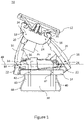
- Fig. 1 shows a cross-sectional view of an example mounting assembly 10 for a hair cutting appliance, in a first position.
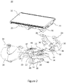
- Fig. 2 shows an exploded isometric view of the same mounting assembly 10.
- the mounting assembly 10 comprises a head 12 which is configured to receive a cutting unit, such as a blade or electric trimming attachment, and a base 14 for connection to a handle configured to be held by a user.
- a cutting unit such as a blade or electric trimming attachment
- a base 14 for connection to a handle configured to be held by a user.
- the base may be integral with a handle.
- the head 12 is mounted to the base 14 via a pair of arms 16. Each arm 16 is connected at a joint 18 to respective head couplings 20 and connected at a joint 18 to respective base couplings 22.
- the arms 16 each comprise two diverging strands in a U-shape such that each arm 16 is connected to the base 14 at a single base coupling 22 at the apex of the U-shape, and such that each arm 16 is connected at the two ends of the U-shape to a respective head coupling 20. Therefore, there are two base couplings 22 on the base 14, and there are four head couplings 20 on the head 12. The head 12 is supported relative to the base 14 by the four head couplings 20 which connect to the arms 16.
- each arm may comprise a single strand to form an I-shape such that the head is supported by the arms at only two head couplings in total, or the arms may comprise more than two diverging strands so that the coupler link is supported by the arms at more than two coupler joins per arm.
- Each arm may have a different number of diverging strands to support the coupler link at, for example 3 or 5 coupler joins.
- the arms may comprise two diverging strands in the form of a T, V or Y shape such that each arm supports the coupler link at two coupler joins.
- Each joint 18 is configured to permit pivoting movement between the respective arms 16, head 12 and base 14, about parallel primary pivot axes 24 (shown as going into the page on Fig. 1 ) to form a four-bar linkage in which each arm 16 is one bar, the head 12 is one bar and the base 14 is one bar of the four-bar linkage.
- the four-bar linkage is therefore permitted to move within a movement plane which is perpendicular to the primary pivot axes 24.
- the two head couplings 20 connecting the same arm 16 to the head 12 are spaced apart only in a direction parallel to the primary pivot axes 24 such that they share a primary pivot axis 24 (i.e. their pivot axes are collinear).
- the head couplings 20 connecting different arms 16 to the head 12 are spaced apart within the movement plane (i.e. perpendicular to the primary pivot axes 24), such that the joint 18 at head couplings 20 for different arms 16 each permit pivoting movement about different parallel primary pivot axes 24.
- the base couplings 22 are also spaced apart within the movement plane along a movement line, which in this example is the secondary pivot axis 30.
- the four-bar linkage therefore permits pivoting movement of the head 12 relative to the base 14 about a virtual pivot axis, where the virtual pivot axis is parallel to the primary pivot axes 24 of the joints 18.
- the pivot axes of all of the joints at the head couplings are collinear, so that the head no longer forms a bar of the linkage, and such that the arms, head and base form a three-bar linkage.
- the head is pivotable about the primary pivot axis which passes through the head couplings.
- Each of the head couplings 20 in this example are linear bearings, and so only permit pivoting movement about the parallel primary pivot axes 24 within the movement plane.
- Each of the base couplings 22 in this example are ball bearings which are configured to cooperate with a corresponding ball socket 32 on the respective arms 16 to form a ball joint (best shown in Fig. 2 ).
- the ball joints permit pivoting movement about three perpendicular pivot axes.
- the ball joints i.e. the joints 18 at the base couplings 22 in this example
- the secondary pivot axis 30 permits movement of the whole four-bar linkage in unison such that the primary pivot axes 24 also pivot about the secondary pivot axis 30, thereby also pivoting the movement plane about the secondary pivot axis 30.
- the ball bearings may be linear bearings such that there is no pivoting movement about a secondary pivot axis. It will be appreciated that in other examples, the ball bearing may be disposed on the head and the linear bearings may be disposed on the base.
- the mounting assembly 10 comprises a stroke limiter 26 which is configured to obstruct pivoting movement of the head relative to the base beyond a limit.
- the stroke limiter 26 is configured to obstruct pivoting movement of the four-bar linkage to inhibit pivoting movement of the head 12.
- the stroke limiter may merely limit pivoting movement of the head about the primary pivot axis passing through the head coupling.
- the stroke limiter 26 in this example comprises a tab protruding from the head 12 in a direction towards the base 14, such that the tab is disposed between the pair of arms 16.
- the tab is arranged to engage with each of the arms 16 at a respective limit to obstruct movement of the four-bar linkage within the movement plane.
- Fig. 1 shows the tab engaged with one of the arms 16 at a limit.
- the four-bar linkage is therefore constrained to move within the movement plane between limits imposed by the stroke limiter 26 engaging with each arm 16.
- the tab may be disposed on the head outside the arms and may be configured to engage the outside of one of the arms to obstruct movement of the four-bar linkage beyond a limit.
- the tab may be disposed on one of the arms or on the base and may be configured to engage with the head or the base to obstruct pivoting movement of the four-bar linkage or pivoting movement of the head.
- the stroke limiter may only obstruct pivoting movement of the head in one direction, or may obstruct pivoting movement of the head in both pivoting directions.
- the mounting assembly 10 further comprises a pair of primary springs 34 in this example which are attached to the base 14 and are each configured to engage with one of the arms 16 to bias the four-bar linkage to one of the limits (i.e. to the first position shown in Fig. 1 ).
- each primary spring 34 comprises a leaf spring which abuts an inner protrusion 36 on one of the arms 16 to push the protrusion 36 upwards. Both protrusions 36 are on the same arm 16 and therefore the primary springs 34 both act in unison to pivot the arm 16 until the stroke limiter 26 obstructs further pivoting movement at a limit in the first position, in this example, by engaging the same arm 16.
- the primary springs 34 are spaced apart along a direction parallel to the primary pivoting axis 24 (i.e. they are disposed on either side of the movement plane). It will be appreciated that only one primary spring is necessary to provide the biasing force to bias the head to the first position shown in Fig. 1 , and that there may be no primary springs to bias the head to the first position. It will also be appreciated that the primary springs may be disposed elsewhere, such as on the arms or the head, to bias the four-bar linkage to the limit.
- the base couplings 22 are flexible base couplings 22 which are mounted to the body 38 of the base 14 on a cantilevered elastic beam 40 and moveable to a second position.
- Fig. 3 shows the mounting assembly 10 of Fig. 1 in the second position.
- the elastic beam 40 is attached at one end to the body 38, and the base coupling 22 (i.e. the ball bearing) is mounted to the other end of the elastic beam 40 to form the flexible base coupling 22.
- the elastic beam 40 therefore permits movement of the flexible base coupling 22 relative to the base body 38 in a direction having a component which is parallel to the movement line (i.e. the secondary pivot axis 30 in this example), to the second position, on application of an external force.
- the primary pivot axis 24 of the joint 18 has moved with the flexible base coupling 22. It will be appreciated that in some examples, there may be only one flexible base coupling.
- the elastic beam 40 permits movement only in a single plane.
- the stiffness of the elastic beam 40 prevents movement of the flexible base coupling 22 in a direction out of the single plane.
- the elastic mounting of the base coupling to the base may permit movement of the flexible base only within the movement plane, such as movement along the secondary pivot axis, for example, if the elastic mounting is in the form of a simple linear spring, such as a coil spring.
- the stroke limiter 26 obstructs movement of the head 12 relative to the base 14 beyond the limit (as shown in Fig. 1 ). If further external force is applied, one of the flexible base couplings 22 is forced to move within the single plane from the first position, towards the second position in a direction having a component which is parallel to the movement line, which is away from the other base coupling 22. This makes the bar of the four-bar linkage defined by the base 14 longer, thereby changing the layout of the four-bar linkage and permitting pivoting movement of the head 12 relative to the base 14 beyond the limit imposed by the stroke limiter 26.
- both base couplings 22 are flexible base couplings 22 can act as a suspension unit, when excessive force is applied to the head 12 in the direction of the base 14, the flexible base couplings 22 can both move to provide some suspension. This can improve user comfort.
- the body 38 of the base 14 comprises a stop 42 for each flexible base coupling 22. Therefore, the base 14 comprises two stops 42, which are on opposing sides of the body 38. Each stop 42 is configured to abut the elastic beam 40 on which the respective base coupling 22 is mounted (or obstruct any other flexible mounting) to limit movement of the elastic beam 40 in a direction towards the other base coupling 22.
- the base 14 further comprises a pretension spring 44 which is configured to bias the elastic beam 40, and thereby the flexible base coupling 22, towards the stop 42, to abut the stop 42.
- the pretension spring is in the form of a clip which is disposed around the stops 42, and acts on both stops 42 from opposing sides.
- each stop may have its own pretension spring which limits movement of the flexible mounting.
- the pretension spring 44 has a higher stiffness than the elastic beam 40 in the single plane in which the flexible base couplings 22 are configured to move, such that it provides a smooth transition of movement for the head 12 beyond the limit imposed by the stroke limiter 26.
- the base coupling may be mounted on a beam which is pivotably mounted to the body of the base, and the pretension spring may provide the elastic movement of the base coupling.
Landscapes
- Life Sciences & Earth Sciences (AREA)
- Forests & Forestry (AREA)
- Engineering & Computer Science (AREA)
- Mechanical Engineering (AREA)
- Dry Shavers And Clippers (AREA)
Priority Applications (7)
| Application Number | Priority Date | Filing Date | Title |
|---|---|---|---|
| EP21183450.2A EP4112246A1 (de) | 2021-07-02 | 2021-07-02 | Montageanordnung für ein haarschneidegerät |
| EP22735465.1A EP4363177B1 (de) | 2021-07-02 | 2022-06-29 | Montageanordnung für ein haarschneidegerät |
| JP2023574324A JP7803352B2 (ja) | 2021-07-02 | 2022-06-29 | 毛髪切断器具用取付アセンブリ |
| PCT/EP2022/067898 WO2023275143A1 (en) | 2021-07-02 | 2022-06-29 | Mounting assembly for a hair cutting appliance |
| US18/574,515 US20240335964A1 (en) | 2021-07-02 | 2022-06-29 | Mounting assembly for a hair cutting appliance |
| CN202210774634.7A CN115556148A (zh) | 2021-07-02 | 2022-07-01 | 用于毛发切割器具的安装组件 |
| CN202221686133.5U CN218557161U (zh) | 2021-07-02 | 2022-07-01 | 用于毛发切割器具的安装组件和毛发切割器具 |
Applications Claiming Priority (1)
| Application Number | Priority Date | Filing Date | Title |
|---|---|---|---|
| EP21183450.2A EP4112246A1 (de) | 2021-07-02 | 2021-07-02 | Montageanordnung für ein haarschneidegerät |
Publications (1)
| Publication Number | Publication Date |
|---|---|
| EP4112246A1 true EP4112246A1 (de) | 2023-01-04 |
Family
ID=76764916
Family Applications (2)
| Application Number | Title | Priority Date | Filing Date |
|---|---|---|---|
| EP21183450.2A Withdrawn EP4112246A1 (de) | 2021-07-02 | 2021-07-02 | Montageanordnung für ein haarschneidegerät |
| EP22735465.1A Active EP4363177B1 (de) | 2021-07-02 | 2022-06-29 | Montageanordnung für ein haarschneidegerät |
Family Applications After (1)
| Application Number | Title | Priority Date | Filing Date |
|---|---|---|---|
| EP22735465.1A Active EP4363177B1 (de) | 2021-07-02 | 2022-06-29 | Montageanordnung für ein haarschneidegerät |
Country Status (5)
| Country | Link |
|---|---|
| US (1) | US20240335964A1 (de) |
| EP (2) | EP4112246A1 (de) |
| JP (1) | JP7803352B2 (de) |
| CN (2) | CN218557161U (de) |
| WO (1) | WO2023275143A1 (de) |
Families Citing this family (1)
| Publication number | Priority date | Publication date | Assignee | Title |
|---|---|---|---|---|
| EP3978211A1 (de) * | 2020-10-01 | 2022-04-06 | Koninklijke Philips N.V. | Montageanordnung und haarschneidegerät |
Citations (4)
| Publication number | Priority date | Publication date | Assignee | Title |
|---|---|---|---|---|
| EP1405701A1 (de) * | 2002-10-01 | 2004-04-07 | The Gillette Company | Gelenkgetriebe mit virtueller Schwenkachse für Haarentfernungsgerät mit Schwingkopf |
| EP2875916A1 (de) * | 2013-11-22 | 2015-05-27 | Koninklijke Philips N.V. | Montageeinheit und Haarschneidegerät |
| WO2015074882A1 (en) | 2013-11-22 | 2015-05-28 | Koninklijke Philips N.V. | Linkage unit and hair cutting appliance |
| EP3546147A1 (de) * | 2018-03-29 | 2019-10-02 | Braun GmbH | Haarentfernungsvorrichtung |
Family Cites Families (5)
| Publication number | Priority date | Publication date | Assignee | Title |
|---|---|---|---|---|
| CA2235115A1 (en) * | 1997-06-16 | 1998-12-16 | David C. Coffin | Razor providing pivoting and swivelling razor head support |
| DE102008031132A1 (de) | 2008-07-01 | 2010-01-07 | Braun Gmbh | Elektrisches Kleingerät zum Entfernen von Haaren |
| KR101701710B1 (ko) | 2009-05-28 | 2017-02-03 | 코닌클리케 필립스 엔.브이. | 선회 장치 |
| US20160121496A1 (en) * | 2014-10-30 | 2016-05-05 | The Gillette Company | Shaving razor system including at least one magnetic element |
| EP3546156B1 (de) * | 2018-03-30 | 2021-03-10 | The Gillette Company LLC | Rasierergriff mit einem schwenkbaren teil |
-
2021
- 2021-07-02 EP EP21183450.2A patent/EP4112246A1/de not_active Withdrawn
-
2022
- 2022-06-29 JP JP2023574324A patent/JP7803352B2/ja active Active
- 2022-06-29 WO PCT/EP2022/067898 patent/WO2023275143A1/en not_active Ceased
- 2022-06-29 US US18/574,515 patent/US20240335964A1/en active Pending
- 2022-06-29 EP EP22735465.1A patent/EP4363177B1/de active Active
- 2022-07-01 CN CN202221686133.5U patent/CN218557161U/zh active Active
- 2022-07-01 CN CN202210774634.7A patent/CN115556148A/zh active Pending
Patent Citations (4)
| Publication number | Priority date | Publication date | Assignee | Title |
|---|---|---|---|---|
| EP1405701A1 (de) * | 2002-10-01 | 2004-04-07 | The Gillette Company | Gelenkgetriebe mit virtueller Schwenkachse für Haarentfernungsgerät mit Schwingkopf |
| EP2875916A1 (de) * | 2013-11-22 | 2015-05-27 | Koninklijke Philips N.V. | Montageeinheit und Haarschneidegerät |
| WO2015074882A1 (en) | 2013-11-22 | 2015-05-28 | Koninklijke Philips N.V. | Linkage unit and hair cutting appliance |
| EP3546147A1 (de) * | 2018-03-29 | 2019-10-02 | Braun GmbH | Haarentfernungsvorrichtung |
Also Published As
| Publication number | Publication date |
|---|---|
| JP7803352B2 (ja) | 2026-01-21 |
| EP4363177A1 (de) | 2024-05-08 |
| US20240335964A1 (en) | 2024-10-10 |
| EP4363177B1 (de) | 2025-01-29 |
| CN115556148A (zh) | 2023-01-03 |
| CN218557161U (zh) | 2023-03-03 |
| WO2023275143A1 (en) | 2023-01-05 |
| JP2024520632A (ja) | 2024-05-24 |
Similar Documents
| Publication | Publication Date | Title |
|---|---|---|
| US11298843B2 (en) | Shaving cartridges pivotable about two axes | |
| US10933547B2 (en) | Shaving handle system for holding a cartridge pivotable about two axes | |
| JP5079947B2 (ja) | ひげ剃り組立品 | |
| EP4363177B1 (de) | Montageanordnung für ein haarschneidegerät | |
| US11090825B2 (en) | Shaving cartridge | |
| CN216464750U (zh) | 安装组件、毛发切割器具和成套部件 | |
| EP4137282A1 (de) | Montageanordnung für ein haarschneidegerät | |
| EP4363176B1 (de) | Montageanordnung | |
| US12583136B2 (en) | Mounting assembly | |
| CN119300964B (zh) | 安装组件 | |
| RU2790382C1 (ru) | Установочный узел и приспособление для срезания волос |
Legal Events
| Date | Code | Title | Description |
|---|---|---|---|
| PUAI | Public reference made under article 153(3) epc to a published international application that has entered the european phase |
Free format text: ORIGINAL CODE: 0009012 |
|
| STAA | Information on the status of an ep patent application or granted ep patent |
Free format text: STATUS: THE APPLICATION HAS BEEN PUBLISHED |
|
| AK | Designated contracting states |
Kind code of ref document: A1 Designated state(s): AL AT BE BG CH CY CZ DE DK EE ES FI FR GB GR HR HU IE IS IT LI LT LU LV MC MK MT NL NO PL PT RO RS SE SI SK SM TR |
|
| STAA | Information on the status of an ep patent application or granted ep patent |
Free format text: STATUS: THE APPLICATION IS DEEMED TO BE WITHDRAWN |
|
| 18D | Application deemed to be withdrawn |
Effective date: 20230705 |