EP4112249B1 - Haarentfernungsvorrichtung - Google Patents
Haarentfernungsvorrichtung Download PDFInfo
- Publication number
- EP4112249B1 EP4112249B1 EP21182056.8A EP21182056A EP4112249B1 EP 4112249 B1 EP4112249 B1 EP 4112249B1 EP 21182056 A EP21182056 A EP 21182056A EP 4112249 B1 EP4112249 B1 EP 4112249B1
- Authority
- EP
- European Patent Office
- Prior art keywords
- snap fit
- fit connector
- cutting head
- removal device
- hair removal
- Prior art date
- Legal status (The legal status is an assumption and is not a legal conclusion. Google has not performed a legal analysis and makes no representation as to the accuracy of the status listed.)
- Active
Links
Images


Classifications
-
- B—PERFORMING OPERATIONS; TRANSPORTING
- B26—HAND CUTTING TOOLS; CUTTING; SEVERING
- B26B—HAND-HELD CUTTING TOOLS NOT OTHERWISE PROVIDED FOR
- B26B19/00—Clippers or shavers operating with a plurality of cutting edges, e.g. hair clippers, dry shavers
- B26B19/20—Clippers or shavers operating with a plurality of cutting edges, e.g. hair clippers, dry shavers with provision for shearing hair of preselected or variable length
-
- B—PERFORMING OPERATIONS; TRANSPORTING
- B26—HAND CUTTING TOOLS; CUTTING; SEVERING
- B26B—HAND-HELD CUTTING TOOLS NOT OTHERWISE PROVIDED FOR
- B26B19/00—Clippers or shavers operating with a plurality of cutting edges, e.g. hair clippers, dry shavers
- B26B19/02—Clippers or shavers operating with a plurality of cutting edges, e.g. hair clippers, dry shavers of the reciprocating-cutter type
- B26B19/04—Cutting heads therefor; Cutters therefor; Securing equipment thereof
- B26B19/06—Cutting heads therefor; Cutters therefor; Securing equipment thereof involving co-operating cutting elements both of which have shearing teeth
-
- B—PERFORMING OPERATIONS; TRANSPORTING
- B26—HAND CUTTING TOOLS; CUTTING; SEVERING
- B26B—HAND-HELD CUTTING TOOLS NOT OTHERWISE PROVIDED FOR
- B26B19/00—Clippers or shavers operating with a plurality of cutting edges, e.g. hair clippers, dry shavers
- B26B19/38—Details of, or accessories for, hair clippers, or dry shavers, e.g. housings, casings, grips, guards
- B26B19/3806—Accessories
- B26B19/3813—Attachments
Definitions
- the invention relates to a hair removal device, in particular an electric shaver or a hair trimmer, comprising: a handle having a motor, a cutting head having a blade unit with a first and second blade for cutting hair, said blade unit being driven by said motor, so that at least one of said first and second blade reciprocates to the other in a reciprocation direction, said cutting head having a first snap fit connector and a comb attachment releasably attachable to the cutting head, said comb attachment having a second snap fit connector provided to engage by snap fit connection with the first snap fit connector for attaching the comb attachment at the cutting head.
- combs are provided which cooperate with a cutting edge and which add more distance between the cutting edge and the skin surface.
- Other attachments may be used for e.g. assuring that the sharp cutting edge is safely kept away from thin sensible skin areas.
- Those attachments may be releasably attached to a cutting head of a hair trimmer or an electric shaver and exchanged with each other in accordance with the desired use.
- the attachments are attached to the cutting head by means of latches, hooks, snap fit or other types.
- US-A-5259115 discloses a hair trimmer device have a snap fit hook connected to the handle part and being provided with a film hinge in order to flex when another snap fit hook is to be engaged as part of a comb attachment. From EP-A-1632321 and EP-A-0176372 are further trimmers with comb attachments known.
- a more particular objective underlying the invention is to provide for a hair removal device having an improved snap fit connection between a cutting head and a comb attachment.
- Said hair removal device in particular an electric shaver or a hair trimmer, comprising: a handle having a motor , a cutting head having a blade unit with a first and second blade for cutting hair, said blade unit being driven by said motor, so that at least one of said first and second blade reciprocates relative to the other in a reciprocation direction , said cutting head having a first snap fit connector and a comb attachment releasably attachable to the cutting head , said comb attachment having a second snap fit connector provided to engage by snap fit connection with the first snap fit connector for attaching the comb attachment at the cutting head , wherein said first snap fit connector is at least one of: formed in a shape to flex, made of a material to flex or supported to flex, so that said first snap fit connector is able to flex when brought into engagement with said second snap fit connector.
- a flexing form of said first snap fit connector may be achieved by thinner material thicknesses in the area of the snap fit projection or by an outer shape of the surrounding area which allows flexing.
- An example of a flexing material is rubber or TPE elastic thermoplastic in the surrounding area of the snap fit or the projection itself.
- the first snap fit connector may also or alternatively be supported to flex.
- the snap fit projection may be provided on a wall element that is at least at some sides unconnected to the rest of the housing so that at least one or more slots or free space(s) is/are created adjacent to the snap fit projection. Such lack of connection to other housing parts may e.g. create a flexing tongue onto which the snap fit projection is provided.
- This arrangement of a flexing first snap fit connector being provided at the cutting head provides several advantages. Usually the provision of flexibility to a snap fit connector increase it thickness or bulkiness in order to allow differentiating between walls which would flex and those which are not desired to flex. The cutting head provided sufficient space for that without adding anything to the dimensions of the comb attachment.
- the comb attachment 10 is provided with at least one row of comb teeth at a frontal side 13, a top skin side 14, an inside hair cutting head coupling side 15 and at least one lateral side 16a, 16b, wherein the at least one lateral side 16a, 16b is provided with a wall portion 18a, 18b that forms a finger gripping area 17a, 17b on the outside and the second snap fit connector 11 on the inside, so that one side of the wall portion is provided with the finger gripping area 17a, 17b and the opposite side of the wall portion 18a, 18b is provided with the second snap fit connector 11a, 11b.
- the finger grip portion for attaching and detaching the comb onto the cutting head is the same area in which the second snap fit connector is provided (only provided on opposing sides of the same wall portion of the comb attachment). It is usually without adding further design features difficult to release said snap fit connection if at the same time the fingers press at said snap fit connection in order to grip the attachment.
- the comb attachment 10 is provided with two lateral sides 16a, 16b on opposite sides to each other and with a wall portion 18a, 18b on each of the two lateral sides 16a, 16b, wherein each of the wall portions 18a, 18b is provided with the finger gripping area 17a, 17b on the outside and the second snap fit connector 11a, 11b on the opposing inside.
- the comb attachment is not clamped onto the cutting head 4 when the lateral sides are gripped or pressed together in order to detach said comb 10.
- Said second snap fit connector 11a, 11b is at least one of: formed in a shape, made of a material or supported less flexible than the first snap fit connector 9a, 9b. According to an example for this is the second snap fit connector rigid or non flexible or at least less flexible onto the comb (than compared to the flexibility provided by the material, shape or support of the the first snap fit connector) which enables a slim lateral side design as no additional space is added to the width of the comb for providing a flex structure.
- the one or more second snap fit connector 11a, 11b is/are provided with a projection 19a, 19b projecting from the wall portion 18a, 18b and wherein the wall portion 18a, 18b is provided with a guide rail projection 20a, 20b adjacent to and aligned with the projection 19a, 19b of the second snap fit connector 11a, 11b so that both the projection 19a, 19b of the second snap fit connector 11a, 11b and the guide rail projection 20a, 20b serve to guide the comb attachment 10 at its inner lateral sides during attachment at the cutting head 4.
- said guide rail projection 20a, 20b is provided on both wall portions of both opposing lateral sides of the comb attachment 10 independent from whether this term is referred to in singular or plural form, so that preferably next to each of the snap fit projections of the second snap fit connector 11a, 11b is located a rip shaped guide rail projection 20a, 20b.
- the comb attachment 10 is provided to be attachable to the cutting head 4 in a direction 21 angled to or perpendicular to the reciprocation direction 8.
- the direction 21 is set by the aforementioned gliding path along which the comb attachments 10 glide during attachment.
- the cutting head 4 is provided with a top skin side 21, at least one row of teeth 6a, 7a at a frontal end 23 at each of the first and second blades 6, 7 and at least one lateral side 24a, 24b which is provided with said first snap fit connector 9a, 9b.
- said cutting head 4 is provided with two opposing lateral sides 24a, 24b wherein each of the lateral sides 24a, 24b is provided with said first snap fit connector 9a, 9b. Having a pair of first snap fit connector 9a, 9b assures safer connection of the comb with the cutting head 4.
- the at least one lateral side 24a, 24b of the cutting head 4 is provided with an indentation 25a, 25b and wherein the first snap fit connector 9a, 9b is projecting form said indentation 25a, 25b.
- the other opposing side is provided with the same features, so that when referring just to one of the lateral sides the other side is provided with the same structure independent from singular term form.
- the rip of the guide rail projection is guided along the path as defined by the indentation of the cutting head 4.
- the hair removal device comprises at least one indentation 25a, 25b which is shaped as a longitudinal guide groove for guiding the second snap fit connector 11a, 11b during attaching of the comb attachment 10 at the cutting head 4.
- the comb attachment and the cutting head are provided with cooperating key and slot structure which allows a guided attachment of the comb attachment 10 on the cutting head 4 until the first and second snap fit connectors engage with each other. This eases the handling of the attachment and detachment process and avoids a twisting of the snap fit connectors during said process.
- the hair removal device is provided with a first snap fit connector 9a, 9b that is/are supported by a flexing tongue 26a, 26b (each).
- the first snap fit connector is each supported flexible and/or shaped flexible by flexing tongues.
- the first snap fit 9a, 9b connector is surrounded by at least one slot 27a, 27b, in particular by two opposing slots 27a, 27b for allowing the first snap fit connector 9a, 9b to be depressed or move when pushed by the second snap fit connector 11a, 11b during attachment of the comb attachment 10.
- the first snap fit connector is provided onto a beam in bending wall portion or a flexing tongue with connections to the cutting head housing at the two opposing short sides and slots 27a, 27b at the two long sides. This assures good flexing properties of the first snap connector without use of a different material component.
- the two first snap fit connector 9a, 9b move or flex towards each other during connection of the comb attachment 10 and more preferably the move or flex direction 29 of the two first snap fit connector 9a, 9b substantially corresponds to the reciprocation direction 8. It is just the first snap fit connector that substantially move during engagement with the second snap fit connector of the comb attachment.
- the movement direction of the projection of the first snap fit connector is parallel to or slightly angled to the moveable blade's reciprocation direction.
- the first snap fit connector 9a, 9b is one-piece integral with a cutting head housing 30.
- the first snap fit connector is formed by the same part as the cutting head housing which allows a manufacture of this plastic part by an injection molding process.
- a hair removal kit comprising said hair removal device according and an other comb attachment 10 releasably attachable to the cutting head 4, said other comb attachment having said (same) second snap fit connector 11a, 11b provided to engage by snap fit connection with the first snap fit connector 9a, 9b for attaching the other comb attachment at the cutting head 4.
- more comb or other attachments may be provided with a snap fit connecting structure that corresponds to that of the comb attachment 10 so that different attachments fit to the same snap fit connecting structure of the cutting head 4.
- Fig. 1 shows a perspective view of a body- and/ or beard hear trimming device 1 having a handle 2, a cutting head 4 which may be releasably connected to the handle or permanently connected to the handle 2.
- the handle 2 is provided with a on/off button 31 for switching a motor 3 provided inside of the handle 2 on and off.
- the motor 3 is provided with a drive shaft having an eccentric which is connectable with a cam 32 (see figure 3 ) of the cutting head 4.
- the handle 2 may be further provided with a rotating wheel 33 or other means for adjusting the hair trimming length.
- a comb attachment 10 is releasably attached.
- the hair trimming length may be adjusted either by said adjusting wheel 33 and/or by attaching different comb attachments 10 to the cutting head which may be provided for specific hair trimming needs or different desired hair cutting lengths.
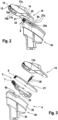
- Figs. 2 and 3 show the cutting head 4 with the comb attachment 10 detached.
- the hair cutting head 4 comprises a cutting head housing 30 made from plastic and a blade unit 5.
- a lower part 34 of said housing 30 is provided as connecting area with the handle 2.
- An upper part 35 of said housing 30 is visible when the cutting head 4 is connected with the handle 2.
- the housing 30 is a hollow part which is closed at its upper end by the stationary blade 6 of the blade unit 5.
- the stationary blade 6 may be made from full metal or plastic with metal teeth. In this case the stationary blade 6 is connected with the cutting head 4 by screws 36 but other connections are possible as well.
- the moveable first blade 7 which cooperates with the cam 32 in order to reciprocate in the direction 8 (see figure 1 ) sideways back and forth relative to the non moveable stationary second blade 6 when in engagement with the eccentric of the motor drive shaft and the motor 3 being operated.
- This movement direction 8 is parallel to a hair cutting edge formed by the tooth tips 6a, 7a of the stationary and / or moveable blade.
- Both blades 6, 7 have a row of hair cutting teeth at its frontal end.
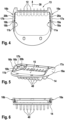
- Figs. 4, 5 and 6 illustrate the comb attachment 10 from different views all with the upper skin contact side shown as the lower side in these Figures.
- This skin contact side 14 is provided with additional multiple protruding hair combing rips 40.
- the comb attachment 10 is formed like a sleeve that is shaped to be sleeved over the cutting head 4 so that the inside coupling side 15 is close or in contact to a skin side 21 of the cutting head 4.
- the comb attachment has a frontal side 13 that is the side which comes first in contact with the hairs to be combed and cut if the device is moved in direction 39 which is an extension of the longitudinal comb teeth 41.
- the comb teeth 41 are aligned in a row and at least partly cover the row of teeth of the blade unit 4. (see fig 1 ).
- lateral sides 16a, 16b Perpendicular to the frontal side 13 with the comb teeth of the comb attachment 10 and laterally to this are provided two lateral sides 16a, 16b with wall portions 18a, 18b. Those wall portions 18a, 18b have insides which face each other and which are each provided with a projection 19a, 19b that serves as the second snap fit connector 11a, 11b.
- the snap fit projections19a, 19b have a substantially U or V shape in cross section.
- longitudinal rip shaped guide rail projections 20a, 20b In alignment with these snap fit projections 19a, 19b are longitudinal rip shaped guide rail projections 20a, 20b also in provided at the inside of the wall portions 18a, 18b.
- each finger gripping area 17a, 17b On each opposite side of the wall portions 18a, 18b, so not the inside but the outside the lateral sides are each provided with a finger gripping area 17a, 17b.
- This finger gripping area's 17a, 17b may be optionally provided with a structure for enhancing the gripping or may be just flat or without gripping texture.
- the lateral sides 16a, 16b and the wall portions 18a, 18b are substantially rigid. As there is no need for a flexing structure at the second snap fit connector 11a, 11b the lateral sides 16a, 16b adds not much thickness so that he comb attachment is less bulky.
- Figs. 7 and 8 illustrate the housing 30 or part of it of the cutting head 4.
- the cutting head 4 has two lateral sides 24a, 25b each with substantially V- or U- shaped projections that form the first snap fit connector 9a, 9b.
- the snap fit connectors 9a, 9b are supported on a longitudinal tongue 26a, 26b which is connected only at it short sides with the rest of the housing 30.
- slots 27a, 27b at both long sides at each of the tongues 26a, 26b so that the tongues are ease to be flexed and bend when a pushing force substantially in the direction of 29 which is perpendicular to the longitudinal extension of the tongues.
- the upper second slot 27a, 27b is formed by a gap between the first, stationary blade 6 and the tongue 26a, 26b of the housing as can be seen in Fig 2 .
- the first snap fit connector 9a, 9b and its supporting tongue 26a, 26b is located recessed relative to the surrounding housing 30 of the cutting head 4. Further the width extension of the second stationary blade 6 larger than the width extension of the first snap fit connector and the tongue supporting same so that these snap fit parts are also recessed relative to the second blade 6. As a consequence, a groove or indentation 25a, 25b is created in which the first snap fit connector slightly protrudes.
- the comb attachment 10 is attached to the cutting head 4 in the direction 21 which corresponds to the movement direction 39 of the device for trimming hair and which is substantially perpendicular to the reciprocation direction of the first blade and or the hair cutting edge formed by the tooth tips of the blade unit 5.
- the inside 15 of the comb attachment 10 slides on the skin surface 21 of the second blade 6.
- the comb is sleeved over the cutting head 4 by slidingly engaging the projections 19a, 19b of the second snap fit connector and the following guide rail projections 20a, 20b along the grooves or indentations 25a, 25b of the cutting head.
- a slight push of in the direction 21 while holding the comb 10 at the gripping area causes the first snap fit connector 9a, 9b to flex away in direction 29 which is perpendicular to the comb attachment sliding direction 21.
- the grip areas of the comb attachment 10 are substantially rigid and the first snap fit connector of the cutting head is able to flex the finger gripping contact force also in direction 29 is not counteracting or preventing the smooth engagement or disengage of the snap fit connection although the first snap fit connector flexes away in the same direction 29 and at the same area 17a, 17b as the finger's grip the comb attachment 10.
Landscapes
- Life Sciences & Earth Sciences (AREA)
- Forests & Forestry (AREA)
- Engineering & Computer Science (AREA)
- Mechanical Engineering (AREA)
- Dry Shavers And Clippers (AREA)
Claims (14)
- Haarentfernungsvorrichtung, insbesondere ein Elektrorasierer oder ein Haarschneider, umfassend:- einen Griff (2), der einen Motor (3) aufweist,- ein Schneidkopfstück (4), das eine Klingeneinheit (5) mit einer ersten und einer zweiten Klinge (6, 7) zum Schneiden von Haaren aufweist, wobei die Klingeneinheit (5) durch den Motor (3) angetrieben wird, so dass sich wenigstens eine der ersten und der zweiten Klinge (6, 7) relativ zu der anderen in einer Hin- und Herbewegungsrichtung (8) hin- und herbewegt, wobei das Schneidkopfstück (4) einen ersten Schnappverbinder (9a, 9b) aufweist und- einen Kammaufsatz (10), der an dem Schneidkopfstück (4) lösbar anbringbar ist, wobei der Kammaufsatz (10) einen zweiten Schnappverbinder (11a, 11b) aufweist, der bereitgestellt ist, um durch eine Schnappverbindung mit dem ersten Schnappverbinder (9a, 9b) in Eingriff zu kommen, zum Anbringen des Kammaufsatzes (10) an dem Schneidkopfstück (4), wobei- der erste Schnappverbinder (9a, 9b) wenigstens eines ist von: ausgebildet in einer Form, um sich zu biegen, aus einem Material hergestellt, um sich zu biegen oder gestützt, um sich zu biegen, so dass der erste Schnappverbinder (9a, 9b) in der Lage ist, sich zu biegen, wenn er mit dem zweiten Schnappverbinder (11a, 11b) in Eingriff gebracht wird, dadurch gekennzeichnet, dass der erste Schnappverbinder (9a, 9b) einteilig ist, der mit einem Schneidkopfstückgehäuse (30) einstückig ist.
- Haarentfernungsvorrichtung nach Anspruch 1, wobei der Kammaufsatz (10) an einer vorderen Seite (13), einer oberen Hautseite (14), einer inneren Haarschneidekopfstückkuppelungsseite (15) und an wenigstens einer lateralen Seite (16a, 16b) mit wenigstens einer Reihe von Kammzähnen (12) versehen ist, wobei die wenigstens eine laterale Seite (16a, 16b) mit einem Wandabschnitt (18a, 18b) versehen ist, der an der Außenseite einen Fingergriffbereich (17a, 17b) und an der Innenseite den zweiten Schnappverbinder (11a, 11b) ausbildet, so dass eine Seite des Wandabschnitts mit dem Fingergriffbereich (17a, 17b) versehen ist und die entgegengesetzte Seite des Wandabschnitts (18a, 18b) mit dem zweiten Schnappverbinder (11a, 11b) versehen ist.
- Haarentfernungsvorrichtung nach Anspruch 2, wobei der Kammaufsatz (10) an einander entgegengesetzten Seiten mit zwei lateralen Seiten (16a, 16b) und an jeder der zwei lateralen Seiten (16a, 16b) mit einem Wandabschnitt (18a, 18b) versehen ist, wobei jeder der Wandabschnitte (18a, 18b) an der Außenseite mit dem Fingergriffbereich (17a, 17b) und auf der entgegengesetzten Innenseite mit dem zweiten Schnappverbinder (11a, 11b) versehen ist.
- Haarentfernungsvorrichtung nach einem der vorstehenden Ansprüche, wobei der zweite Schnappverbinder (11a, 11b) wenigstens eines ist von:
ausgebildet in einer Form, aus einem Material hergestellt oder gestützt, das weniger elastisch ist als der erste Schnappverbinder (9a, 9b). - Haarentfernungsvorrichtung nach einem der Ansprüche 2 oder 3, wobei der eine oder die mehreren zweiten Schnappverbinder (11a, 11b) mit einem Vorsprung (19a, 19b) versehen sind, der von dem Wandabschnitt (18a, 18b) vorsteht, und wobei der Wandabschnitt (18a, 18b) mit einem Führungsschienenvorsprung (20a, 20b) versehen ist, der benachbart zu dem Vorsprung (19a, 19b) des zweiten Schnappverbinders (11a, 11b) und mit diesem ausgerichtet ist, so dass sowohl der Vorsprung (19a, 19b) des zweiten Schnappverbinders (11a, 11b) als auch der Führungsschienenvorsprung (20a, 20b) dazu dienen, den Kammaufsatz (10) während der Anbringung an dem Schneidkopfstück (4) an seinen inneren lateralen Seiten zu führen.
- Haarentfernungsvorrichtung nach einem der vorstehenden Ansprüche,
wobei der Kammaufsatz (10) bereitgestellt ist, um in einer Richtung, die abgewinkelt oder senkrecht zu der Hin- und Herbewegungsrichtung (8) ist, an dem Schneidkopfstück (4) angebracht zu werden. - Haarentfernungsvorrichtung nach einem der vorstehenden Ansprüche,
wobei das Schneidkopfstück (4) mit einer oberen Hautseite (21), wenigstens einer Zahnreihe (6a, 7a) an einem vorderen Ende (23) an jeder der ersten und der zweiten Klinge (6, 7) und wenigstens einer lateralen Seite (24a, 24b) versehen ist, die mit dem ersten Schnappverbinder (9a, 9b) versehen ist. - Haarentfernungsvorrichtung nach dem vorstehenden Anspruch, wobei das Schneidkopfstück (4) mit zwei entgegengesetzten lateralen Seiten (24a, 24b) versehen ist, wobei jede der lateralen Seiten (24a, 24b) mit dem ersten Schnappverbinder (9a, 9b) versehen ist.
- Haarentfernungsvorrichtung nach einem der vorstehenden Ansprüche 7 oder 8, wobei die wenigstens eine laterale Seite (24a, 24b) des Schneidkopfstückes (4) mit einer Vertiefung (25a, 25b) versehen ist und wobei der erste Schnappverbinder (9a, 9b) aus der Vertiefung (25a, 25b) hervorspringt.
- Haarentfernungsvorrichtung nach dem vorstehenden Anspruch, wobei die wenigstens eine Vertiefung (25a, 25b) als eine längs verlaufende Führungsnut zum Führen des zweiten Schnappverbinders (11a, 11b) während des Anbringens des Kammaufsatzes (10) an dem Schneidkopfstück (4) geformt ist.
- Haarentfernungsvorrichtung nach einem der vorstehenden Ansprüche, wobei der erste Schnappverbinder (9a, 9b) durch eine Biegezunge (26a, 26b) gestützt wird.
- Haarentfernungsvorrichtung nach einem der vorstehenden Ansprüche, wobei der erste Schnappverbinder (9a, 9b) von wenigstens einem Schlitz (27a, 27b), insbesondere von zwei entgegengesetzten Schlitzen (27a, 27b), umgeben ist, zum Ermöglichen eines Herunterdrückens oder Bewegens des ersten Schnappverbinders (9a, 9b) während des Anbringens des Kammaufsatzes (10), wenn durch den zweiten Schnappverbinder (11a, 11b) gedrückt.
- Haarentfernungsvorrichtung nach einem der vorstehenden Ansprüche 8 bis 12, wobei sich die zwei ersten Schnappverbinder (9a, 9b) während der Verbindung des Kammaufsatzes (10) aufeinander zu bewegen oder biegen, und mehr bevorzugt die Bewegungs- oder Biegerichtung (29) der zwei ersten Schnappverbinder (9a, 9b) im Wesentlichen der Hin- und Herbewegungsrichtung (8) entspricht.
- Haarentfernungsset, umfassend eine Haarentfernungsvorrichtung nach einem der vorstehenden Ansprüche und einen weiteren Kammaufsatz (10), der an dem Schneidkopfstück (4) lösbar anbringbar ist, wobei der weitere Kammaufsatz den zweiten Schnappverbinder (11a, 11b) aufweist, der bereitgestellt ist, um durch die Schnappverbindung mit dem ersten Schnappverbinder (9a, 9b) in Eingriff zu kommen, zum Anbringen des weiteren Kammaufsatzes an dem Schneidkopfstück (4).
Priority Applications (5)
| Application Number | Priority Date | Filing Date | Title |
|---|---|---|---|
| EP21182056.8A EP4112249B1 (de) | 2021-06-28 | 2021-06-28 | Haarentfernungsvorrichtung |
| US17/850,789 US12240133B2 (en) | 2021-06-28 | 2022-06-27 | Hair removal device |
| PCT/IB2022/055996 WO2023275745A1 (en) | 2021-06-28 | 2022-06-28 | Hair removal device |
| JP2023579743A JP7708897B2 (ja) | 2021-06-28 | 2022-06-28 | 除毛デバイス |
| CN202280044557.8A CN117561147A (zh) | 2021-06-28 | 2022-06-28 | 毛发移除装置 |
Applications Claiming Priority (1)
| Application Number | Priority Date | Filing Date | Title |
|---|---|---|---|
| EP21182056.8A EP4112249B1 (de) | 2021-06-28 | 2021-06-28 | Haarentfernungsvorrichtung |
Publications (2)
| Publication Number | Publication Date |
|---|---|
| EP4112249A1 EP4112249A1 (de) | 2023-01-04 |
| EP4112249B1 true EP4112249B1 (de) | 2025-03-19 |
Family
ID=76695581
Family Applications (1)
| Application Number | Title | Priority Date | Filing Date |
|---|---|---|---|
| EP21182056.8A Active EP4112249B1 (de) | 2021-06-28 | 2021-06-28 | Haarentfernungsvorrichtung |
Country Status (5)
| Country | Link |
|---|---|
| US (1) | US12240133B2 (de) |
| EP (1) | EP4112249B1 (de) |
| JP (1) | JP7708897B2 (de) |
| CN (1) | CN117561147A (de) |
| WO (1) | WO2023275745A1 (de) |
Families Citing this family (9)
| Publication number | Priority date | Publication date | Assignee | Title |
|---|---|---|---|---|
| US12403619B2 (en) * | 2008-11-24 | 2025-09-02 | Lonnie Andrew Holmes | Hair clippers with flexing electrically adjustable blades |
| USD922684S1 (en) * | 2019-01-24 | 2021-06-15 | Braun Gmbh | Part of a hair removal device |
| CN112112873B (zh) * | 2020-10-28 | 2025-05-30 | 湖北亿纬动力有限公司 | 一种连接铆钉及电池模组 |
| EP4112245B1 (de) * | 2021-06-28 | 2025-10-22 | Braun GmbH | Haarschneidekit |
| USD991559S1 (en) * | 2022-03-09 | 2023-07-04 | Shenzhen Early Century Technology Co., Ltd. | Rotary guide comb |
| USD1045226S1 (en) * | 2022-07-27 | 2024-10-01 | E. Mishan & Sons, Inc. | Vacuum shaver |
| USD1035150S1 (en) * | 2023-01-17 | 2024-07-09 | Ningbo VGR Electric Appliance Co., Ltd. | Hair clipper |
| USD1035151S1 (en) * | 2022-12-21 | 2024-07-09 | Ningbo VGR Electric Appliance Co., Ltd. | Hair clipper |
| USD1106582S1 (en) * | 2023-11-07 | 2025-12-16 | Wenzhou Ante Electrical Appliance Co., Ltd. | Hair clipper |
Family Cites Families (15)
| Publication number | Priority date | Publication date | Assignee | Title |
|---|---|---|---|---|
| US4622745A (en) * | 1984-09-28 | 1986-11-18 | Wahl Clipper Corporation | Hair trimming apparatus |
| DE3623591A1 (de) * | 1986-07-12 | 1988-01-21 | Moser Gmbh Kuno | Haarschneidemaschine mit schnittlaengenverstellung |
| JP2544756B2 (ja) * | 1987-08-13 | 1996-10-16 | 松下電工株式会社 | ヘアカッタ― |
| DE4141582C2 (de) * | 1991-12-17 | 1999-05-20 | Braun Gmbh | Elektrische Haarschneidemaschine |
| US6807736B2 (en) * | 2001-09-25 | 2004-10-26 | Wahl Clipper Corporation | Color-coded attachment comb key for hair clipper |
| JP4466077B2 (ja) * | 2003-12-26 | 2010-05-26 | パナソニック電工株式会社 | ヘアカッター |
| JP4103873B2 (ja) * | 2004-09-01 | 2008-06-18 | 松下電工株式会社 | ヘアカッターのコーム振動防止構造 |
| EP2322328A1 (de) * | 2009-11-17 | 2011-05-18 | Koninklijke Philips Electronics N.V. | Haarschneidegerät mit Kammeinheitserkennung |
| JP5731725B2 (ja) * | 2012-12-10 | 2015-06-10 | コーニンクレッカ フィリップス エヌ ヴェ | ヘアートリム装置 |
| RU2682358C2 (ru) * | 2015-02-26 | 2019-03-19 | Конинклейке Филипс Н.В. | Гребенчатая насадка и прибор для стрижки волос |
| EP3331670B1 (de) * | 2015-08-04 | 2020-02-26 | Koninklijke Philips N.V. | Haarbehälter und kit für eine haarschneidevorrichtung |
| EP3402637B1 (de) * | 2016-01-12 | 2021-11-03 | Koninklijke Philips N.V. | Längenanpassungsvorrichtung für ein haarschneidegerät |
| CN206277422U (zh) * | 2016-11-16 | 2017-06-27 | 杨海江 | 一种理发剪限位梳调节结构 |
| US12233563B2 (en) * | 2022-08-16 | 2025-02-25 | Wahl Clipper Corporation | Hair clipper attachment comb with enhanced hair flow geometry |
| EP4331788A1 (de) * | 2022-08-30 | 2024-03-06 | Braun GmbH | Elektrische haarentfernungsvorrichtung, kit und aufsatz |
-
2021
- 2021-06-28 EP EP21182056.8A patent/EP4112249B1/de active Active
-
2022
- 2022-06-27 US US17/850,789 patent/US12240133B2/en active Active
- 2022-06-28 JP JP2023579743A patent/JP7708897B2/ja active Active
- 2022-06-28 CN CN202280044557.8A patent/CN117561147A/zh active Pending
- 2022-06-28 WO PCT/IB2022/055996 patent/WO2023275745A1/en not_active Ceased
Also Published As
| Publication number | Publication date |
|---|---|
| JP2024523590A (ja) | 2024-06-28 |
| US20220410420A1 (en) | 2022-12-29 |
| JP7708897B2 (ja) | 2025-07-15 |
| EP4112249A1 (de) | 2023-01-04 |
| US12240133B2 (en) | 2025-03-04 |
| CN117561147A (zh) | 2024-02-13 |
| WO2023275745A1 (en) | 2023-01-05 |
Similar Documents
| Publication | Publication Date | Title |
|---|---|---|
| EP4112249B1 (de) | Haarentfernungsvorrichtung | |
| CN108656157B (zh) | 用于毛发切割器具的间隔梳子装置、切割头和毛发切割器具 | |
| CN206011158U (zh) | 可释放附件梳及切割头 | |
| AU2015246185B2 (en) | Blade set, hair cutting appliance, and related manufacturing method | |
| KR100803865B1 (ko) | 이발기 | |
| CN205735054U (zh) | 切割头和毛发切割器具 | |
| US10226873B2 (en) | Hair cutting appliance, receptacle and connector plug | |
| CN204658474U (zh) | 剪发器具和刀片组 | |
| JP3601092B2 (ja) | ヘアーカッター | |
| CN109079862B (zh) | 毛发切割系统和附件 | |
| EP0885094A1 (de) | Haarschneidesystem mit einer haarschneidevorrichtung, die einen einstellknopf und einen einlaufknopf hat | |
| EP2465652B1 (de) | Haarschneider | |
| EP3785869A1 (de) | Elektrischer haarschneider | |
| US4233733A (en) | Electric shaver | |
| EP0886563A1 (de) | Haarschneidesystem mit einer haarschneidevorrichtung und einer kammvorrichtung, die an der haarschneidevorrichtung befestigt werden kann und die zwei federbelastete kammabschnitte hat | |
| US5123159A (en) | Hair clipper | |
| CN101489737B (zh) | 毛发修剪器 | |
| CN115139344A (zh) | 刀片单元和电动剃刀 | |
| US4131995A (en) | Smoothing comb for a hair trimmer | |
| JP5879531B2 (ja) | 電気かみそり | |
| JPH09253353A (ja) | 往復式電気かみそり | |
| JP2002273072A (ja) | 電気かみそり | |
| JP5887511B2 (ja) | 電気かみそり | |
| JP2013126439A (ja) | 電気かみそり | |
| KR20090077330A (ko) | 전동 이발기 |
Legal Events
| Date | Code | Title | Description |
|---|---|---|---|
| PUAI | Public reference made under article 153(3) epc to a published international application that has entered the european phase |
Free format text: ORIGINAL CODE: 0009012 |
|
| STAA | Information on the status of an ep patent application or granted ep patent |
Free format text: STATUS: THE APPLICATION HAS BEEN PUBLISHED |
|
| AK | Designated contracting states |
Kind code of ref document: A1 Designated state(s): AL AT BE BG CH CY CZ DE DK EE ES FI FR GB GR HR HU IE IS IT LI LT LU LV MC MK MT NL NO PL PT RO RS SE SI SK SM TR |
|
| P01 | Opt-out of the competence of the unified patent court (upc) registered |
Effective date: 20230430 |
|
| STAA | Information on the status of an ep patent application or granted ep patent |
Free format text: STATUS: REQUEST FOR EXAMINATION WAS MADE |
|
| 17P | Request for examination filed |
Effective date: 20230928 |
|
| RBV | Designated contracting states (corrected) |
Designated state(s): AL AT BE BG CH CY CZ DE DK EE ES FI FR GB GR HR HU IE IS IT LI LT LU LV MC MK MT NL NO PL PT RO RS SE SI SK SM TR |
|
| GRAP | Despatch of communication of intention to grant a patent |
Free format text: ORIGINAL CODE: EPIDOSNIGR1 |
|
| STAA | Information on the status of an ep patent application or granted ep patent |
Free format text: STATUS: GRANT OF PATENT IS INTENDED |
|
| INTG | Intention to grant announced |
Effective date: 20241008 |
|
| GRAS | Grant fee paid |
Free format text: ORIGINAL CODE: EPIDOSNIGR3 |
|
| GRAA | (expected) grant |
Free format text: ORIGINAL CODE: 0009210 |
|
| STAA | Information on the status of an ep patent application or granted ep patent |
Free format text: STATUS: THE PATENT HAS BEEN GRANTED |
|
| AK | Designated contracting states |
Kind code of ref document: B1 Designated state(s): AL AT BE BG CH CY CZ DE DK EE ES FI FR GB GR HR HU IE IS IT LI LT LU LV MC MK MT NL NO PL PT RO RS SE SI SK SM TR |
|
| REG | Reference to a national code |
Ref country code: GB Ref legal event code: FG4D |
|
| REG | Reference to a national code |
Ref country code: CH Ref legal event code: EP |
|
| REG | Reference to a national code |
Ref country code: IE Ref legal event code: FG4D |
|
| REG | Reference to a national code |
Ref country code: DE Ref legal event code: R096 Ref document number: 602021027710 Country of ref document: DE |
|
| REG | Reference to a national code |
Ref country code: NL Ref legal event code: FP |
|
| PGFP | Annual fee paid to national office [announced via postgrant information from national office to epo] |
Ref country code: NL Payment date: 20250516 Year of fee payment: 5 |
|
| PG25 | Lapsed in a contracting state [announced via postgrant information from national office to epo] |
Ref country code: RS Free format text: LAPSE BECAUSE OF FAILURE TO SUBMIT A TRANSLATION OF THE DESCRIPTION OR TO PAY THE FEE WITHIN THE PRESCRIBED TIME-LIMIT Effective date: 20250619 |
|
| PG25 | Lapsed in a contracting state [announced via postgrant information from national office to epo] |
Ref country code: FI Free format text: LAPSE BECAUSE OF FAILURE TO SUBMIT A TRANSLATION OF THE DESCRIPTION OR TO PAY THE FEE WITHIN THE PRESCRIBED TIME-LIMIT Effective date: 20250319 |
|
| PGFP | Annual fee paid to national office [announced via postgrant information from national office to epo] |
Ref country code: DE Payment date: 20250507 Year of fee payment: 5 |
|
| PGFP | Annual fee paid to national office [announced via postgrant information from national office to epo] |
Ref country code: GB Payment date: 20250508 Year of fee payment: 5 |
|
| REG | Reference to a national code |
Ref country code: LT Ref legal event code: MG9D |
|
| PG25 | Lapsed in a contracting state [announced via postgrant information from national office to epo] |
Ref country code: NO Free format text: LAPSE BECAUSE OF FAILURE TO SUBMIT A TRANSLATION OF THE DESCRIPTION OR TO PAY THE FEE WITHIN THE PRESCRIBED TIME-LIMIT Effective date: 20250619 |
|
| PG25 | Lapsed in a contracting state [announced via postgrant information from national office to epo] |
Ref country code: HR Free format text: LAPSE BECAUSE OF FAILURE TO SUBMIT A TRANSLATION OF THE DESCRIPTION OR TO PAY THE FEE WITHIN THE PRESCRIBED TIME-LIMIT Effective date: 20250319 |
|
| PG25 | Lapsed in a contracting state [announced via postgrant information from national office to epo] |
Ref country code: LV Free format text: LAPSE BECAUSE OF FAILURE TO SUBMIT A TRANSLATION OF THE DESCRIPTION OR TO PAY THE FEE WITHIN THE PRESCRIBED TIME-LIMIT Effective date: 20250319 |
|
| PGFP | Annual fee paid to national office [announced via postgrant information from national office to epo] |
Ref country code: FR Payment date: 20250508 Year of fee payment: 5 |
|
| PG25 | Lapsed in a contracting state [announced via postgrant information from national office to epo] |
Ref country code: GR Free format text: LAPSE BECAUSE OF FAILURE TO SUBMIT A TRANSLATION OF THE DESCRIPTION OR TO PAY THE FEE WITHIN THE PRESCRIBED TIME-LIMIT Effective date: 20250620 Ref country code: BG Free format text: LAPSE BECAUSE OF FAILURE TO SUBMIT A TRANSLATION OF THE DESCRIPTION OR TO PAY THE FEE WITHIN THE PRESCRIBED TIME-LIMIT Effective date: 20250319 |
|
| REG | Reference to a national code |
Ref country code: AT Ref legal event code: MK05 Ref document number: 1776606 Country of ref document: AT Kind code of ref document: T Effective date: 20250319 |
|
| PG25 | Lapsed in a contracting state [announced via postgrant information from national office to epo] |
Ref country code: SE Free format text: LAPSE BECAUSE OF FAILURE TO SUBMIT A TRANSLATION OF THE DESCRIPTION OR TO PAY THE FEE WITHIN THE PRESCRIBED TIME-LIMIT Effective date: 20250319 |
|
| PG25 | Lapsed in a contracting state [announced via postgrant information from national office to epo] |
Ref country code: SM Free format text: LAPSE BECAUSE OF FAILURE TO SUBMIT A TRANSLATION OF THE DESCRIPTION OR TO PAY THE FEE WITHIN THE PRESCRIBED TIME-LIMIT Effective date: 20250319 |
|
| PG25 | Lapsed in a contracting state [announced via postgrant information from national office to epo] |
Ref country code: ES Free format text: LAPSE BECAUSE OF FAILURE TO SUBMIT A TRANSLATION OF THE DESCRIPTION OR TO PAY THE FEE WITHIN THE PRESCRIBED TIME-LIMIT Effective date: 20250319 Ref country code: PT Free format text: LAPSE BECAUSE OF FAILURE TO SUBMIT A TRANSLATION OF THE DESCRIPTION OR TO PAY THE FEE WITHIN THE PRESCRIBED TIME-LIMIT Effective date: 20250721 |
|
| PG25 | Lapsed in a contracting state [announced via postgrant information from national office to epo] |
Ref country code: IT Free format text: LAPSE BECAUSE OF FAILURE TO SUBMIT A TRANSLATION OF THE DESCRIPTION OR TO PAY THE FEE WITHIN THE PRESCRIBED TIME-LIMIT Effective date: 20250319 Ref country code: PL Free format text: LAPSE BECAUSE OF FAILURE TO SUBMIT A TRANSLATION OF THE DESCRIPTION OR TO PAY THE FEE WITHIN THE PRESCRIBED TIME-LIMIT Effective date: 20250319 |
|
| PG25 | Lapsed in a contracting state [announced via postgrant information from national office to epo] |
Ref country code: AT Free format text: LAPSE BECAUSE OF FAILURE TO SUBMIT A TRANSLATION OF THE DESCRIPTION OR TO PAY THE FEE WITHIN THE PRESCRIBED TIME-LIMIT Effective date: 20250319 |
|
| PG25 | Lapsed in a contracting state [announced via postgrant information from national office to epo] |
Ref country code: CZ Free format text: LAPSE BECAUSE OF FAILURE TO SUBMIT A TRANSLATION OF THE DESCRIPTION OR TO PAY THE FEE WITHIN THE PRESCRIBED TIME-LIMIT Effective date: 20250319 Ref country code: EE Free format text: LAPSE BECAUSE OF FAILURE TO SUBMIT A TRANSLATION OF THE DESCRIPTION OR TO PAY THE FEE WITHIN THE PRESCRIBED TIME-LIMIT Effective date: 20250319 |
|
| PG25 | Lapsed in a contracting state [announced via postgrant information from national office to epo] |
Ref country code: RO Free format text: LAPSE BECAUSE OF FAILURE TO SUBMIT A TRANSLATION OF THE DESCRIPTION OR TO PAY THE FEE WITHIN THE PRESCRIBED TIME-LIMIT Effective date: 20250319 |
|
| PG25 | Lapsed in a contracting state [announced via postgrant information from national office to epo] |
Ref country code: SK Free format text: LAPSE BECAUSE OF FAILURE TO SUBMIT A TRANSLATION OF THE DESCRIPTION OR TO PAY THE FEE WITHIN THE PRESCRIBED TIME-LIMIT Effective date: 20250319 |
|
| PG25 | Lapsed in a contracting state [announced via postgrant information from national office to epo] |
Ref country code: IS Free format text: LAPSE BECAUSE OF FAILURE TO SUBMIT A TRANSLATION OF THE DESCRIPTION OR TO PAY THE FEE WITHIN THE PRESCRIBED TIME-LIMIT Effective date: 20250719 |
|
| REG | Reference to a national code |
Ref country code: DE Ref legal event code: R097 Ref document number: 602021027710 Country of ref document: DE |
|
| PG25 | Lapsed in a contracting state [announced via postgrant information from national office to epo] |
Ref country code: DK Free format text: LAPSE BECAUSE OF FAILURE TO SUBMIT A TRANSLATION OF THE DESCRIPTION OR TO PAY THE FEE WITHIN THE PRESCRIBED TIME-LIMIT Effective date: 20250319 |
|
| PLBE | No opposition filed within time limit |
Free format text: ORIGINAL CODE: 0009261 |
|
| STAA | Information on the status of an ep patent application or granted ep patent |
Free format text: STATUS: NO OPPOSITION FILED WITHIN TIME LIMIT |
|
| REG | Reference to a national code |
Ref country code: CH Ref legal event code: H13 Free format text: ST27 STATUS EVENT CODE: U-0-0-H10-H13 (AS PROVIDED BY THE NATIONAL OFFICE) Effective date: 20260127 |
|
| REG | Reference to a national code |
Ref country code: CH Ref legal event code: L10 Free format text: ST27 STATUS EVENT CODE: U-0-0-L10-L00 (AS PROVIDED BY THE NATIONAL OFFICE) Effective date: 20260128 |
|
| PG25 | Lapsed in a contracting state [announced via postgrant information from national office to epo] |
Ref country code: MC Free format text: LAPSE BECAUSE OF FAILURE TO SUBMIT A TRANSLATION OF THE DESCRIPTION OR TO PAY THE FEE WITHIN THE PRESCRIBED TIME-LIMIT Effective date: 20250319 |
|
| PG25 | Lapsed in a contracting state [announced via postgrant information from national office to epo] |
Ref country code: LU Free format text: LAPSE BECAUSE OF NON-PAYMENT OF DUE FEES Effective date: 20250628 |
|
| 26N | No opposition filed |
Effective date: 20251222 |
|
| REG | Reference to a national code |
Ref country code: BE Ref legal event code: MM Effective date: 20250630 |
|
| PG25 | Lapsed in a contracting state [announced via postgrant information from national office to epo] |
Ref country code: IE Free format text: LAPSE BECAUSE OF NON-PAYMENT OF DUE FEES Effective date: 20250628 |
|
| PG25 | Lapsed in a contracting state [announced via postgrant information from national office to epo] |
Ref country code: BE Free format text: LAPSE BECAUSE OF NON-PAYMENT OF DUE FEES Effective date: 20250630 |