EP4112380A1 - Verfahren und vorrichtung zur steuerung der beleuchtung eines fahrzeugs - Google Patents
Verfahren und vorrichtung zur steuerung der beleuchtung eines fahrzeugs Download PDFInfo
- Publication number
- EP4112380A1 EP4112380A1 EP20927524.7A EP20927524A EP4112380A1 EP 4112380 A1 EP4112380 A1 EP 4112380A1 EP 20927524 A EP20927524 A EP 20927524A EP 4112380 A1 EP4112380 A1 EP 4112380A1
- Authority
- EP
- European Patent Office
- Prior art keywords
- vehicle
- target
- turn
- illuminate
- message
- Prior art date
- Legal status (The legal status is an assumption and is not a legal conclusion. Google has not performed a legal analysis and makes no representation as to the accuracy of the status listed.)
- Withdrawn
Links
Images




Classifications
-
- B—PERFORMING OPERATIONS; TRANSPORTING
- B60—VEHICLES IN GENERAL
- B60Q—ARRANGEMENT OF SIGNALLING OR LIGHTING DEVICES, THE MOUNTING OR SUPPORTING THEREOF OR CIRCUITS THEREFOR, FOR VEHICLES IN GENERAL
- B60Q1/00—Arrangement of optical signalling or lighting devices, the mounting or supporting thereof or circuits therefor
- B60Q1/02—Arrangement of optical signalling or lighting devices, the mounting or supporting thereof or circuits therefor the devices being primarily intended to illuminate the way ahead or to illuminate other areas of way or environments
- B60Q1/04—Arrangement of optical signalling or lighting devices, the mounting or supporting thereof or circuits therefor the devices being primarily intended to illuminate the way ahead or to illuminate other areas of way or environments the devices being headlights
- B60Q1/14—Arrangement of optical signalling or lighting devices, the mounting or supporting thereof or circuits therefor the devices being primarily intended to illuminate the way ahead or to illuminate other areas of way or environments the devices being headlights having dimming means
- B60Q1/1415—Dimming circuits
- B60Q1/1423—Automatic dimming circuits, i.e. switching between high beam and low beam due to change of ambient light or light level in road traffic
-
- B—PERFORMING OPERATIONS; TRANSPORTING
- B60—VEHICLES IN GENERAL
- B60Q—ARRANGEMENT OF SIGNALLING OR LIGHTING DEVICES, THE MOUNTING OR SUPPORTING THEREOF OR CIRCUITS THEREFOR, FOR VEHICLES IN GENERAL
- B60Q1/00—Arrangement of optical signalling or lighting devices, the mounting or supporting thereof or circuits therefor
- B60Q1/02—Arrangement of optical signalling or lighting devices, the mounting or supporting thereof or circuits therefor the devices being primarily intended to illuminate the way ahead or to illuminate other areas of way or environments
- B60Q1/04—Arrangement of optical signalling or lighting devices, the mounting or supporting thereof or circuits therefor the devices being primarily intended to illuminate the way ahead or to illuminate other areas of way or environments the devices being headlights
- B60Q1/06—Arrangement of optical signalling or lighting devices, the mounting or supporting thereof or circuits therefor the devices being primarily intended to illuminate the way ahead or to illuminate other areas of way or environments the devices being headlights adjustable, e.g. remotely-controlled from inside vehicle
- B60Q1/08—Arrangement of optical signalling or lighting devices, the mounting or supporting thereof or circuits therefor the devices being primarily intended to illuminate the way ahead or to illuminate other areas of way or environments the devices being headlights adjustable, e.g. remotely-controlled from inside vehicle automatically
-
- B—PERFORMING OPERATIONS; TRANSPORTING
- B60—VEHICLES IN GENERAL
- B60Q—ARRANGEMENT OF SIGNALLING OR LIGHTING DEVICES, THE MOUNTING OR SUPPORTING THEREOF OR CIRCUITS THEREFOR, FOR VEHICLES IN GENERAL
- B60Q1/00—Arrangement of optical signalling or lighting devices, the mounting or supporting thereof or circuits therefor
- B60Q1/02—Arrangement of optical signalling or lighting devices, the mounting or supporting thereof or circuits therefor the devices being primarily intended to illuminate the way ahead or to illuminate other areas of way or environments
- B60Q1/04—Arrangement of optical signalling or lighting devices, the mounting or supporting thereof or circuits therefor the devices being primarily intended to illuminate the way ahead or to illuminate other areas of way or environments the devices being headlights
- B60Q1/06—Arrangement of optical signalling or lighting devices, the mounting or supporting thereof or circuits therefor the devices being primarily intended to illuminate the way ahead or to illuminate other areas of way or environments the devices being headlights adjustable, e.g. remotely-controlled from inside vehicle
- B60Q1/08—Arrangement of optical signalling or lighting devices, the mounting or supporting thereof or circuits therefor the devices being primarily intended to illuminate the way ahead or to illuminate other areas of way or environments the devices being headlights adjustable, e.g. remotely-controlled from inside vehicle automatically
- B60Q1/085—Arrangement of optical signalling or lighting devices, the mounting or supporting thereof or circuits therefor the devices being primarily intended to illuminate the way ahead or to illuminate other areas of way or environments the devices being headlights adjustable, e.g. remotely-controlled from inside vehicle automatically due to special conditions, e.g. adverse weather, type of road, badly illuminated road signs or potential dangers
-
- B—PERFORMING OPERATIONS; TRANSPORTING
- B60—VEHICLES IN GENERAL
- B60Q—ARRANGEMENT OF SIGNALLING OR LIGHTING DEVICES, THE MOUNTING OR SUPPORTING THEREOF OR CIRCUITS THEREFOR, FOR VEHICLES IN GENERAL
- B60Q1/00—Arrangement of optical signalling or lighting devices, the mounting or supporting thereof or circuits therefor
- B60Q1/02—Arrangement of optical signalling or lighting devices, the mounting or supporting thereof or circuits therefor the devices being primarily intended to illuminate the way ahead or to illuminate other areas of way or environments
- B60Q1/24—Arrangement of optical signalling or lighting devices, the mounting or supporting thereof or circuits therefor the devices being primarily intended to illuminate the way ahead or to illuminate other areas of way or environments for lighting other areas than only the way ahead
-
- H—ELECTRICITY
- H04—ELECTRIC COMMUNICATION TECHNIQUE
- H04W—WIRELESS COMMUNICATION NETWORKS
- H04W4/00—Services specially adapted for wireless communication networks; Facilities therefor
- H04W4/30—Services specially adapted for particular environments, situations or purposes
- H04W4/40—Services specially adapted for particular environments, situations or purposes for vehicles, e.g. vehicle-to-pedestrians [V2P]
- H04W4/44—Services specially adapted for particular environments, situations or purposes for vehicles, e.g. vehicle-to-pedestrians [V2P] for communication between vehicles and infrastructures, e.g. vehicle-to-cloud [V2C] or vehicle-to-home [V2H]
-
- H—ELECTRICITY
- H05—ELECTRIC TECHNIQUES NOT OTHERWISE PROVIDED FOR
- H05B—ELECTRIC HEATING; ELECTRIC LIGHT SOURCES NOT OTHERWISE PROVIDED FOR; CIRCUIT ARRANGEMENTS FOR ELECTRIC LIGHT SOURCES, IN GENERAL
- H05B47/00—Circuit arrangements for operating light sources in general, i.e. where the type of light source is not relevant
- H05B47/10—Controlling the light source
- H05B47/105—Controlling the light source in response to determined parameters
-
- B—PERFORMING OPERATIONS; TRANSPORTING
- B60—VEHICLES IN GENERAL
- B60Q—ARRANGEMENT OF SIGNALLING OR LIGHTING DEVICES, THE MOUNTING OR SUPPORTING THEREOF OR CIRCUITS THEREFOR, FOR VEHICLES IN GENERAL
- B60Q1/00—Arrangement of optical signalling or lighting devices, the mounting or supporting thereof or circuits therefor
- B60Q1/02—Arrangement of optical signalling or lighting devices, the mounting or supporting thereof or circuits therefor the devices being primarily intended to illuminate the way ahead or to illuminate other areas of way or environments
- B60Q1/04—Arrangement of optical signalling or lighting devices, the mounting or supporting thereof or circuits therefor the devices being primarily intended to illuminate the way ahead or to illuminate other areas of way or environments the devices being headlights
- B60Q1/18—Arrangement of optical signalling or lighting devices, the mounting or supporting thereof or circuits therefor the devices being primarily intended to illuminate the way ahead or to illuminate other areas of way or environments the devices being headlights being additional front lights
-
- B—PERFORMING OPERATIONS; TRANSPORTING
- B60—VEHICLES IN GENERAL
- B60Q—ARRANGEMENT OF SIGNALLING OR LIGHTING DEVICES, THE MOUNTING OR SUPPORTING THEREOF OR CIRCUITS THEREFOR, FOR VEHICLES IN GENERAL
- B60Q2300/00—Indexing codes for automatically adjustable headlamps or automatically dimmable headlamps
- B60Q2300/05—Special features for controlling or switching of the light beam
- B60Q2300/054—Variable non-standard intensity, i.e. emission of various beam intensities different from standard intensities, e.g. continuous or stepped transitions of intensity
-
- B—PERFORMING OPERATIONS; TRANSPORTING
- B60—VEHICLES IN GENERAL
- B60Q—ARRANGEMENT OF SIGNALLING OR LIGHTING DEVICES, THE MOUNTING OR SUPPORTING THEREOF OR CIRCUITS THEREFOR, FOR VEHICLES IN GENERAL
- B60Q2300/00—Indexing codes for automatically adjustable headlamps or automatically dimmable headlamps
- B60Q2300/30—Indexing codes relating to the vehicle environment
- B60Q2300/32—Road surface or travel path
-
- B—PERFORMING OPERATIONS; TRANSPORTING
- B60—VEHICLES IN GENERAL
- B60Q—ARRANGEMENT OF SIGNALLING OR LIGHTING DEVICES, THE MOUNTING OR SUPPORTING THEREOF OR CIRCUITS THEREFOR, FOR VEHICLES IN GENERAL
- B60Q2300/00—Indexing codes for automatically adjustable headlamps or automatically dimmable headlamps
- B60Q2300/30—Indexing codes relating to the vehicle environment
- B60Q2300/32—Road surface or travel path
- B60Q2300/322—Road curvature
-
- B—PERFORMING OPERATIONS; TRANSPORTING
- B60—VEHICLES IN GENERAL
- B60Q—ARRANGEMENT OF SIGNALLING OR LIGHTING DEVICES, THE MOUNTING OR SUPPORTING THEREOF OR CIRCUITS THEREFOR, FOR VEHICLES IN GENERAL
- B60Q2300/00—Indexing codes for automatically adjustable headlamps or automatically dimmable headlamps
- B60Q2300/40—Indexing codes relating to other road users or special conditions
- B60Q2300/45—Special conditions, e.g. pedestrians, road signs or potential dangers
-
- B—PERFORMING OPERATIONS; TRANSPORTING
- B60—VEHICLES IN GENERAL
- B60Q—ARRANGEMENT OF SIGNALLING OR LIGHTING DEVICES, THE MOUNTING OR SUPPORTING THEREOF OR CIRCUITS THEREFOR, FOR VEHICLES IN GENERAL
- B60Q2300/00—Indexing codes for automatically adjustable headlamps or automatically dimmable headlamps
- B60Q2300/40—Indexing codes relating to other road users or special conditions
- B60Q2300/47—Direct command from other road users, i.e. the command for switching or changing the beam is sent by other vehicles or road devices
-
- B—PERFORMING OPERATIONS; TRANSPORTING
- B60—VEHICLES IN GENERAL
- B60Q—ARRANGEMENT OF SIGNALLING OR LIGHTING DEVICES, THE MOUNTING OR SUPPORTING THEREOF OR CIRCUITS THEREFOR, FOR VEHICLES IN GENERAL
- B60Q2900/00—Features of lamps not covered by other groups in B60Q
- B60Q2900/30—Lamps commanded by wireless transmissions
-
- Y—GENERAL TAGGING OF NEW TECHNOLOGICAL DEVELOPMENTS; GENERAL TAGGING OF CROSS-SECTIONAL TECHNOLOGIES SPANNING OVER SEVERAL SECTIONS OF THE IPC; TECHNICAL SUBJECTS COVERED BY FORMER USPC CROSS-REFERENCE ART COLLECTIONS [XRACs] AND DIGESTS
- Y02—TECHNOLOGIES OR APPLICATIONS FOR MITIGATION OR ADAPTATION AGAINST CLIMATE CHANGE
- Y02B—CLIMATE CHANGE MITIGATION TECHNOLOGIES RELATED TO BUILDINGS, e.g. HOUSING, HOUSE APPLIANCES OR RELATED END-USER APPLICATIONS
- Y02B20/00—Energy efficient lighting technologies, e.g. halogen lamps or gas discharge lamps
- Y02B20/40—Control techniques providing energy savings, e.g. smart controller or presence detection
Definitions
- This application relates to the field of connected vehicles and intelligent driving technologies, and in particular, to a vehicle lighting control method and a device.
- an area having a safety risk in front of the vehicle may not be illuminated due to a limited illumination range of a vehicle lamp.
- the area is referred to as a visual blind area. Illuminating the area in advance can help a driver make a safer driving decision, so that driving safety is improved.
- the conventional technology provides two lighting systems for a curve at night: a light source supplementing curve lighting system and an adaptive front-lighting system (adaptive front-lighting system, AFS for short).
- a supplementary light source such as a corner lamp or a static curve low beam lamp needs to be additionally disposed on the vehicle.
- the driver may turn on a corresponding supplementary light source by rotating a steering wheel, to illuminate the blind area in the curve.
- the AFS may adaptively rotate a corresponding angle based on a steering lock angle of the vehicle or a trajectory of a gravity center of the vehicle, to illuminate the blind area in the curve.
- both of the foregoing two curve lighting systems are triggered to be enabled by rotating the steering wheel after the driver autonomously determines that there is a curve in front of the vehicle.
- the vehicle has entered the curve.
- the driver may need to observe a road condition of the blind area in the curve before the vehicle enters the curve, to provide reference for a steering operation of the driver. It is clear that lighting operations of the foregoing two curve lighting systems are delayed, and neither of the foregoing two curve lighting systems is applicable to lighting of another type of visual blind area. As a result, safety of driving the vehicle is low.
- Embodiments of this application provide a vehicle lighting control method and a device, to resolve a problem in the conventional technology that driving safety is low because it depends on a driver to actively trigger lighting of a visual blind area.
- a vehicle lighting control method is provided and applied to a vehicle.
- the method includes: receiving a first message sent by a first roadside communications device, where the first message is used to prompt the vehicle to illuminate a first target, and the first target is near a travel path that the vehicle is to pass through; and adjusting the vehicle into a first lighting mode in advance based on the first message before the vehicle passes the first target, to illuminate the first target, where the passing the first target means reaching the first target, or means that the vehicle reaches a location closest to the first target on the travel path.
- the roadside communications device includes but is not limited to a base station, a roadside unit RSU, and another vehicle or communications device on a road on which the vehicle travels.
- the first target includes but is not limited to a curve, a construction site, a roadblock, or a blind area of regular lighting of the vehicle.
- the foregoing vehicle lighting control method may be applied to the vehicle. After the first message sent by the first roadside communications device is received, before the vehicle passes the first target, the vehicle is adjusted into the first lighting mode in advance based on the first message, to illuminate the first target. In this way, the vehicle can automatically adjust a lighting mode to illuminate a visual blind area in advance. Because the foregoing method does not rely on active triggering of a driver, a problem of a delayed lighting operation in the conventional technology can be avoided. In addition, the foregoing method is more than applicable to an illumination scenario of a visual blind area in a curve and is applicable to an illumination scenario of a roadside blind area. This greatly improves driving safety.
- the first message includes at least one parameter
- the adjusting the vehicle into a first lighting mode in advance based on the first message before the vehicle passes the first target, to illuminate the first target includes:
- the at least one parameter includes but is not limited to a type of a first location, a geographical location of the first location, a moving speed at the first location, or the first timing advance.
- the first message includes at least one parameter
- the adjusting the vehicle into a first lighting mode in advance based on the first message before the vehicle passes the first target, to illuminate the first target includes:
- the at least one parameter includes but is not limited to a type of a first location, a geographical location of the first location, a moving speed at the first location, a first timing advance, or a first distance.
- the first message includes at least one parameter
- the adjusting the vehicle into a first lighting mode in advance based on the first message before the vehicle passes the first target, to illuminate the first target includes:
- the at least one parameter includes but is not limited to a type of a first location, a geographical location of the first location, a moving speed at the first location, or a first timing advance.
- the first message includes a first turn-on moment
- the adjusting the vehicle into a first lighting mode in advance based on the first message before the vehicle passes the first target, to illuminate the first target includes: adjusting the vehicle into the first lighting mode at the first turn-on moment.
- the first message includes a first turn-on location
- the adjusting the vehicle into a first lighting mode in advance based on the first message before the vehicle passes the first target, to illuminate the first target includes: adjusting the vehicle into the first lighting mode when the vehicle arrives at the first turn-on location, to illuminate the first target.
- the first message includes a first distance
- the adjusting the vehicle into a first lighting mode in advance based on the first message before the vehicle passes the first target, to illuminate the first target includes: adjusting the vehicle into the first lighting mode when the vehicle arrives at a location that is the first distance from the first target, to illuminate the first target.
- the adjusting the vehicle into a first lighting mode includes: adjusting at least one of a type of a turned-on lamp, a quantity of turned-on lamps, projection light intensity, a projection angle, or a turn-on moment.
- the method before the adjusting the vehicle into a first lighting mode in advance to illuminate the first target, the method further includes: determining, based on the first message, that a minimum distance between the first target and a planned navigation path of the vehicle does not exceed a first threshold.
- the method further includes:
- the second message sent by the second roadside communications device is received, so that before passing the second target, the vehicle can adjust the vehicle into the second lighting mode to simultaneously illuminate the first target and the second target.
- the vehicle can adjust the vehicle into the second lighting mode to simultaneously illuminate the first target and the second target.
- a plurality of visual blind areas are simultaneously illuminated, and the driver can clearly observe road conditions in all areas having safety risks on a road at a same time. This further improves driving safety.
- the first message is further used to prompt the vehicle to illuminate a second target, and the second target is near the travel path that the vehicle is to pass through.
- the vehicle is adjusted into a second lighting mode in advance based on the first message before the vehicle passes the second target, to simultaneously illuminate the first target and the second target.
- the first message sent by the first roadside communications device is received, where the first message is more than used to prompt the vehicle to illuminate the first target and is used to prompt the vehicle to illuminate the second target, so that before passing the second target, the vehicle can adjust the vehicle into the second lighting mode to simultaneously illuminate the first target and the second target.
- the vehicle can adjust the vehicle into the second lighting mode to simultaneously illuminate the first target and the second target.
- a vehicle lighting control method is provided and applied to a roadside communications device.
- the method includes: sending a first message to a vehicle, where the first message is used to prompt the vehicle to illuminate a first target, and the first target is near a travel path that the vehicle is to pass through.
- the first message includes at least one of a first turn-on moment, a first timing advance, a first turn-on location, or a first distance.
- the first turn-on moment is used to indicate the vehicle to adjust the vehicle into a first lighting mode at the first turn-on moment, to illuminate the first target.
- the first timing advance is used to indicate the vehicle to adjust the vehicle into the first lighting mode at a moment advanced by the first timing advance relative to a moment at which the vehicle travels past the first target, to illuminate the first target.
- the first turn-on location is used to indicate the vehicle to adjust the vehicle into the first lighting mode when the vehicle arrives at the first turn-on location, to illuminate the first target.
- the first distance is used to indicate the vehicle to adjust the vehicle into the first lighting mode when the vehicle arrives at a location that is the first distance from the first target, to illuminate the first target.
- the roadside communications device includes but is not limited to a base station, a roadside unit RSU, and another vehicle or communications device on a road on which the vehicle travels.
- the first target includes but is not limited to a curve, a construction site, a roadblock, or a blind area of regular lighting of the vehicle.
- the vehicle lighting control method may be applied to the roadside communications device.
- the roadside communications device may send the first message to the vehicle.
- the first message includes at least one of the first turn-on moment, the first timing advance, the first turn-on location, or the first distance.
- the vehicle may adjust the vehicle into the first lighting mode in advance before the vehicle passes the first target, to illuminate the first target, so that the vehicle can automatically adjust a lighting mode to illuminate a visual blind area in advance. Because the foregoing method does not rely on active triggering of a driver, a problem of a delayed lighting operation in the conventional technology can be avoided.
- the foregoing method is more than applicable to an illumination scenario of a visual blind area in a curve and is applicable to an illumination scenario of a roadside blind area. This greatly improves driving safety.
- the method before the sending a first message to a vehicle, the method further includes:
- the motion status data includes but is not limited to a velocity, an acceleration, an angular velocity, or an angular acceleration.
- the method before the sending a first message to a vehicle, the method further includes: determining at least one of the first turn-on moment, the first timing advance, the first turn-on location, or the first distance based on the first target.
- the method before the sending a first message to a vehicle, the method further includes:
- the first message is further used to prompt the vehicle to illuminate a second target, and the second target is near the travel path that the vehicle is to pass through.
- the first message further includes at least one of a second turn-on moment, a second timing advance, a second turn-on location, or a second distance.
- the second turn-on moment is used to indicate the vehicle to adjust the vehicle into a second lighting mode at the second turn-on moment, to simultaneously illuminate the first target and the second target.
- the second timing advance is used to indicate the vehicle to adjust the vehicle into the second lighting mode at a moment advanced by the second timing advance relative to a moment at which the vehicle travels past the second target, to simultaneously illuminate the first target and the second target.
- the second turn-on location is used to indicate the vehicle to adjust the vehicle into the second lighting mode when the vehicle arrives at the second turn-on location, to simultaneously illuminate the first target and the second target.
- the second distance is used to indicate the vehicle to adjust the vehicle into the second lighting mode when the vehicle arrives at a location that is the second distance from the second target, to simultaneously illuminate the first target and the second target.
- the roadside communications device sends the first message to the vehicle, where the first message is more than used to prompt the vehicle to illuminate the first target and is used to prompt the vehicle to illuminate the second target, so that before passing the second target, the vehicle can adjust the vehicle into the second lighting mode to simultaneously illuminate the first target and the second target.
- the vehicle can adjust the vehicle into the second lighting mode to simultaneously illuminate the first target and the second target.
- a vehicle lighting control apparatus is provided and used in a vehicle.
- the apparatus includes:
- the vehicle lighting control apparatus may be used in the vehicle.
- the receiving module and the adjustment module are configured in the apparatus, and the receiving module and the adjustment module perform the foregoing steps, so that the vehicle can automatically adjust a lighting mode to illuminate a visual blind area in advance. Because the foregoing method does not rely on active triggering of a driver, a problem of a delayed lighting operation in the conventional technology can be avoided. In addition, the foregoing method is more than applicable to an illumination scenario of a visual blind area in a curve and is applicable to an illumination scenario of a roadside blind area. This greatly improves driving safety.
- the first message includes at least one parameter
- the adjustment module is specifically configured to:
- the first message includes at least one parameter
- the adjustment module is specifically configured to:
- the first message includes at least one parameter
- the adjustment module is specifically configured to:
- the first message includes a first turn-on moment
- the adjustment module is specifically configured to: adjust the vehicle into the first lighting mode at the first turn-on moment.
- the first message includes a first turn-on location
- the adjustment module is specifically configured to: adjust the vehicle into the first lighting mode when the vehicle arrives at the first turn-on location, to illuminate the first target.
- the first message includes a first distance
- the adjustment module is specifically configured to: adjust the vehicle into the first lighting mode when the vehicle arrives at a location that is the first distance from the first target, to illuminate the first target.
- the adjustment module is specifically configured to: adjust at least one of a type of a turned-on lamp, a quantity of turned-on lamps, projection light intensity, a projection angle, or a turn-on moment.
- the apparatus further includes: a determining module, configured to determine, based on the first message, that a minimum distance between the first target and a planned navigation path of the vehicle does not exceed a first threshold.
- the receiving module is further configured to receive a second message sent by a second roadside communications device, where the second message is used to prompt the vehicle to illuminate a second target, and the second target is near the travel path that the vehicle is to pass through.
- the adjustment module is further configured to adjust the vehicle into a second lighting mode in advance based on the second message before the vehicle passes the second target, to simultaneously illuminate the first target and the second target.
- the receiving module and the adjustment module perform the foregoing steps, so that before passing the second target, the vehicle can adjust the vehicle into the second lighting mode to simultaneously illuminate the first target and the second target.
- the vehicle can adjust the vehicle into the second lighting mode to simultaneously illuminate the first target and the second target.
- a plurality of visual blind areas are simultaneously illuminated, and the driver can clearly observe road conditions in all areas having safety risks on a road at a same time. This further improves driving safety.
- the first message is further used to prompt the vehicle to illuminate a second target, and the second target is near the travel path that the vehicle is to pass through.
- the adjustment module is further configured to adjust the vehicle into a second lighting mode in advance based on the first message before the vehicle passes the second target, to simultaneously illuminate the first target and the second target.
- the adjustment module performs the foregoing step, so that before passing the second target, the vehicle can adjust the vehicle into the second lighting mode to simultaneously illuminate the first target and the second target. In this way, a plurality of visual blind areas are simultaneously illuminated, and the driver can clearly observe road conditions in all areas having safety risks on a road at a same time. This further improves driving safety.
- a vehicle lighting control apparatus is provided and used in a roadside communications device.
- the apparatus includes: a sending module, configured to send a first message to a vehicle, where the first message is used to prompt the vehicle to illuminate a first target, and the first target is near a travel path that the vehicle is to pass through.
- the first message includes at least one of a first turn-on moment, a first timing advance, a first turn-on location, or a first distance.
- the first turn-on moment is used to indicate the vehicle to adjust the vehicle into a first lighting mode at the first turn-on moment, to illuminate the first target.
- the first timing advance is used to indicate the vehicle to adjust the vehicle into the first lighting mode at a moment advanced by the first timing advance relative to a moment at which the vehicle travels past the first target, to illuminate the first target.
- the first turn-on location is used to indicate the vehicle to adjust the vehicle into the first lighting mode when the vehicle arrives at the first turn-on location, to illuminate the first target.
- the first distance is used to indicate the vehicle to adjust the vehicle into the first lighting mode when the vehicle arrives at a location that is the first distance from the first target, to illuminate the first target.
- the vehicle lighting control apparatus may be used in the roadside communications device.
- the sending module is configured in the apparatus, and the sending module performs the foregoing step, so that the vehicle can automatically adjust a lighting mode to illuminate a visual blind area in advance. Because the foregoing method does not rely on active triggering of a driver, a problem of a delayed lighting operation in the conventional technology can be avoided. In addition, the foregoing method is more than applicable to an illumination scenario of a visual blind area in a curve and is applicable to an illumination scenario of a roadside blind area. This greatly improves driving safety.
- the apparatus further includes:
- the apparatus further includes: a second determining module, configured to determine at least one of the first turn-on moment, the first timing advance, the first turn-on location, or the first distance based on the first target.
- the apparatus further includes:
- the first message is further used to prompt the vehicle to illuminate a second target, and the second target is near the travel path that the vehicle is to pass through.
- the first message further includes at least one of a second turn-on moment, a second timing advance, a second turn-on location, or a second distance.
- the second turn-on moment is used to indicate the vehicle to adjust the vehicle into a second lighting mode at the second turn-on moment, to simultaneously illuminate the first target and the second target.
- the second timing advance is used to indicate the vehicle to adjust the vehicle into the second lighting mode at a moment advanced by the second timing advance relative to a moment at which the vehicle travels past the second target, to simultaneously illuminate the first target and the second target.
- the second turn-on location is used to indicate the vehicle to adjust the vehicle into the second lighting mode when the vehicle arrives at the second turn-on location, to simultaneously illuminate the first target and the second target.
- the second distance is used to indicate the vehicle to adjust the vehicle into the second lighting mode when the vehicle arrives at a location that is the second distance from the second target, to simultaneously illuminate the first target and the second target.
- the first message sent by the sending module to the vehicle is more than used to prompt the vehicle to illuminate the first target and is used to prompt the vehicle to illuminate the second target, so that before passing the second target, the vehicle can adjust the vehicle into the second lighting mode to simultaneously illuminate the first target and the second target.
- a plurality of visual blind areas are simultaneously illuminated, and the driver can clearly observe road conditions in all areas having safety risks on a road at a same time. This further improves driving safety.
- a lighting control apparatus is provided and used in a vehicle.
- the apparatus includes a memory and a processor.
- the memory is configured to store program instructions
- the processor is configured to invoke the program instructions in the memory to perform the steps on a vehicle side in the foregoing vehicle lighting control method.
- the lighting control apparatus is used in the vehicle.
- the memory and the processor are configured in the apparatus.
- the steps on the vehicle side in the vehicle lighting control method may be implemented by using the memory to store the program instructions and using the processor to invoke the program instructions, so that the vehicle can automatically adjust a lighting mode to illuminate a visual blind area in advance. Because the foregoing method does not rely on active triggering of a driver, a problem of a delayed lighting operation in the conventional technology can be avoided.
- the foregoing method is more than applicable to an illumination scenario of a visual blind area in a curve and is applicable to an illumination scenario of a roadside blind area. This greatly improves driving safety.
- a lighting control apparatus is provided and used in a roadside communications device.
- the apparatus includes a memory and a processor.
- the memory is configured to store program instructions
- the processor is configured to invoke the program instructions in the memory to perform the steps on a roadside communications device side in the foregoing vehicle lighting control method.
- the lighting control apparatus is used in the roadside communications device.
- the memory and the processor are configured in the apparatus.
- the steps on the roadside communications device side in the vehicle lighting control method may be implemented by using the memory to store the program instructions and using the processor to invoke the program instructions, so that the vehicle can automatically adjust a lighting mode to illuminate a visual blind area in advance. Because the foregoing method does not rely on active triggering of a driver, a problem of a delayed lighting operation in the conventional technology can be avoided.
- the foregoing method is more than applicable to an illumination scenario of a visual blind area in a curve and is applicable to an illumination scenario of a roadside blind area. This greatly improves driving safety.
- a computer-readable storage medium stores a computer program.
- the computer program When the computer program is executed, the steps on a vehicle side or a roadside communications device side in the foregoing vehicle lighting control method are implemented.
- the computer-readable storage medium may be configured to store the computer program.
- the steps on the vehicle side or the roadside communications device side in the foregoing vehicle lighting control method may be implemented, so that the vehicle can automatically adjust a lighting mode to illuminate a visual blind area in advance.
- the foregoing method does not rely on active triggering of a driver, a problem of a delayed lighting operation in the conventional technology can be avoided.
- the foregoing method is more than applicable to an illumination scenario of a visual blind area in a curve and is applicable to an illumination scenario of a roadside blind area. This greatly improves driving safety.
- a computer program product is provided.
- the steps on a vehicle side or a roadside communications device side in the foregoing vehicle lighting control method are implemented.
- the steps on the vehicle side or the roadside communications device side in the foregoing vehicle lighting control method may be implemented, so that the vehicle can automatically adjust a lighting mode to illuminate a visual blind area in advance. Because the foregoing method does not rely on active triggering of a driver, a problem of a delayed lighting operation in the conventional technology can be avoided. In addition, the foregoing method is more than applicable to an illumination scenario of a visual blind area in a curve and is applicable to an illumination scenario of a roadside blind area. This greatly improves driving safety.
- At least one of the following items (pieces) or a similar expression thereof indicates any combination of these items, including a single item (piece) or any combination of a plurality of items (pieces).
- at least one of a, b, or c may represent: a, b, c, a combination of a and b, a combination of a and c, a combination of b and c, or a combination of a, b, and c, where a, b, and c may be singular or plural.
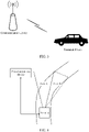
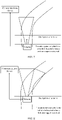
- FIG. 1 is a schematic diagram of an illumination scenario of a visual blind area in a curve
- FIG. 2 is a schematic diagram of an illumination scenario of a roadside blind area.
- a road section ahead is a curve
- an illumination range of a vehicle lamp of a vehicle is an area A
- an area B in the curve is a visual blind area because the area B is not within the illumination range of the vehicle lamp.
- knowing a road condition in the area B in advance may provide important reference for a driving decision in the curve.
- a vehicle travels on a straight road
- an illumination range of a vehicle lamp of the vehicle is an area A
- an area in which a pedestrian is located is an area B
- the area B is not within the illumination range of the vehicle lamp.
- knowing a location of the pedestrian in the area B in advance is critical for implementing safe driving.
- the foregoing two lighting scenarios are merely examples of scenarios provided for describing the solutions of this application.
- a person skilled in the art may properly transform the foregoing two scenarios to obtain another scenario, for example, a scenario obtained by replacing the pedestrian in the scenario shown in FIG. 2 with a construction site, a roadblock, a road warning sign, or the like.
- An area that has a safety risk and that is not within an illumination range of a vehicle lamp may be considered as an area B.
- the conventional technology provides two lighting systems for a curve at night: a light source supplementing curve lighting system and an adaptive front-lighting system (adaptive front-lighting system, AFS for short).
- a supplementary light source such as a corner lamp or a static curve low beam lamp needs to be additionally disposed on the vehicle.
- the driver may turn on a corresponding supplementary light source by rotating a steering wheel, to illuminate the visual blind area in the curve.
- the AFS may adaptively rotate a corresponding angle based on a steering lock angle of the vehicle or a trajectory of a gravity center of the vehicle, to illuminate the visual blind area in the curve.
- both of the foregoing two curve lighting systems are triggered to be enabled by rotating the steering wheel after the driver autonomously determines that there is a curve in front of the vehicle.
- the vehicle has entered the curve.
- the driver may need to observe a road condition of the visual blind area in the curve before the vehicle enters the curve, to provide reference for a steering operation of the driver. It is clear that lighting operations of the foregoing two curve lighting systems are delayed, and neither of the foregoing two curve lighting systems is applicable to lighting of the roadside blind area shown in FIG. 2 . As a result, safety of driving the vehicle is low.
- inventions of this application provide a vehicle lighting control method.
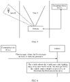
- the method may be implemented based on a system architecture shown in FIG. 3 .
- the system architecture shown in FIG. 3 includes a roadside communications device and a terminal device.
- the roadside communications device includes but is not limited to a base station (Base Transceiver Station, BTS for short) in Global System for Mobile Communications (Global System for Mobile Communication, GSM for short) or Code Division Multiple Access (Code Division Multiple Access, CDMA for short), a base station (NodeB, NB for short) in Wideband Code Division Multiple Access (Wideband Code Division Multiple Access, WCDMA for short), an evolved NodeB (evolved NodeB, eNB for short) in an LTE network, an access point (access point, AP), a relay station, a base station in a 5G network or an NR, a micro base station, a mobile micro base station, a roadside unit RSU, a mobile phone, a tablet computer, a notebook computer, a smartwatch, and another device that can implement a corresponding function.
- BTS Base Transceiver Station
- GSM Global System for Mobile Communication
- CDMA Code Division Multiple Access
- NodeB NodeB
- NB Wideband Code Division Multiple Access
- the terminal device includes but is not limited to a control component in a vehicle, a lighting system in a vehicle, a mobile terminal in a vehicle, a vehicle, and another device that can implement a corresponding function.
- the following describes the solutions of this application by using an example in which the terminal device is a vehicle. It should be noted that a solution obtained when a step performed by the vehicle is performed by foregoing another terminal device other than the vehicle also falls within the protection scope of this application.
- the roadside communications device and the vehicle may be connected by using an existing wireless communications technology.
- the roadside communications device may be installed at a specific location according to a requirement.
- the communications device may be installed beside the curve.
- the communications device may be installed on a roadside.
- a vehicle automatically adjusts a lighting mode through communication between the roadside communications device and the vehicle in FIG. 3 , to illuminate a visual blind area in advance.
- Embodiments of this application no longer depend on active triggering of the driver. Therefore, a problem of the delayed lighting operation in the conventional technology can be avoided.
- Embodiments of this application are more than applicable to an illumination scenario of a visual blind area in a curve and are applicable to an illumination scenario similar to the roadside blind area shown in FIG. 2 . This greatly improves driving safety.
- the following describes in detail a process of communication between a vehicle and a roadside communications device in two scenarios in FIG. 4 and FIG. 5 .
- FIG. 6 is a schematic flowchart of Embodiment 1 of a vehicle lighting control method according to an embodiment of this application. As shown in FIG. 6 , the vehicle lighting control method provided in this embodiment specifically includes the following steps.
- a roadside communications device sends a first message to a vehicle.
- the first message includes at least one parameter, and the at least one parameter includes but is not limited to a start point of a curve, a type of a first location at a first time point, a geographical location of the first location, a moving speed at the first location, or a first timing advance.
- S602 The vehicle adjusts the vehicle into a first lighting mode in advance based on the first message before the vehicle passes a blind area in the curve, to illuminate the blind area in the curve.
- the vehicle may determine a first turn-on moment based on the at least one parameter, and the first turn-on moment is advanced by the first timing advance relative to a moment at which the vehicle travels past the blind area in the curve.
- the vehicle passes a blind area in the curve means that the vehicle arrives at a location closest to the blind area in the curve on a travel path, or arrives at the blind area.
- the parameter in the first message is the start point of the curve.
- a location point of the vehicle when the vehicle receives the first message may be first obtained.
- a target distance between the vehicle and the start point of the curve when the first message is received is determined based on the location point of the vehicle and the start point of the curve.
- a target time period is determined based on a vehicle velocity of the vehicle when the first message is received and the target distance.
- the first turn-on moment may be obtained by adding the target time period to a moment at which the vehicle receives the first message.
- the vehicle may determine a first turn-on location based on the at least one parameter; and adjust the vehicle into the first lighting mode when the vehicle arrives at the first turn-on location, to illuminate the blind area in the curve.
- a start point of a curve may be used as the first turn-on location.
- the vehicle may determine a first distance based on the at least one parameter; and adjust the vehicle into the first lighting mode when the vehicle arrives at a location that is the first distance from the blind area in the curve, to illuminate the blind area in the curve.
- the first distance may be preset. For example, a distance of 100 m relative to the blind area in the curve is defined as the first distance.
- the foregoing describes a process of determining an occasion for adjusting a lighting mode of the vehicle in the illumination scenario of the visual blind area in the curve.
- the following describes an implementation of adjusting the lighting mode of the vehicle.
- the vehicle may adjust the vehicle into the first lighting mode based on at least one of a type of a turned-on lamp, a quantity of turned-on lamps, projection light intensity, a projection angle, or a turn-on moment.
- the vehicle may be adjusted into the first lighting mode by enabling a corresponding sub-module of the corner light, the static curve low beam lamp, and/or the matrix headlamp.
- the first message sent by the communications device to the vehicle may further include direction information.
- the direction information may indicate a direction of the curve relative to the vehicle.
- the direction information may indicate that the curve is on a left side or a right side of the vehicle.
- the vehicle After the vehicle receives the first message, when the adjustment occasion described above is met, the vehicle adjusts, based on the direction information, the vehicle into the first lighting mode by turning on a supplementary light source close to the inner side of the curve. This reduces power consumption of the vehicle.
- the first message sent by the communications device to the vehicle may further include a curvature radius and direction information.
- the curvature radius is a curvature radius at a location on the curve that is a preset distance from the start point of the curve.
- the direction information may also be used to indicate a direction of the curve relative to the vehicle.
- the vehicle may calculate, based on the curvature radius, an angle that a lamp part in the follow-up lighting system needs to rotate, and when the adjustment occasion described above is met, control the lamp part in the follow-up lighting system to rotate the angle toward a side indicated by the direction information, so as to adjust the vehicle into the first lighting mode to implement lighting of the visual blind area in the curve.
- FIG. 8 is a schematic diagram of an effect achieved by using an embodiment of this application in an illumination scenario of a visual blind area in a curve.
- the vehicle lighting mode can be automatically adjusted without manual intervention of a driver, and the visual blind area in the curve can be illuminated before the vehicle enters the curve. This helps the driver observe a road condition in the visual blind area, and greatly improves safety of driving on the curve.
- the roadside communications device sends the first message to the vehicle.
- the first message includes at least one parameter.
- the vehicle may adjust the vehicle into the first lighting mode in advance based on the at least one parameter before the vehicle passes the blind area in the curve, to illuminate the blind area in the curve. Because an adjustment action in the foregoing method is automatically performed by the vehicle without intervention of the driver, there is no problem of delayed lighting caused due to dependency on active triggering of the driver in the conventional technology.
- illumination is controlled to be enabled at the start point of the curve, so that the driver can observe a road condition in the visual blind area in the curve in advance. This ensures safety of driving the vehicle on the curve.
- FIG. 9 is a schematic flowchart of Embodiment 2 of a vehicle lighting control method according to an embodiment of this application. As shown in FIG. 9 , the vehicle lighting control method provided in this embodiment of this application specifically includes the following steps.
- a roadside communications device sends a first message to a vehicle.
- the first message may include at least one of a first turn-on moment, a first timing advance, a first turn-on location, or a first distance.
- the first turn-on moment is used to indicate the vehicle to adjust the vehicle into a first lighting mode at the first turn-on moment, to illuminate a roadside blind area.
- the first timing advance is used to indicate the vehicle to adjust the vehicle into the first lighting mode at a moment advanced by the first timing advance relative to a moment at which the vehicle travels past the roadside blind area, to illuminate the roadside blind area.
- the first turn-on location is used to indicate the vehicle to adjust the vehicle into the first lighting mode when the vehicle arrives at the first turn-on location, to illuminate the roadside blind area.
- the first distance is used to indicate the vehicle to adjust the vehicle into the first lighting mode when the vehicle arrives at a location that is the first distance from the roadside blind area, to illuminate the roadside blind area.
- the following describes a manner of obtaining the first turn-on moment, the first timing advance, the first turn-on location, or the first distance.
- a first location of the vehicle at a first time point and first motion status data relative to the roadside communications device may be first obtained, and then the first turn-on moment, the first timing advance, the first turn-on location, or the first distance is determined based on the first location and the first motion status data.
- the roadside communications device may obtain the first location of the vehicle at the first time point and the first motion status data of the vehicle relative to the roadside communications device by using detection technologies such as photographing, radar, laser, and an induction loop.
- the first motion status data includes but is not limited to a velocity, an acceleration, an angular velocity, or angular acceleration.
- the following uses an example in which the first motion status data is a velocity to describe in detail a process of determining the first turn-on moment, the first timing advance, the first turn-on location, and the first distance.
- the roadside communications device may first calculate a distance between the location point A and the location point B, and then duration used by the vehicle to travel from the location point A to the location point B is calculated based on the distance and the velocity v that are obtained through calculation.
- the first turn-on moment may be obtained by adding the duration to a moment at which the vehicle arrives at the location point A.
- the start point of the roadside blind area may be used as the first turn-on location.
- the roadside communications device may first calculate a distance between the location point A and the location point B, and then duration used by the vehicle to travel from the location point A to the location point B is calculated based on the distance and the velocity v that are obtained through calculation.
- the duration may be used as the first timing advance.
- the first distance may be preset. For example, a distance of 100 m relative to the roadside blind area is defined as the first distance.
- At least one of the first turn-on moment, the first timing advance, the first turn-on location, or the first distance may be determined based on the roadside blind area.
- information about a planned navigation path of the vehicle may be first obtained, and then at least one of the first turn-on moment, the first timing advance, the first turn-on location, or the first distance may be determined based on the navigation path information.
- a manner in which the roadside communications device sends the first message to the vehicle includes but is not limited to an underlying unicast manner, an underlying multicast manner, and/or an encryption manner.
- S902 The vehicle adjusts the vehicle into the first lighting mode in advance based on the first message before the vehicle passes the roadside blind area, to illuminate the roadside blind area.
- the vehicle may adjust the vehicle into the first lighting mode at the first turn-on moment, to illuminate the roadside blind area.
- the vehicle may adjust the vehicle into the first lighting mode at the moment advanced by the first timing advance relative to the moment at which the vehicle travels past the roadside blind area, to illuminate the roadside blind area.
- the vehicle determines, based on location information of the vehicle, whether the vehicle arrives at the first turn-on location, and adjusts the vehicle into the first lighting mode when the vehicle arrives at the first turn-on location, to illuminate the roadside blind area.
- the vehicle may monitor a distance between the vehicle and the roadside communications device in real time in a manner such as radar, and when the distance between the vehicle and the roadside communications device is the first distance, adjusts the vehicle into the first lighting mode to illuminate the roadside blind area.
- the method provided in this embodiment further includes: determining, based on the first message, that a minimum distance between the roadside blind area and the planned navigation path of the vehicle does not exceed a first threshold, to avoid a problem of high energy consumption caused by illuminating the roadside blind area when the vehicle is so far away from the roadside blind area that the roadside blind area cannot constitute a safety risk to vehicle driving.
- the foregoing describes a process of determining an occasion for adjusting a lighting mode of the vehicle in the illumination scenario of the roadside blind area.
- the following describes a process of adjusting the lighting mode of the vehicle.
- a corresponding sub-module of a high beam lamp and/or a matrix headlamp may be directly turned on to adjust the vehicle into the first lighting mode, to illuminate the roadside blind area.
- FIG. 11 is a schematic diagram of an effect achieved by using an embodiment of this application in an illumination scenario of a roadside blind area.
- the vehicle lighting mode can be automatically adjusted without manual intervention of a driver, so that the driver can clearly observe road conditions and pedestrian conditions on two sides of a road. This improves driving safety.
- the roadside communications device sends the first message to the vehicle.
- the first message includes at least one of the first turn-on moment, the first timing advance, the first turn-on location, or the first distance.
- the vehicle After receiving the first message, and before passing the roadside blind area, the vehicle adjusts the vehicle into the first lighting mode in advance to illuminate the roadside blind area.
- An action of adjusting the lighting mode in the foregoing method is automatically performed by the vehicle without intervention of the driver, so that the driver can clearly observe road conditions and pedestrian conditions on two sides of the road in advance. This improves driving safety.
- FIG. 12 shows an example in which there are two roadside blind areas: an area B and an area C on two roadsides.
- FIG. 13 is a schematic flowchart of Embodiment 3 of a vehicle lighting control method according to an embodiment of this application.
- the vehicle lighting control method provided in this embodiment includes the following steps.
- a roadside communications device sends a first message to a vehicle.
- the first message is further used to prompt the vehicle to illuminate a second roadside blind area, and the second roadside blind area is also near a travel path that the vehicle is to pass through.
- the roadside blind area in the foregoing embodiment is referred to as a first roadside blind area.
- the first message further includes at least one of a second turn-on moment, a second timing advance, a second turn-on location, or a second distance.
- the second turn-on moment is used to indicate the vehicle to adjust the vehicle into a second lighting mode at the second turn-on moment, to simultaneously illuminate the first roadside blind area and the second roadside blind area.
- the second timing advance is used to indicate the vehicle to adjust the vehicle into the second lighting mode at a moment advanced by the second timing advance relative to a moment at which the vehicle travels past the second roadside blind area, to simultaneously illuminate the first roadside blind area and the second roadside blind area.
- the second turn-on location is used to indicate the vehicle to adjust the vehicle into the second lighting mode when the vehicle arrives at the second turn-on location, to simultaneously illuminate the first roadside blind area and the second roadside blind area.
- the second distance is used to indicate the vehicle to adjust the vehicle into the second lighting mode when the vehicle arrives at a location that is the second distance from the second roadside blind area, to simultaneously illuminate the first roadside blind area and the second roadside blind area.
- S1302 The vehicle adjusts the vehicle into the second lighting mode in advance based on the first message before the vehicle passes the second roadside blind area, to simultaneously illuminate the first roadside blind area and the second roadside blind area.
- the vehicle may adjust the vehicle into the second lighting mode at the second turn-on moment, to illuminate the first roadside blind area and the second roadside blind area.
- the vehicle may adjust the vehicle into the second lighting mode at the moment advanced by the second timing advance relative to the moment at which the vehicle travels past the roadside blind area, to illuminate the first roadside blind area and the second roadside blind area.
- the vehicle determines, based on location information of the vehicle, whether the vehicle arrives at the second turn-on location, and adjusts the vehicle into the second lighting mode when the vehicle arrives at the second turn-on location, to illuminate the first roadside blind area and the second roadside blind area.
- the vehicle may monitor a distance between the vehicle and the roadside communications device in real time in a manner such as radar, and when the distance between the vehicle and the roadside communications device is the second distance, adjusts the vehicle into the second lighting mode to illuminate the first roadside blind area and the second roadside blind area.
- the foregoing describes a process of determining an occasion for adjusting a lighting mode of the vehicle in the illumination scenario of the roadside blind area.
- the following describes a process of adjusting the lighting mode of the vehicle.
- a corresponding sub-module of a high beam lamp and/or a matrix headlamp may be directly turned on to adjust the vehicle into the second lighting mode, to illuminate the first roadside blind area and the second roadside blind area.
- S1301 and S 1302 may be replaced with the following manner:
- the second roadside communications device sends a second message to the vehicle.
- the second message is used to prompt the vehicle to illuminate the second roadside blind area, and the second roadside blind area is near the travel path that the vehicle is to pass through.
- the vehicle adjusts the vehicle into the second lighting mode based on the second message before the vehicle passes the second roadside blind area, to simultaneously illuminate the first roadside blind area and the second roadside blind area.
- a process in which the vehicle adjusts the vehicle into the second lighting mode in advance based on the second message is similar to a process in which the vehicle adjusts the vehicle into the first lighting mode in advance based on the first message in the foregoing embodiment. Details are not described herein again in this application.
- FIG. 14 is a schematic diagram of an effect achieved by using an embodiment of this application in an illumination scenario of a roadside blind area.
- the plurality of roadside blind areas can be simultaneously illuminated, so that a driver can clearly observe all areas having safety risks on a road. This further improves driving safety.
- the first message carries at least one of the second turn-on moment, the second timing advance, the second turn-on location, or the second distance, so that the vehicle can adjust the vehicle into the second lighting mode in advance before passing the second roadside blind area, to simultaneously illuminate the first roadside blind area and the second roadside blind area.
- the plurality of roadside blind areas are simultaneously illuminated, and the driver can clearly observe all areas having safety risks on the road. This further improves driving safety.
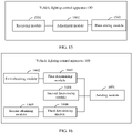
- FIG. 15 is a schematic diagram of a structure of an embodiment of a vehicle lighting control apparatus 150 according to an embodiment of this application.
- An entity corresponding to the vehicle lighting control apparatus 150 includes but is not limited to a device that can implement a corresponding function, such as a control component in the vehicle described above, a lighting system in the vehicle, a mobile terminal in the vehicle, and the vehicle.
- the vehicle lighting control apparatus 150 provided in this embodiment of this application includes a receiving module 1501 and an adjustment module 1502.
- the receiving module 1501 is configured to receive a first message sent by a first roadside communications device.
- the first message is used to prompt the vehicle to illuminate a first target, and the first target is near a travel path that the vehicle is to pass through.
- the adjustment module 1502 is configured to adjust the vehicle into a first lighting mode in advance based on the first message before the vehicle passes the first target, to illuminate the first target.
- step S602 or step S902 for a specific implementation process, refer to step S602 or step S902 in the foregoing method embodiments.
- the first message includes at least one parameter
- the adjustment module 1502 may be specifically configured to: determine a first turn-on moment based on the at least one parameter, where the first turn-on moment is advanced by a first timing advance relative to a moment at which the vehicle travels past the first target; and adjust the vehicle into the first lighting mode at the first turn-on moment.
- the first message includes at least one parameter
- the adjustment module 1502 may be specifically configured to: determine a first turn-on location based on the at least one parameter; and adjust the vehicle into the first lighting mode when the vehicle arrives at the first turn-on location, to illuminate the first target.
- the first message includes at least one parameter
- the adjustment module 1502 may be specifically configured to: determine a first distance based on the at least one parameter; and adjust the vehicle into the first lighting mode when the vehicle arrives at a location that is the first distance from the first target, to illuminate the first target.
- the first message includes a first turn-on moment
- the adjustment module 1502 is specifically configured to adjust the vehicle into the first lighting mode at the first turn-on moment.
- the first message includes a first turn-on location
- the adjustment module 1502 is specifically configured to adjust the vehicle into the first lighting mode when the vehicle arrives at the first turn-on location, to illuminate the first target.
- the first message includes a first distance
- the adjustment module 1502 is specifically configured to adjust the vehicle into the first lighting mode when the vehicle arrives at a location that is the first distance from the first target, to illuminate the first target.
- the adjustment module 1502 is configured to adjust at least one of a type of a turned-on lamp, a quantity of turned-on lamps, projection light intensity, a projection angle, or a turn-on moment.
- the vehicle lighting control apparatus 150 provided in this embodiment further includes a determining module 1503, configured to determine, based on the first message, that a minimum distance between the first target and a planned navigation path of the vehicle does not exceed a first threshold.
- the receiving module 1501 is further configured to receive a second message sent by a second roadside communications device.
- the second message is used to prompt the vehicle to illuminate a second target, and the second target is near the travel path that the vehicle is to pass through.
- the adjustment module 1502 is further configured to adjust the vehicle into a second lighting mode in advance based on the second message before the vehicle passes the second target, to simultaneously illuminate the first target and the second target.
- the first message is further used to prompt the vehicle to illuminate a second target, and the second target is near the travel path that the vehicle is to pass through.
- the adjustment module 1502 is further configured to adjust the vehicle into a second lighting mode in advance based on the first message before the vehicle passes the second target, to simultaneously illuminate the first target and the second target.
- the vehicle lighting control apparatus provided in this embodiment of this application may perform the steps on the vehicle side in any one of the foregoing method embodiments. Implementation principles and beneficial effects thereof are similar, and details are not described herein again.
- FIG. 16 is a schematic diagram of a structure of an embodiment of a vehicle lighting control apparatus 160 according to an embodiment of this application.
- An entity corresponding to the vehicle lighting control apparatus 130 include but is not limited to the foregoing base station, micro base station, mobile micro base station, mobile phone, tablet computer, notebook computer, smartwatch, and another device that can implement a corresponding function.
- the vehicle lighting control apparatus 160 provided in this embodiment of this application includes a sending module 1601.
- the sending module 1601 is configured to send a first message to a vehicle.
- the first message is used to prompt the vehicle to illuminate a first target, and the first target is near a travel path that the vehicle is to pass through.
- the first message includes at least one of a first turn-on moment, a first timing advance, a first turn-on location, or a first distance.
- the first turn-on moment is used to indicate the vehicle to adjust the vehicle into a first lighting mode at the first turn-on moment, to illuminate the first target.
- the first timing advance is used to indicate the vehicle to adjust the vehicle into the first lighting mode at a moment advanced by the first timing advance relative to a moment at which the vehicle travels past the first target, to illuminate the first target.
- the first turn-on location is used to indicate to the vehicle to adjust the vehicle into the first lighting mode when the vehicle arrives at the first turn-on location, to illuminate the first target.
- the first distance is used to indicate to the vehicle to adjust the vehicle into the first lighting mode when the vehicle arrives at a location that is the first distance from the first target, to illuminate the first target.
- the vehicle lighting control apparatus 160 further includes: a first obtaining module 1602, configured to obtain a first location of the vehicle at a first time point and first motion status data relative to a roadside communications device; and a first determining module 1603, configured to determine at least one of the first turn-on moment, the first timing advance, the first turn-on location, or the first distance based on the first location and the first motion status data.
- a first obtaining module 1602 configured to obtain a first location of the vehicle at a first time point and first motion status data relative to a roadside communications device
- a first determining module 1603 configured to determine at least one of the first turn-on moment, the first timing advance, the first turn-on location, or the first distance based on the first location and the first motion status data.
- the vehicle lighting control apparatus 160 provided in this embodiment further includes a second determining module 1604, configured to determine at least one of the first turn-on moment, the first timing advance, the first turn-on location, or the first distance based on the first target.
- a second determining module 1604 configured to determine at least one of the first turn-on moment, the first timing advance, the first turn-on location, or the first distance based on the first target.
- the vehicle lighting control apparatus 160 provided in this embodiment further includes: a second obtaining module 1605, configured to obtain information about a planned navigation path of the vehicle; a third determining module 1606, configured to determine at least one of the first turn-on moment, the first timing advance, the first turn-on location, or the first distance based on the navigation path information.
- the first message is further used to prompt the vehicle to illuminate a second target, and the second target is near the travel path that the vehicle is to pass through.
- the first message further includes at least one of a second turn-on moment, a second timing advance, a second turn-on location, or a second distance.
- the second turn-on moment is used to indicate the vehicle to adjust the vehicle into a second lighting mode at the second turn-on moment, to simultaneously illuminate the first target and the second target.
- the second timing advance is used to indicate the vehicle to adjust the vehicle into the second lighting mode at a moment advanced by the second timing advance relative to a moment at which the vehicle travels past the second target, to simultaneously illuminate the first target and the second target.
- the second turn-on location is used to indicate to the vehicle to adjust the vehicle into the second lighting mode when the vehicle arrives at the second turn-on location, to simultaneously illuminate the first target and the second target.
- the second distance is used to indicate to the vehicle to adjust the vehicle into the second lighting mode when the vehicle arrives at a location that is the second distance from the second target, to simultaneously illuminate the first target and the second target.
- the vehicle lighting control apparatus provided in this embodiment of this application may perform the steps on the roadside communications device side in any one of the foregoing method embodiments. Implementation principles and beneficial effects thereof are similar, and details are not described herein again.
- FIG. 17 is a schematic diagram of a hardware structure 170 according to an embodiment of this application.
- the hardware structure may be a hardware structure in a vehicle, or may be a hardware structure in a roadside communications device.
- the hardware structure 170 includes a memory 1701 and a processor 1702.
- the memory 1701 is configured to store program instructions
- the processor 1702 is configured to invoke the program instructions in the memory 1701 to perform the steps on the vehicle side or the steps on the roadside communications device side in the foregoing method embodiments. Implementation principles and technical effects thereof are similar, and details are not described herein again.
- the terminal device further includes a communications interface 1703, and the communications interface 1703 may be connected to the processor 1702 by using a bus 1704.
- the processor 1702 may control the communications interface 1703 to implement receiving and sending functions of the hardware structure 170.
- This application further provides a readable storage medium.
- the readable storage medium stores executable instructions.
- at least one processor of a terminal device implements the steps on the vehicle side or the steps on the roadside communications device side in the foregoing method embodiments. Implementation principles and technical effects thereof are similar, and details are not described herein again.
- the program product includes computer programs (namely, executable instructions).
- the computer programs are stored in a readable storage medium.
- the processor may read the computer programs from the readable storage medium, and the processor executes the computer programs to perform the steps on the vehicle side or the steps on the roadside communications device side in the foregoing method embodiments. Implementation principles and beneficial effects thereof are similar, and details are not described herein again.
- the disclosed device and method may be implemented in other manners.
- the described apparatus embodiment is merely an example.
- division into modules is merely logical function division.
- a plurality of modules may be combined or integrated into another system, or some features may be ignored or not performed.
- the displayed or discussed mutual couplings or direct couplings or communication connections may be implemented through some interfaces.
- the indirect couplings or communication connections between the apparatuses or modules may be implemented in electronic, mechanical, or other forms.
- modules described as separate parts may or may not be physically separate, and parts displayed as modules may or may not be physical units, and may be located in one position, or may be distributed on a plurality of network units. Some or all of the modules may be selected according to actual requirements to achieve the objectives of the solutions in embodiments of this application.
- function modules in embodiments of this application may be integrated into one processing unit, or each of the modules may exist alone physically, or two or more modules are integrated into one unit.
- the unit integrated by the modules may be implemented in a form of hardware, or may be implemented in a form of hardware plus a software function unit.
- the integrated unit may be stored in a computer-readable storage medium.
- the software function module is stored in a storage medium and includes several instructions to enable a computer device (which may be a personal computer, a server, or a network device) or a processor (English: processor) to perform some steps of the methods in embodiments of this application.
- the processor may be a central processing unit (central processing unit, CPU), or may be another general-purpose processor, a digital signal processor (digital signal processor, DSP), an application-specific integrated circuit (application-specific integrated circuit, ASIC), or the like.
- the general-purpose processor may be a microprocessor, or the processor may be any conventional processor or the like. The steps of the method disclosed with reference to this application may be directly performed by a hardware processor, or may be performed by a combination of hardware and a software module in a processor.
- the memory may include a high-speed RAM memory, or may include a non-volatile memory NVM such as at least one magnetic disk memory, or may include a USB flash drive, a removable hard disk, a read-only memory, a magnetic disk, an optical disc, or the like.
- NVM non-volatile memory
- the memory may include a high-speed RAM memory, or may include a non-volatile memory NVM such as at least one magnetic disk memory, or may include a USB flash drive, a removable hard disk, a read-only memory, a magnetic disk, an optical disc, or the like.
- the bus may be an industry standard architecture (industry standard architecture, ISA) bus, a peripheral component interconnect (peripheral component, PCI) bus, an extended industry standard architecture (extended industry standard architecture, EISA) bus, or the like.
- the bus may be classified into an address bus, a data bus, a control bus, and the like.
- the bus in the accompanying drawings of this application is not limited to only one bus or only one type of bus.
- All or some of the foregoing embodiments may be implemented by using software, hardware, firmware, or any combination thereof.
- software is used to implement embodiments, all or some of the embodiments may be implemented in a form of a computer program product.
- the computer program product includes one or more computer instructions. When the computer program instructions are loaded and executed on a computer, all or some of the procedures or functions according to embodiments of this application are generated.
- the computer may be a general-purpose computer, a dedicated computer, a computer network, or another programmable apparatus.
- the computer instructions may be stored in a computer-readable storage medium or may be transmitted from a computer-readable storage medium to another computer-readable storage medium.
- the computer instructions may be transmitted from a website, computer, server, or data center to another website, computer, server, or data center in a wired (for example, a coaxial cable, an optical fiber, or a digital subscriber line (DSL)) or wireless (for example, infrared, radio, or microwave) manner.
- the computer-readable storage medium may be any usable medium accessible by the computer, or a data storage device, such as a server or a data center, integrating one or more usable media.
- the usable medium may be a magnetic medium (for example, a floppy disk, a hard disk, or a magnetic tape), an optical medium (for example, a DVD), a semiconductor medium (for example, a solid state disk (solid state disk, SSD)), or the like.
- a magnetic medium for example, a floppy disk, a hard disk, or a magnetic tape
- an optical medium for example, a DVD
- a semiconductor medium for example, a solid state disk (solid state disk, SSD)
Landscapes
- Engineering & Computer Science (AREA)
- Mechanical Engineering (AREA)
- Computer Networks & Wireless Communication (AREA)
- Signal Processing (AREA)
- Lighting Device Outwards From Vehicle And Optical Signal (AREA)
Applications Claiming Priority (1)
| Application Number | Priority Date | Filing Date | Title |
|---|---|---|---|
| PCT/CN2020/081013 WO2021189275A1 (zh) | 2020-03-25 | 2020-03-25 | 车辆照明控制方法和设备 |
Publications (2)
| Publication Number | Publication Date |
|---|---|
| EP4112380A1 true EP4112380A1 (de) | 2023-01-04 |
| EP4112380A4 EP4112380A4 (de) | 2023-04-19 |
Family
ID=75208069
Family Applications (1)
| Application Number | Title | Priority Date | Filing Date |
|---|---|---|---|
| EP20927524.7A Withdrawn EP4112380A4 (de) | 2020-03-25 | 2020-03-25 | Verfahren und vorrichtung zur steuerung der beleuchtung eines fahrzeugs |
Country Status (6)
| Country | Link |
|---|---|
| US (1) | US20230015287A1 (de) |
| EP (1) | EP4112380A4 (de) |
| JP (1) | JP2023518522A (de) |
| KR (1) | KR20220156598A (de) |
| CN (1) | CN112601677A (de) |
| WO (1) | WO2021189275A1 (de) |
Families Citing this family (3)
| Publication number | Priority date | Publication date | Assignee | Title |
|---|---|---|---|---|
| CN113778108B (zh) * | 2021-10-09 | 2023-07-21 | 招商局检测车辆技术研究院有限公司 | 一种基于路侧感知单元的数据采集系统及数据处理方法 |
| US12579885B2 (en) | 2023-08-22 | 2026-03-17 | Qualcomm Incorporated | Automatic light distribution system |
| CN120229174A (zh) * | 2023-12-29 | 2025-07-01 | 长城汽车股份有限公司 | 控制灯光的方法、装置、车辆及存储介质 |
Family Cites Families (22)
| Publication number | Priority date | Publication date | Assignee | Title |
|---|---|---|---|---|
| JPH10166934A (ja) * | 1996-12-13 | 1998-06-23 | Koito Mfg Co Ltd | 車輌用灯具装置 |
| JP2008062856A (ja) * | 2006-09-08 | 2008-03-21 | Denso Corp | ヘッドライト制御システム |
| DE102008061747A1 (de) * | 2007-12-13 | 2009-06-25 | Continental Teves Ag & Co. Ohg | Verfahren und System zum Anpassen eines Fahrzeugs |
| DE102011081367A1 (de) * | 2011-08-23 | 2013-02-28 | Robert Bosch Gmbh | Verfahren zur Steuerung einer Lichtaussendung eines Scheinwerfers eines Fahrzeugs |
| US9669755B2 (en) * | 2011-11-08 | 2017-06-06 | GM Global Technology Operations LLC | Active vision system with subliminally steered and modulated lighting |
| DE102014011117A1 (de) * | 2014-07-26 | 2016-01-28 | Audi Ag | Fahrerassistenzsystem, Kraftfahrzeug und Betriebsverfahren |
| DE102015010932B4 (de) * | 2015-08-18 | 2018-07-12 | Audi Ag | Verfahren zum Betreiben einer Beleuchtungsvorrichtung, Beleuchtungsvorrichtung, Kraftfahrzeug und ortsfeste Erfassungsvorrichtung |
| CN108349429B (zh) * | 2015-10-27 | 2021-03-23 | 株式会社小糸制作所 | 车辆用照明装置、车辆系统及车辆 |
| DE102015225410A1 (de) * | 2015-12-16 | 2017-06-22 | Bayerische Motoren Werke Aktiengesellschaft | Verfahren und Steuereinheit zur Vermeidung von Gefahrensituation im Straßenverkehr |
| US9731645B1 (en) * | 2016-04-07 | 2017-08-15 | Valeo North America, Inc. | Cooperative adaptive lighting system using vehicle to target or object communication |
| FR3053513A1 (fr) * | 2016-07-01 | 2018-01-05 | Peugeot Citroen Automobiles Sa | Dispositif et procede d'asssistance pour l'eclairage d'un obstacle situe devant un vehicule |
| JP2018052365A (ja) * | 2016-09-29 | 2018-04-05 | 株式会社オートネットワーク技術研究所 | 制御システム、車載制御装置及びコンピュータプログラム |
| CN108237967B (zh) * | 2016-12-23 | 2021-06-08 | 电信科学技术研究院 | 一种进行灯光控制的方法和设备 |
| CN106740431A (zh) * | 2017-01-09 | 2017-05-31 | 长沙理工大学 | 一种基于车路协同的汽车大灯自动控制系统 |
| DE102017209240B4 (de) * | 2017-05-31 | 2024-09-19 | Volkswagen Aktiengesellschaft | Verfahren zur Ansteuerung wenigstens einer Vorrichtung von einem Kraftfahrzeug |
| US11245469B2 (en) * | 2017-07-27 | 2022-02-08 | The Regents Of The University Of Michigan | Line-of-sight optical communication for vehicle-to-vehicle (v2v) and vehicle-to-infrastructure (v2i) mobile communication networks |
| CN107804215A (zh) * | 2017-10-27 | 2018-03-16 | 合肥工业大学 | 一种具有危险提示功能的智能车灯控制系统 |
| US20190160998A1 (en) * | 2017-11-29 | 2019-05-30 | GM Global Technology Operations LLC | Headlight control based on messaging and sensor data |
| JP6557843B1 (ja) * | 2018-12-05 | 2019-08-14 | パナソニックIpマネジメント株式会社 | 車両の制御装置、制御システム、及び制御プログラム |
| CN110027465B (zh) * | 2019-04-18 | 2021-05-28 | 奇瑞汽车股份有限公司 | 车灯控制方法、装置、存储介质及车载终端 |
| CN110246333B (zh) * | 2019-06-18 | 2020-12-15 | 华人运通(上海)自动驾驶科技有限公司 | 车灯控制方法、装置、设备和计算机可读存储介质 |
| CN110335488A (zh) * | 2019-07-24 | 2019-10-15 | 深圳成谷科技有限公司 | 一种基于车路协同的车辆自动驾驶方法和装置 |
-
2020
- 2020-03-25 KR KR1020227036506A patent/KR20220156598A/ko not_active Ceased
- 2020-03-25 EP EP20927524.7A patent/EP4112380A4/de not_active Withdrawn
- 2020-03-25 CN CN202080004742.5A patent/CN112601677A/zh active Pending
- 2020-03-25 JP JP2022558043A patent/JP2023518522A/ja active Pending
- 2020-03-25 WO PCT/CN2020/081013 patent/WO2021189275A1/zh not_active Ceased
-
2022
- 2022-09-23 US US17/951,823 patent/US20230015287A1/en not_active Abandoned
Also Published As
| Publication number | Publication date |
|---|---|
| US20230015287A1 (en) | 2023-01-19 |
| EP4112380A4 (de) | 2023-04-19 |
| KR20220156598A (ko) | 2022-11-25 |
| JP2023518522A (ja) | 2023-05-01 |
| WO2021189275A1 (zh) | 2021-09-30 |
| CN112601677A (zh) | 2021-04-02 |
Similar Documents
| Publication | Publication Date | Title |
|---|---|---|
| US20230015287A1 (en) | Vehicle Lighting Control Method and Device | |
| JP6918059B2 (ja) | 画像投射装置および画像投射方法 | |
| US9789809B2 (en) | Method and device for aligning an illuminated area of a headlight of a vehicle as a function of the surroundings of the vehicle | |
| CN107264385B (zh) | 使用车辆与目标或物体通信的合作自适应照明系统 | |
| US10124716B1 (en) | Automated high beam headlight operation | |
| US20210046862A1 (en) | Method and apparatus for controlling a lighting system of a vehicle | |
| US10562439B2 (en) | Techniques for optimizing vehicle headlights based on situational awareness | |
| US10513216B2 (en) | Method for controlling the light distribution of vehicle headlights and vehicle | |
| US12403817B2 (en) | Control apparatus, control method, and program for controlling vehicle headlamps | |
| US20190160998A1 (en) | Headlight control based on messaging and sensor data | |
| US20190389366A1 (en) | Motor Vehicle Comprising a Lighting Module for Generating a Set of Symbols | |
| WO2016095154A1 (en) | Vehicle headlight control | |
| CN105835753A (zh) | 用于调节车辆的驾驶员辅助设备的至少一个参数的方法和控制设备 | |
| JP4556533B2 (ja) | 車両用歩行者報知装置及び歩行者報知方法 | |
| KR101987750B1 (ko) | 후방 차량에 추월 정보를 제공하는 장치 및 방법 | |
| US20240359624A1 (en) | Mitigation of accidents due to glare from sun or headlights | |
| KR102276410B1 (ko) | 차량의 충돌 회피 시스템 및 방법 | |
| JP2012180051A (ja) | 車両用前照灯制御装置および車両用前照灯システム | |
| KR102455836B1 (ko) | 보행자 감지를 위한 차량 제어 장치 및 방법 | |
| JP2012185669A (ja) | 車両検知装置及びこれを用いる車両配光制御装置 | |
| KR101934752B1 (ko) | 적응형 전조등 빔패턴 제어 장치 및 방법 | |
| US12150024B2 (en) | Method for reporting dazzling caused by a headlight system of an oncoming vehicle and for determining an incorrect position of the headlight system | |
| KR102217597B1 (ko) | 적응형 전조등 시스템의 제어장치 및 방법 | |
| US20160023607A1 (en) | Forward viewing camera configured to control outside electro-optic mirror | |
| KR20250150290A (ko) | 자율 주행 제어 장치와 방법 및 컴퓨터 프로그램 |
Legal Events
| Date | Code | Title | Description |
|---|---|---|---|
| STAA | Information on the status of an ep patent application or granted ep patent |
Free format text: STATUS: THE INTERNATIONAL PUBLICATION HAS BEEN MADE |
|
| PUAI | Public reference made under article 153(3) epc to a published international application that has entered the european phase |
Free format text: ORIGINAL CODE: 0009012 |
|
| STAA | Information on the status of an ep patent application or granted ep patent |
Free format text: STATUS: REQUEST FOR EXAMINATION WAS MADE |
|
| 17P | Request for examination filed |
Effective date: 20220930 |
|
| AK | Designated contracting states |
Kind code of ref document: A1 Designated state(s): AL AT BE BG CH CY CZ DE DK EE ES FI FR GB GR HR HU IE IS IT LI LT LU LV MC MK MT NL NO PL PT RO RS SE SI SK SM TR |
|
| A4 | Supplementary search report drawn up and despatched |
Effective date: 20230320 |
|
| RIC1 | Information provided on ipc code assigned before grant |
Ipc: H04W 4/44 20180101ALN20230314BHEP Ipc: B60Q 1/08 20060101ALI20230314BHEP Ipc: B60Q 1/04 20060101ALI20230314BHEP Ipc: B60Q 1/02 20060101AFI20230314BHEP |
|
| DAV | Request for validation of the european patent (deleted) | ||
| DAX | Request for extension of the european patent (deleted) | ||
| STAA | Information on the status of an ep patent application or granted ep patent |
Free format text: STATUS: THE APPLICATION IS DEEMED TO BE WITHDRAWN |
|
| 18D | Application deemed to be withdrawn |
Effective date: 20231017 |