EP4112399B1 - Séchoir à air chaud à chambre double et système pneumatique - Google Patents
Séchoir à air chaud à chambre double et système pneumatique Download PDFInfo
- Publication number
- EP4112399B1 EP4112399B1 EP21181963.6A EP21181963A EP4112399B1 EP 4112399 B1 EP4112399 B1 EP 4112399B1 EP 21181963 A EP21181963 A EP 21181963A EP 4112399 B1 EP4112399 B1 EP 4112399B1
- Authority
- EP
- European Patent Office
- Prior art keywords
- valve
- regeneration
- air dryer
- pneumatic
- chamber air
- Prior art date
- Legal status (The legal status is an assumption and is not a legal conclusion. Google has not performed a legal analysis and makes no representation as to the accuracy of the status listed.)
- Active
Links
Images
Classifications
-
- F—MECHANICAL ENGINEERING; LIGHTING; HEATING; WEAPONS; BLASTING
- F15—FLUID-PRESSURE ACTUATORS; HYDRAULICS OR PNEUMATICS IN GENERAL
- F15B—SYSTEMS ACTING BY MEANS OF FLUIDS IN GENERAL; FLUID-PRESSURE ACTUATORS, e.g. SERVOMOTORS; DETAILS OF FLUID-PRESSURE SYSTEMS, NOT OTHERWISE PROVIDED FOR
- F15B21/00—Common features of fluid actuator systems; Fluid-pressure actuator systems or details thereof, not covered by any other group of this subclass
- F15B21/04—Special measures taken in connection with the properties of the fluid
- F15B21/048—Arrangements for compressed air preparation, e.g. comprising air driers, air condensers, filters, lubricators or pressure regulators
-
- B—PERFORMING OPERATIONS; TRANSPORTING
- B60—VEHICLES IN GENERAL
- B60T—VEHICLE BRAKE CONTROL SYSTEMS OR PARTS THEREOF; BRAKE CONTROL SYSTEMS OR PARTS THEREOF, IN GENERAL; ARRANGEMENT OF BRAKING ELEMENTS ON VEHICLES IN GENERAL; PORTABLE DEVICES FOR PREVENTING UNWANTED MOVEMENT OF VEHICLES; VEHICLE MODIFICATIONS TO FACILITATE COOLING OF BRAKES
- B60T17/00—Component parts, details, or accessories of power brake systems not covered by groups B60T8/00, B60T13/00 or B60T15/00, or presenting other characteristic features
- B60T17/002—Air treatment devices
- B60T17/004—Draining and drying devices
-
- B—PERFORMING OPERATIONS; TRANSPORTING
- B01—PHYSICAL OR CHEMICAL PROCESSES OR APPARATUS IN GENERAL
- B01D—SEPARATION
- B01D53/00—Separation of gases or vapours; Recovering vapours of volatile solvents from gases; Chemical or biological purification of waste gases, e.g. engine exhaust gases, smoke, fumes, flue gases, aerosols
- B01D53/02—Separation of gases or vapours; Recovering vapours of volatile solvents from gases; Chemical or biological purification of waste gases, e.g. engine exhaust gases, smoke, fumes, flue gases, aerosols by adsorption, e.g. preparative gas chromatography
- B01D53/04—Separation of gases or vapours; Recovering vapours of volatile solvents from gases; Chemical or biological purification of waste gases, e.g. engine exhaust gases, smoke, fumes, flue gases, aerosols by adsorption, e.g. preparative gas chromatography with stationary adsorbents
- B01D53/047—Pressure swing adsorption
-
- B—PERFORMING OPERATIONS; TRANSPORTING
- B01—PHYSICAL OR CHEMICAL PROCESSES OR APPARATUS IN GENERAL
- B01D—SEPARATION
- B01D53/00—Separation of gases or vapours; Recovering vapours of volatile solvents from gases; Chemical or biological purification of waste gases, e.g. engine exhaust gases, smoke, fumes, flue gases, aerosols
- B01D53/26—Drying gases or vapours
- B01D53/261—Drying gases or vapours by adsorption
-
- F—MECHANICAL ENGINEERING; LIGHTING; HEATING; WEAPONS; BLASTING
- F15—FLUID-PRESSURE ACTUATORS; HYDRAULICS OR PNEUMATICS IN GENERAL
- F15B—SYSTEMS ACTING BY MEANS OF FLUIDS IN GENERAL; FLUID-PRESSURE ACTUATORS, e.g. SERVOMOTORS; DETAILS OF FLUID-PRESSURE SYSTEMS, NOT OTHERWISE PROVIDED FOR
- F15B21/00—Common features of fluid actuator systems; Fluid-pressure actuator systems or details thereof, not covered by any other group of this subclass
- F15B21/008—Reduction of noise or vibration
-
- F—MECHANICAL ENGINEERING; LIGHTING; HEATING; WEAPONS; BLASTING
- F15—FLUID-PRESSURE ACTUATORS; HYDRAULICS OR PNEUMATICS IN GENERAL
- F15B—SYSTEMS ACTING BY MEANS OF FLUIDS IN GENERAL; FLUID-PRESSURE ACTUATORS, e.g. SERVOMOTORS; DETAILS OF FLUID-PRESSURE SYSTEMS, NOT OTHERWISE PROVIDED FOR
- F15B21/00—Common features of fluid actuator systems; Fluid-pressure actuator systems or details thereof, not covered by any other group of this subclass
- F15B21/04—Special measures taken in connection with the properties of the fluid
- F15B21/044—Removal or measurement of undissolved gas, e.g. de-aeration, venting or bleeding
-
- B—PERFORMING OPERATIONS; TRANSPORTING
- B01—PHYSICAL OR CHEMICAL PROCESSES OR APPARATUS IN GENERAL
- B01D—SEPARATION
- B01D2259/00—Type of treatment
- B01D2259/45—Gas separation or purification devices adapted for specific applications
- B01D2259/4566—Gas separation or purification devices adapted for specific applications for use in transportation means
-
- F—MECHANICAL ENGINEERING; LIGHTING; HEATING; WEAPONS; BLASTING
- F15—FLUID-PRESSURE ACTUATORS; HYDRAULICS OR PNEUMATICS IN GENERAL
- F15B—SYSTEMS ACTING BY MEANS OF FLUIDS IN GENERAL; FLUID-PRESSURE ACTUATORS, e.g. SERVOMOTORS; DETAILS OF FLUID-PRESSURE SYSTEMS, NOT OTHERWISE PROVIDED FOR
- F15B2211/00—Circuits for servomotor systems
- F15B2211/30—Directional control
- F15B2211/32—Directional control characterised by the type of actuation
- F15B2211/327—Directional control characterised by the type of actuation electrically or electronically
-
- F—MECHANICAL ENGINEERING; LIGHTING; HEATING; WEAPONS; BLASTING
- F15—FLUID-PRESSURE ACTUATORS; HYDRAULICS OR PNEUMATICS IN GENERAL
- F15B—SYSTEMS ACTING BY MEANS OF FLUIDS IN GENERAL; FLUID-PRESSURE ACTUATORS, e.g. SERVOMOTORS; DETAILS OF FLUID-PRESSURE SYSTEMS, NOT OTHERWISE PROVIDED FOR
- F15B2211/00—Circuits for servomotor systems
- F15B2211/60—Circuit components or control therefor
- F15B2211/63—Electronic controllers
- F15B2211/6303—Electronic controllers using input signals
- F15B2211/6306—Electronic controllers using input signals representing a pressure
-
- F—MECHANICAL ENGINEERING; LIGHTING; HEATING; WEAPONS; BLASTING
- F15—FLUID-PRESSURE ACTUATORS; HYDRAULICS OR PNEUMATICS IN GENERAL
- F15B—SYSTEMS ACTING BY MEANS OF FLUIDS IN GENERAL; FLUID-PRESSURE ACTUATORS, e.g. SERVOMOTORS; DETAILS OF FLUID-PRESSURE SYSTEMS, NOT OTHERWISE PROVIDED FOR
- F15B2211/00—Circuits for servomotor systems
- F15B2211/80—Other types of control related to particular problems or conditions
- F15B2211/885—Control specific to the type of fluid, e.g. specific to magnetorheological fluid
- F15B2211/8855—Compressible fluids, e.g. specific to pneumatics
Definitions
- the invention relates to a twin chamber air dryer for a pneumatic system of a commercial vehicle and a pneumatic system comprising a twin chamber air dryer.
- Pneumatic systems of commercial vehicles in general comprise a compressor driven by an engine shaft of the vehicle engine and an air dryer device for drying or dehumidifying the compressed air supplied by the compressor.
- the air dryer therefore receives the compressed air from the compressor, dehumidifies it by means of replaceable desiccant cartridges and delivers the dried, compressed air in on-load phases (supply phases) to consumer circuits, in particular by means of a multi circuit protection valve connected to the air dryer.
- the desiccant cartridges are regenerated only in pumping phases, in which dried, compressed air from the line behind one of the desiccant cartridges is guided in reverse direction through the second desiccant cartridge to an exhaust of the air dryer.
- these regeneration phases are time-controlled.
- a mechanical governor valve is provided for controlling the system pressure provided by the air dryer and stopping further supply when reaching a cut-out pressure, in order to prevent the pneumatic system from overpressure by the purge valve activating.
- the mechanical governor is realized by a valve devices and outputs a pneumatic signal to a compressor head of the compressor, which compressor head comprises a valve for switching the compressor into an off-load mode thereby stopping the air supply to the air dryer.
- Cut-out pressures provided by a mechanical governor are generally fixed by the internal specific valve equipment of the governor, which is a drawback of such a prior art assembly.
- twin chamber air dryers which comprise two desiccant cartridges to be operated in an alternating manner.
- one desiccant cartridge can be regenerated when the other desiccant cartridge is in its supply phase for dehumidifying the supplied compressed air.
- a toggling valve assembly is provided for switching or toggling the compressed air from a supply inlet port of the twin chamber air dryer to either a first air dryer line with the first desiccant cartridge or a second air dryer line with the second desiccant cartridge.
- Check valves or non-return valves are provided in order to connect the air dryer lines to a common supply outlet and a common regeneration line.
- the document WO 2017 050 408 A1 describes a twin chamber air dryer cartridge with a regeneration valve and a governor valve.
- one disadvantage of the prior art is an interaction of the air streams of the two air dryer lines.
- the regeneration air stream in one of the air dryer lines reduces the supply air flow provided by the other air dryer line during its on-load phase.
- the control of the on-load phases and regeneration phases are often realized by a timer element, which initiates and stops these phases according to preset time intervals.
- a timer element which initiates and stops these phases according to preset time intervals.
- such a time-control with fixed time intervals does not permit a higher flexibility according to the current air demand and air consumption.
- twin chamber air dryer systems tend to toggle or switch between a first and second supply phase, in which the air is transmitted through the first or second desiccant cartridge, respectively.
- An object of the invention is to provide a twin chamber air dryer for a pneumatic system of a commercial vehicle and a pneumatic system comprising such a twin chamber air dryer which enable a flexible, safe and energy-efficient operation.
- the inventive twin chamber air dryer comprises at least four pneumatic ports, which are a supply inlet port to be connected to a compressor or an external source of compressed air, a supply outlet for supplying dried compressed air to a pneumatic consumer system, a compressor control outlet for delivering a compressor pressure signal to said compressor, and an exhaust outlet.
- the twin chamber air dryer comprises a first and a second desiccant cartridge, which are preferably replaceable, a toggling valve assembly for switching between said first and second desiccant cartridge, a purge valve, and a solenoid valve assembly. Furthermore, additional means like a safety valve, non-return valves and a heater can be provided.
- the solenoid valve assembly comprises three solenoid valves, which are a direction control solenoid valve, a regeneration solenoid valve, and a governor solenoid valve. All three solenoid valves can be independently controlled by an electronic control unit, thereby enabling a separation of the individual on-load phases (supply phases) and regeneration phases of the respective desiccant cartridge. Further, the compressor can be switched by the governor solenoid valve, thus facilitating to control the compressor independently of the on-load phases and regeneration phases of the desiccant cartridges. By realizing the compressor control independently of the control of the desiccant cartridges, an energy-efficient operation is possible; further, a starting phase of the twin chamber air dryer is improved.
- This feature of an electrically controlled solenoid valve assembly with the above mentioned three solenoid valves enables the benefit of an individual operation, wherein in the air supply provided by one desiccant cartridge is not reduced by the regeneration phase of the other desiccant cartridge. Further, this assembly is energy-efficient, since the regeneration phase can be controlled independently of the on-load phase of the other desiccant cartridge.
- the purge valve is provided for connecting the supply inlet port to the exhaust outlet; it comprises a blocking basic position and is activated by the governor solenoid valve.
- the governor solenoid valve is electrically controlled by the governor control signal and outputs a pneumatic control signal fed to the pneumatic unloader control port of the compressor; further the pneumatic control signal is preferably fed to the pneumatic control port of the purge valve.
- This combined control process i.e. stopping the compressor and switching the purge valve, provides the inventive advantage, that a supply of additional compressed air can be stopped immediately. Stopping the compressor only does not necessarily block the supply of compressed air, since the compressor, depending on the type, can still supply some air flow in its idle mode even after receiving the pneumatic unloader control signal at least for a specific running down period.
- the direction control solenoid valve controls the toggling valve assembly and switches the toggling valves between their respective positions.
- the regeneration solenoid valve is provided for initiating a regenerating phase; thus, the direction control solenoid valve defines, which of the desiccant cartridges can be operated in the regeneration phase initiated by the regeneration solenoid valve.
- the on-load phase and the regeneration phase of each desiccant cartridge can be individually controlled, independently of the other desiccant cartridge.
- a regeneration phase of one desiccant cartridge can be started even in a compressor off-load mode, in which the other air dryer line is not providing compressed air to the common supply outlet.
- the pressure for the regeneration phases can be taken from the pneumatic system or consumer circuits behind the twin chamber air dryer.
- the solenoid valve assembly provides not only on-load phases and regeneration phases, but also passive phases of each desiccant cartridge, in which no through-flow of air through the desiccant cartridge, neither in its supply direction nor its regeneration direction, is provided. This reduces the energy consumption of the twin chamber air dryer by avoiding unnecessary operation.
- an additional safety valve is provided, which releases the pressure supplied by the compressor to the supply inlet port and therefore protects the pneumatic system against overpressure coming from the compressor, in particular sudden and unexpected overpressure.
- the safety valve and the purge valve both are preferably connected between the supply inlet and an exhaust; however, the safety valve is in particular-not switched by a control signal but it opens above a specific safety valve pressure value.
- the toggling valve assembly comprises a first and a second toggling valve, for switching a first air dryer line with the first desiccant cartridge and a second air dryer line with the second desiccant cartridge into an on-load phase (supply phase) or a regeneration phase.
- the toggling valve assembly preferably comprises a first toggling valve, which is pneumatically controlled by the direction control solenoid valve, and a pneumatically controlled second toggling valve, wherein the toggling valves are preferably 3/2 valves.
- the first toggling valve is preferably provided between the supply inlet and the first air dryer line with the first desiccant cartridge; in its blocking position it is preferably exhausting the first air dryer line in order to enable a regeneration phase of the first desiccant cartridge; in its open position it enables an on-load phase of the first desiccant cartridge.
- the second toggling valve is switchable in order to enable an on-load phase and a regeneration phase of the second desiccant cartridge.
- At least one of said solenoid valves is an electrically controlled 3/2 valve, being connected with its electrical control port to said supply outlet and biased into its blocking basic position.
- all three solenoid valves are 3/2 valves, which facilitates a cheap and standardized manufacturing and assembling.
- the pneumatic valve equipment is provided in a first casing and the solenoid valve assembly is provided in a second casing.
- the solenoid valves can be assembled in a separate casing, thereby facilitating the use of common parts and an exchange and flexible use for different first casings and second casings. Further the safety is enhanced by separating the solenoid valves from the pneumatic valve system.
- the second casing can be fixed to the first casing, realizing a stable assembly, wherein pneumatic connections between the first casing and the second casing are realized by openings in said casings and sealings between said casings.
- additional pneumatic plumbing between the casings can be avoided, which reduces the costs and enhances the safety.
- the compressor is preferably switchable between an on-load mode and an off-load mode, wherein the off-load mode can be e.g. a switched-off mode, in which the compressor is switched off, or an idle mode of the compressor.
- the off-load mode can be e.g. a switched-off mode, in which the compressor is switched off, or an idle mode of the compressor.
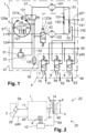
- a commercial vehicle 20 includes a pneumatic system 22, which comprises a compressor 2 connected to an engine shaft 25 of a combustion engine of the commercial vehicle 20, a twin chamber air dryer 1, an ECU (Electronic Control Unit) 10 for controlling the twin chamber air dryer 1, and a pneumatic consumer system 3 connected to the twin chamber air dryer 1; said pneumatic consumer system 3 comprises a multi circuit protection valve assembly 5, consumers circuits 4 and an alternative system pressure storage 14.
- a pneumatic system 22 which comprises a compressor 2 connected to an engine shaft 25 of a combustion engine of the commercial vehicle 20, a twin chamber air dryer 1, an ECU (Electronic Control Unit) 10 for controlling the twin chamber air dryer 1, and a pneumatic consumer system 3 connected to the twin chamber air dryer 1; said pneumatic consumer system 3 comprises a multi circuit protection valve assembly 5, consumers circuits 4 and an alternative system pressure storage 14.
- the twin chamber air dryer 1 comprises:
- the compressor 2 In its on-load mode the compressor 2 is supplying pressurized air; in its off-load mode the compressor 2 can in particular be switched OFF or be provided an idle mode.
- the ECU 10 outputs electrical control signals S1, S2, S3 to the solenoid valve assembly 6. Further the ECU 10 receives an electrical pressure control signal S4 from a pressure sensor 45 for sensing a system pressure p21.
- the pressure sensor 45 is provided at the supply outlet 21 or in the pneumatic consumer system 3 connected to the supply outlet 21, for example in one of the consumer circuits 4 connected to the multi circuit protection valve assembly 5.
- the solenoid valve assembly 6 includes a direction control solenoid valve 7 for receiving an electrical direction control signal S1, a regeneration solenoid valve 8 for receiving an electrical regeneration control signal S2, and a governor solenoid valve 9 for receiving an electrical governor control signal S3.
- the twin chamber air dryer 1 comprises a first dryer line 41 with a first desiccant cartridge 101 and a second dryer line 42 with a second desiccant cartridge 102, wherein the desiccant cartridges 101, 102 are operated alternately.
- a toggling valve assembly 121, 122 is provided for switching between the dryer lines 41, 42.
- the first and second toggling valve 121, 122 are pneumatically controlled 3/2 valves, for switching the supply inlet port 11 to either the first desiccant cartridge 101 or the second desiccant cartridge 102.
- the first toggling valve 121 remains in its open position for connecting the supply inlet port 11 to the first desiccant cartridge 101, which provides dried pressurized air into a first outlet line 51.
- the pneumatic control port 122a of the second toggling valve 122 is connected to the first outlet line 51, thereby keeping the second toggling valve 122 in its blocking position when the first outlet line 51 is pressurized. Contrary, when the first outlet line 51 is not pressurized, the second toggling valve 122 switches into its open basic position, thereby connecting the supply inlet port 11 to the second desiccant cartridge 102 and pressurizing a second outlet line 52.
- the first and second outlet line 51, 52 are connected via non-return valves 131, 132 to the supply outlet 21.
- Pressure control of the first toggling valve 121 is realized by the direction control solenoid 7 of the solenoid valve assembly 6 via a pneumatic control port 121a.
- the direction control solenoid valve 7 In its non-activated basic position the direction control solenoid valve 7 separates the supply outlet 21 from a pneumatic control port 121a of the first toggling valve 121; therefore the first toggling valve 121 remains in its open basic position, thereby keeping the second toggling valve 122 in its blocking position, as described above.
- the direction control solenoid valve 7 is switched into its activated open position, thereby connecting the supply outlet 21 to the pneumatic control port 121a and switching the first toggling valve 121 into its activated blocking position, in which the first air dryer line 41 is connected to the exhaust line 53, which is connected to the exhaust outlet 30 via a silencer 125.
- the second toggling valve 122 connects the second air dryer line 42 to the exhaust line 53 and the exhaust outlet 30.
- the electrical direction control signal S1 enables a toggling or switching between the operation via the first desiccant cartridge 101 and via the second desiccant cartridge 102, which are therefore operated in an alternating manner.
- the respective non-active (passive) desiccant cartridge 101, 102 can be operated either in a passive phase (off phase) or in a regeneration phase.
- the regeneration solenoid valve 8 is blocking the connection from the supply outlet 21 to a check valve assembly 141, 142, which connects a regeneration line 48 to the output of the desiccant cartridges 101, 102.
- the regeneration solenoid valve 8 switches into its open position and connects the supply outlet 21 to the regeneration line 48, and therefore, the regeneration check valve 141 or 142 of the non-pressurized outlet line 51 or 52 opens and fills the respective outlet line 51 or 52 with the pressurized air provided at the supply outlet 21, thus starting a first regeneration phase of the first desiccant cartridge 101 or a second regeneration phase of the second desiccant cartridge 102 depending on the position of the first and second toggling valve 121, 122.
- This pressurized air provided at the supply outlet 21 can therefore be delivered by the other outlet line, i.e. by the second outlet line 52 for regeneration of the first desiccant cartridge 101 and, accordingly, by the first outlet line 51 for regeneration of the second desiccant cartridge 102.
- the pressurized air can also be taken from the multi circuit protection valve assembly 5 and the consumers circuits 4 connected to the supply outlet 21, which offers a regeneration phase of the desiccant cartridge 101 or 102 depending on the position of the first and second toggling valve 121, 122.
- the regeneration solenoid valve 8 in its ON position, the regeneration of the passive desiccant cartridge 102 or 101 is started, thereby regenerating the passive desiccant cartridge and discharging the wet or humidified air via the toggling valve 122 or 121, which is open in its regeneration direction.
- the purge valve 126 itself or a purge valve area around the purge valve 126 can be electrically heated by an electrical heater device 127, in order to avoid freezing of the purge valve 126 or the purge valve area.
Landscapes
- Engineering & Computer Science (AREA)
- Chemical & Material Sciences (AREA)
- Analytical Chemistry (AREA)
- Mechanical Engineering (AREA)
- General Engineering & Computer Science (AREA)
- Fluid Mechanics (AREA)
- Physics & Mathematics (AREA)
- General Chemical & Material Sciences (AREA)
- Oil, Petroleum & Natural Gas (AREA)
- Chemical Kinetics & Catalysis (AREA)
- Transportation (AREA)
- Drying Of Gases (AREA)
- Valves And Accessory Devices For Braking Systems (AREA)
Claims (14)
- Sécheur d'air à double chambre (1) pour un système pneumatique (22) d'un véhicule utilitaire (20), ledit sécheur d'air à double chambre (1) comprenant :un orifice d'entrée d'alimentation (11) destiné à être connecté à un compresseur (2), une sortie d'alimentation (21) pour fournir de l'air comprimé séché à un système de consommation pneumatique (3), une sortie de commande de compresseur (40) pour délivrer un signal de déchargeur pneumatique (p40), une sortie d'échappement (30),une première cartouche de dessiccation (101) et une seconde cartouche de dessiccation (102), pour être actionnées alternativement,un ensemble soupape de basculement (121, 122) pour commuter entre ladite première cartouche de dessiccation (101) et ladite seconde cartouche de dessiccation (102), une vanne de purge à commande pneumatique (126) commutable entre une position de base de blocage et une position activée pour raccorder ledit orifice d'entrée d'alimentation (11) à ladite sortie d'échappement (30), et un ensemble électrovanne (6),ledit ensemble électrovanne (6) comprenant- une électrovanne de commande directionnelle (7) recevant un signal de commande de direction électrique (S1) et commandant ledit ensemble soupape de basculement (121, 122),- une électrovanne de régénération (8) recevant un signal de commande de régénération électrique (S2) et fournissant de l'air sous pression dans des phases de régénération desdites cartouches de dessiccation (101, 102), et- une électrovanne de régulateur (9) recevant un signal de commande de régulateur électrique (S3), commandant ladite vanne de purge (126), et délivrant en sortie ledit signal de déchargeur pneumatique (p40), dans lequel lesdites électrovannes (7, 8, 9) peuvent être mises en fonctionnement indépendamment par lesdits signaux de commande électrique (S1, S21, S3).
- Sécheur d'air à double chambre (1) selon la revendication 1,
dans lequel chaque cartouche de dessiccation (101, 102) peut fonctionner dans une phase sur charge, une phase de régénération et une phase passive, respectivement. - Sécheur d'air à double chambre (1) selon l'une des revendications précédentes, comprenant en outre une soupape de sécurité (32) pour libérer une pression d'entrée (p11) au niveau dudit orifice d'entrée d'alimentation (11).
- Sécheur d'air à double chambre (1) selon l'une des revendications précédentes, dans lequel ledit ensemble soupape de basculement (121, 121) comprend une première soupape de basculement à commande pneumatique (121) raccordée à ladite première cartouche de dessiccation (101)et une seconde vanne de basculement à commande pneumatique (122) raccordée à ladite seconde cartouche de dessiccation (102),dans lequel ladite première vanne de basculement (121) est commandée pneumatiquement par ladite électrovanne de commande directionnelle (7) et ladite seconde vanne de basculement (122) est commandée par un signal pneumatique provenant de ladite première cartouche de dessiccation (101).
- Sécheur d'air à double chambre (1) selon la revendication 4, dans lequel ladite première vanne de basculement (121) et ladite seconde vanne de basculement (122) sont des vannes 3/2, qui sont polarisées dans leur position de base ouverte pour une phase en charge et activées dans leur position fermée pour une phase de régénération, respectivement.
- Sécheur d'air à double chambre (1) selon l'une des revendications précédentes, dans lequel un système double clapet anti-retour est prévu, comprenant deux clapets anti-retour (131), (132) qui sont reliés à ladite sortie d'alimentation commune (21).
- Sécheur d'air à double chambre (1) selon l'une des revendications précédentes, dans lequel ledit signal de déchargeur pneumatique (p40) délivré par ladite électrovanne de régulateur (9) est- délivré en sortie au niveau de ladite sortie de commande de compresseur (40), pour commander un mode compresseur, et- alimenté en outre à un orifice de commande pneumatique (126a) de ladite vanne de purge (126), dans lequel ladite vanne de purge (126) est fournie pour raccorder en court-circuit ledit orifice d'entrée d'alimentation (11) à ladite sortie d'échappement (30) en fonction dudit signal de déchargeur pneumatique (p40).
- Sécheur d'air à double chambre (1) selon l'une des revendications précédentes, dans lequel un dispositif de chauffage (127) est prévu pour chauffer électriquement au moins ladite vanne de purge (126) et/ou une zone autour de ladite vanne de purge (126), afin d'éviter sa congélation.
- Sécheur d'air à double chambre (1) selon l'une des revendications précédentes, dans lequel un silencieux (125) est installé sur une conduite d'échappement (53) pour réduire le bruit pendant la décharge d'air comprimé par le biais de ladite vanne de purge (126).
- Sécheur d'air à double chambre (1) selon l'une des revendications précédentes, dans lequel ladite électrovanne de régénération (8) est prévue pour commander une phase de régénération de ladite première cartouche de dessiccation (101) et une phase de régénération de ladite seconde cartouche de dessiccation (102),dans lequel ladite électrovanne de régénération (8) met sous pression une conduite de régénération (48) en fonction dudit signal de commande de régénération électrique (S2),ladite conduite de régénération (48) étant reliée auxdites première et seconde cartouches de dessiccation (101, 102) par le biais d'un premier clapet anti-retour de régénération (141) et d'un second clapet anti-retour de régénération (142), respectivement.
- Sécheur d'air à double chambre (1) selon l'une des revendications précédentes, dans lequel au moins l'une desdites électrovannes (7, 8, 9) est une vanne 3/2 commandée électriquement, connectée à son orifice de commande électrique (7a, 8a, 9a) à ladite unité de commande électronique (10),
dans lequel ladite vanne 3/2 commandée électriquement est polarisée dans sa position de base de blocage, pour être commutée dans sa position ouverte par son signal électrique de commande respectif (S1, S2, S3). - Sécheur d'air à double chambre (1) selon l'une des revendications précédentes, comprenantun premier boîtier (47), en particulier un boîtier moulé par matrice, logeant lesdites vannes à commande pneumatique etun boîtier de solénoïde à triple bloc (46), logeant ladite électrovanne (7, 8, 9), dans lequel ledit boîtier de solénoïde à triple bloc (46) est relié audit premier boîtier (47), etdans lequel des liaisons pneumatiques entre ledit premier boîtier (47) et ledit second boîtier (46) sont réalisées par des ouvertures dans lesdits boîtiers (46, 47) et des scellements entre lesdits boîtiers (46, 47).
- Système pneumatique (22) pour un véhicule utilitaire (20), ledit système pneumatique (22) comprenant :un sécheur d'air à double chambre (1) selon l'une des revendications précédentes, une unité de commande électronique (10) pour délivrer en sortie lesdits signaux de commande électriques (S1, S2, S3) audit ensemble électrovanne (6),un compresseur à commande pneumatique (2) alimentant ledit orifice d'entrée d'alimentation (11) en air comprimé et étant commandé pneumatiquement par ledit signal de déchargeur (p40) provenant de ladite sortie de commande de compresseur (40), etun système de consommation pneumatique (3) pour recevoir de l'air sous pression séché provenant de ladite sortie d'alimentation (21) et fournir de l'air sec comprimé pour ladite phase de régénération, dans lequel un capteur de pression (45) est fourni au niveau de ladite sortie d'alimentation (21) ou dans ledit système de consommation pneumatique (3), ledit capteur de pression (45) délivrant en sortie un signal de capteur (S4) à ladite unité de commande électronique (10).
- Véhicule utilitaire (20) comprenant un système pneumatique selon la revendication 13.
Priority Applications (3)
| Application Number | Priority Date | Filing Date | Title |
|---|---|---|---|
| EP21181963.6A EP4112399B1 (fr) | 2021-06-28 | 2021-06-28 | Séchoir à air chaud à chambre double et système pneumatique |
| CN202210634380.9A CN115899027A (zh) | 2021-06-28 | 2022-06-07 | 双腔室空气干燥器和气动系统 |
| US17/851,299 US12473936B2 (en) | 2021-06-28 | 2022-06-28 | Twin chamber air dryer and pneumatic system |
Applications Claiming Priority (1)
| Application Number | Priority Date | Filing Date | Title |
|---|---|---|---|
| EP21181963.6A EP4112399B1 (fr) | 2021-06-28 | 2021-06-28 | Séchoir à air chaud à chambre double et système pneumatique |
Publications (2)
| Publication Number | Publication Date |
|---|---|
| EP4112399A1 EP4112399A1 (fr) | 2023-01-04 |
| EP4112399B1 true EP4112399B1 (fr) | 2024-01-03 |
Family
ID=77021025
Family Applications (1)
| Application Number | Title | Priority Date | Filing Date |
|---|---|---|---|
| EP21181963.6A Active EP4112399B1 (fr) | 2021-06-28 | 2021-06-28 | Séchoir à air chaud à chambre double et système pneumatique |
Country Status (3)
| Country | Link |
|---|---|
| US (1) | US12473936B2 (fr) |
| EP (1) | EP4112399B1 (fr) |
| CN (1) | CN115899027A (fr) |
Cited By (1)
| Publication number | Priority date | Publication date | Assignee | Title |
|---|---|---|---|---|
| US20220412382A1 (en) * | 2021-06-28 | 2022-12-29 | Zf Cv Systems Europe Bv | Twin chamber air dryer and pneumatic system |
Families Citing this family (6)
| Publication number | Priority date | Publication date | Assignee | Title |
|---|---|---|---|---|
| DE102018112521A1 (de) * | 2018-05-24 | 2019-11-28 | Knorr-Bremse Systeme für Nutzfahrzeuge GmbH | Luftaufbereitungseinrichtung mit elektronischer Steuereinheit zur Versorgung mindestens eines Verbraucherkreises eines Fahrzeuges |
| EP4265494B1 (fr) * | 2022-04-21 | 2025-07-02 | ZF CV Systems Global GmbH | Unité de traitement d'air, système de gestion d'air, système pneumatique et véhicule |
| EP4530141A1 (fr) * | 2023-09-26 | 2025-04-02 | ZF CV Systems Europe BV | Dessiccateur d'air à deux chambres et système électropneumatique pour un véhicule utilitaire |
| EP4545369B1 (fr) * | 2023-10-26 | 2026-01-28 | ZF CV Systems Europe BV | Ensemble valves de protection à circuits multiples et unité de traitement d'air |
| EP4585479A1 (fr) | 2024-01-11 | 2025-07-16 | ZF CV Systems Europe BV | Système de séchage d'air et procédé de commande d'un système de véhicule pneumatique |
| EP4656887A1 (fr) * | 2024-05-28 | 2025-12-03 | Volvo Truck Corporation | Système pneumatique pour véhicule |
Family Cites Families (20)
| Publication number | Priority date | Publication date | Assignee | Title |
|---|---|---|---|---|
| US4936026A (en) * | 1989-01-26 | 1990-06-26 | Allied-Signal Inc. | Charge/purge control system for air dryer |
| US5522150A (en) * | 1994-02-14 | 1996-06-04 | Allied Signal Truck Brake Systems | Modular air dryer for compressed air with dessicant |
| US5581903A (en) * | 1994-11-22 | 1996-12-10 | Botich; Leon A. | Apparatus for heating purge gas and transmitting microwave energy for desiccant regeneration |
| US5899435A (en) * | 1996-09-13 | 1999-05-04 | Westinghouse Air Brake Co. | Molded rubber valve seal for use in predetermined type valves, such as, a check valve in a regenerative desiccant air dryer |
| GB9715155D0 (en) * | 1997-07-19 | 1997-09-24 | Domnick Hunter Ltd | A gas dryer |
| US5930910A (en) * | 1997-11-26 | 1999-08-03 | Westinghouse Air Brake Company | Purge tube with flapper valve for desiccant containing air drier |
| US6074462A (en) * | 1997-12-18 | 2000-06-13 | Alliedsignal Truck Brake Systems Co. | Air dryer reservoir module components |
| GB0113205D0 (en) * | 2001-05-31 | 2001-07-25 | Wabco Automotive Uk Ltd | Regeneration of air dryer |
| GB0307422D0 (en) * | 2003-03-31 | 2003-05-07 | Walker Filtration Ltd | Electronic control device for gas dryer |
| US6785980B1 (en) * | 2003-08-05 | 2004-09-07 | Haldex Brake Corporation | Compressed air supply system |
| US7100305B2 (en) * | 2003-09-27 | 2006-09-05 | Bendix Commerical Vehicle Systems Llc | Air dryer mounting assembly |
| DE102010018949A1 (de) * | 2010-04-30 | 2011-11-03 | Wabco Gmbh | Druckluftaufbereitungseinrichtung, Druckluftversorgungssystem mit einer Druckluftaufbereitungseinrichtung und Aufbereitungsmodul hierfür sowie Verfahren zum Betrieb einer Druckluftaufbereitungseinrichtung, Steuermodul und Fahrzeug mit einer Druckluftaufbereitungseinrichtung |
| DE102012007470B4 (de) * | 2012-04-13 | 2013-11-14 | Knorr-Bremse Systeme für Nutzfahrzeuge GmbH | Druckluftaufbereitungseinrichtung für ein Fahrzeug und Verfahren zum Betreiben einer Druckluftaufbereitungseinrichtung |
| DE102013207570A1 (de) * | 2013-04-25 | 2014-10-30 | Siemens Aktiengesellschaft | Vorrichtung und Verfahren zum Trocknen von Luft sowie Schienenfahrzeug mit einer derartigen Vorrichtung |
| DE102013011785A1 (de) * | 2013-07-15 | 2015-01-15 | Wabco Gmbh | Luftbeschaffungsvorrichtung für ein Druckluftsystem eines Fahrzeugs und derartiges Druckluftsystem |
| EP3048019B1 (fr) * | 2015-01-21 | 2021-08-25 | ZF CV Systems Europe BV | Système d'adduction d'air comprimé pour un système pneumatique |
| DE102015012494A1 (de) * | 2015-09-24 | 2017-03-30 | Wabco Europe Bvba | Trocknungseinrichtung einer Druckluftversorgungsanlage |
| DE102015118744A1 (de) | 2015-11-02 | 2017-05-04 | Knorr-Bremse Systeme für Schienenfahrzeuge GmbH | Druckluftaufbereitungseinrichtung und Verfahren zum Betreiben einer solchen |
| EP3556622B1 (fr) * | 2018-04-17 | 2022-04-06 | ZF CV Systems Europe BV | Unité d'alimentation en air pour un système pneumatique d'un véhicule utilitaire |
| EP4112399B1 (fr) * | 2021-06-28 | 2024-01-03 | ZF CV Systems Europe BV | Séchoir à air chaud à chambre double et système pneumatique |
-
2021
- 2021-06-28 EP EP21181963.6A patent/EP4112399B1/fr active Active
-
2022
- 2022-06-07 CN CN202210634380.9A patent/CN115899027A/zh active Pending
- 2022-06-28 US US17/851,299 patent/US12473936B2/en active Active
Cited By (2)
| Publication number | Priority date | Publication date | Assignee | Title |
|---|---|---|---|---|
| US20220412382A1 (en) * | 2021-06-28 | 2022-12-29 | Zf Cv Systems Europe Bv | Twin chamber air dryer and pneumatic system |
| US12473936B2 (en) * | 2021-06-28 | 2025-11-18 | Zf Cv Systems Europe Bv | Twin chamber air dryer and pneumatic system |
Also Published As
| Publication number | Publication date |
|---|---|
| CN115899027A (zh) | 2023-04-04 |
| EP4112399A1 (fr) | 2023-01-04 |
| US12473936B2 (en) | 2025-11-18 |
| US20220412382A1 (en) | 2022-12-29 |
Similar Documents
| Publication | Publication Date | Title |
|---|---|---|
| EP4112399B1 (fr) | Séchoir à air chaud à chambre double et système pneumatique | |
| US8801111B2 (en) | Vehicle air braking system | |
| US5209764A (en) | Compressed air system with twin air dryers | |
| CA2677459C (fr) | Systeme de fourniture d'air comprime et procede permettant de faire fonctionner un tel systeme | |
| CN102770318B (zh) | 用于机动车的压缩空气准备装置 | |
| KR102011525B1 (ko) | 압축 공기 처리 시스템, 및 이 압축 공기 처리 시스템의 작동 방법 | |
| US8544491B2 (en) | Compressed air supply system for a commercial vehicle, and method for operating a compressed air supply system | |
| JP6403678B2 (ja) | 圧縮空気供給装置および圧縮空気供給装置の動作方法 | |
| WO2007142008A1 (fr) | Système d'alimentation en air comprimé pour véhicule et dessicateur d'air | |
| EP3556622B1 (fr) | Unité d'alimentation en air pour un système pneumatique d'un véhicule utilitaire | |
| KR101908752B1 (ko) | 상용차용 압축 공기 공급 장치 및 압축 공기 공급 장치의 작동 방법 | |
| CN107548438A (zh) | 特别是用于制备压缩空气的切换组件 | |
| US8616231B2 (en) | Valve device for a compressed air supply device and compressed air supply system | |
| JP2021506660A (ja) | 商用車のための装置 | |
| EP3113994B1 (fr) | Sécheurs d'air arrangés en parallèle pour un flux d'air élevé | |
| JP5101290B2 (ja) | 圧縮空気供給装置並びに該圧縮空気供給装置の運転のための方法 | |
| EP3995373B1 (fr) | Appareil de dessiccation d'air à commande directe par solénoïde | |
| CN119900931A (zh) | 多回路保护阀组件及空气处理单元 | |
| CN121568861A (zh) | 压缩空气供给设备、压缩空气供给系统、车辆和运行方法 | |
| JP2002523286A (ja) | エアドライヤ | |
| CN121569119A (zh) | 压缩空气供给设备、压缩空气供给系统、车辆和运行方法 | |
| US6991001B2 (en) | Compressed air control apparatus for compressed air systems of motor vehicles | |
| WO2024102508A1 (fr) | Appareil régulateur redondant pour un système de charge de frein à air de véhicule |
Legal Events
| Date | Code | Title | Description |
|---|---|---|---|
| PUAI | Public reference made under article 153(3) epc to a published international application that has entered the european phase |
Free format text: ORIGINAL CODE: 0009012 |
|
| STAA | Information on the status of an ep patent application or granted ep patent |
Free format text: STATUS: THE APPLICATION HAS BEEN PUBLISHED |
|
| AK | Designated contracting states |
Kind code of ref document: A1 Designated state(s): AL AT BE BG CH CY CZ DE DK EE ES FI FR GB GR HR HU IE IS IT LI LT LU LV MC MK MT NL NO PL PT RO RS SE SI SK SM TR |
|
| STAA | Information on the status of an ep patent application or granted ep patent |
Free format text: STATUS: REQUEST FOR EXAMINATION WAS MADE |
|
| 17P | Request for examination filed |
Effective date: 20230704 |
|
| RBV | Designated contracting states (corrected) |
Designated state(s): AL AT BE BG CH CY CZ DE DK EE ES FI FR GB GR HR HU IE IS IT LI LT LU LV MC MK MT NL NO PL PT RO RS SE SI SK SM TR |
|
| GRAP | Despatch of communication of intention to grant a patent |
Free format text: ORIGINAL CODE: EPIDOSNIGR1 |
|
| STAA | Information on the status of an ep patent application or granted ep patent |
Free format text: STATUS: GRANT OF PATENT IS INTENDED |
|
| RIC1 | Information provided on ipc code assigned before grant |
Ipc: B01D 53/26 20060101ALI20230814BHEP Ipc: B01D 53/04 20060101ALI20230814BHEP Ipc: B60T 17/00 20060101AFI20230814BHEP |
|
| INTG | Intention to grant announced |
Effective date: 20230919 |
|
| GRAS | Grant fee paid |
Free format text: ORIGINAL CODE: EPIDOSNIGR3 |
|
| GRAA | (expected) grant |
Free format text: ORIGINAL CODE: 0009210 |
|
| STAA | Information on the status of an ep patent application or granted ep patent |
Free format text: STATUS: THE PATENT HAS BEEN GRANTED |
|
| AK | Designated contracting states |
Kind code of ref document: B1 Designated state(s): AL AT BE BG CH CY CZ DE DK EE ES FI FR GB GR HR HU IE IS IT LI LT LU LV MC MK MT NL NO PL PT RO RS SE SI SK SM TR |
|
| REG | Reference to a national code |
Ref country code: GB Ref legal event code: FG4D |
|
| REG | Reference to a national code |
Ref country code: CH Ref legal event code: EP |
|
| REG | Reference to a national code |
Ref country code: DE Ref legal event code: R096 Ref document number: 602021008236 Country of ref document: DE |
|
| REG | Reference to a national code |
Ref country code: IE Ref legal event code: FG4D |
|
| REG | Reference to a national code |
Ref country code: LT Ref legal event code: MG9D |
|
| PG25 | Lapsed in a contracting state [announced via postgrant information from national office to epo] |
Ref country code: ES Free format text: LAPSE BECAUSE OF FAILURE TO SUBMIT A TRANSLATION OF THE DESCRIPTION OR TO PAY THE FEE WITHIN THE PRESCRIBED TIME-LIMIT Effective date: 20240103 |
|
| PG25 | Lapsed in a contracting state [announced via postgrant information from national office to epo] |
Ref country code: ES Free format text: LAPSE BECAUSE OF FAILURE TO SUBMIT A TRANSLATION OF THE DESCRIPTION OR TO PAY THE FEE WITHIN THE PRESCRIBED TIME-LIMIT Effective date: 20240103 |
|
| REG | Reference to a national code |
Ref country code: NL Ref legal event code: MP Effective date: 20240103 |
|
| REG | Reference to a national code |
Ref country code: AT Ref legal event code: MK05 Ref document number: 1646506 Country of ref document: AT Kind code of ref document: T Effective date: 20240103 |
|
| PG25 | Lapsed in a contracting state [announced via postgrant information from national office to epo] |
Ref country code: NL Free format text: LAPSE BECAUSE OF FAILURE TO SUBMIT A TRANSLATION OF THE DESCRIPTION OR TO PAY THE FEE WITHIN THE PRESCRIBED TIME-LIMIT Effective date: 20240103 |
|
| PG25 | Lapsed in a contracting state [announced via postgrant information from national office to epo] |
Ref country code: NL Free format text: LAPSE BECAUSE OF FAILURE TO SUBMIT A TRANSLATION OF THE DESCRIPTION OR TO PAY THE FEE WITHIN THE PRESCRIBED TIME-LIMIT Effective date: 20240103 |
|
| PG25 | Lapsed in a contracting state [announced via postgrant information from national office to epo] |
Ref country code: IS Free format text: LAPSE BECAUSE OF FAILURE TO SUBMIT A TRANSLATION OF THE DESCRIPTION OR TO PAY THE FEE WITHIN THE PRESCRIBED TIME-LIMIT Effective date: 20240503 |
|
| PG25 | Lapsed in a contracting state [announced via postgrant information from national office to epo] |
Ref country code: LT Free format text: LAPSE BECAUSE OF FAILURE TO SUBMIT A TRANSLATION OF THE DESCRIPTION OR TO PAY THE FEE WITHIN THE PRESCRIBED TIME-LIMIT Effective date: 20240103 |
|
| PG25 | Lapsed in a contracting state [announced via postgrant information from national office to epo] |
Ref country code: GR Free format text: LAPSE BECAUSE OF FAILURE TO SUBMIT A TRANSLATION OF THE DESCRIPTION OR TO PAY THE FEE WITHIN THE PRESCRIBED TIME-LIMIT Effective date: 20240404 |
|
| PG25 | Lapsed in a contracting state [announced via postgrant information from national office to epo] |
Ref country code: RS Free format text: LAPSE BECAUSE OF FAILURE TO SUBMIT A TRANSLATION OF THE DESCRIPTION OR TO PAY THE FEE WITHIN THE PRESCRIBED TIME-LIMIT Effective date: 20240403 Ref country code: HR Free format text: LAPSE BECAUSE OF FAILURE TO SUBMIT A TRANSLATION OF THE DESCRIPTION OR TO PAY THE FEE WITHIN THE PRESCRIBED TIME-LIMIT Effective date: 20240103 |
|
| PG25 | Lapsed in a contracting state [announced via postgrant information from national office to epo] |
Ref country code: CZ Free format text: LAPSE BECAUSE OF FAILURE TO SUBMIT A TRANSLATION OF THE DESCRIPTION OR TO PAY THE FEE WITHIN THE PRESCRIBED TIME-LIMIT Effective date: 20240103 Ref country code: AT Free format text: LAPSE BECAUSE OF FAILURE TO SUBMIT A TRANSLATION OF THE DESCRIPTION OR TO PAY THE FEE WITHIN THE PRESCRIBED TIME-LIMIT Effective date: 20240103 |
|
| PG25 | Lapsed in a contracting state [announced via postgrant information from national office to epo] |
Ref country code: RS Free format text: LAPSE BECAUSE OF FAILURE TO SUBMIT A TRANSLATION OF THE DESCRIPTION OR TO PAY THE FEE WITHIN THE PRESCRIBED TIME-LIMIT Effective date: 20240403 Ref country code: NO Free format text: LAPSE BECAUSE OF FAILURE TO SUBMIT A TRANSLATION OF THE DESCRIPTION OR TO PAY THE FEE WITHIN THE PRESCRIBED TIME-LIMIT Effective date: 20240403 Ref country code: LT Free format text: LAPSE BECAUSE OF FAILURE TO SUBMIT A TRANSLATION OF THE DESCRIPTION OR TO PAY THE FEE WITHIN THE PRESCRIBED TIME-LIMIT Effective date: 20240103 Ref country code: IS Free format text: LAPSE BECAUSE OF FAILURE TO SUBMIT A TRANSLATION OF THE DESCRIPTION OR TO PAY THE FEE WITHIN THE PRESCRIBED TIME-LIMIT Effective date: 20240503 Ref country code: HR Free format text: LAPSE BECAUSE OF FAILURE TO SUBMIT A TRANSLATION OF THE DESCRIPTION OR TO PAY THE FEE WITHIN THE PRESCRIBED TIME-LIMIT Effective date: 20240103 Ref country code: GR Free format text: LAPSE BECAUSE OF FAILURE TO SUBMIT A TRANSLATION OF THE DESCRIPTION OR TO PAY THE FEE WITHIN THE PRESCRIBED TIME-LIMIT Effective date: 20240404 Ref country code: CZ Free format text: LAPSE BECAUSE OF FAILURE TO SUBMIT A TRANSLATION OF THE DESCRIPTION OR TO PAY THE FEE WITHIN THE PRESCRIBED TIME-LIMIT Effective date: 20240103 Ref country code: BG Free format text: LAPSE BECAUSE OF FAILURE TO SUBMIT A TRANSLATION OF THE DESCRIPTION OR TO PAY THE FEE WITHIN THE PRESCRIBED TIME-LIMIT Effective date: 20240103 Ref country code: AT Free format text: LAPSE BECAUSE OF FAILURE TO SUBMIT A TRANSLATION OF THE DESCRIPTION OR TO PAY THE FEE WITHIN THE PRESCRIBED TIME-LIMIT Effective date: 20240103 |
|
| PG25 | Lapsed in a contracting state [announced via postgrant information from national office to epo] |
Ref country code: PT Free format text: LAPSE BECAUSE OF FAILURE TO SUBMIT A TRANSLATION OF THE DESCRIPTION OR TO PAY THE FEE WITHIN THE PRESCRIBED TIME-LIMIT Effective date: 20240503 Ref country code: PL Free format text: LAPSE BECAUSE OF FAILURE TO SUBMIT A TRANSLATION OF THE DESCRIPTION OR TO PAY THE FEE WITHIN THE PRESCRIBED TIME-LIMIT Effective date: 20240103 |
|
| PG25 | Lapsed in a contracting state [announced via postgrant information from national office to epo] |
Ref country code: SE Free format text: LAPSE BECAUSE OF FAILURE TO SUBMIT A TRANSLATION OF THE DESCRIPTION OR TO PAY THE FEE WITHIN THE PRESCRIBED TIME-LIMIT Effective date: 20240103 Ref country code: PT Free format text: LAPSE BECAUSE OF FAILURE TO SUBMIT A TRANSLATION OF THE DESCRIPTION OR TO PAY THE FEE WITHIN THE PRESCRIBED TIME-LIMIT Effective date: 20240503 Ref country code: PL Free format text: LAPSE BECAUSE OF FAILURE TO SUBMIT A TRANSLATION OF THE DESCRIPTION OR TO PAY THE FEE WITHIN THE PRESCRIBED TIME-LIMIT Effective date: 20240103 Ref country code: LV Free format text: LAPSE BECAUSE OF FAILURE TO SUBMIT A TRANSLATION OF THE DESCRIPTION OR TO PAY THE FEE WITHIN THE PRESCRIBED TIME-LIMIT Effective date: 20240103 |
|
| REG | Reference to a national code |
Ref country code: DE Ref legal event code: R097 Ref document number: 602021008236 Country of ref document: DE |
|
| PG25 | Lapsed in a contracting state [announced via postgrant information from national office to epo] |
Ref country code: DK Free format text: LAPSE BECAUSE OF FAILURE TO SUBMIT A TRANSLATION OF THE DESCRIPTION OR TO PAY THE FEE WITHIN THE PRESCRIBED TIME-LIMIT Effective date: 20240103 |
|
| PG25 | Lapsed in a contracting state [announced via postgrant information from national office to epo] |
Ref country code: SM Free format text: LAPSE BECAUSE OF FAILURE TO SUBMIT A TRANSLATION OF THE DESCRIPTION OR TO PAY THE FEE WITHIN THE PRESCRIBED TIME-LIMIT Effective date: 20240103 |
|
| PG25 | Lapsed in a contracting state [announced via postgrant information from national office to epo] |
Ref country code: EE Free format text: LAPSE BECAUSE OF FAILURE TO SUBMIT A TRANSLATION OF THE DESCRIPTION OR TO PAY THE FEE WITHIN THE PRESCRIBED TIME-LIMIT Effective date: 20240103 |
|
| PG25 | Lapsed in a contracting state [announced via postgrant information from national office to epo] |
Ref country code: SK Free format text: LAPSE BECAUSE OF FAILURE TO SUBMIT A TRANSLATION OF THE DESCRIPTION OR TO PAY THE FEE WITHIN THE PRESCRIBED TIME-LIMIT Effective date: 20240103 |
|
| PG25 | Lapsed in a contracting state [announced via postgrant information from national office to epo] |
Ref country code: SM Free format text: LAPSE BECAUSE OF FAILURE TO SUBMIT A TRANSLATION OF THE DESCRIPTION OR TO PAY THE FEE WITHIN THE PRESCRIBED TIME-LIMIT Effective date: 20240103 Ref country code: SK Free format text: LAPSE BECAUSE OF FAILURE TO SUBMIT A TRANSLATION OF THE DESCRIPTION OR TO PAY THE FEE WITHIN THE PRESCRIBED TIME-LIMIT Effective date: 20240103 Ref country code: RO Free format text: LAPSE BECAUSE OF FAILURE TO SUBMIT A TRANSLATION OF THE DESCRIPTION OR TO PAY THE FEE WITHIN THE PRESCRIBED TIME-LIMIT Effective date: 20240103 Ref country code: EE Free format text: LAPSE BECAUSE OF FAILURE TO SUBMIT A TRANSLATION OF THE DESCRIPTION OR TO PAY THE FEE WITHIN THE PRESCRIBED TIME-LIMIT Effective date: 20240103 Ref country code: DK Free format text: LAPSE BECAUSE OF FAILURE TO SUBMIT A TRANSLATION OF THE DESCRIPTION OR TO PAY THE FEE WITHIN THE PRESCRIBED TIME-LIMIT Effective date: 20240103 |
|
| PLBE | No opposition filed within time limit |
Free format text: ORIGINAL CODE: 0009261 |
|
| STAA | Information on the status of an ep patent application or granted ep patent |
Free format text: STATUS: NO OPPOSITION FILED WITHIN TIME LIMIT |
|
| PG25 | Lapsed in a contracting state [announced via postgrant information from national office to epo] |
Ref country code: IT Free format text: LAPSE BECAUSE OF FAILURE TO SUBMIT A TRANSLATION OF THE DESCRIPTION OR TO PAY THE FEE WITHIN THE PRESCRIBED TIME-LIMIT Effective date: 20240103 |
|
| 26N | No opposition filed |
Effective date: 20241007 |
|
| PG25 | Lapsed in a contracting state [announced via postgrant information from national office to epo] |
Ref country code: IT Free format text: LAPSE BECAUSE OF FAILURE TO SUBMIT A TRANSLATION OF THE DESCRIPTION OR TO PAY THE FEE WITHIN THE PRESCRIBED TIME-LIMIT Effective date: 20240103 |
|
| PG25 | Lapsed in a contracting state [announced via postgrant information from national office to epo] |
Ref country code: MC Free format text: LAPSE BECAUSE OF FAILURE TO SUBMIT A TRANSLATION OF THE DESCRIPTION OR TO PAY THE FEE WITHIN THE PRESCRIBED TIME-LIMIT Effective date: 20240103 |
|
| REG | Reference to a national code |
Ref country code: CH Ref legal event code: PL |
|
| PG25 | Lapsed in a contracting state [announced via postgrant information from national office to epo] |
Ref country code: LU Free format text: LAPSE BECAUSE OF NON-PAYMENT OF DUE FEES Effective date: 20240628 |
|
| PG25 | Lapsed in a contracting state [announced via postgrant information from national office to epo] |
Ref country code: IE Free format text: LAPSE BECAUSE OF NON-PAYMENT OF DUE FEES Effective date: 20240628 |
|
| PG25 | Lapsed in a contracting state [announced via postgrant information from national office to epo] |
Ref country code: BE Free format text: LAPSE BECAUSE OF NON-PAYMENT OF DUE FEES Effective date: 20240630 Ref country code: SI Free format text: LAPSE BECAUSE OF FAILURE TO SUBMIT A TRANSLATION OF THE DESCRIPTION OR TO PAY THE FEE WITHIN THE PRESCRIBED TIME-LIMIT Effective date: 20240103 Ref country code: CH Free format text: LAPSE BECAUSE OF NON-PAYMENT OF DUE FEES Effective date: 20240630 |
|
| REG | Reference to a national code |
Ref country code: BE Ref legal event code: MM Effective date: 20240630 |
|
| PGFP | Annual fee paid to national office [announced via postgrant information from national office to epo] |
Ref country code: DE Payment date: 20250402 Year of fee payment: 5 |
|
| PGFP | Annual fee paid to national office [announced via postgrant information from national office to epo] |
Ref country code: GB Payment date: 20250401 Year of fee payment: 5 |
|
| PGFP | Annual fee paid to national office [announced via postgrant information from national office to epo] |
Ref country code: FR Payment date: 20250508 Year of fee payment: 5 |
|
| PG25 | Lapsed in a contracting state [announced via postgrant information from national office to epo] |
Ref country code: FI Free format text: LAPSE BECAUSE OF FAILURE TO SUBMIT A TRANSLATION OF THE DESCRIPTION OR TO PAY THE FEE WITHIN THE PRESCRIBED TIME-LIMIT Effective date: 20240103 |
|
| PG25 | Lapsed in a contracting state [announced via postgrant information from national office to epo] |
Ref country code: CY Free format text: LAPSE BECAUSE OF FAILURE TO SUBMIT A TRANSLATION OF THE DESCRIPTION OR TO PAY THE FEE WITHIN THE PRESCRIBED TIME-LIMIT; INVALID AB INITIO Effective date: 20210628 |
|
| PG25 | Lapsed in a contracting state [announced via postgrant information from national office to epo] |
Ref country code: HU Free format text: LAPSE BECAUSE OF FAILURE TO SUBMIT A TRANSLATION OF THE DESCRIPTION OR TO PAY THE FEE WITHIN THE PRESCRIBED TIME-LIMIT; INVALID AB INITIO Effective date: 20210628 |