EP4112448B1 - Système antigivrage thermique intégré à micro-ondes - Google Patents
Système antigivrage thermique intégré à micro-ondes Download PDFInfo
- Publication number
- EP4112448B1 EP4112448B1 EP22182402.2A EP22182402A EP4112448B1 EP 4112448 B1 EP4112448 B1 EP 4112448B1 EP 22182402 A EP22182402 A EP 22182402A EP 4112448 B1 EP4112448 B1 EP 4112448B1
- Authority
- EP
- European Patent Office
- Prior art keywords
- susceptor
- waveguide
- skin
- layer
- assembly
- Prior art date
- Legal status (The legal status is an assumption and is not a legal conclusion. Google has not performed a legal analysis and makes no representation as to the accuracy of the status listed.)
- Active
Links
Images




Classifications
-
- B—PERFORMING OPERATIONS; TRANSPORTING
- B64—AIRCRAFT; AVIATION; COSMONAUTICS
- B64D—EQUIPMENT FOR FITTING IN OR TO AIRCRAFT; FLIGHT SUITS; PARACHUTES; ARRANGEMENT OR MOUNTING OF POWER PLANTS OR PROPULSION TRANSMISSIONS IN AIRCRAFT
- B64D15/00—De-icing or preventing icing on exterior surfaces of aircraft
-
- B—PERFORMING OPERATIONS; TRANSPORTING
- B32—LAYERED PRODUCTS
- B32B—LAYERED PRODUCTS, i.e. PRODUCTS BUILT-UP OF STRATA OF FLAT OR NON-FLAT, e.g. CELLULAR OR HONEYCOMB, FORM
- B32B15/00—Layered products comprising a layer of metal
- B32B15/04—Layered products comprising a layer of metal comprising metal as the main or only constituent of a layer, which is next to another layer of the same or of a different material
- B32B15/08—Layered products comprising a layer of metal comprising metal as the main or only constituent of a layer, which is next to another layer of the same or of a different material of synthetic resin
-
- B—PERFORMING OPERATIONS; TRANSPORTING
- B64—AIRCRAFT; AVIATION; COSMONAUTICS
- B64D—EQUIPMENT FOR FITTING IN OR TO AIRCRAFT; FLIGHT SUITS; PARACHUTES; ARRANGEMENT OR MOUNTING OF POWER PLANTS OR PROPULSION TRANSMISSIONS IN AIRCRAFT
- B64D33/00—Arrangement in aircraft of power plant parts or auxiliaries not otherwise provided for
- B64D33/02—Arrangement in aircraft of power plant parts or auxiliaries not otherwise provided for of combustion air intakes
-
- H—ELECTRICITY
- H05—ELECTRIC TECHNIQUES NOT OTHERWISE PROVIDED FOR
- H05B—ELECTRIC HEATING; ELECTRIC LIGHT SOURCES NOT OTHERWISE PROVIDED FOR; CIRCUIT ARRANGEMENTS FOR ELECTRIC LIGHT SOURCES, IN GENERAL
- H05B6/00—Heating by electric, magnetic or electromagnetic fields
- H05B6/64—Heating using microwaves
- H05B6/647—Aspects related to microwave heating combined with other heating techniques
- H05B6/6491—Aspects related to microwave heating combined with other heating techniques combined with the use of susceptors
-
- H—ELECTRICITY
- H05—ELECTRIC TECHNIQUES NOT OTHERWISE PROVIDED FOR
- H05B—ELECTRIC HEATING; ELECTRIC LIGHT SOURCES NOT OTHERWISE PROVIDED FOR; CIRCUIT ARRANGEMENTS FOR ELECTRIC LIGHT SOURCES, IN GENERAL
- H05B6/00—Heating by electric, magnetic or electromagnetic fields
- H05B6/64—Heating using microwaves
- H05B6/70—Feed lines
- H05B6/707—Feed lines using waveguides
-
- B—PERFORMING OPERATIONS; TRANSPORTING
- B32—LAYERED PRODUCTS
- B32B—LAYERED PRODUCTS, i.e. PRODUCTS BUILT-UP OF STRATA OF FLAT OR NON-FLAT, e.g. CELLULAR OR HONEYCOMB, FORM
- B32B2605/00—Vehicles
- B32B2605/18—Aircraft
-
- B—PERFORMING OPERATIONS; TRANSPORTING
- B64—AIRCRAFT; AVIATION; COSMONAUTICS
- B64D—EQUIPMENT FOR FITTING IN OR TO AIRCRAFT; FLIGHT SUITS; PARACHUTES; ARRANGEMENT OR MOUNTING OF POWER PLANTS OR PROPULSION TRANSMISSIONS IN AIRCRAFT
- B64D33/00—Arrangement in aircraft of power plant parts or auxiliaries not otherwise provided for
- B64D33/02—Arrangement in aircraft of power plant parts or auxiliaries not otherwise provided for of combustion air intakes
- B64D2033/0233—Arrangement in aircraft of power plant parts or auxiliaries not otherwise provided for of combustion air intakes comprising de-icing means
-
- H—ELECTRICITY
- H05—ELECTRIC TECHNIQUES NOT OTHERWISE PROVIDED FOR
- H05B—ELECTRIC HEATING; ELECTRIC LIGHT SOURCES NOT OTHERWISE PROVIDED FOR; CIRCUIT ARRANGEMENTS FOR ELECTRIC LIGHT SOURCES, IN GENERAL
- H05B2214/00—Aspects relating to resistive heating, induction heating and heating using microwaves, covered by groups H05B3/00, H05B6/00
- H05B2214/02—Heaters specially designed for de-icing or protection against icing
Definitions
- This disclosure (invention) relates generally to a thermal anti-icing system.
- a modern aircraft propulsion system may include a gas turbine engine housed within a nacelle.
- the nacelle includes an inlet structure for directing incoming air to the gas turbine engine.
- This inlet structure includes an inlet lip, an inner barrel and an outer barrel.
- the inlet lip forms a leading edge of the inlet structure.
- the inner barrel is connected to a radial inner end of the inlet lip, and at least partially forms an outer peripheral boundary of an inlet duct into the aircraft propulsion system.
- the outer barrel is connected to a radial outer end of the inlet lip, and circumscribes the inner barrel.
- the inlet lip may be susceptible to ice accumulation.
- the inlet structure may be configured with a thermal anti-icing system.
- a lip skin of the inlet lip may be configured with an electrical resistance heater.
- Such an electrical resistance heater may be attached to an interior surface of the lip skin to minimize a thermal conduction path length from the heater to an exterior surface of the lip skin / the inlet lip. While such electrical resistance heaters have various benefits, there is still room in the art for improvement.
- Damage to the lip skin and the electrical resistance heater arranged therewith following a foreign object impact may render a portion of or the entire electrical resistance heater inoperable where the damage severs one or more electrical resistance circuits within the electrical heater
- Prior art includes , EP3819220A1 and US 4365131A .
- US 4 060 212 A describes a system in which microwaves are propagated over a dielectric substrate being in contact with an ice layer.
- EP 2 915 748 A1 describes a susceptor and a coil, which creates an eddy current in the susceptor. Both the susceptor and the coil are integrated into a composite skin.
- an assembly is provided for a structure as claimed in claim 1.
- the thermal anti-icing system may also include a reflector configured to direct stray microwaves back towards the susceptor.
- the reflector may be formed by at least a portion of a third of the plurality of layers of material.
- the composite skin may extend between the exterior surface and the interior surface without interruption.
- the susceptor may be arranged between the waveguide and the exterior surface.
- the composite skin may include a first layer, a second layer and a third layer between the first layer and the second layer.
- the first layer may be configured as or otherwise include the susceptor.
- the second layer may be configured as or otherwise include the waveguide.
- the third layer may be configured from or otherwise include microwave transparent material.
- the composite skin may include a plurality of layers.
- a first of the layers may include the susceptor and the waveguide.
- the waveguide may be laterally spaced from the susceptor within the first of the layers.
- a second of the layers may be configured from or otherwise include microwave transparent material.
- At least one of the susceptor or the waveguide may be configured from or otherwise include metal.
- the susceptor may be configured from or otherwise include fiber reinforcement within a polymer matrix.
- the thermal anti-icing system may also include a reflector configured to reflect microwaves travelling away from the susceptor and the exterior surface back towards the susceptor.
- the reflector may be integrated into the composite skin between the exterior surface and the interior surface.
- the reflector may be configured from or otherwise include metal.
- the microwaves may be transmitted at a frequency between one gigahertz (1GHz) and ten gigahertz (10 GHz).
- the microwaves may be transmitted at a frequency between forty gigahertz (40 GHz) and eighty gigahertz (80 GHz).
- the microwaves may be transmitted at a frequency between twenty gigahertz (20 GHz) and twenty-five gigahertz (25 GHz).
- the microwaves may be transmitted at a frequency between one-hundred and fifty gigahertz (150 GHz) and two-hundred gigahertz (200 GHz).
- the thermal anti-icing system may also include a microwave source configured to generate the microwaves directed by the waveguide.
- the microwave sources may be configured as or otherwise include a magnetron, a klystron, a gyrotron or a solid state source.
- the assembly may also include a nacelle inlet structure for an aircraft propulsion system.
- the nacelle inlet structure may include the composite skin.
- the aircraft structure 22 includes at least one exterior skin 26; e.g., a multilayered, composite skin.
- This exterior skin 26 is configured to form an exterior surface 28 of the aircraft structure 22 such as an aerodynamic flow surface.
- the exterior skin 26, for example, may be configured with a nacelle of a propulsion system for the aircraft; e.g., the aircraft structure 22 may be a nacelle structure.
- the exterior skin 26, more particularly, may be configured as or otherwise included as part of a noselip of the nacelle.
- the exterior skin 26 may be configured with another component / structure of the aircraft such as its fuselage or a wing.
- the aircraft structure 22 and its exterior skin 26 extend laterally in a first direction (e.g., an x-axis direction) along an x-axis.
- the aircraft structure 22 and its exterior skin 26 extend laterally in a second direction (e.g., a y-axis direction) along a y-axis.
- the aircraft structure 22 and its exterior skin 26 extend vertically in a vertical direction (e.g., a z-axis direction) along a z-axis.
- the term "lateral" may be used herein to generally describe the first lateral direction, the second lateral direction and/or any other direction within the x-y plane.
- the term "vertical" may be used herein to describe a depthwise panel direction and is not limited to a gravitational up/down direction.
- the x-y plane is shown as a generally flat plane.
- the x-y plane and, thus, the aircraft structure 22 and/or its exterior skin 26 may be curved and/or follow an undulating geometry.
- the x-y plane and, thus, the aircraft structure 22 and/or its exterior skin 26 may be arcuate, cylindrical, conical, frustoconical, or tapered with or without radial undulations.
- the exterior skin 26 is configured as a relatively thin body that extends laterally within the x-y plane.
- the exterior skin 26 has a vertical thickness 30. This skin vertical thickness 30 extends vertically between opposing side surfaces 32 and 34 of the exterior skin 26, where the skin exterior surface 32 may form the structure exterior surface 28.
- the exterior skin body may be solid, non-porous vertically between the skin exterior surface 32 and the skin interior surface 34. Material(s) of the exterior skin 26 may thereby extend between the skin exterior surface 32 and the skin interior surface 34 without any interruptions; e.g., pores, voids, chambers, cavities and/or any other types of apertures.
- the present disclosure is not limited to such an exemplary solid, non-porous exterior skin configuration.
- the thermal anti-icing system 24 is configured to melt and/or prevent ice accumulation on the exterior surface 28, 32.
- the thermal anti-icing system 24 of FIG. 1 includes at least one susceptor 36 and a microwave system 38.
- the susceptor 36 is configured to absorb electromagnetic energy (e.g., microwave radiation, also referred to as "microwaves") and convert that absorbed electromagnetic energy into heat.
- the susceptor 36 may be configured as a thin layer (or strip, or wire) of material.
- the susceptor material may include, but are not limited to: indium tin oxide (ITO); aluminum (Al) or an alloy thereof; ferrous metal such as stainless steel; titanium (Ti) or an alloy thereof; Inconel alloys; chromium (Cr) or an alloy thereof; graphite; composites of metal(s) and ceramic(s) (e.g., cermets); doped silicon carbide; and/or metal oxide(s).
- the susceptor material includes (e.g., fiber) reinforcement material within a polymer matrix, where a thickness of the susceptor material may be sized to be about or exactly one-quarter (1/4) of the wavelength of the microwaves generated by the microwave system 38.
- An example of the reinforcement material is fiberglass.
- An example of the polymer matrix is thermoset epoxy resin. The present disclosure, however, is not limited to the foregoing exemplary susceptor materials.
- the microwave system 38 includes a microwave source 40 and a microwave transmission system 42.
- the microwave source 40 may be configured to generate microwaves at a frequency of, for example, between 2.3 gigahertz (GHz) and 2.6 gigahertz; e.g., at exactly or about (e.g., +/- 0.01 or 0.02) 2.45 gigahertz (GHz).
- GHz gigahertz
- the microwave source 40 may generate the microwaves at a frequency at or above 2.6 gigahertz and/or at a frequency at or below 2.3 gigahertz.
- the microwave source 40 may be configured to generate microwaves at a frequency between one and ten gigahertz; e.g., between one and three gigahertz, or more specifically between 2.2 and 2.7 gigahertz for example.
- the microwave source 40 may also or alternatively be configured to generate microwaves at a frequency between fifteen and thirty gigahertz; e.g., between twenty and twenty-five gigahertz.
- the microwave source 40 may also or alternatively be configured to generate microwaves at a frequency between forty and eighty gigahertz; e.g., between 60 and 77 gigahertz.
- the microwave source 40 may also or alternatively be configured to generate microwaves at a frequency between one-hundred and forty (140) and two-hundred and ten (210) gigahertz; e.g., between one-hundred and fifty (150) and two-hundred (200) gigahertz.
- the microwave source 40 may be configured as or otherwise include a vacuum electron device (VED) such as, but not limited to, a magnetron, a klystron and a gyrotron.
- VED vacuum electron device
- the microwave source 40 may alternatively be configured as or otherwise include a solid state device; e.g., a solid state microwave source.
- a solid state device may include one or more radio-frequency (RF) transistors configured to generate the microwaves.
- RF radio-frequency
- a solid state device may have some advantages over a vacuum electron device. For example, a solid state device may require less (e.g., 10-100x less) operational power than a vacuum electron device; e.g., 20-50 volts versus 4000 volts.
- a solid state device may have a longer useful lifetime than a vacuum electron device; e.g., 15-20 plus years versus 500-1000 hours.
- a solid state device may have a lower mass and, thus, weigh less than a vacuum electron device.
- a solid state device may have improved control over a vacuum electron device.
- the microwave source 40 may be configured to generate a continuous output (e.g., stream) of the microwaves.
- the microwave source 40 may also or alternatively be configured to generate an intermittent (e.g., pulsed) output of the microwaves.
- the microwave transmission system 42 is configured to transmit the microwaves generated by the microwave source 40 to a desired location or locations.
- the microwave transmission system 42 is further configured to selectively direct the microwaves at / to the susceptor 36 as described below in further detail.
- the microwave transmission system 42 of FIG. 1 includes one or more waveguides 44A and 44B (generally referred to as "44"); e.g., electromagnetic feed lines.
- the upstream waveguide 44A is coupled with the microwave source 40, and is configured to transmit the microwaves generated by the microwave source 40 to the downstream waveguide 44B.
- the downstream waveguide 44B is configured to direct the microwaves received from the upstream waveguide 44A at / to the susceptor 36.
- These waveguides 44 may be configured as segments of a common waveguide. Alternatively, the waveguides 44 may be configured as discrete waveguide with common or different configurations.
- One or more of the waveguides 44 may be at least partially or completely covered by an insulating material 46.
- This insulating material 46 is a microwave resistive material such as, but not limited to, metal or alumina (e.g., Al 2 O 3 ) or silica (e.g., SiO 3 ).
- metal or alumina e.g., Al 2 O 3
- silica e.g., SiO 3
- the susceptor 36 and the downstream waveguide 44B are each configured with the aircraft structure 22 and its exterior skin 26.
- the susceptor 36 is also thermally coupled with the exterior surface 28, 32.
- the susceptor 36 of FIG. 2 for example, is integrated into the exterior skin 26 vertically between the skin exterior surface 32 and the skin interior surface 34.
- the downstream waveguide 44B of FIG. 2 is also integrated into the exterior skin 26 vertically between the skin exterior surface 32 and the skin interior surface 34, where the downstream waveguide 44B is vertically between the susceptor 36 and the skin interior surface 34.
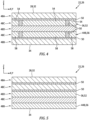
- the exterior skin 26 of FIG. 2 includes a plurality of skin layers 48A-E (generally referred to as "48"); e.g., intra-skin layers. These skin layers 48 are arranged together in a stack to form the exterior skin 26.
- the skin layers 48 are bonded to one another by an adhesive 50; e.g., a microwave transparent adhesive.
- the adhesive 50 may include, but are not limited to, thermoset epoxy resin or any other bonding material with low dielectric loss. The present disclosure, however, is not limited to the foregoing exemplary adhesive materials.
- the interior skin layer 48B may form the skin interior surface 34.
- the exterior skin layer 48A may form the exterior surface 28, 32.
- the intermediate skin layers 48C-D are arranged sequentially vertically between the other skin layers 48A and 48B.
- At least one of the skin layers 48 may at least partially or completely form the susceptor 36.
- the (e.g., exterior) intermediate skin layer 48C of FIG. 2 forms the susceptor 36.
- the intermediate skin layer 48C of FIG. 2 is (or otherwise includes) the thin layer of the susceptor material that forms the susceptor 36.
- the susceptor 36 may thereby be located within the exterior skin 26 at (e.g., on, adjacent or proximate) the exterior surface 28, 32.
- this intermediate skin layer 48C that forms the susceptor 36 may be referred to below as a susceptor layer 52.
- the susceptor 36 of FIG. 2 is configured to laterally overlap (along the x-axis and/or the y-axis) an entirety of the aircraft structure 22, the exterior skin 26 and/or the exterior surface 28, 32.
- the susceptor 36 may extend along an entire lateral extent of the exterior surface 28, 32.
- the susceptor 36 may laterally overlap (along the x-axis and/or the y-axis) a select portion of the exterior surface 28, 32.
- FIG. 1 Refer to FIG.
- the susceptor layer 52 may be configured as a strip of material with a lateral width (along the x-axis and/or the y-axis) that is less than a lateral width of the exterior skin 26 and a lateral width of the exterior surface 28, 32. With such an arrangement, thermal anti-icing of the exterior surface 28, 32 may be focused to a select region corresponding to the susceptor 36.
- the susceptor 36 may include one or more (e.g., discrete or interconnected) susceptor segments 54. Each of these susceptor segments 54 may be configured to focus thermal anti-icing to multiple corresponding regions, or provide effective coverage for the entire exterior surface 28, 32.
- the skin layers 48 may at least partially or completely form the downstream waveguide 48B.
- the (e.g., interior) intermediate skin layer 48E of FIG. 2 forms the downstream waveguide 44B.
- the intermediate skin layer 48E of FIG. 2 is (or otherwise includes) the layer of waveguide material that forms the downstream waveguide 44B.
- the downstream waveguide 44B may thereby be located within the exterior skin 26 at (e.g., on, adjacent or proximate) the skin interior surface 34.
- this intermediate skin layer 48E that forms the downstream waveguide 44B may be referred to below as a waveguide layer 56.
- the waveguide layer 56 may be configured as a strip of material with a lateral width (along the x-axis and/or the y-axis) that is less than the lateral width of the exterior skin 26 and the lateral width of the exterior surface 28, 32.
- the downstream waveguide 44B may include one or more (e.g., discrete or interconnected) waveguide segments 58. Each of these waveguide segments 58 may be configured to focus the microwaves to a respective one of the susceptor segments 54.
- each of the skin layers 48A, 48B and 48D may be configured as structural layers, support layers and/or filler layers.
- Each of the skin layers 48A and 48B may be configured as a thin sheet of reinforcement material embedded within (or otherwise arranged with) a matrix.
- the reinforcement material may include fibrous and/or granular (e.g., powder) material that is transparent to the electromagnetic energy; e.g., the microwave radiation. Examples of the reinforcement material may include, but are not limited to, fiberglass or any other material with low dielectric loss.
- the matrix material is a bonding material that is also transparent to the electromagnetic energy; e.g., the microwave radiation.
- This matrix material may be the same type as (or may be) the adhesive 50 (e.g., a microwave transparent adhesive) bonding the skin layers 48 together. In other embodiments, however, the matrix material may be different than, but complementary to for example, the adhesive material.
- the remaining (e.g., middle, intra-susceptor-waveguide) intermediate skin layer 48D may be configured as a layer of the adhesive 50 / the matrix material.
- the intermediate skin layer 48D may alternatively be configured as a thin sheet of the reinforcement material embedded within (or otherwise arranged with) the matrix. The present disclosure, however, is not limited to the foregoing exemplary reinforcement or matrix materials.
- Each of the skin layers 48 has a vertical thickness along the z-axis.
- the susceptor layer 52 vertical thickness may be equal to or different (e.g., less or greater) than the vertical thicknesses of any one or more of the remaining skin layers 48.
- the susceptor layer 52 vertical thickness is selected based on a frequency of interest of the electromagnetic radiation.
- the susceptor layer 52 vertical thickness may also or alternatively be selected to be one-quarter (1/4) of a wavelength of the electromagnetic radiation at the frequency of interest.
- the waveguide layer 56 vertical thickness may similarly be equal to or different (e.g., less or greater) than the vertical thicknesses of any one or more of the remaining skin layers 48.
- the present disclosure is not limited to such exemplary susceptor and/or waveguide layer vertical thicknesses.
- the intermediate skin layer 48C is described above as forming the susceptor 36.
- the present disclosure is not limited to such an exemplary construction.
- the susceptor 36 may alternatively (or also) be formed by another one of the intermediate skin layers (e.g., 48D).
- the susceptor 36 may alternatively (or also) be formed by the exterior skin layer 48A. With each of the foregoing configurations, the susceptor 36 is arranged within the exterior skin 26 vertically between the downstream waveguide 44B and the exterior surface 28, 32.
- the intermediate skin layer 48E is described above as forming the downstream waveguide 44B.
- the present disclosure is not limited to such an exemplary construction.
- the downstream waveguide 44B may alternatively (or also) be formed by another one of the intermediate skin layers (e.g., 48D).
- the downstream waveguide 44B may alternatively (or also) be formed by the interior skin layer 48B.
- the downstream waveguide 44B is arranged within the exterior skin 26 vertically between the susceptor 36 and the skin interior surface 34.
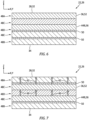
- the microwave source 40 During operation of the thermal anti-icing system 24 of FIG. 1 , the microwave source 40 generates microwaves. These microwaves are received by the downstream waveguide 44B through the upstream waveguide 44A. Referring to FIG. 7 , the downstream waveguide 44B directs the received microwaves 60 in a first vertical direction towards / to the susceptor 36 through one or more other layers 48 of the exterior skin 26. These transmitted microwaves 60 impinge against and are absorbed by the susceptor 36, and are then transformed by the susceptor 36 into thermal energy 62. This thermal energy 62 may be transferred via conduction from the susceptor 36 into a region of the aircraft structure exterior skin 26 adjacent and/or proximate the susceptor 36. This transfer of the thermal energy 62 may heat the region of the exterior surface 28, 32 and thereby melt and/or prevent ice accumulation over and/or about the aircraft structure exterior skin region.
- the reflector 66 may be configured as a layer (or strip) of material.
- This reflector material may be metal such as, but not limited to, indium tin oxide (ITO).
- ITO indium tin oxide
- the reflector material has a conductance of less than one ohm-per-square inch (1 ⁇ /in 2 ).
- the present disclosure is not limited to the foregoing exemplary reflector materials or reflector conductance.
- the reflector 66 of FIG. 8 is configured with the aircraft structure 22 and its exterior skin 26.
- the reflector 66 of FIG. 8 for example, is integrated into the exterior skin 26 vertically between the skin exterior surface 32 and the skin interior surface 34, where the reflector 66 is typically vertically between the downstream waveguide 44B and the skin interior surface 34.
- the exterior skin 26 of FIG. 8 may have a similar construction as the exterior skin 26 of FIG. 2 .
- the exterior skin 26 of FIG. 8 further includes one or more addition intermediate skin layers 48F and 48G (also generally referred to as "48").
- At least one of the intermediate skin layers (e.g., 48G) may at least partially or completely form the reflector 66.
- the intermediate skin layer 48G of FIG. 8 forms the reflector 66.
- the intermediate skin layer 48G of FIG. 8 is (or otherwise includes) the layer of reflector material that forms the reflector 66.
- the reflector 66 may be located within the exterior skin 26 at (e.g., on, adjacent or proximate) the skin interior surface 34.
- this intermediate skin layer 48G that forms the reflector 66 may be referred to below as a reflector layer 68.
- the reflector 66 of FIG. 8 is configured to laterally overlap (along the x-axis and/or the y-axis) the entirety of the aircraft structure 22, the exterior skin 26, the exterior surface 28, 32 and/or one or more other thermal anti-icing system components 36 and 44B.
- the reflector 66 may extend along the entire lateral extent of the exterior surface 28, 32.
- the reflector 66 may laterally overlap (along the x-axis and/or the y-axis) a select portion of the exterior surface 28, 32. For example, referring to FIG.
- the remaining skin layer 48F may be configured as a structural layer, a support layer and/or a filler layer.
- the remaining (e.g., intra-reflector-waveguide) intermediate skin layer 48F may be configured as a layer of the adhesive 50 / the matrix material.
- the intermediate skin layer 48F may alternatively be configured as a thin sheet of the reinforcement material embedded within (or otherwise arranged with) the matrix. The present disclosure, however, is not limited to the foregoing exemplary reinforcement or matrix materials.
- the reflector layer 68 vertical thickness may be equal to or different (e.g., less or greater) than the vertical thicknesses of any one or more of the remaining skin layers 48.
- each of the thermal anti-icing system components 36, 44B and 66 may be formed by or otherwise includes in a discrete one of the skin layers 48 of the exterior skin 26; e.g., see FIGS. 2 and 8 .
- two or more of the thermal anti-icing system components e.g., 36 and 44B
- At least one downstream waveguide 44B and one or more of the susceptors 36 (or susceptor segments 54) of FIG. 11 are all arranged in the same intermediate skin layer 48C.
- the downstream waveguide 44B and the susceptors 36 are vertically aligned / vertically overlap within the exterior skin 26. However, the downstream waveguide 44B is laterally displaced from each of the susceptors 36.
- the downstream waveguide 44B of FIG. 11 for example, is laterally separated from the susceptors 36 by microwave transparent material; e.g., the adhesive 50, the matrix, etc.
- the downstream waveguide 44B of FIG. 11 is also located laterally between the susceptors 36.
- various other arrangements of the thermal anti-icing system components within the exterior skin 26 are possible and contemplated by the present disclosure.
- the microwave source 40 of FIG. 1 may be tuned to an absorption frequency of the susceptor 36. This may facilitate provision of higher electromagnetic radiation frequencies, while reducing a footprint of the electromagnetic radiation.
- the microwave source 40 may be tuned for a V-band frequency between forty gigahertz and eighty gigahertz; e.g., between 60 GHz and 77 GHz. Within such a frequency range, absorption by other aircraft structure materials is relatively low and the susceptor 36 may be made relatively small.
- the susceptor 36 for example, may be about 1.25 mm thick for a microwave transmission frequency of about 60 GHz.
- the present disclosure is not limited to the forgoing exemplary frequencies or sizes.
- the thermal anti-icing system 24 of the present disclosure is also relatively resistant to foreign object damage (FOD).
- FOD foreign object damage
- the aircraft structure 22 of FIG. 1 may be subject to a foreign object impact.
- such an impact may crack and/or fracture, inter alia, the susceptor 36; e.g., material within the susceptor layer 52 (e.g., see FIG. 2 ).
- the susceptor 36 may still be operable to transform the microwaves into heat energy since no electrical interconnection within the susceptor 36 is required.
- provision of the relatively light weight susceptor(s) 36 and waveguide(s) 48, 48B may reduce aircraft weight by obviating the need for ducting and valve associated with a traditional forced hot air anti-icing system.
- FIG. 12 illustrates an inlet structure 72 of a nacelle for an aircraft propulsion system; e.g., a turbofan or a turbojet propulsion system.
- This inlet structure 72 includes an inlet lip 74, an inner barrel 76 and an outer barrel 78.
- the inlet lip 74 forms a leading edge 80 of the inlet structure 72.
- the inner barrel 76 is connected to a radial inner end 82 of the inlet lip 74, and at least partially forms an outer peripheral boundary of an inlet duct 84 into the aircraft propulsion system.
- the outer barrel 78 is connected to a radial outer end 86 of the inlet lip 74, and circumscribes the inner barrel 76.
- the inlet structure 72 of FIG. 12 is configured with the exterior skin 26.
- This exterior skin 26 may form at least an inner portion of the inlet lip 74.
- the exterior skin 26 of FIG. 12 extends axially along an axial centerline 88 of the aircraft propulsion system from (or about) the leading edge 80 to (or towards) the radial inner end 82 of the inlet lip 74.
- the exterior skin 26 may also extend axially along the axial centerline 88 from (or about) the leading edge 80 to (or towards) the radial outer end 86 of the inlet lip 74.
- the exterior skin 26 extends circumferentially about (e.g., completely around) the axial centerline 88.
- the inlet structure 72 may be configured with a plurality of the exterior skins 26, where each exterior skin 26 forms an arcuate segment of the inlet lip 74.
- the exterior skin 26 and the thermal anti-icing system 24 is described above as being configured with the inlet structure 72, the present disclosure is not limited to such an exemplary application. Rather, the exterior skin 26 and the thermal anti-icing system 24 of the present disclosure may be configured with any aircraft structure which would benefit from including de-icing capability. Furthermore, the exterior skin 26 and the thermal anti-icing system 24 of the present disclosure may alternatively be configured for non-aircraft applications.
- the exterior skin 26 may form an exterior surface of an airfoil such as, but not limited to, a wind turbine blade.
- the exterior skin 26 may for an exterior surface of another type of vehicle that would benefit from anti-icing; e.g., an automobile, a boat, etc.
Landscapes
- Engineering & Computer Science (AREA)
- Aviation & Aerospace Engineering (AREA)
- Physics & Mathematics (AREA)
- Electromagnetism (AREA)
- Chemical & Material Sciences (AREA)
- Combustion & Propulsion (AREA)
- Laminated Bodies (AREA)
- Constitution Of High-Frequency Heating (AREA)
Claims (13)
- Ensemble (20) pour une structure, comprenant :un revêtement composite (26) se prolongeant entre une surface extérieure (28) et une surface intérieure (34) ; etun système antigivrage thermique (24) comprenant un suscepteur (36) et un guide d'ondes, le suscepteur (36) et le guide d'ondes (44A, 44B) étant intégrés dans le revêtement composite (26) entre la surface extérieure (28) et la surface intérieure (34), et le guide d'ondes (44A, 44B) étant configuré pour diriger des micro-ondes vers le suscepteur (36) pour faire fondre la glace et/ou empêcher l'accumulation de celle-ci sur la surface extérieure (28).
- Ensemble (20) selon une quelconque revendication précédente, dans lequel le revêtement composite (26) se prolonge entre la surface extérieure (28) et la surface intérieure (34) sans interruption.
- Ensemble (20) selon une quelconque revendication précédente, dans lequel le suscepteur (36) est agencé entre le guide d'ondes (44A, 44B) et la surface extérieure (28).
- Ensemble (20) selon une quelconque revendication précédente, dans lequelle revêtement composite (26) comprend une première couche, une deuxième couche et une troisième couche entre la première couche et la deuxième couche ;la première couche comprend le suscepteur (36) ; etla deuxième couche comprend le guide d'ondes (44A, 44B).
- Ensemble (20) selon la revendication 4, dans lequel la troisième couche comprend un matériau transparent aux micro-ondes.
- Ensemble (20) selon une quelconque revendication précédente, dans lequelle revêtement composite (26) comprend une pluralité de couches ; une première couche de la pluralité de couches comprend le suscepteur (36) et le guide d'ondes (44A, 44B) ; etle guide d'ondes (44A, 44B) est espacé latéralement du suscepteur (36) à l'intérieur de la première de la pluralité de couches, dans lequel une seconde couche de la pluralité de couches comprend éventuellement un matériau transparent aux micro-ondes.
- Ensemble (20) selon une quelconque revendication précédente, dans lequel au moins l'un du suscepteur (36) ou du guide d'ondes (44A, 44B) comprend du métal.
- Ensemble (20) selon une quelconque revendication précédente, dans lequel le suscepteur (36) comprend un renfort en fibres dans une matrice polymère.
- Ensemble (20) selon une quelconque revendication précédente, dans lequel le système antigivrage thermique (24) comprend également un réflecteur (66) configuré pour réfléchir les micro-ondes s'éloignant du suscepteur (36) et de la surface extérieure (28) vers le suscepteur (36), dans lequel le réflecteur (66) comprend éventuellement du métal.
- Ensemble (20) selon la revendication 9, dans lequel :le réflecteur (66) est intégré dans le revêtement composite (26) entre la surface extérieure (28) et la surface intérieure (34) ; oule réflecteur (66) est agencé entre la surface intérieure (34) et le guide d'ondes (44A, 44B).
- Ensemble (20) selon une quelconque revendication précédente, dans lequel :les micro-ondes sont émises à une fréquence comprise entre un gigahertz (1 GHz) et dix gigahertz (10 GHz) ; oules micro-ondes sont émises à une fréquence comprise entre quarante gigahertz (40 GHz) et quatre-vingts gigahertz (80 GHz) .
- Ensemble (20) selon l'une quelconque des revendications 1 à 10, dans lequel :les micro-ondes sont émises à une fréquence comprise entre vingt gigahertz (20 GHz) et vingt-cinq gigahertz (25 GHz) ; oules micro-ondes sont émises à une fréquence comprise entre cent cinquante gigahertz (150 GHz) et deux cents gigahertz (200 GHz).
- Ensemble (20) selon une quelconque revendication précédente, comprenant également :une structure d'entrée de nacelle pour un système de propulsion d'aéronef ;la structure d'entrée de nacelle comprenant le revêtement composite (26).
Priority Applications (1)
| Application Number | Priority Date | Filing Date | Title |
|---|---|---|---|
| EP25150364.5A EP4520665A3 (fr) | 2021-06-30 | 2022-06-30 | Système d'antigivrage thermique à micro-ondes intégré |
Applications Claiming Priority (1)
| Application Number | Priority Date | Filing Date | Title |
|---|---|---|---|
| US17/363,409 US12017779B2 (en) | 2021-06-30 | 2021-06-30 | Integrated microwave thermal anti-icing system |
Related Child Applications (1)
| Application Number | Title | Priority Date | Filing Date |
|---|---|---|---|
| EP25150364.5A Division EP4520665A3 (fr) | 2021-06-30 | 2022-06-30 | Système d'antigivrage thermique à micro-ondes intégré |
Publications (2)
| Publication Number | Publication Date |
|---|---|
| EP4112448A1 EP4112448A1 (fr) | 2023-01-04 |
| EP4112448B1 true EP4112448B1 (fr) | 2025-01-08 |
Family
ID=82493923
Family Applications (2)
| Application Number | Title | Priority Date | Filing Date |
|---|---|---|---|
| EP22182402.2A Active EP4112448B1 (fr) | 2021-06-30 | 2022-06-30 | Système antigivrage thermique intégré à micro-ondes |
| EP25150364.5A Pending EP4520665A3 (fr) | 2021-06-30 | 2022-06-30 | Système d'antigivrage thermique à micro-ondes intégré |
Family Applications After (1)
| Application Number | Title | Priority Date | Filing Date |
|---|---|---|---|
| EP25150364.5A Pending EP4520665A3 (fr) | 2021-06-30 | 2022-06-30 | Système d'antigivrage thermique à micro-ondes intégré |
Country Status (2)
| Country | Link |
|---|---|
| US (1) | US12017779B2 (fr) |
| EP (2) | EP4112448B1 (fr) |
Families Citing this family (1)
| Publication number | Priority date | Publication date | Assignee | Title |
|---|---|---|---|---|
| US12384546B2 (en) * | 2023-10-02 | 2025-08-12 | The Boeing Company | Ice protection system for a truss-braced wing of an aircraft |
Citations (1)
| Publication number | Priority date | Publication date | Assignee | Title |
|---|---|---|---|---|
| EP2915748A1 (fr) * | 2014-03-03 | 2015-09-09 | The Boeing Company | Systèmes et procédés pour deceler la formation de glace ainsi que pour effectuer le degivrage |
Family Cites Families (36)
| Publication number | Priority date | Publication date | Assignee | Title |
|---|---|---|---|---|
| US4060212A (en) * | 1976-04-01 | 1977-11-29 | System Development Corporation | Deicing apparatus and method |
| US4365131A (en) * | 1980-06-27 | 1982-12-21 | Hansman Jr Robert J | Microwave ice prevention system |
| EP0350249A3 (fr) * | 1988-07-04 | 1991-05-22 | Beckett Industries Inc. | Structure laminée et procédé de chauffage |
| US5061836A (en) | 1990-01-18 | 1991-10-29 | United Technologies Corporation | Microwave deicing for aircraft engine propulsor blades |
| US5248864A (en) * | 1991-07-30 | 1993-09-28 | E. I. Du Pont De Nemours And Company | Method for induction heating of composite materials |
| US5391430A (en) * | 1992-06-23 | 1995-02-21 | Aluminum Company Of America | Thermostating foil-based laminate microwave absorbers |
| US5553815A (en) * | 1994-04-07 | 1996-09-10 | The B. F. Goodrich Company | De-icer adapted for installment on the inner surface of a structural member |
| FR2723761B1 (fr) | 1994-08-18 | 1996-09-20 | Snecma | Turboreacteur equipe d'un systeme de degivrage sur le carter d'entree |
| US5615849A (en) * | 1995-04-14 | 1997-04-01 | Salisbury; Jonathan T. | Microwave deicing and anti-icing system for aircraft |
| CA2227526A1 (fr) * | 1997-01-21 | 1998-07-21 | Michael J. Giamati | Systeme de degivrage hybride avec commande sequentielle d'element |
| DE19750198C2 (de) * | 1997-11-13 | 1999-10-21 | Karlsruhe Forschzent | Enteisung von Flugzeugen mit Mikrowellen |
| US6790526B2 (en) * | 1998-01-30 | 2004-09-14 | Integument Technologies, Inc. | Oxyhalopolymer protective multifunctional appliqués and paint replacement films |
| DE10016259C2 (de) | 2000-04-03 | 2002-06-20 | Karlsruhe Forschzent | Kompakte millimeterwellentechnische Einrichtung zum Enteisen und/oder Vorbeugeneiner Vereisung |
| DE10016261C2 (de) * | 2000-04-03 | 2002-08-29 | Karlsruhe Forschzent | Kompakte mikrowellentechnische Einrichtung zum Enteisen oder Vorbeugen einer Vereisung |
| DE10118121A1 (de) * | 2001-04-11 | 2002-10-24 | Karlsruhe Forschzent | Mikrowellentechnische Einrichtung zur Eisfreihaltung und Enteisung formstabiler Hohlkörper-Strukturen an der Oberfläche und Verfahren zum Betreiben der Einrichtung |
| US6664520B2 (en) * | 2001-05-21 | 2003-12-16 | Thermal Solutions, Inc. | Thermal seat and thermal device dispensing and vending system employing RFID-based induction heating devices |
| US7137596B2 (en) * | 2002-05-31 | 2006-11-21 | The Boeing Company | Aircraft surface ice inhibitor |
| US7323666B2 (en) * | 2003-12-08 | 2008-01-29 | Saint-Gobain Performance Plastics Corporation | Inductively heatable components |
| US7425296B2 (en) * | 2004-12-03 | 2008-09-16 | Pressco Technology Inc. | Method and system for wavelength specific thermal irradiation and treatment |
| FR2906786B1 (fr) * | 2006-10-09 | 2009-11-27 | Eurocopter France | Procede et dispositif de degivrage d'une paroi d'aeronef |
| FR2943040B1 (fr) * | 2009-03-13 | 2012-08-31 | Sagem Defense Securite | Ensemble moteur et nacelle pour aeronef, equipe d'un dispositif anti-glace |
| US9469408B1 (en) * | 2009-09-03 | 2016-10-18 | The Boeing Company | Ice protection system and method |
| US8505273B2 (en) * | 2009-11-03 | 2013-08-13 | General Electric Company | System for ice and/or frost prevention using guided wave energy |
| US20120196453A1 (en) * | 2011-02-01 | 2012-08-02 | Arizona Board Of Regents For And On Behalf Of Arizona State University | Systems and Methods for Susceptor Assisted Microwave Annealing |
| US9056684B2 (en) * | 2011-04-08 | 2015-06-16 | Textron Innovations Inc. | Rotor blade de-icing system |
| US20150083863A1 (en) * | 2012-05-16 | 2015-03-26 | Jka Kemi Ab | Deicing of a surface of structures in general such as wind turbine blades, aircraft wings using induction or radiation |
| US9638044B2 (en) * | 2014-03-11 | 2017-05-02 | Hamilton Sundstrand Corporation | Resistive-inductive propeller blade de-icing system including contactless power supply |
| US10442523B2 (en) * | 2015-08-25 | 2019-10-15 | The Boeing Company | Synergetic noise absorption and anti-icing for aircrafts |
| ES2681658T3 (es) * | 2015-10-05 | 2018-09-14 | Airbus Defence And Space, S.A. | Dispositivo y método de protección contra el hielo |
| FR3069883B1 (fr) * | 2017-08-03 | 2019-06-28 | Airbus Operations | Aile comportant un bord d'attaque presentant des moyens pour prevenir le depot de residus |
| FR3072649B1 (fr) | 2017-10-20 | 2019-11-08 | Airbus Operations | Systeme de protection contre le givre pour nacelle de moteur d'aeronef |
| US11242150B2 (en) * | 2018-06-22 | 2022-02-08 | General Electric Company | Anti-icing system for an aircraft |
| CN109050938B (zh) | 2018-08-14 | 2022-02-08 | 中国电子科技集团公司第三十八研究所 | 一种飞机微波除冰装置 |
| FR3096658B1 (fr) * | 2019-05-27 | 2022-10-28 | Safran Nacelles | Lèvre d’entrée d’air d’une nacelle de turbomachine d’aéronef comportant un dispositif de dégivrage par émission de micro-ondes. |
| US20210129997A1 (en) * | 2019-11-05 | 2021-05-06 | Rohr, Inc. | Thermal anti-icing system with microwave system |
| US20220361300A1 (en) * | 2021-05-10 | 2022-11-10 | The Boeing Company | Induction-heating system including a susceptor for generating induction heating below a selected curie temperature |
-
2021
- 2021-06-30 US US17/363,409 patent/US12017779B2/en active Active
-
2022
- 2022-06-30 EP EP22182402.2A patent/EP4112448B1/fr active Active
- 2022-06-30 EP EP25150364.5A patent/EP4520665A3/fr active Pending
Patent Citations (1)
| Publication number | Priority date | Publication date | Assignee | Title |
|---|---|---|---|---|
| EP2915748A1 (fr) * | 2014-03-03 | 2015-09-09 | The Boeing Company | Systèmes et procédés pour deceler la formation de glace ainsi que pour effectuer le degivrage |
Also Published As
| Publication number | Publication date |
|---|---|
| US12017779B2 (en) | 2024-06-25 |
| US20230002064A1 (en) | 2023-01-05 |
| EP4112448A1 (fr) | 2023-01-04 |
| EP4520665A2 (fr) | 2025-03-12 |
| EP4520665A3 (fr) | 2025-05-07 |
Similar Documents
| Publication | Publication Date | Title |
|---|---|---|
| EP4112449B1 (fr) | Système antigivrage thermique à micro-ondes pour structure acoustique d'aéronef | |
| US11338933B2 (en) | Acoustic honeycomb panel with integrated electrical heater | |
| US6207940B1 (en) | Microwave de-icing system for aircrafts | |
| EP2354494B1 (fr) | Nacelle et système d'antigivrage de turbomachine et son procédé | |
| CN110723294B (zh) | 飞机防冰系统及其制造方法 | |
| US6642490B2 (en) | Compact millimeterwave system for De-icing and for preventing the formation of ice on the outer surfaces of shell structures exposed to meterological influences | |
| US20130009846A1 (en) | Insert for radomes and methods of manufacturing insert for radomes | |
| US20030015524A1 (en) | Compact microwave system for de-icing and for preventing icing of the outer surfaces of hollow or shell structures which are exposed to meterological influences | |
| EP3819220B1 (fr) | Système antigivrage thermique comprenant un système à micro-ondes | |
| EP4112448B1 (fr) | Système antigivrage thermique intégré à micro-ondes | |
| US12009590B2 (en) | Cover for a vehicle, in particular for a supersonic or hypersonic vehicle | |
| US20190389589A1 (en) | Anti-icing system for an aircraft | |
| EP3845457B1 (fr) | Système antigivrage thermique comprenant un système à micro-ondes | |
| US20250149781A1 (en) | Radome with Ceramic Matrix Composite | |
| EP2232626A1 (fr) | Procédés et appareil pour une fenêtre d'onde millimétrique multicouche | |
| CN116238694A (zh) | 一种透波防除冰功能复合结构 | |
| EP4538179A1 (fr) | Système de protection contre la glace pour un aéronef | |
| JP3899858B2 (ja) | 飛しょう体用レドーム | |
| RU2316088C1 (ru) | Антенный обтекатель летательного аппарата | |
| US20250229906A1 (en) | Laminate Structure with Integrated Power Distribution | |
| GB2544585A (en) | Heating system for electrothermal temperature control, and method for the production of said heating system |
Legal Events
| Date | Code | Title | Description |
|---|---|---|---|
| PUAI | Public reference made under article 153(3) epc to a published international application that has entered the european phase |
Free format text: ORIGINAL CODE: 0009012 |
|
| STAA | Information on the status of an ep patent application or granted ep patent |
Free format text: STATUS: THE APPLICATION HAS BEEN PUBLISHED |
|
| AK | Designated contracting states |
Kind code of ref document: A1 Designated state(s): AL AT BE BG CH CY CZ DE DK EE ES FI FR GB GR HR HU IE IS IT LI LT LU LV MC MK MT NL NO PL PT RO RS SE SI SK SM TR |
|
| STAA | Information on the status of an ep patent application or granted ep patent |
Free format text: STATUS: REQUEST FOR EXAMINATION WAS MADE |
|
| 17P | Request for examination filed |
Effective date: 20230703 |
|
| RBV | Designated contracting states (corrected) |
Designated state(s): AL AT BE BG CH CY CZ DE DK EE ES FI FR GB GR HR HU IE IS IT LI LT LU LV MC MK MT NL NO PL PT RO RS SE SI SK SM TR |
|
| GRAP | Despatch of communication of intention to grant a patent |
Free format text: ORIGINAL CODE: EPIDOSNIGR1 |
|
| STAA | Information on the status of an ep patent application or granted ep patent |
Free format text: STATUS: GRANT OF PATENT IS INTENDED |
|
| INTG | Intention to grant announced |
Effective date: 20240802 |
|
| GRAS | Grant fee paid |
Free format text: ORIGINAL CODE: EPIDOSNIGR3 |
|
| GRAA | (expected) grant |
Free format text: ORIGINAL CODE: 0009210 |
|
| STAA | Information on the status of an ep patent application or granted ep patent |
Free format text: STATUS: THE PATENT HAS BEEN GRANTED |
|
| AK | Designated contracting states |
Kind code of ref document: B1 Designated state(s): AL AT BE BG CH CY CZ DE DK EE ES FI FR GB GR HR HU IE IS IT LI LT LU LV MC MK MT NL NO PL PT RO RS SE SI SK SM TR |
|
| REG | Reference to a national code |
Ref country code: GB Ref legal event code: FG4D |
|
| REG | Reference to a national code |
Ref country code: CH Ref legal event code: EP |
|
| REG | Reference to a national code |
Ref country code: DE Ref legal event code: R096 Ref document number: 602022009509 Country of ref document: DE |
|
| REG | Reference to a national code |
Ref country code: IE Ref legal event code: FG4D |
|
| REG | Reference to a national code |
Ref country code: LT Ref legal event code: MG9D |
|
| REG | Reference to a national code |
Ref country code: NL Ref legal event code: MP Effective date: 20250108 |
|
| REG | Reference to a national code |
Ref country code: AT Ref legal event code: MK05 Ref document number: 1758172 Country of ref document: AT Kind code of ref document: T Effective date: 20250108 |
|
| PG25 | Lapsed in a contracting state [announced via postgrant information from national office to epo] |
Ref country code: NL Free format text: LAPSE BECAUSE OF FAILURE TO SUBMIT A TRANSLATION OF THE DESCRIPTION OR TO PAY THE FEE WITHIN THE PRESCRIBED TIME-LIMIT Effective date: 20250108 |
|
| PG25 | Lapsed in a contracting state [announced via postgrant information from national office to epo] |
Ref country code: RS Free format text: LAPSE BECAUSE OF FAILURE TO SUBMIT A TRANSLATION OF THE DESCRIPTION OR TO PAY THE FEE WITHIN THE PRESCRIBED TIME-LIMIT Effective date: 20250408 |
|
| PG25 | Lapsed in a contracting state [announced via postgrant information from national office to epo] |
Ref country code: PL Free format text: LAPSE BECAUSE OF FAILURE TO SUBMIT A TRANSLATION OF THE DESCRIPTION OR TO PAY THE FEE WITHIN THE PRESCRIBED TIME-LIMIT Effective date: 20250108 |
|
| PGFP | Annual fee paid to national office [announced via postgrant information from national office to epo] |
Ref country code: DE Payment date: 20250520 Year of fee payment: 4 |
|
| PG25 | Lapsed in a contracting state [announced via postgrant information from national office to epo] |
Ref country code: ES Free format text: LAPSE BECAUSE OF FAILURE TO SUBMIT A TRANSLATION OF THE DESCRIPTION OR TO PAY THE FEE WITHIN THE PRESCRIBED TIME-LIMIT Effective date: 20250108 |
|
| PG25 | Lapsed in a contracting state [announced via postgrant information from national office to epo] |
Ref country code: NO Free format text: LAPSE BECAUSE OF FAILURE TO SUBMIT A TRANSLATION OF THE DESCRIPTION OR TO PAY THE FEE WITHIN THE PRESCRIBED TIME-LIMIT Effective date: 20250408 Ref country code: IS Free format text: LAPSE BECAUSE OF FAILURE TO SUBMIT A TRANSLATION OF THE DESCRIPTION OR TO PAY THE FEE WITHIN THE PRESCRIBED TIME-LIMIT Effective date: 20250508 |
|
| PG25 | Lapsed in a contracting state [announced via postgrant information from national office to epo] |
Ref country code: HR Free format text: LAPSE BECAUSE OF FAILURE TO SUBMIT A TRANSLATION OF THE DESCRIPTION OR TO PAY THE FEE WITHIN THE PRESCRIBED TIME-LIMIT Effective date: 20250108 |
|
| PG25 | Lapsed in a contracting state [announced via postgrant information from national office to epo] |
Ref country code: PT Free format text: LAPSE BECAUSE OF FAILURE TO SUBMIT A TRANSLATION OF THE DESCRIPTION OR TO PAY THE FEE WITHIN THE PRESCRIBED TIME-LIMIT Effective date: 20250508 Ref country code: LV Free format text: LAPSE BECAUSE OF FAILURE TO SUBMIT A TRANSLATION OF THE DESCRIPTION OR TO PAY THE FEE WITHIN THE PRESCRIBED TIME-LIMIT Effective date: 20250108 |
|
| PGFP | Annual fee paid to national office [announced via postgrant information from national office to epo] |
Ref country code: FR Payment date: 20250521 Year of fee payment: 4 |
|
| PG25 | Lapsed in a contracting state [announced via postgrant information from national office to epo] |
Ref country code: GR Free format text: LAPSE BECAUSE OF FAILURE TO SUBMIT A TRANSLATION OF THE DESCRIPTION OR TO PAY THE FEE WITHIN THE PRESCRIBED TIME-LIMIT Effective date: 20250409 Ref country code: BG Free format text: LAPSE BECAUSE OF FAILURE TO SUBMIT A TRANSLATION OF THE DESCRIPTION OR TO PAY THE FEE WITHIN THE PRESCRIBED TIME-LIMIT Effective date: 20250108 |
|
| PG25 | Lapsed in a contracting state [announced via postgrant information from national office to epo] |
Ref country code: AT Free format text: LAPSE BECAUSE OF FAILURE TO SUBMIT A TRANSLATION OF THE DESCRIPTION OR TO PAY THE FEE WITHIN THE PRESCRIBED TIME-LIMIT Effective date: 20250108 |
|
| PG25 | Lapsed in a contracting state [announced via postgrant information from national office to epo] |
Ref country code: SE Free format text: LAPSE BECAUSE OF FAILURE TO SUBMIT A TRANSLATION OF THE DESCRIPTION OR TO PAY THE FEE WITHIN THE PRESCRIBED TIME-LIMIT Effective date: 20250108 |
|
| PG25 | Lapsed in a contracting state [announced via postgrant information from national office to epo] |
Ref country code: SM Free format text: LAPSE BECAUSE OF FAILURE TO SUBMIT A TRANSLATION OF THE DESCRIPTION OR TO PAY THE FEE WITHIN THE PRESCRIBED TIME-LIMIT Effective date: 20250108 |
|
| REG | Reference to a national code |
Ref country code: DE Ref legal event code: R097 Ref document number: 602022009509 Country of ref document: DE |
|
| PG25 | Lapsed in a contracting state [announced via postgrant information from national office to epo] |
Ref country code: DK Free format text: LAPSE BECAUSE OF FAILURE TO SUBMIT A TRANSLATION OF THE DESCRIPTION OR TO PAY THE FEE WITHIN THE PRESCRIBED TIME-LIMIT Effective date: 20250108 |
|
| PG25 | Lapsed in a contracting state [announced via postgrant information from national office to epo] |
Ref country code: CZ Free format text: LAPSE BECAUSE OF FAILURE TO SUBMIT A TRANSLATION OF THE DESCRIPTION OR TO PAY THE FEE WITHIN THE PRESCRIBED TIME-LIMIT Effective date: 20250108 Ref country code: EE Free format text: LAPSE BECAUSE OF FAILURE TO SUBMIT A TRANSLATION OF THE DESCRIPTION OR TO PAY THE FEE WITHIN THE PRESCRIBED TIME-LIMIT Effective date: 20250108 |
|
| PG25 | Lapsed in a contracting state [announced via postgrant information from national office to epo] |
Ref country code: RO Free format text: LAPSE BECAUSE OF FAILURE TO SUBMIT A TRANSLATION OF THE DESCRIPTION OR TO PAY THE FEE WITHIN THE PRESCRIBED TIME-LIMIT Effective date: 20250108 |
|
| PG25 | Lapsed in a contracting state [announced via postgrant information from national office to epo] |
Ref country code: SK Free format text: LAPSE BECAUSE OF FAILURE TO SUBMIT A TRANSLATION OF THE DESCRIPTION OR TO PAY THE FEE WITHIN THE PRESCRIBED TIME-LIMIT Effective date: 20250108 |
|
| PLBE | No opposition filed within time limit |
Free format text: ORIGINAL CODE: 0009261 |
|
| STAA | Information on the status of an ep patent application or granted ep patent |
Free format text: STATUS: NO OPPOSITION FILED WITHIN TIME LIMIT |
|
| REG | Reference to a national code |
Ref country code: CH Ref legal event code: L10 Free format text: ST27 STATUS EVENT CODE: U-0-0-L10-L00 (AS PROVIDED BY THE NATIONAL OFFICE) Effective date: 20251119 |
|
| 26N | No opposition filed |
Effective date: 20251009 |
|
| REG | Reference to a national code |
Ref country code: CH Ref legal event code: H13 Free format text: ST27 STATUS EVENT CODE: U-0-0-H10-H13 (AS PROVIDED BY THE NATIONAL OFFICE) Effective date: 20260127 |
|
| PG25 | Lapsed in a contracting state [announced via postgrant information from national office to epo] |
Ref country code: IT Free format text: LAPSE BECAUSE OF FAILURE TO SUBMIT A TRANSLATION OF THE DESCRIPTION OR TO PAY THE FEE WITHIN THE PRESCRIBED TIME-LIMIT Effective date: 20250108 |
|
| PG25 | Lapsed in a contracting state [announced via postgrant information from national office to epo] |
Ref country code: MC Free format text: LAPSE BECAUSE OF FAILURE TO SUBMIT A TRANSLATION OF THE DESCRIPTION OR TO PAY THE FEE WITHIN THE PRESCRIBED TIME-LIMIT Effective date: 20250108 |
|
| PG25 | Lapsed in a contracting state [announced via postgrant information from national office to epo] |
Ref country code: LU Free format text: LAPSE BECAUSE OF NON-PAYMENT OF DUE FEES Effective date: 20250630 |
|
| REG | Reference to a national code |
Ref country code: BE Ref legal event code: MM Effective date: 20250630 |
|
| PG25 | Lapsed in a contracting state [announced via postgrant information from national office to epo] |
Ref country code: IE Free format text: LAPSE BECAUSE OF NON-PAYMENT OF DUE FEES Effective date: 20250630 |
|
| PG25 | Lapsed in a contracting state [announced via postgrant information from national office to epo] |
Ref country code: BE Free format text: LAPSE BECAUSE OF NON-PAYMENT OF DUE FEES Effective date: 20250630 |
|
| PG25 | Lapsed in a contracting state [announced via postgrant information from national office to epo] |
Ref country code: CH Free format text: LAPSE BECAUSE OF NON-PAYMENT OF DUE FEES Effective date: 20250630 |