EP4112467B1 - Agencement de rail de montage pour un plancher d'aéronef, structure de plancher et aéronef en étant équipé - Google Patents
Agencement de rail de montage pour un plancher d'aéronef, structure de plancher et aéronef en étant équipé Download PDFInfo
- Publication number
- EP4112467B1 EP4112467B1 EP21182985.8A EP21182985A EP4112467B1 EP 4112467 B1 EP4112467 B1 EP 4112467B1 EP 21182985 A EP21182985 A EP 21182985A EP 4112467 B1 EP4112467 B1 EP 4112467B1
- Authority
- EP
- European Patent Office
- Prior art keywords
- mounting
- mounting rail
- bolt
- rail arrangement
- aircraft
- Prior art date
- Legal status (The legal status is an assumption and is not a legal conclusion. Google has not performed a legal analysis and makes no representation as to the accuracy of the status listed.)
- Active
Links
Images


Classifications
-
- B—PERFORMING OPERATIONS; TRANSPORTING
- B64—AIRCRAFT; AVIATION; COSMONAUTICS
- B64C—AEROPLANES; HELICOPTERS
- B64C1/00—Fuselages; Constructional features common to fuselages, wings, stabilising surfaces or the like
- B64C1/18—Floors
-
- B—PERFORMING OPERATIONS; TRANSPORTING
- B64—AIRCRAFT; AVIATION; COSMONAUTICS
- B64C—AEROPLANES; HELICOPTERS
- B64C1/00—Fuselages; Constructional features common to fuselages, wings, stabilising surfaces or the like
- B64C1/18—Floors
- B64C1/20—Floors specially adapted for freight
-
- B—PERFORMING OPERATIONS; TRANSPORTING
- B64—AIRCRAFT; AVIATION; COSMONAUTICS
- B64D—EQUIPMENT FOR FITTING IN OR TO AIRCRAFT; FLIGHT SUITS; PARACHUTES; ARRANGEMENT OR MOUNTING OF POWER PLANTS OR PROPULSION TRANSMISSIONS IN AIRCRAFT
- B64D11/00—Passenger or crew accommodation; Flight-deck installations not otherwise provided for
- B64D11/06—Arrangements of seats, or adaptations or details specially adapted for aircraft seats
- B64D11/0696—Means for fastening seats to floors, e.g. to floor rails
Definitions
- the invention relates to a mounting rail arrangement for an aircraft floor. Furthermore, the invention relates to a floor structure for a fuselage of an aircraft and an aircraft having said floor structure.
- US 2010 / 0 108 808 A1 discloses a system for fixing.
- a fixing element is inserted into an elongated hole and turned in order to fix the parts together.
- EP 3 315 408 B1 discloses a seat rail adapter comprising two mounting parts. The mounting parts are anchored into a C-shaped channel by pivoting.
- EP 3 296 206 A1 discloses a seat movement-securing device that includes a seat rail that may be fixed to an attachment member. A locking mechanism that is securely installed on the attachment member is used to secure the attachment member to the seat rail.
- US 6 302 358 B1 discloses a system to quickly convert part of the main deck of an aircraft from a passenger transport configuration to a freight transport configuration.
- a rail system for fixing fittings in a cabin of a vehicle includes a first elongate rail body with a fixing side for fixing to a vehicle structure, an opposite support side with a support surface for receiving fittings, and a rail cross-section extending between the fixing side and the support side, and several fixing inserts which can be fixed along the support surface.
- the rail cross-section has two mutually opposing legs which are spaced apart from each other and run perpendicularly to the support surface, and the fixing inserts are configured so as not to protrude beyond the support surface.
- CN 211 399 178 U discloses a fixed frame for a textile machine.
- CN 206 029 362 U discloses a drilling fixture.
- a floor panel assembly may include a floor panel comprising a pair of opposed surfaces, wherein the floor panel includes at least one key hole slot defined in one of the opposed surfaces.
- the assembly also includes at least one seat track positioned between the opposed surfaces, wherein the seat track comprises at least one key hole slot defined therein that is substantially aligned with a respective key hole slot defined in the floor panel.
- the assembly includes at least one fastener assembly comprising a fastener configured to be positioned through a respective key hole slot defined in the floor panel and the seat track.
- EP 2 848 533 A1 discloses a mounting system for objects in a transportation means that comprises a profile rail, at least one locking device with a base body that can be brought into surface contact with a supporting surface of the profile rail and at least one locking body which is interlockable with the profile rail, as well as an actuating device with an actuating element that extends parallel to the profile rail and a clamping body that is connected to the actuating element.
- US 8 979 450 B2 discloses function elements for fixing in seat rails of aircraft.
- the function element includes a fixing rail with a web running in the x-direction and a multiplicity of extensions which protrude beyond the web in a y-direction to form a T profile.
- the the fixing rail is formed corresponding to the seat rail such that the fixing rail can be inserted in the seat rail and moved along the x-direction into a holding position in which the extensions sit between the holes below the slots, at least one fixing peg which is arranged mobile on the fixing rail and can be brought into a blocking position in which the fixing peg engages in a hole of the seat rail so that the function element is fixed in the x-direction.
- US 2018 / 0 016 009 A1 discloses a mounting apparatus for retaining aircraft monuments, the apparatus including a first support, a second support, and a joiner connecting a first end of the first support and a first end of the second support, a stay having a first end pivotably connected to the joiner, a tie rod configured to connect the joiner to an attachment point of the aircraft, a first rail having a first base configured to connect to an upper surface of the monument and a first facing configured to connect to the first support and the second support, and a second rail having a second base configured to connect to the upper surface of the monument and a second facing configured to connect to a second end of the stay.
- CN 109 110 134 A discloses an aero seat attachment device that can prevent dislocation from sliding.
- US 2020 / 0 094 970 A1 discloses systems for securing fixtures to the floor of a transportation vehicle.
- the securing system has a simplified structure comprising a securing device with two C-profiles comprising a web extending between a top plate and a bottom plate, the profiles being joined by an omega-shape fishplate. Vertical lateral walls formed by the webs of the profiles are perforated.
- EP 2 733 061 A1 discloses a fastening arrangement for attaching a floor to a support structure.
- the fastening arrangement includes a cross beam, a floor panel, a forked bolt attached to the cross beam via a barrel nut, and a lug bolt rotary connected to the fork bolt.
- the fork bolt has a head with a slit for accommodating an end of the lug bolt, such that the lug bolt is rotary in the direction of the slit.
- the head of the fork bolt is rotatable in the opening of the floor panel for screwing the fork bolt into the barrel nut by rotating the lug bolt.
- the object is achieved using the subject-matter of the independent claim.
- the invention provides a mounting rail arrangement for an aircraft floor, the mounting rail arrangement comprising a first mounting rail having a first bottom leg, a first top leg, and a first mounting portion that is arranged between the first bottom and top legs; a second mounting rail having a second bottom leg, a second top leg, and a second mounting portion that is arranged between the second bottom and top legs, wherein the first and second mounting portions face each other and define a gap therebetween, wherein the first mounting portion includes a first mounting hole and the second mounting portion includes a second mounting hole, the mounting holes being aligned to receive a mounting bolt.
- the mounting rail arrangement further comprises the mounting bolt that is inserted in the first and second mounting holes.
- the mounting bolt includes a cross hole for receiving a bolt member, e.g., the attachment bolt.
- the mounting bolt is arranged so that the cross hole is arranged within the gap so as to be accessible.
- the mounting rail arrangement further comprises an attachment bolt that is inserted in the cross hole and fixed to the mounting bolt so as to protrude above the top legs and prevent the mounting bolt from sliding out of the mounting holes.
- the first mounting rail and/or the second mounting rail is made of metal or metal alloy.
- the first mounting rail and/or the second mounting rail is made of a fiber composite material.
- the mounting rail arrangement further comprises an upper plate member attached to the top legs, the upper plate being configured for allowing protrusion of at least one bolt member.
- the mounting rail arrangement further comprises at least one floor panel that is attached to the top legs or the upper plate member.
- the invention provides a floor structure for a fuselage of an aircraft, the floor structure comprising a plurality of cross beams that are configured to horizontally extend in a direction orthogonal to a flight direction, and at least one mounting rail arrangement as disclosed above, wherein the first mounting rail and the second mounting rail are aligned parallel to the flight direction.
- the invention provides a fuselage for an aircraft, the fuselage comprising the mounting rail arrangement as disclosed above and/or a floor structure as disclosed above.
- the fuselage further comprises a monument and/or cabin attendant seats that is attached to the mounting rail arrangement and/or the floor structure.
- the invention provides an aircraft having a mounting rail arrangement as disclosed above and/or a floor structure as disclosed above and/or a fuselage as disclosed above.
- the invention is about a full floor structural decoupling for monuments and/or cabin attendant seats.
- the cabin area of a single aisle aircraft needs to be rather variable in order to satisfy the customer requirements regarding installation and arrangement of monuments, such as galley, lavatory, etc.
- HoV Head of Version
- the invention make use of the existing hard point fixation principle and provides full flexibility in x-direction by replacing the usual I-beam profile with a double C-profile.
- the double C-profile provides the hole pattern for all variants. All concepts are at least weight neutral compared to the currently use configurations. This is true in particular, if the C-profiles are made from CFRP. Further opportunity for weight reduction is identified by adding a plate for better load introduction from profile to plate and then from plate to cross beams. The double shell concept with its two plates leads to a stiff box design. Selected CFRP material cost may be compensated by higher automatization, reduced part count and non-recurring cost (NRC) (customization), fast ramp up and rate flexibility.
- NRC non-recurring cost
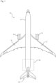
- the aft section 20 includes a passenger door 22 and a floor structure 24 that is arranged within the aft section 20.
- the floor structure 24 is supported by the fuselage 12.
- the floor structure 24 comprises a plurality of cross beams 26 that are laterally horizontally aligned.
- the cross beams 26 may be attached to a frame 27 ( Fig. 2 ).
- the floor structure 24 also comprises a plurality of support beams 28 that are attached to the cross beams 26 and vertically support the cross beams 26.
- the support beams 28 are also preferably attached to the frame 27.
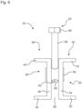
- the mounting rail arrangement 30 comprises a first mounting rail 38 and a second mounting rail 40.
- the first mounting rail 38 has a first bottom leg 42, a first top leg 44, and a first mounting portion 46.
- the first bottom leg 42 and the first top leg 44 are spaced apart from each other by the first mounting portion 46.
- the first mounting portion 46 includes a plurality of first mounting holes 48 that are distributed along the longitudinal direction of the first mounting rail 38.
- the second mounting rail 40 has a second bottom leg 50, a second top leg 52, and a second mounting portion 54.
- the second bottom leg 50 and the second top leg 52 are spaced apart from each other by the second mounting portion 54.
- the second mounting portion 54 includes a plurality of second mounting holes 56 that are distributed along the longitudinal direction of the second mounting rail 40.
- the first and second mounting rails 38, 40 are arranged such that the first and second mounting portions 46, 54 face each other.
- the first and second mounting rails 38, 40 define a gap 58 between them so that the first and second mounting portions 46, 54 are spaced apart from each other.
- the first and second mounting rails 38, 40 are arranged so that corresponding first and second mounting holes 48, 56 are aligned such that a mounting bolt (60) may pass through them.
- first and second bottom and top legs 42, 44, 50, 52 are aligned so that they may evenly support the lower or upper plate member 34, 36 or the floor panel 32.
- the mounting rail arrangement 30 comprises the mounting bolt 60 inserted into the first and second mounting holes 48, 56.
- the mounting bolt 60 includes a cross hole 62.
- the cross hole 62 is preferably formed in the center of the mounting bolt 60 and configured as a through hole.
- the cross hole 62 preferably includes threads for a preferably threaded attachment bolt (64).
- the mounting rail arrangement (30) includes two mounting rails (38, 40) having a plurality of mounting holes (48, 56) distributed along their longitudinal direction.
- a mounting bolt (60) is inserted into the mounting holes (48, 56) and an attachment bolt (64) for fixing a cabin monument and/or a cabin attendant seat is inserted into the mounting bolt (60).
- the cabin monument and/or cabin attendant seat may be installed on at different locations and/or with different orientations using all kinds of configurations enabled by the mounting holes (48, 56).
Landscapes
- Engineering & Computer Science (AREA)
- Aviation & Aerospace Engineering (AREA)
- Mechanical Engineering (AREA)
- Seats For Vehicles (AREA)
Claims (13)
- Agencement (30) de rails de montage pour un plancher d'aéronef, l'agencement (30) de rails de montage comportant un premier rail (38) de montage doté d'une première branche inférieure (42), d'une première branche supérieure (44) et d'une première partie (46) de montage qui est disposée entre les premières branches inférieure et supérieure (42, 44) ; un second rail (40) de montage doté d'une seconde branche inférieure (50), d'une seconde branche supérieure (52) et d'une seconde partie (54) de montage qui est disposée entre les secondes branches inférieure et supérieure (50, 52), les premier et second rails (38, 40) de montage étant des rails de montage distincts, les première et seconde parties (46, 54) de montage se faisant face et définissant un écartement (58) entre elles, la première partie (46) de montage comprenant un premier trou (48) de montage et la seconde partie (54) de montage comprenant un second trou (56) de montage, les trous (48, 56) de montage étant alignés pour recevoir un boulon (60) de montage,l'agencement (30) de rails de montage comportant en outre le boulon (60) de montage et un boulon (64) de fixation qui est configuré pour la fixation d'un monument de cabine et/ou de sièges pour personnel de cabine, le boulon (60) de montage étant inséré dans les premier et second trous (48, 56) de montage, le boulon (60) de montage comprenant un trou transversal (62) destiné à recevoir le boulon (64) de fixation, et le boulon (60) de montage étant disposé de telle sorte que le trou transversal (62) soit disposé à l'intérieur de l'écartement (58) de façon à être accessible,le boulon (64) de fixation étant inséré dans le trou transversal (62) et fixé au boulon (60) de montage de façon à faire saillie au-dessus des branches supérieures (44, 52) et à empêcher le boulon (60) de montage de glisser hors des trous (48, 56) de montage.
- Agencement (30) de rails de montage selon la revendication 1, le premier rail (38) de montage et/ou le second rail (40) de montage étant constitués de métal ou d'alliage métallique.
- Agencement (30) de rails de montage selon l'une quelconque des revendications précédentes, le premier rail (38) de montage et/ou le second rail (40) de montage étant constitués d'un matériau composite à fibres.
- Agencement (30) de rails de montage selon l'une quelconque des revendications précédentes, comportant en outre un élément (34) de plaque inférieure fixé aux branches inférieures (42, 50).
- Agencement (30) de rails de montage selon l'une quelconque des revendications précédentes, comportant en outre un élément (36) de plaque supérieure fixé aux branches supérieures (44, 52), l'élément (36) de plaque supérieure étant configuré pour permettre au boulon (64) de fixation de faire saillie.
- Agencement (30) de rails de montage selon l'une quelconque des revendications précédentes, comportant en outre au moins un panneau (32) de plancher qui est fixé aux branches supérieures (44, 52) ou à l'élément (36) de plaque supérieure.
- Agencement (30) de rails de montage selon l'une quelconque des revendications précédentes, la longueur hors tout du boulon (64) de fixation étant choisie de telle sorte que le boulon (64) de fixation dépasse de l'écartement (58), et, le cas échéant, du panneau (32) de plancher et/ou de l'élément (36) de plaque supérieure.
- Structure (24) de plancher pour un fuselage (12) d'un aéronef (10), la structure (24) de plancher comportant une pluralité de traverses (26) qui sont configurées pour s'étendre horizontalement dans une direction orthogonale à une direction de vol, et au moins un agencement (30) de rails de montage selon l'une quelconque des revendications précédentes, le premier rail (38) de montage et le second rail (40) de montage étant alignés parallèlement à la direction de vol.
- Structure (24) de plancher selon la revendication 8, comportant en outre une pluralité de poutres (28) d'appui qui sont fixées à au moins une des traverses (26), de façon à permettre un appui des traverses (26) sur le fuselage (12).
- Structure (24) de plancher selon l'une quelconque des revendications 8 ou 9, au moins deux agencements (30) de rails de montage étant disposés en parallèle et espacés l'un par rapport à l'autre.
- Fuselage (12) pour aéronef (10), le fuselage (12) comportant un agencement (30) de rails de montage selon l'une quelconque des revendications 1 à 7 et/ou une structure (24) de plancher selon l'une quelconque des revendications 8 à 10.
- Fuselage (12) selon la revendication 11, comportant en outre un monument et/ou un siège pour personnel de cabine qui est fixé à l'agencement (30) de rails de montage et/ou à la structure (24) de plancher.
- Aéronef (10) doté d'un agencement (30) de rails de montage selon l'une quelconque des revendications 1 à 7 et/ou d'une structure (24) de plancher selon l'une quelconque des revendications 8 à 10 et/ou d'un fuselage (12) selon la revendication 11 ou 12.
Priority Applications (2)
| Application Number | Priority Date | Filing Date | Title |
|---|---|---|---|
| EP21182985.8A EP4112467B1 (fr) | 2021-06-30 | 2021-06-30 | Agencement de rail de montage pour un plancher d'aéronef, structure de plancher et aéronef en étant équipé |
| US17/850,491 US11999463B2 (en) | 2021-06-30 | 2022-06-27 | Mounting rail arrangement for an aircraft floor, floor structure and aircraft having the same |
Applications Claiming Priority (1)
| Application Number | Priority Date | Filing Date | Title |
|---|---|---|---|
| EP21182985.8A EP4112467B1 (fr) | 2021-06-30 | 2021-06-30 | Agencement de rail de montage pour un plancher d'aéronef, structure de plancher et aéronef en étant équipé |
Publications (2)
| Publication Number | Publication Date |
|---|---|
| EP4112467A1 EP4112467A1 (fr) | 2023-01-04 |
| EP4112467B1 true EP4112467B1 (fr) | 2025-03-19 |
Family
ID=76744614
Family Applications (1)
| Application Number | Title | Priority Date | Filing Date |
|---|---|---|---|
| EP21182985.8A Active EP4112467B1 (fr) | 2021-06-30 | 2021-06-30 | Agencement de rail de montage pour un plancher d'aéronef, structure de plancher et aéronef en étant équipé |
Country Status (2)
| Country | Link |
|---|---|
| US (1) | US11999463B2 (fr) |
| EP (1) | EP4112467B1 (fr) |
Citations (1)
| Publication number | Priority date | Publication date | Assignee | Title |
|---|---|---|---|---|
| EP2733061A1 (fr) * | 2012-11-14 | 2014-05-21 | Airbus Operations GmbH | Agencement de fixation pour fixer un plancher |
Family Cites Families (14)
| Publication number | Priority date | Publication date | Assignee | Title |
|---|---|---|---|---|
| FR2745260B1 (fr) | 1996-02-28 | 1998-04-03 | Airbus Ind | Systeme et procede de conversion rapide et reversible d'un avion entre une configuration passagers et une configuration fret |
| US7775477B2 (en) * | 2006-10-25 | 2010-08-17 | The Boeing Company | Floor panel assembly, system, and associated method |
| FR2937099B1 (fr) | 2008-10-14 | 2010-12-03 | Airbus France | Systeme de fixation, destine notamment a la fixation de sieges dans un vehicule et plus particulierement dans un aeronef |
| EP2445791B1 (fr) * | 2009-06-22 | 2014-02-19 | Telair International GmbH | Élément fonctionnel et son procédé de production |
| DE102013109049A1 (de) * | 2013-08-21 | 2015-02-26 | Airbus Operations Gmbh | Befestigungssystem zum Befestigen eines Objekts in einem Raum eines Verkehrsmittels und Verkehrsmittel mit einem Raum und mindestens einem derartigen Befestigungssystem |
| JP6630179B2 (ja) | 2015-05-14 | 2020-01-15 | Thk株式会社 | 座席用移動固定装置 |
| US11235879B2 (en) * | 2016-07-12 | 2022-02-01 | B/E Aerospace, Inc. | Aircraft service trolley and galley enclosure therefor |
| CN206029362U (zh) * | 2016-08-31 | 2017-03-22 | 无锡富尔金属制品有限公司 | 一种钻孔夹具 |
| EP3315408B1 (fr) | 2016-10-31 | 2020-08-26 | Airbus Operations GmbH | Adaptateur de rail de siège comprenant deux pièces de montage, agencement de cabine et de rails de siège comprenant un tel adaptateur de rail de siège |
| US11772796B2 (en) * | 2018-04-23 | 2023-10-03 | Moose Manufacturing Llc | System and method for mounting items to an aircraft floor |
| CN109110134A (zh) * | 2018-07-25 | 2019-01-01 | 苏州频聿精密机械有限公司 | 一种能防止错位滑动的航空座椅连接装置 |
| FR3086269B1 (fr) * | 2018-09-20 | 2020-12-11 | Airbus Sas | Systeme de fixation d'elements d'amenagement sur un plancher de vehicule comprenant des panneaux a parois laterales perforees |
| DE102018123251B4 (de) | 2018-09-21 | 2021-09-09 | Airbus Operations Gmbh | Schienensystem zum Befestigen von Einbauten in einer Kabine eines Fahrzeugs |
| CN211399178U (zh) * | 2019-11-14 | 2020-09-01 | 绍兴柯桥佳隆针纺有限公司 | 一种用于纺织机固定机架 |
-
2021
- 2021-06-30 EP EP21182985.8A patent/EP4112467B1/fr active Active
-
2022
- 2022-06-27 US US17/850,491 patent/US11999463B2/en active Active
Patent Citations (1)
| Publication number | Priority date | Publication date | Assignee | Title |
|---|---|---|---|---|
| EP2733061A1 (fr) * | 2012-11-14 | 2014-05-21 | Airbus Operations GmbH | Agencement de fixation pour fixer un plancher |
Also Published As
| Publication number | Publication date |
|---|---|
| US20230002062A1 (en) | 2023-01-05 |
| US11999463B2 (en) | 2024-06-04 |
| EP4112467A1 (fr) | 2023-01-04 |
Similar Documents
| Publication | Publication Date | Title |
|---|---|---|
| CN101309833B (zh) | 用于固定飞行器客舱的内部设备构件的附接结构 | |
| CN106364677B (zh) | 飞行器立体空间集成型附接装置 | |
| US8336820B2 (en) | Aircraft cabin floor structures, systems and methods | |
| EP2733061B1 (fr) | Agencement de fixation pour fixer un plancher | |
| US10960980B2 (en) | Side guide, side guide group, cargo deck, aircraft | |
| US20070284479A1 (en) | Quick-change fastening system for mounting an element to a fastening structure | |
| CN101273207A (zh) | 将轻质板体固定在支座上的固定装置 | |
| US20100314494A1 (en) | Adapter plate for airplane structure | |
| CN109774914B (zh) | 地板组件以及带有地板组件的飞行器区域和飞行器 | |
| US20120292447A1 (en) | Attachment assembly and method for secondary door | |
| US20100308190A1 (en) | Device for releasable mounting of cabinets or the like to floors in galleys in airplanes | |
| US10773782B2 (en) | Interior component carrier system and method for mounting an interior component carrier system | |
| US20160107753A1 (en) | Seat fastening system, seat or seat group, aircraft cabin, and method for fastening a seat or a seat group | |
| US8100360B2 (en) | Light rail system for powered introduction of large loads in a structure | |
| US11034455B2 (en) | Rail systems for fixing fittings in a cabin of a vehicle | |
| US7614583B2 (en) | Monument fitting assembly | |
| CN109153455B (zh) | 用于将对象固定在运输工具的客舱内的地板上的灵活导轨系统 | |
| EP3266706A1 (fr) | Dispositif d'installation d'aéronef et système d'installation de montage d'un compartiment à bagages en hauteur | |
| EP4112467B1 (fr) | Agencement de rail de montage pour un plancher d'aéronef, structure de plancher et aéronef en étant équipé | |
| CN110920900A (zh) | 地板紧固组件 | |
| US20230219690A1 (en) | Modular channel-mounted furniture attachment | |
| EP3173332A1 (fr) | Système de composants d'équipement intérieur d'avion et procédé de fabrication d'un système de composants d'équipement intérieur d'avion | |
| CN113650794A (zh) | 用于飞行器的燃油箱系统和用于安装飞行器的燃油箱的方法 | |
| US12077274B2 (en) | Aircraft comprising at least one systems cabinet connected to a landing gear compartment by at least one sliding connection sliding in a longitudinal direction | |
| US11679884B2 (en) | Aircraft seating module |
Legal Events
| Date | Code | Title | Description |
|---|---|---|---|
| PUAI | Public reference made under article 153(3) epc to a published international application that has entered the european phase |
Free format text: ORIGINAL CODE: 0009012 |
|
| STAA | Information on the status of an ep patent application or granted ep patent |
Free format text: STATUS: THE APPLICATION HAS BEEN PUBLISHED |
|
| AK | Designated contracting states |
Kind code of ref document: A1 Designated state(s): AL AT BE BG CH CY CZ DE DK EE ES FI FR GB GR HR HU IE IS IT LI LT LU LV MC MK MT NL NO PL PT RO RS SE SI SK SM TR |
|
| STAA | Information on the status of an ep patent application or granted ep patent |
Free format text: STATUS: REQUEST FOR EXAMINATION WAS MADE |
|
| 17P | Request for examination filed |
Effective date: 20230703 |
|
| RBV | Designated contracting states (corrected) |
Designated state(s): AL AT BE BG CH CY CZ DE DK EE ES FI FR GB GR HR HU IE IS IT LI LT LU LV MC MK MT NL NO PL PT RO RS SE SI SK SM TR |
|
| STAA | Information on the status of an ep patent application or granted ep patent |
Free format text: STATUS: EXAMINATION IS IN PROGRESS |
|
| 17Q | First examination report despatched |
Effective date: 20230907 |
|
| GRAP | Despatch of communication of intention to grant a patent |
Free format text: ORIGINAL CODE: EPIDOSNIGR1 |
|
| STAA | Information on the status of an ep patent application or granted ep patent |
Free format text: STATUS: GRANT OF PATENT IS INTENDED |
|
| INTG | Intention to grant announced |
Effective date: 20241114 |
|
| GRAS | Grant fee paid |
Free format text: ORIGINAL CODE: EPIDOSNIGR3 |
|
| GRAA | (expected) grant |
Free format text: ORIGINAL CODE: 0009210 |
|
| STAA | Information on the status of an ep patent application or granted ep patent |
Free format text: STATUS: THE PATENT HAS BEEN GRANTED |
|
| AK | Designated contracting states |
Kind code of ref document: B1 Designated state(s): AL AT BE BG CH CY CZ DE DK EE ES FI FR GB GR HR HU IE IS IT LI LT LU LV MC MK MT NL NO PL PT RO RS SE SI SK SM TR |
|
| REG | Reference to a national code |
Ref country code: GB Ref legal event code: FG4D |
|
| REG | Reference to a national code |
Ref country code: CH Ref legal event code: EP |
|
| REG | Reference to a national code |
Ref country code: IE Ref legal event code: FG4D |
|
| REG | Reference to a national code |
Ref country code: DE Ref legal event code: R096 Ref document number: 602021027711 Country of ref document: DE |
|
| PG25 | Lapsed in a contracting state [announced via postgrant information from national office to epo] |
Ref country code: RS Free format text: LAPSE BECAUSE OF FAILURE TO SUBMIT A TRANSLATION OF THE DESCRIPTION OR TO PAY THE FEE WITHIN THE PRESCRIBED TIME-LIMIT Effective date: 20250619 |
|
| PG25 | Lapsed in a contracting state [announced via postgrant information from national office to epo] |
Ref country code: FI Free format text: LAPSE BECAUSE OF FAILURE TO SUBMIT A TRANSLATION OF THE DESCRIPTION OR TO PAY THE FEE WITHIN THE PRESCRIBED TIME-LIMIT Effective date: 20250319 |
|
| PGFP | Annual fee paid to national office [announced via postgrant information from national office to epo] |
Ref country code: DE Payment date: 20250618 Year of fee payment: 5 |
|
| PGFP | Annual fee paid to national office [announced via postgrant information from national office to epo] |
Ref country code: GB Payment date: 20250618 Year of fee payment: 5 |
|
| REG | Reference to a national code |
Ref country code: LT Ref legal event code: MG9D |
|
| PG25 | Lapsed in a contracting state [announced via postgrant information from national office to epo] |
Ref country code: NO Free format text: LAPSE BECAUSE OF FAILURE TO SUBMIT A TRANSLATION OF THE DESCRIPTION OR TO PAY THE FEE WITHIN THE PRESCRIBED TIME-LIMIT Effective date: 20250619 |
|
| PG25 | Lapsed in a contracting state [announced via postgrant information from national office to epo] |
Ref country code: HR Free format text: LAPSE BECAUSE OF FAILURE TO SUBMIT A TRANSLATION OF THE DESCRIPTION OR TO PAY THE FEE WITHIN THE PRESCRIBED TIME-LIMIT Effective date: 20250319 |
|
| PG25 | Lapsed in a contracting state [announced via postgrant information from national office to epo] |
Ref country code: LV Free format text: LAPSE BECAUSE OF FAILURE TO SUBMIT A TRANSLATION OF THE DESCRIPTION OR TO PAY THE FEE WITHIN THE PRESCRIBED TIME-LIMIT Effective date: 20250319 |
|
| PGFP | Annual fee paid to national office [announced via postgrant information from national office to epo] |
Ref country code: FR Payment date: 20250627 Year of fee payment: 5 |
|
| PG25 | Lapsed in a contracting state [announced via postgrant information from national office to epo] |
Ref country code: GR Free format text: LAPSE BECAUSE OF FAILURE TO SUBMIT A TRANSLATION OF THE DESCRIPTION OR TO PAY THE FEE WITHIN THE PRESCRIBED TIME-LIMIT Effective date: 20250620 Ref country code: BG Free format text: LAPSE BECAUSE OF FAILURE TO SUBMIT A TRANSLATION OF THE DESCRIPTION OR TO PAY THE FEE WITHIN THE PRESCRIBED TIME-LIMIT Effective date: 20250319 |
|
| REG | Reference to a national code |
Ref country code: NL Ref legal event code: MP Effective date: 20250319 |
|
| REG | Reference to a national code |
Ref country code: AT Ref legal event code: MK05 Ref document number: 1776782 Country of ref document: AT Kind code of ref document: T Effective date: 20250319 |
|
| PG25 | Lapsed in a contracting state [announced via postgrant information from national office to epo] |
Ref country code: NL Free format text: LAPSE BECAUSE OF FAILURE TO SUBMIT A TRANSLATION OF THE DESCRIPTION OR TO PAY THE FEE WITHIN THE PRESCRIBED TIME-LIMIT Effective date: 20250319 |
|
| PG25 | Lapsed in a contracting state [announced via postgrant information from national office to epo] |
Ref country code: SE Free format text: LAPSE BECAUSE OF FAILURE TO SUBMIT A TRANSLATION OF THE DESCRIPTION OR TO PAY THE FEE WITHIN THE PRESCRIBED TIME-LIMIT Effective date: 20250319 |
|
| PG25 | Lapsed in a contracting state [announced via postgrant information from national office to epo] |
Ref country code: SM Free format text: LAPSE BECAUSE OF FAILURE TO SUBMIT A TRANSLATION OF THE DESCRIPTION OR TO PAY THE FEE WITHIN THE PRESCRIBED TIME-LIMIT Effective date: 20250319 |
|
| PG25 | Lapsed in a contracting state [announced via postgrant information from national office to epo] |
Ref country code: ES Free format text: LAPSE BECAUSE OF FAILURE TO SUBMIT A TRANSLATION OF THE DESCRIPTION OR TO PAY THE FEE WITHIN THE PRESCRIBED TIME-LIMIT Effective date: 20250319 Ref country code: PT Free format text: LAPSE BECAUSE OF FAILURE TO SUBMIT A TRANSLATION OF THE DESCRIPTION OR TO PAY THE FEE WITHIN THE PRESCRIBED TIME-LIMIT Effective date: 20250721 |
|
| PG25 | Lapsed in a contracting state [announced via postgrant information from national office to epo] |
Ref country code: IT Free format text: LAPSE BECAUSE OF FAILURE TO SUBMIT A TRANSLATION OF THE DESCRIPTION OR TO PAY THE FEE WITHIN THE PRESCRIBED TIME-LIMIT Effective date: 20250319 Ref country code: PL Free format text: LAPSE BECAUSE OF FAILURE TO SUBMIT A TRANSLATION OF THE DESCRIPTION OR TO PAY THE FEE WITHIN THE PRESCRIBED TIME-LIMIT Effective date: 20250319 |
|
| PG25 | Lapsed in a contracting state [announced via postgrant information from national office to epo] |
Ref country code: AT Free format text: LAPSE BECAUSE OF FAILURE TO SUBMIT A TRANSLATION OF THE DESCRIPTION OR TO PAY THE FEE WITHIN THE PRESCRIBED TIME-LIMIT Effective date: 20250319 |
|
| PG25 | Lapsed in a contracting state [announced via postgrant information from national office to epo] |
Ref country code: CZ Free format text: LAPSE BECAUSE OF FAILURE TO SUBMIT A TRANSLATION OF THE DESCRIPTION OR TO PAY THE FEE WITHIN THE PRESCRIBED TIME-LIMIT Effective date: 20250319 Ref country code: EE Free format text: LAPSE BECAUSE OF FAILURE TO SUBMIT A TRANSLATION OF THE DESCRIPTION OR TO PAY THE FEE WITHIN THE PRESCRIBED TIME-LIMIT Effective date: 20250319 |
|
| PG25 | Lapsed in a contracting state [announced via postgrant information from national office to epo] |
Ref country code: RO Free format text: LAPSE BECAUSE OF FAILURE TO SUBMIT A TRANSLATION OF THE DESCRIPTION OR TO PAY THE FEE WITHIN THE PRESCRIBED TIME-LIMIT Effective date: 20250319 |
|
| PG25 | Lapsed in a contracting state [announced via postgrant information from national office to epo] |
Ref country code: SK Free format text: LAPSE BECAUSE OF FAILURE TO SUBMIT A TRANSLATION OF THE DESCRIPTION OR TO PAY THE FEE WITHIN THE PRESCRIBED TIME-LIMIT Effective date: 20250319 |
|
| PG25 | Lapsed in a contracting state [announced via postgrant information from national office to epo] |
Ref country code: IS Free format text: LAPSE BECAUSE OF FAILURE TO SUBMIT A TRANSLATION OF THE DESCRIPTION OR TO PAY THE FEE WITHIN THE PRESCRIBED TIME-LIMIT Effective date: 20250719 |
|
| REG | Reference to a national code |
Ref country code: DE Ref legal event code: R097 Ref document number: 602021027711 Country of ref document: DE |
|
| PG25 | Lapsed in a contracting state [announced via postgrant information from national office to epo] |
Ref country code: DK Free format text: LAPSE BECAUSE OF FAILURE TO SUBMIT A TRANSLATION OF THE DESCRIPTION OR TO PAY THE FEE WITHIN THE PRESCRIBED TIME-LIMIT Effective date: 20250319 |
|
| PLBE | No opposition filed within time limit |
Free format text: ORIGINAL CODE: 0009261 |
|
| STAA | Information on the status of an ep patent application or granted ep patent |
Free format text: STATUS: NO OPPOSITION FILED WITHIN TIME LIMIT |
|
| REG | Reference to a national code |
Ref country code: CH Ref legal event code: H13 Free format text: ST27 STATUS EVENT CODE: U-0-0-H10-H13 (AS PROVIDED BY THE NATIONAL OFFICE) Effective date: 20260127 |
|
| REG | Reference to a national code |
Ref country code: CH Ref legal event code: L10 Free format text: ST27 STATUS EVENT CODE: U-0-0-L10-L00 (AS PROVIDED BY THE NATIONAL OFFICE) Effective date: 20260128 |
|
| PG25 | Lapsed in a contracting state [announced via postgrant information from national office to epo] |
Ref country code: MC Free format text: LAPSE BECAUSE OF FAILURE TO SUBMIT A TRANSLATION OF THE DESCRIPTION OR TO PAY THE FEE WITHIN THE PRESCRIBED TIME-LIMIT Effective date: 20250319 |
|
| PG25 | Lapsed in a contracting state [announced via postgrant information from national office to epo] |
Ref country code: LU Free format text: LAPSE BECAUSE OF NON-PAYMENT OF DUE FEES Effective date: 20250630 |
|
| 26N | No opposition filed |
Effective date: 20251222 |
|
| REG | Reference to a national code |
Ref country code: BE Ref legal event code: MM Effective date: 20250630 |
|
| PG25 | Lapsed in a contracting state [announced via postgrant information from national office to epo] |
Ref country code: IE Free format text: LAPSE BECAUSE OF NON-PAYMENT OF DUE FEES Effective date: 20250630 |
|
| PG25 | Lapsed in a contracting state [announced via postgrant information from national office to epo] |
Ref country code: BE Free format text: LAPSE BECAUSE OF NON-PAYMENT OF DUE FEES Effective date: 20250630 |
|
| PG25 | Lapsed in a contracting state [announced via postgrant information from national office to epo] |
Ref country code: CH Free format text: LAPSE BECAUSE OF NON-PAYMENT OF DUE FEES Effective date: 20250630 |