EP4112468A1 - Zone de séparation gonflable pour un habitacle de véhicule - Google Patents
Zone de séparation gonflable pour un habitacle de véhicule Download PDFInfo
- Publication number
- EP4112468A1 EP4112468A1 EP21183563.2A EP21183563A EP4112468A1 EP 4112468 A1 EP4112468 A1 EP 4112468A1 EP 21183563 A EP21183563 A EP 21183563A EP 4112468 A1 EP4112468 A1 EP 4112468A1
- Authority
- EP
- European Patent Office
- Prior art keywords
- inflatable
- area
- vehicle interior
- partition
- tubes
- Prior art date
- Legal status (The legal status is an assumption and is not a legal conclusion. Google has not performed a legal analysis and makes no representation as to the accuracy of the status listed.)
- Granted
Links
Images

Classifications
-
- B—PERFORMING OPERATIONS; TRANSPORTING
- B64—AIRCRAFT; AVIATION; COSMONAUTICS
- B64D—EQUIPMENT FOR FITTING IN OR TO AIRCRAFT; FLIGHT SUITS; PARACHUTES; ARRANGEMENT OR MOUNTING OF POWER PLANTS OR PROPULSION TRANSMISSIONS IN AIRCRAFT
- B64D11/00—Passenger or crew accommodation; Flight-deck installations not otherwise provided for
- B64D11/0023—Movable or removable cabin dividers, e.g. for class separation
-
- B—PERFORMING OPERATIONS; TRANSPORTING
- B64—AIRCRAFT; AVIATION; COSMONAUTICS
- B64D—EQUIPMENT FOR FITTING IN OR TO AIRCRAFT; FLIGHT SUITS; PARACHUTES; ARRANGEMENT OR MOUNTING OF POWER PLANTS OR PROPULSION TRANSMISSIONS IN AIRCRAFT
- B64D11/00—Passenger or crew accommodation; Flight-deck installations not otherwise provided for
- B64D11/06—Arrangements of seats, or adaptations or details specially adapted for aircraft seats
- B64D11/0606—Arrangements of seats, or adaptations or details specially adapted for aircraft seats with privacy shells, screens, separators or the like
-
- B—PERFORMING OPERATIONS; TRANSPORTING
- B60—VEHICLES IN GENERAL
- B60N—SEATS SPECIALLY ADAPTED FOR VEHICLES; VEHICLE PASSENGER ACCOMMODATION NOT OTHERWISE PROVIDED FOR
- B60N2/00—Seats specially adapted for vehicles; Arrangement or mounting of seats in vehicles
- B60N2/90—Details or parts not otherwise provided for
- B60N2/91—Panels between front seats
Definitions
- the present invention relates to an inflatable partition area for a vehicle interior, in particular for a passenger cabin of an aircraft.
- the references describe EP 2 139 764 B1 and EP 2 554 477 B1 a bunk with plate-shaped air chambers, which form a self-supporting wall structure with side walls and ceiling, the air chambers being surrounded by flexible, flat material and having flexible webs in their interior space to stabilize an external shape.
- the bunk has a bottom shell with upright wall extensions, on which the wall structure can be placed later.
- the document describes US 10,888,479 B1 a biosafety booth to protect the occupants of a vehicle from pathogens.
- the bio-safety booth includes a rigid or flexible protective cover element made of a durable and possibly fire-resistant material, e.g. glass, plexiglass or plastic, which forms a three-dimensional structure that is installed inside the vehicle and separates one or more occupants of the bio-safety booth from other occupants of the vehicle isolated.
- a plurality of connecting members are attached to the protective cover member, via which the protective cover member is fixed inside the vehicle.
- the protective cover element comprises air circulation openings for connection to an air filter device and an entry/exit element for entering and exiting the biosafety booth through the protective cover element, wherein the entry/exit element can have a zipper, Velcro or other suitable closure system.
- the object of the present invention is to provide improved weight-saving solutions for separating limited cabin areas of aircraft that can be set up and dismantled as quickly and easily as possible, even during operation.
- this object is achieved by an inflatable separating area with the features of patent claim 1 and by an aircraft with the features of patent claim 15.
- an inflatable partition area for a vehicle interior in particular for a passenger cabin of an aircraft, comprises a supporting structure which has a plurality of interconnected inflatable tubes made of a flexible material which are arranged and configured to form a self-supporting frame structure for the partition area in an inflated state ; and a shell which comprises a plurality of flexible wall membranes which connect the inflatable tubes to one another over a surface area and are designed to separate the separating area from the vehicle interior in the inflated state.
- an aircraft comprises an inflatable separation area according to the invention.
- One of the ideas on which the present invention is based is to create a partitioned area for a vehicle interior that can be set up and dismantled quickly and easily by combining inflatable flexible hoses as support structures with thin flexible wall membranes that separate an interior of the partitioning area from the vehicle interior.
- the hoses serve as a supporting or load-bearing frame/skeleton comparable to the tent poles of a tent and at the same time define an outer contour of the area to be separated.
- the wall membranes provide the actual Separation of the interior created in this way from the vehicle interior, in particular in the horizontal direction.
- the hoses can be provided with one or more valves, via which the system can be pumped up with an air pump, bellows, a gas cartridge and/or a compressor at a suitable position.
- systems already on board the vehicle can also be used for this purpose, which can provide compressed air at short notice, e.g. an air treatment system and/or a compressor system of an aircraft.
- the tubes stretch open the intervening wall membranes which then form the walls of the separation area. Additional special tools or aids are not absolutely necessary for the installation.
- the specific set-up position can be selected particularly flexibly, even at short notice.
- the separating cabin or separating cell created in this way can be used within the vehicle interior for a wide variety of purposes, the simple construction also allowing the system to be set up and/or dismantled at very short notice during operation of the vehicle. As long as the dividing area is not in use, it can be folded up and stowed away to save space. This takes advantage of the fact that the system can be set up in a particularly weight-saving manner by using suitable thin materials for the flexible material of the hoses and wall membranes, which can also meet the relevant safety requirements in terms of flammability, durability, tear resistance, environmental compatibility, etc . The system can also be used several times as required.
- the isolation area can be set up on board an aircraft already in the air to isolate one or more passengers from the other passengers, eg in the event of a medical emergency, a highly contagious infection or the like.
- an inflatable separating area within the meaning of the invention cannot only be used as a protective measure for medical or infectious applications.
- quiet zones can be created in a passenger cabin for a short time, but also permanently, by means of the invention, whether for passengers or for the cabin crew.
- the wall membranes of the shell can be made transparent or more or less opaque.
- the separating area can be designed to be open at the top and/or bottom in the inflated state.
- the separating area can only be surrounded by the wall membranes on all horizontal sides and can sit on a floor of the vehicle interior.
- a remaining opening at the top can be used for air supply, for example. Provision can also be made for the separating area to close off at the top and bottom with a precise fit with a floor and a ceiling of the vehicle interior.
- the separating area is not closed on all horizontal sides, but only has wall membranes on those sides that are oriented into the vehicle interior and not already are already limited by inner walls of the vehicle interior.
- it can be provided in certain applications to use one or more interior walls of the vehicle cabin as exterior walls of the separating area.
- an outer wall of the vehicle could not be covered by the wall membranes and these could only be provided on the aisle side and to the front and rear.
- the support structure and the cover can be designed to close off the separating area at the top and/or bottom with a precise fit to the vehicle interior, at least in certain areas.
- the separating area can thus sit all around on the floor of the vehicle interior and abut against a ceiling without an opening (at least at the edge) remaining towards the vehicle interior.
- air can be supplied to the separating area, for example, via air slots or the like that are arranged at the top and bottom (but in principle also at the side) and let into the wall membranes.
- the air can be brought in via air outlets in a ceiling of the vehicle interior located above the separating area and released again via corresponding air outlets in the floor of the vehicle interior.
- ventilation slots can be integrated into the supporting structure and/or the shell of the separating area.
- At least three of the hoses can be designed as essentially vertically running struts. More hoses can serve as cross-connections of the struts.
- the separating area can have a rectangular outline, with four essentially vertically running tubes forming outer edges of the separating area and these being held together at an upper end by four transversely running tubes.
- four essentially vertically running tubes forming outer edges of the separating area and these being held together at an upper end by four transversely running tubes.
- more complex external geometries and/or tube arrangements are also possible.
- three vertically running hoses can be connected as outer edges of the separating area at an upper end to three corners of a square formed by four transversely running hoses.
- the stability of this arrangement which is pronounced of a tripod, can be further improved by, for example, providing a fastening element at an upper end, in particular in the area of the "open edge" on which no vertically running hose is present and is fixed there, for example, on a wall and/or deck of the vehicle interior.
- At least a portion of the hoses can be kinked and/or curved in order to adapt to an inner contour of the vehicle interior.
- the outer contour of the separating area can thus nestle more or less precisely to an inner contour of the vehicle interior.
- the available space can be used optimally.
- the separating area can thus be supported and stabilized in a particularly advantageous manner by inner walls or other structures of the vehicle interior, so that the separating area remains in a desired position as far as possible even with jerky movements of the vehicle.
- the hoses can form a jointly inflatable volume.
- the support structure of the separating area can be pressurized via a single valve, e.g. comparable to an air mattress in which several air chambers connected to one another can be filled with air via a single valve.
- the wall membranes can be made transparent and/or translucent at least in certain areas.
- a transparent wall membrane may allow a patient/passenger to view from outside the separation area can be observed medically.
- the separation area is used as a rest area or bunk, it may be undesirable for the separation area to be visible. In this case one would therefore opt for opaque wall membranes.
- the separating area can remain closed during landing if the design is sufficiently transparent.
- the opaque curtains typically used in airplanes must always be opened.
- the present system can be designed to be visible due to the use of transparent material.
- the air-filled elements do not pose any risk of injury.
- the wall membranes can each have a flame-retardant thermoplastic film.
- extruded films of different polymer compositions suitable for thermoplastic processing can be used that provide appropriate mechanical (e.g. strength, abrasion resistance, flexibility), chemical (e.g. fire retardant, chemical resistance) and/or biological properties (e.g. environmental compatibility, suitability for medical applications).
- a polyurethane film made of polyester or polyether can have such properties.
- the wall membranes and the hoses can be made of the same flexible material.
- the separating area can thus in particular be manufactured completely from a certain suitable material "en bloc", so to speak, with a uniform appearance being created in which the supporting structure and the casing have the same advantageous properties.
- the wall membranes can be welded, glued and/or sewn to the hoses.
- both the tubing and the wall membranes can be made of the same transparent or semi-transparent material.
- At least one of the wall membranes can be designed with a resealable passage opening for people to enter and leave the separation area.
- the passageway can be used, for example, by medical personnel to inspect a patient. Such a passage can also be provided as an emergency exit.
- the passage opening can be resealable via a zipper.
- Zippers in particular certain safety zippers, can, as possibly reusable safety opening systems, ensure a quick and controlled opening of emergency exit openings.
- zip elements made of flame-retardant polyamide can be combined with a tape made of aramid fibers.
- closure systems can also be used, e.g. Velcro, snaps, magnets, etc.
- the separating device then also has a pressure control device which is designed to control an internal pressure of the hoses.
- the pressure control device can include a display coupled to a pressure sensor, which displays the current internal pressure of the hoses, so that it can be checked at any time whether the internal pressure is within a suitable pressure range or has a suitable value.
- the pressure control device can have a valve via which the internal pressure of the hoses can be adjusted or which specifies a specific desired internal pressure.
- the pressure control device can be used, among other things, to suitably set the pressure once when setting up the separating device. In principle, corrections can then be made during further operation if a relevant pressure change, e.g. a pressure drop, is displayed in the hoses.
- a relevant pressure change e.g. a pressure drop
- the crew on board can ensure that the internal pressure of the hoses is sufficient to ensure that the separating device is also stable in relation to the pressure changes to be expected in the further course of operation to ensure vehicle interior. So it may be required, for example, that the separator up to landing stops.
- the internal pressure of the hoses can be set directly by the staff (once) when installing or setting up the separating device with an overpressure in such a way that the separating device remains stable even after landing and the associated increase in pressure in the cabin. If necessary, however, the current pressure can be checked at any time during operation with the help of the pressure control device and readjusted if necessary.
- the pressure control device can also be designed for (possibly automatic) regulation of the internal pressure of the hoses.
- the pressure can also be readjusted manually by the crew on board, for example, and the pressure control device can only be used to display the current internal pressure.
- the support structure and the cover can be designed to enclose at least one seat of the vehicle interior in the inflated state.
- a seat in a row of seats in a vehicle together with the passenger sitting there can be isolated from the vehicle interior.
- a window seat may be partitioned off in a row of two or three on an airplane.
- several or all seats in a row of seats can be separated from the vehicle interior and the rows of seats in front of or behind it.
- At least one of the wall membranes can be designed with passages for elements of adjacent seat structures of the vehicle interior.
- the individual seats in a row of seats in an aircraft are often firmly connected to one another, e.g. on the seat frame, armrests and/or seat surface. So that the separating area can also be installed later around one or more passenger seats, one or more passages can be provided in the wall membranes.
- the wall membranes can also be suitably slotted so that each wall membrane can be placed around the corresponding structure of the seat. Appropriate closure systems such as Velcro, snaps or zippers can then be used to close any remaining gaps or cracks between the wall membrane or membranes and the seat structure.
- the separating area can furthermore have at least one fastening element for fixing the position of the separating area in the vehicle interior.
- the fastening element can be a suction cup and/or a hook or a similar suitable aid.
- the support structure can in principle sufficiently stabilize or support the separating area, it can also be advantageous if the separating area can also be fixed via one or more elements, for example to a wall and/or a ceiling of the vehicle interior. This can offer advantages from a safety point of view, e.g. in the event of unforeseen jerky movements of the vehicle, so that the positioning and orientation of the separation area is maintained at all times.
- suction cups represent an exemplary and advantageous possibility, which allows attachment to practically any surface, which can be removed again can be done without leaving any traces.
- fastening elements can also be used as an alternative or in addition, for example hooks, straps, loops, adhesive holders, etc.
- the system could be fastened to a luggage compartment using a hook handrail.
- figure 1 10 shows a schematic sectional view of an inflatable partition area 10 according to an embodiment of the invention, which is used to partition off a limited area in a vehicle interior 101 .
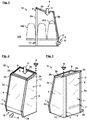
- Figures 2 and 3 Figure 12 show schematic perspective views of the separation area 1 from diagonally outside or diagonally inside.
- the inflatable separating area 10 can be used, for example, in a passenger cabin of an aircraft 100, as is exemplified in 7 you can see.
- the separation area 10 serves as an isolation cabin or isolation cell for the confinement of symptomatic cases, eg around a Isolate one person for the remainder of a flight to protect other passengers.
- the separating area 10 can be used if a passenger is suspected of having a highly contagious disease or if this has already been proven.
- Some common approaches to preventing the spread of pathogens include ensuring physical distancing between people, reducing contact opportunities, and enforcing personal protective equipment such as respirators.
- the IATA like other organizations, recommends keeping a distance of two meters between sick passengers and other passengers if they suspect an infectious disease during a flight. What these recommendations have in common is that a significant proportion of the seats can no longer be used.
- the separation area 10 is to provide a physical barrier for one or more potentially infectious persons, which can also be set up quickly and easily during the flight and does not entail any weight disadvantages.
- the separating area 10 is not limited to a fixed, predetermined position in the vehicle interior 101, but can in principle be set up at different locations. The separation area 10 can be used several times and should be disinfected if necessary.
- the separating area 10 separates two seats 102 of the last row of seats on the right aisle side in front of the sanitary facilities. On potentially infectious passenger 103 is seated in the window seat within the segregation area 10. 1 shows the situation in a sectional view from behind in relation to a longitudinal extension of the aircraft 100.
- the separation area 10 comprises a support structure 1 comprising a plurality of interconnected inflatable tubes 2a, 2b of flexible material arranged and adapted to form a self-supporting frame structure for the separation area 10 in an inflated condition.
- a support structure 1 comprising a plurality of interconnected inflatable tubes 2a, 2b of flexible material arranged and adapted to form a self-supporting frame structure for the separation area 10 in an inflated condition.
- Figures 1 to 3 As can be seen, in this embodiment three essentially vertically running hoses 2a are specifically provided, which stand on a floor of the aircraft 100 and thereby form a type of tripod. At an upper end they are held together by a ring or square of four transverse tubes 2b.
- the hoses 2a, 2b form a common volume which can be filled with air via a suitably attached valve using a hand pump, a small compressor and/or a compressed air source installed on board the aircraft 100.
- the separating device 10 also includes a pressure control device 13, which can be used to control and/or adjust the internal pressure of the hoses 2a, 2b.
- the pressure control device 13 can comprise a pressure sensor and a pressure display, for example.
- the valve mentioned above can be integrated into the pressure control device 13 .
- the hoses 2a, 2b stiffen as a result of the pressurization and thereby form a type of self-supporting framework or skeleton which defines an outer contour of the separating area 10 and gives it stability and stability.
- the internal pressure of the hoses 2a, 2b can already in the installation of Separating device 10 must be adjusted once such that the separating device 10 remains stable even in the event of pressure changes within the vehicle interior 101, e.g. even after the aircraft 100 has landed.
- the vertical hoses 2a are partially provided with kinks 12, while the transverse hoses 2b are slightly curved in order to follow an inner contour of the vehicle interior 101 as far as possible.
- the vertical tube 2a facing the aisle is straight, whereas the two opposite tubes 2a rest against an outer wall of the aircraft 101 and are kinked and accordingly run slightly obliquely along the outer wall.
- the tubes 2b running transversely are adapted to the lower contour of a stowage or luggage compartment (not shown) lying above them.
- the support structure 10 thus ends in principle at the top and bottom with a precise fit with the inner contour of the vehicle interior 101, with the vertical hoses 2a resting on the floor and the transverse hoses 2b resting on the ceiling or the storage compartment.
- the separating area 10 also includes a cover 3, which includes a plurality of flexible wall membranes 4, which connect the inflatable hoses 2a, 2b to one another over a surface area and are designed to separate the separating area 10 from the vehicle interior 101 in the inflated state.
- the wall membranes 4 can be made from a transparent or semi-transparent flame-retardant thermoplastic film.
- the hoses 2a, 2b of the support structure 1 can be made of the same material and welded to the wall membranes 4, for example. In total, a separate cell is thus formed, the supporting structure of which is formed by the hoses 2a, 2b and the outer walls of which are formed by the wall membranes 4.
- the separating area 10 is kept open at the top and bottom, with an air passage 9 located at the top allowing fresh air 11 to enter from the ventilation system of the aircraft 100 .
- an air passage 9 located at the top allowing fresh air 11 to enter from the ventilation system of the aircraft 100 .
- a slit-shaped air outlet 9 is provided near the floor, through which fresh air 11 can flow out of the separating area 10 again (in this area, the cover 3 therefore does not close flush with the floor).
- the air supply can be regulated in such a way that the flow conditions effectively set a slight negative pressure within the separating area 10, so that viruses or other pathogens, for example, do not escape from the separating area 10, even if it is not sealed off from the vehicle interior 101 in an airtight manner.
- a passenger 103 located in the separation area 10 still has access to a passenger service unit (PSU), emergency oxygen masks, etc. due to the upwardly open arrangement.
- PSU passenger service unit
- a reclosable passage opening 5 for entering and exiting the separation area 10 is also incorporated into one of the wall membranes 4, which can be opened and closed via a zipper 6.
- an emergency exit from the separation area 10 could also be implemented in this way, for example by using a safety zipper system such as the Quickburst system from the YKK Fastening Products Group or a corresponding system.
- the cover 3 can completely enclose the two seats 102, several passages 7 for elements of the adjoining third seat 102 are also formed in the aisle-side wall membrane 4, e.g. for passage of an armrest and/or a seat frame.
- the wall membrane 4 can be slotted from one or more sides towards the passages 7 (not shown), so that the wall membrane 4 can be guided around the corresponding elements and, if necessary, fastened around them in this arrangement (e.g. using Velcro fasteners, snap fasteners, etc.). Etc.).
- the separation area 10 is the Figures 1 to 3 carried only by three essentially vertically running hoses 2a.
- the separating area 10 can also include one or more fastening elements 8 .
- the transverse hoses 2b can be fixed to a ceiling, a stowage compartment and/or a wall of the vehicle interior 101 via such fastening elements 8 .
- a single fastening element 8 is shown as an example for this, which is designed as a suction cup and is attached to the supporting structure 1 of the separating area 10 in an area under which a fourth vertical support would have to be arranged from a symmetry point of view.
- the fastening element 8 thus compensates for the lack of a vertically running hose 2a on the right 2 or front center in 3 .
- Fixing using one or more suction cups offers the particular advantage that the separating area 10 can be retrofitted and installed in practically any cabin without the need for fastening means and/or special fastening points in the cabin.
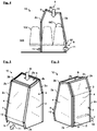
- Figures 1 to 3 demonstrate Figures 4 to 6 a variant of the invention, which has four essentially vertically running hoses 2a.
- the hoses 2a on the aisle side are also kinked, for example in order to meet a different cabin shape or different geometric requirements.
- the result is an extremely lightweight (e.g. a few kilograms) and yet particularly practical solution for an isolated area in a vehicle cabin, which can be folded up and stowed away in this form to save a great deal of space (e.g. in a carrying bag). All that is required for installation is a device for filling with air (e.g. an air pump) and, if necessary, one or more fastening elements such as suction cups or hooks.
- air e.g. an air pump
- fastening elements such as suction cups or hooks.
- the system also offers many advantages from a safety-critical point of view due to its low weight, flexibility, quick accessibility in the event of an emergency, etc.
- seats in the immediate vicinity of the separation area 10 can also be occupied without there being a relevant safety and/or infection risk for the passengers sitting there. This can generally improve seat occupancy.
Landscapes
- Engineering & Computer Science (AREA)
- Aviation & Aerospace Engineering (AREA)
- Transportation (AREA)
- Mechanical Engineering (AREA)
- Air Bags (AREA)
Priority Applications (3)
| Application Number | Priority Date | Filing Date | Title |
|---|---|---|---|
| EP21183563.2A EP4112468B1 (fr) | 2021-07-02 | 2021-07-02 | Zone de séparation gonflable pour un habitacle de véhicule |
| US17/854,497 US12240608B2 (en) | 2021-07-02 | 2022-06-30 | Inflatable separating region for a vehicle interior |
| CN202210766927.0A CN115556940A (zh) | 2021-07-02 | 2022-07-01 | 用于交通工具内部空间的可充气的分隔区域 |
Applications Claiming Priority (1)
| Application Number | Priority Date | Filing Date | Title |
|---|---|---|---|
| EP21183563.2A EP4112468B1 (fr) | 2021-07-02 | 2021-07-02 | Zone de séparation gonflable pour un habitacle de véhicule |
Publications (2)
| Publication Number | Publication Date |
|---|---|
| EP4112468A1 true EP4112468A1 (fr) | 2023-01-04 |
| EP4112468B1 EP4112468B1 (fr) | 2024-05-29 |
Family
ID=76764973
Family Applications (1)
| Application Number | Title | Priority Date | Filing Date |
|---|---|---|---|
| EP21183563.2A Active EP4112468B1 (fr) | 2021-07-02 | 2021-07-02 | Zone de séparation gonflable pour un habitacle de véhicule |
Country Status (3)
| Country | Link |
|---|---|
| US (1) | US12240608B2 (fr) |
| EP (1) | EP4112468B1 (fr) |
| CN (1) | CN115556940A (fr) |
Citations (6)
| Publication number | Priority date | Publication date | Assignee | Title |
|---|---|---|---|---|
| CN2547820Y (zh) * | 2002-04-19 | 2003-04-30 | 李良昭 | 气压支撑结构 |
| WO2008008910A2 (fr) * | 2006-07-12 | 2008-01-17 | Hkd International (Hk) Limited | Systèmes de support gonflable pour structures de récréation |
| EP2554477B1 (fr) | 2007-04-17 | 2014-04-30 | Lantal Textiles AG | Aéronef avec au moins une structure pour diviser un espace |
| CN102261128B (zh) * | 2011-05-10 | 2014-07-30 | 唐戍鸣 | 节点式气网架结构 |
| EP3272643A1 (fr) | 2016-07-20 | 2018-01-24 | Airbus Operations GmbH | Séparation de cabine pour un aéronef ou un engin spatial |
| US10888479B1 (en) | 2020-06-05 | 2021-01-12 | Alan Gershon | Biosafety enclosure for occupants of vehicles |
Family Cites Families (12)
| Publication number | Priority date | Publication date | Assignee | Title |
|---|---|---|---|---|
| US4440443A (en) * | 1981-04-10 | 1984-04-03 | Nordskog Robert A | Headrest |
| US4736762A (en) * | 1985-12-16 | 1988-04-12 | Wayman Joseph R | Anti-contamination means |
| DE29613200U1 (de) * | 1996-07-30 | 1996-10-10 | Liu, Chang-Hsiung, Yang-Mei, Taoyuan | Schutzvorrichtung mit aufblasbarer Rahmenstruktur |
| US20020083653A1 (en) * | 1999-09-10 | 2002-07-04 | Hilbert Clint J. | Rapidly deployable protective enclosure |
| US7578533B2 (en) * | 2006-09-15 | 2009-08-25 | The Boeing Company | Retractable and extendable enclosure member for a compartment of a transportation device |
| US8096082B2 (en) * | 2010-02-23 | 2012-01-17 | Gabriella Veronica Moran | Portable changing room that is inflatable |
| US8499371B1 (en) * | 2012-08-29 | 2013-08-06 | Mark A. Becker | Inflatable toilet shelter |
| FR3036097B1 (fr) * | 2015-05-12 | 2017-04-28 | Airbus Operations Sas | Dispositif d'acces a parois independantes mobiles permettant la communication securisee entre au moins deux zones d'une enceinte |
| FR3040022A1 (fr) * | 2015-08-14 | 2017-02-17 | Peugeot Citroen Automobiles Sa | Vehicule automobile comprenant une tente |
| US10155573B2 (en) * | 2016-03-02 | 2018-12-18 | New York University | Portable inflatable habitat with modular payload, system and method |
| AU2021246496A1 (en) * | 2020-04-03 | 2022-10-20 | The University Of Kansas | Negative pressure aerosolization mitigation devices and methods |
| KR102230159B1 (ko) * | 2020-12-08 | 2021-03-22 | 김영대 | 호흡기 바이러스 차단을 위한 좌석 착석 상태의 양압 방호 시스템 |
-
2021
- 2021-07-02 EP EP21183563.2A patent/EP4112468B1/fr active Active
-
2022
- 2022-06-30 US US17/854,497 patent/US12240608B2/en active Active
- 2022-07-01 CN CN202210766927.0A patent/CN115556940A/zh active Pending
Patent Citations (7)
| Publication number | Priority date | Publication date | Assignee | Title |
|---|---|---|---|---|
| CN2547820Y (zh) * | 2002-04-19 | 2003-04-30 | 李良昭 | 气压支撑结构 |
| WO2008008910A2 (fr) * | 2006-07-12 | 2008-01-17 | Hkd International (Hk) Limited | Systèmes de support gonflable pour structures de récréation |
| EP2554477B1 (fr) | 2007-04-17 | 2014-04-30 | Lantal Textiles AG | Aéronef avec au moins une structure pour diviser un espace |
| EP2139764B1 (fr) | 2007-04-17 | 2015-04-29 | Lantal Textiles AG | Structure comprenant une chambre à air |
| CN102261128B (zh) * | 2011-05-10 | 2014-07-30 | 唐戍鸣 | 节点式气网架结构 |
| EP3272643A1 (fr) | 2016-07-20 | 2018-01-24 | Airbus Operations GmbH | Séparation de cabine pour un aéronef ou un engin spatial |
| US10888479B1 (en) | 2020-06-05 | 2021-01-12 | Alan Gershon | Biosafety enclosure for occupants of vehicles |
Also Published As
| Publication number | Publication date |
|---|---|
| CN115556940A (zh) | 2023-01-03 |
| US12240608B2 (en) | 2025-03-04 |
| US20230002059A1 (en) | 2023-01-05 |
| EP4112468B1 (fr) | 2024-05-29 |
Similar Documents
| Publication | Publication Date | Title |
|---|---|---|
| DE60219367T2 (de) | Medizinische einheit für ein flugzeug | |
| EP2170702B1 (fr) | Module de repos ou de sieste destine a accueillir au moins un membre d'un personnel naviguant, equipe d'un module partiel pouvant etre amarre | |
| DE69806314T2 (de) | Ruhezone im oberen Bereich der Flugzeugkabine | |
| DE69827725T2 (de) | Rettungsvorrichtung für Ruhezone im oberen Bereich der Flugzeugkabine | |
| DE69829445T3 (de) | Schlafkabinen im Unterflurbereich eines Flugzeuges | |
| EP2423107B1 (fr) | Agencement de réception de passagers dans un moyen de transport | |
| DE102007019341B4 (de) | Flugzeug mit einem Aufenthalts- und Schlafmodul zur Unterbringung von zumindest einem Mitglied einer Flugzeugbesatzung | |
| DE102014205106A1 (de) | Schlafbox, Schlafboxenanordnung und Flugzeugbereich | |
| DE102007009544B4 (de) | Vorrichtung zum Transport und zur medizinischen Versorgung von Patienten sowie zur medizinischen Notfallversorgung in einem Flugzeug | |
| DE69816255T2 (de) | Flugzeugbettanordnung | |
| DE102011116519A1 (de) | Flugbegleitersitz, Anordnung mit einem Flugbegleitersitz und Flugzeugbereich | |
| DE102010054942A1 (de) | Raumoptimierter Flugbegleiter-Stehsitz für Luftfahrzeuge | |
| DE102007012376A1 (de) | Compartment zur Unterbringung von zumindest einem Mitglied einer Flugzeugbesatzung | |
| DE102014110820A1 (de) | Sitzanordnung in einer Kabine eines Flugzeugs und Flugzeug mit einer Kabine und einer darin integrierten Sitzanordnung | |
| DE102012023045A1 (de) | Flugbegleitersitzanordnung | |
| EP1602577A2 (fr) | Dispositf d'alimentation d'oxygène de secours | |
| DE3629505C2 (fr) | ||
| DE102018103099A1 (de) | Kabinenmodul mit Sanitäreinheit | |
| WO2009027229A1 (fr) | Cockpit protégé à zone de repos et installations sanitaires intégrées | |
| DE102010064100A1 (de) | Trennwand für eine Flugzeugkabine und Flugzeug | |
| DE102012005148A1 (de) | Passagierkabine für ein Fahrzeug und Fahrzeug mit einer Passagierkabine | |
| EP4112468B1 (fr) | Zone de séparation gonflable pour un habitacle de véhicule | |
| DE3829617C2 (fr) | ||
| DE102018104449B4 (de) | Mobile Sitzvorrichtung für ein Fortbewegungsmittel und Fortbewegungsmittel | |
| EP1934091B1 (fr) | Corridor verticalement amovible pour toilettes situees dans une zone de plafond |
Legal Events
| Date | Code | Title | Description |
|---|---|---|---|
| PUAI | Public reference made under article 153(3) epc to a published international application that has entered the european phase |
Free format text: ORIGINAL CODE: 0009012 |
|
| STAA | Information on the status of an ep patent application or granted ep patent |
Free format text: STATUS: THE APPLICATION HAS BEEN PUBLISHED |
|
| AK | Designated contracting states |
Kind code of ref document: A1 Designated state(s): AL AT BE BG CH CY CZ DE DK EE ES FI FR GB GR HR HU IE IS IT LI LT LU LV MC MK MT NL NO PL PT RO RS SE SI SK SM TR |
|
| STAA | Information on the status of an ep patent application or granted ep patent |
Free format text: STATUS: REQUEST FOR EXAMINATION WAS MADE |
|
| 17P | Request for examination filed |
Effective date: 20230315 |
|
| RBV | Designated contracting states (corrected) |
Designated state(s): AL AT BE BG CH CY CZ DE DK EE ES FI FR GB GR HR HU IE IS IT LI LT LU LV MC MK MT NL NO PL PT RO RS SE SI SK SM TR |
|
| GRAP | Despatch of communication of intention to grant a patent |
Free format text: ORIGINAL CODE: EPIDOSNIGR1 |
|
| STAA | Information on the status of an ep patent application or granted ep patent |
Free format text: STATUS: GRANT OF PATENT IS INTENDED |
|
| INTG | Intention to grant announced |
Effective date: 20240214 |
|
| GRAS | Grant fee paid |
Free format text: ORIGINAL CODE: EPIDOSNIGR3 |
|
| GRAA | (expected) grant |
Free format text: ORIGINAL CODE: 0009210 |
|
| STAA | Information on the status of an ep patent application or granted ep patent |
Free format text: STATUS: THE PATENT HAS BEEN GRANTED |
|
| AK | Designated contracting states |
Kind code of ref document: B1 Designated state(s): AL AT BE BG CH CY CZ DE DK EE ES FI FR GB GR HR HU IE IS IT LI LT LU LV MC MK MT NL NO PL PT RO RS SE SI SK SM TR |
|
| REG | Reference to a national code |
Ref country code: CH Ref legal event code: EP |
|
| REG | Reference to a national code |
Ref country code: IE Ref legal event code: FG4D Free format text: LANGUAGE OF EP DOCUMENT: GERMAN |
|
| REG | Reference to a national code |
Ref country code: DE Ref legal event code: R096 Ref document number: 502021003837 Country of ref document: DE |
|
| REG | Reference to a national code |
Ref country code: LT Ref legal event code: MG9D |
|
| REG | Reference to a national code |
Ref country code: NL Ref legal event code: MP Effective date: 20240529 |
|
| PG25 | Lapsed in a contracting state [announced via postgrant information from national office to epo] |
Ref country code: IS Free format text: LAPSE BECAUSE OF FAILURE TO SUBMIT A TRANSLATION OF THE DESCRIPTION OR TO PAY THE FEE WITHIN THE PRESCRIBED TIME-LIMIT Effective date: 20240929 |
|
| PG25 | Lapsed in a contracting state [announced via postgrant information from national office to epo] |
Ref country code: BG Free format text: LAPSE BECAUSE OF FAILURE TO SUBMIT A TRANSLATION OF THE DESCRIPTION OR TO PAY THE FEE WITHIN THE PRESCRIBED TIME-LIMIT Effective date: 20240529 |
|
| PG25 | Lapsed in a contracting state [announced via postgrant information from national office to epo] |
Ref country code: FI Free format text: LAPSE BECAUSE OF FAILURE TO SUBMIT A TRANSLATION OF THE DESCRIPTION OR TO PAY THE FEE WITHIN THE PRESCRIBED TIME-LIMIT Effective date: 20240529 Ref country code: HR Free format text: LAPSE BECAUSE OF FAILURE TO SUBMIT A TRANSLATION OF THE DESCRIPTION OR TO PAY THE FEE WITHIN THE PRESCRIBED TIME-LIMIT Effective date: 20240529 |
|
| PG25 | Lapsed in a contracting state [announced via postgrant information from national office to epo] |
Ref country code: GR Free format text: LAPSE BECAUSE OF FAILURE TO SUBMIT A TRANSLATION OF THE DESCRIPTION OR TO PAY THE FEE WITHIN THE PRESCRIBED TIME-LIMIT Effective date: 20240830 |
|
| PG25 | Lapsed in a contracting state [announced via postgrant information from national office to epo] |
Ref country code: ES Free format text: LAPSE BECAUSE OF FAILURE TO SUBMIT A TRANSLATION OF THE DESCRIPTION OR TO PAY THE FEE WITHIN THE PRESCRIBED TIME-LIMIT Effective date: 20240529 |
|
| PG25 | Lapsed in a contracting state [announced via postgrant information from national office to epo] |
Ref country code: PL Free format text: LAPSE BECAUSE OF FAILURE TO SUBMIT A TRANSLATION OF THE DESCRIPTION OR TO PAY THE FEE WITHIN THE PRESCRIBED TIME-LIMIT Effective date: 20240529 |
|
| PG25 | Lapsed in a contracting state [announced via postgrant information from national office to epo] |
Ref country code: LV Free format text: LAPSE BECAUSE OF FAILURE TO SUBMIT A TRANSLATION OF THE DESCRIPTION OR TO PAY THE FEE WITHIN THE PRESCRIBED TIME-LIMIT Effective date: 20240529 |
|
| PG25 | Lapsed in a contracting state [announced via postgrant information from national office to epo] |
Ref country code: PL Free format text: LAPSE BECAUSE OF FAILURE TO SUBMIT A TRANSLATION OF THE DESCRIPTION OR TO PAY THE FEE WITHIN THE PRESCRIBED TIME-LIMIT Effective date: 20240529 Ref country code: NO Free format text: LAPSE BECAUSE OF FAILURE TO SUBMIT A TRANSLATION OF THE DESCRIPTION OR TO PAY THE FEE WITHIN THE PRESCRIBED TIME-LIMIT Effective date: 20240829 Ref country code: LV Free format text: LAPSE BECAUSE OF FAILURE TO SUBMIT A TRANSLATION OF THE DESCRIPTION OR TO PAY THE FEE WITHIN THE PRESCRIBED TIME-LIMIT Effective date: 20240529 Ref country code: IS Free format text: LAPSE BECAUSE OF FAILURE TO SUBMIT A TRANSLATION OF THE DESCRIPTION OR TO PAY THE FEE WITHIN THE PRESCRIBED TIME-LIMIT Effective date: 20240929 Ref country code: HR Free format text: LAPSE BECAUSE OF FAILURE TO SUBMIT A TRANSLATION OF THE DESCRIPTION OR TO PAY THE FEE WITHIN THE PRESCRIBED TIME-LIMIT Effective date: 20240529 Ref country code: GR Free format text: LAPSE BECAUSE OF FAILURE TO SUBMIT A TRANSLATION OF THE DESCRIPTION OR TO PAY THE FEE WITHIN THE PRESCRIBED TIME-LIMIT Effective date: 20240830 Ref country code: FI Free format text: LAPSE BECAUSE OF FAILURE TO SUBMIT A TRANSLATION OF THE DESCRIPTION OR TO PAY THE FEE WITHIN THE PRESCRIBED TIME-LIMIT Effective date: 20240529 Ref country code: ES Free format text: LAPSE BECAUSE OF FAILURE TO SUBMIT A TRANSLATION OF THE DESCRIPTION OR TO PAY THE FEE WITHIN THE PRESCRIBED TIME-LIMIT Effective date: 20240529 Ref country code: BG Free format text: LAPSE BECAUSE OF FAILURE TO SUBMIT A TRANSLATION OF THE DESCRIPTION OR TO PAY THE FEE WITHIN THE PRESCRIBED TIME-LIMIT Effective date: 20240529 Ref country code: RS Free format text: LAPSE BECAUSE OF FAILURE TO SUBMIT A TRANSLATION OF THE DESCRIPTION OR TO PAY THE FEE WITHIN THE PRESCRIBED TIME-LIMIT Effective date: 20240829 |
|
| PG25 | Lapsed in a contracting state [announced via postgrant information from national office to epo] |
Ref country code: NL Free format text: LAPSE BECAUSE OF FAILURE TO SUBMIT A TRANSLATION OF THE DESCRIPTION OR TO PAY THE FEE WITHIN THE PRESCRIBED TIME-LIMIT Effective date: 20240529 |
|
| PG25 | Lapsed in a contracting state [announced via postgrant information from national office to epo] |
Ref country code: NL Free format text: LAPSE BECAUSE OF FAILURE TO SUBMIT A TRANSLATION OF THE DESCRIPTION OR TO PAY THE FEE WITHIN THE PRESCRIBED TIME-LIMIT Effective date: 20240529 |
|
| PG25 | Lapsed in a contracting state [announced via postgrant information from national office to epo] |
Ref country code: DK Free format text: LAPSE BECAUSE OF FAILURE TO SUBMIT A TRANSLATION OF THE DESCRIPTION OR TO PAY THE FEE WITHIN THE PRESCRIBED TIME-LIMIT Effective date: 20240529 |
|
| PG25 | Lapsed in a contracting state [announced via postgrant information from national office to epo] |
Ref country code: EE Free format text: LAPSE BECAUSE OF FAILURE TO SUBMIT A TRANSLATION OF THE DESCRIPTION OR TO PAY THE FEE WITHIN THE PRESCRIBED TIME-LIMIT Effective date: 20240529 |
|
| PG25 | Lapsed in a contracting state [announced via postgrant information from national office to epo] |
Ref country code: CZ Free format text: LAPSE BECAUSE OF FAILURE TO SUBMIT A TRANSLATION OF THE DESCRIPTION OR TO PAY THE FEE WITHIN THE PRESCRIBED TIME-LIMIT Effective date: 20240529 |
|
| PG25 | Lapsed in a contracting state [announced via postgrant information from national office to epo] |
Ref country code: SK Free format text: LAPSE BECAUSE OF FAILURE TO SUBMIT A TRANSLATION OF THE DESCRIPTION OR TO PAY THE FEE WITHIN THE PRESCRIBED TIME-LIMIT Effective date: 20240529 Ref country code: RO Free format text: LAPSE BECAUSE OF FAILURE TO SUBMIT A TRANSLATION OF THE DESCRIPTION OR TO PAY THE FEE WITHIN THE PRESCRIBED TIME-LIMIT Effective date: 20240529 |
|
| PG25 | Lapsed in a contracting state [announced via postgrant information from national office to epo] |
Ref country code: SM Free format text: LAPSE BECAUSE OF FAILURE TO SUBMIT A TRANSLATION OF THE DESCRIPTION OR TO PAY THE FEE WITHIN THE PRESCRIBED TIME-LIMIT Effective date: 20240529 |
|
| PG25 | Lapsed in a contracting state [announced via postgrant information from national office to epo] |
Ref country code: SM Free format text: LAPSE BECAUSE OF FAILURE TO SUBMIT A TRANSLATION OF THE DESCRIPTION OR TO PAY THE FEE WITHIN THE PRESCRIBED TIME-LIMIT Effective date: 20240529 Ref country code: SK Free format text: LAPSE BECAUSE OF FAILURE TO SUBMIT A TRANSLATION OF THE DESCRIPTION OR TO PAY THE FEE WITHIN THE PRESCRIBED TIME-LIMIT Effective date: 20240529 Ref country code: RO Free format text: LAPSE BECAUSE OF FAILURE TO SUBMIT A TRANSLATION OF THE DESCRIPTION OR TO PAY THE FEE WITHIN THE PRESCRIBED TIME-LIMIT Effective date: 20240529 Ref country code: EE Free format text: LAPSE BECAUSE OF FAILURE TO SUBMIT A TRANSLATION OF THE DESCRIPTION OR TO PAY THE FEE WITHIN THE PRESCRIBED TIME-LIMIT Effective date: 20240529 Ref country code: DK Free format text: LAPSE BECAUSE OF FAILURE TO SUBMIT A TRANSLATION OF THE DESCRIPTION OR TO PAY THE FEE WITHIN THE PRESCRIBED TIME-LIMIT Effective date: 20240529 Ref country code: CZ Free format text: LAPSE BECAUSE OF FAILURE TO SUBMIT A TRANSLATION OF THE DESCRIPTION OR TO PAY THE FEE WITHIN THE PRESCRIBED TIME-LIMIT Effective date: 20240529 |
|
| PG25 | Lapsed in a contracting state [announced via postgrant information from national office to epo] |
Ref country code: IT Free format text: LAPSE BECAUSE OF FAILURE TO SUBMIT A TRANSLATION OF THE DESCRIPTION OR TO PAY THE FEE WITHIN THE PRESCRIBED TIME-LIMIT Effective date: 20240529 Ref country code: MC Free format text: LAPSE BECAUSE OF FAILURE TO SUBMIT A TRANSLATION OF THE DESCRIPTION OR TO PAY THE FEE WITHIN THE PRESCRIBED TIME-LIMIT Effective date: 20240529 |
|
| REG | Reference to a national code |
Ref country code: CH Ref legal event code: PL |
|
| REG | Reference to a national code |
Ref country code: DE Ref legal event code: R097 Ref document number: 502021003837 Country of ref document: DE |
|
| PG25 | Lapsed in a contracting state [announced via postgrant information from national office to epo] |
Ref country code: LU Free format text: LAPSE BECAUSE OF NON-PAYMENT OF DUE FEES Effective date: 20240702 |
|
| PG25 | Lapsed in a contracting state [announced via postgrant information from national office to epo] |
Ref country code: LU Free format text: LAPSE BECAUSE OF NON-PAYMENT OF DUE FEES Effective date: 20240702 |
|
| PLBE | No opposition filed within time limit |
Free format text: ORIGINAL CODE: 0009261 |
|
| STAA | Information on the status of an ep patent application or granted ep patent |
Free format text: STATUS: NO OPPOSITION FILED WITHIN TIME LIMIT |
|
| PG25 | Lapsed in a contracting state [announced via postgrant information from national office to epo] |
Ref country code: BE Free format text: LAPSE BECAUSE OF NON-PAYMENT OF DUE FEES Effective date: 20240731 Ref country code: CH Free format text: LAPSE BECAUSE OF NON-PAYMENT OF DUE FEES Effective date: 20240731 Ref country code: SI Free format text: LAPSE BECAUSE OF FAILURE TO SUBMIT A TRANSLATION OF THE DESCRIPTION OR TO PAY THE FEE WITHIN THE PRESCRIBED TIME-LIMIT Effective date: 20240529 |
|
| 26N | No opposition filed |
Effective date: 20250303 |
|
| REG | Reference to a national code |
Ref country code: BE Ref legal event code: MM Effective date: 20240731 |
|
| PG25 | Lapsed in a contracting state [announced via postgrant information from national office to epo] |
Ref country code: IE Free format text: LAPSE BECAUSE OF NON-PAYMENT OF DUE FEES Effective date: 20240702 |
|
| PG25 | Lapsed in a contracting state [announced via postgrant information from national office to epo] |
Ref country code: SE Free format text: LAPSE BECAUSE OF FAILURE TO SUBMIT A TRANSLATION OF THE DESCRIPTION OR TO PAY THE FEE WITHIN THE PRESCRIBED TIME-LIMIT Effective date: 20240529 |
|
| PGFP | Annual fee paid to national office [announced via postgrant information from national office to epo] |
Ref country code: DE Payment date: 20250722 Year of fee payment: 5 |
|
| PGFP | Annual fee paid to national office [announced via postgrant information from national office to epo] |
Ref country code: GB Payment date: 20250724 Year of fee payment: 5 |
|
| PGFP | Annual fee paid to national office [announced via postgrant information from national office to epo] |
Ref country code: AT Payment date: 20251020 Year of fee payment: 5 Ref country code: FR Payment date: 20250725 Year of fee payment: 5 |
|
| PG25 | Lapsed in a contracting state [announced via postgrant information from national office to epo] |
Ref country code: CY Free format text: LAPSE BECAUSE OF FAILURE TO SUBMIT A TRANSLATION OF THE DESCRIPTION OR TO PAY THE FEE WITHIN THE PRESCRIBED TIME-LIMIT; INVALID AB INITIO Effective date: 20210702 |
|
| PG25 | Lapsed in a contracting state [announced via postgrant information from national office to epo] |
Ref country code: HU Free format text: LAPSE BECAUSE OF FAILURE TO SUBMIT A TRANSLATION OF THE DESCRIPTION OR TO PAY THE FEE WITHIN THE PRESCRIBED TIME-LIMIT; INVALID AB INITIO Effective date: 20210702 |