EP4112823A1 - Engin de chantier - Google Patents
Engin de chantier Download PDFInfo
- Publication number
- EP4112823A1 EP4112823A1 EP21761794.3A EP21761794A EP4112823A1 EP 4112823 A1 EP4112823 A1 EP 4112823A1 EP 21761794 A EP21761794 A EP 21761794A EP 4112823 A1 EP4112823 A1 EP 4112823A1
- Authority
- EP
- European Patent Office
- Prior art keywords
- working fluid
- main pump
- boom
- cylinder
- bucket
- Prior art date
- Legal status (The legal status is an assumption and is not a legal conclusion. Google has not performed a legal analysis and makes no representation as to the accuracy of the status listed.)
- Pending
Links
Images







Classifications
-
- E—FIXED CONSTRUCTIONS
- E02—HYDRAULIC ENGINEERING; FOUNDATIONS; SOIL SHIFTING
- E02F—DREDGING; SOIL-SHIFTING
- E02F9/00—Component parts of dredgers or soil-shifting machines, not restricted to one of the kinds covered by groups E02F3/00 - E02F7/00
- E02F9/20—Drives; Control devices
- E02F9/22—Hydraulic or pneumatic drives
- E02F9/2278—Hydraulic circuits
- E02F9/2282—Systems using center bypass type changeover valves
-
- E—FIXED CONSTRUCTIONS
- E02—HYDRAULIC ENGINEERING; FOUNDATIONS; SOIL SHIFTING
- E02F—DREDGING; SOIL-SHIFTING
- E02F9/00—Component parts of dredgers or soil-shifting machines, not restricted to one of the kinds covered by groups E02F3/00 - E02F7/00
- E02F9/20—Drives; Control devices
- E02F9/22—Hydraulic or pneumatic drives
- E02F9/2221—Control of flow rate; Load sensing arrangements
-
- E—FIXED CONSTRUCTIONS
- E02—HYDRAULIC ENGINEERING; FOUNDATIONS; SOIL SHIFTING
- E02F—DREDGING; SOIL-SHIFTING
- E02F9/00—Component parts of dredgers or soil-shifting machines, not restricted to one of the kinds covered by groups E02F3/00 - E02F7/00
- E02F9/20—Drives; Control devices
- E02F9/22—Hydraulic or pneumatic drives
- E02F9/2278—Hydraulic circuits
- E02F9/2292—Systems with two or more pumps
-
- E—FIXED CONSTRUCTIONS
- E02—HYDRAULIC ENGINEERING; FOUNDATIONS; SOIL SHIFTING
- E02F—DREDGING; SOIL-SHIFTING
- E02F9/00—Component parts of dredgers or soil-shifting machines, not restricted to one of the kinds covered by groups E02F3/00 - E02F7/00
- E02F9/20—Drives; Control devices
- E02F9/2058—Electric or electro-mechanical or mechanical control devices of vehicle sub-units
- E02F9/2062—Control of propulsion units
-
- E—FIXED CONSTRUCTIONS
- E02—HYDRAULIC ENGINEERING; FOUNDATIONS; SOIL SHIFTING
- E02F—DREDGING; SOIL-SHIFTING
- E02F9/00—Component parts of dredgers or soil-shifting machines, not restricted to one of the kinds covered by groups E02F3/00 - E02F7/00
- E02F9/20—Drives; Control devices
- E02F9/22—Hydraulic or pneumatic drives
- E02F9/2217—Hydraulic or pneumatic drives with energy recovery arrangements, e.g. using accumulators, flywheels
-
- E—FIXED CONSTRUCTIONS
- E02—HYDRAULIC ENGINEERING; FOUNDATIONS; SOIL SHIFTING
- E02F—DREDGING; SOIL-SHIFTING
- E02F9/00—Component parts of dredgers or soil-shifting machines, not restricted to one of the kinds covered by groups E02F3/00 - E02F7/00
- E02F9/20—Drives; Control devices
- E02F9/22—Hydraulic or pneumatic drives
- E02F9/2221—Control of flow rate; Load sensing arrangements
- E02F9/2225—Control of flow rate; Load sensing arrangements using pressure-compensating valves
- E02F9/2228—Control of flow rate; Load sensing arrangements using pressure-compensating valves including an electronic controller
-
- E—FIXED CONSTRUCTIONS
- E02—HYDRAULIC ENGINEERING; FOUNDATIONS; SOIL SHIFTING
- E02F—DREDGING; SOIL-SHIFTING
- E02F9/00—Component parts of dredgers or soil-shifting machines, not restricted to one of the kinds covered by groups E02F3/00 - E02F7/00
- E02F9/20—Drives; Control devices
- E02F9/22—Hydraulic or pneumatic drives
- E02F9/2221—Control of flow rate; Load sensing arrangements
- E02F9/2232—Control of flow rate; Load sensing arrangements using one or more variable displacement pumps
- E02F9/2235—Control of flow rate; Load sensing arrangements using one or more variable displacement pumps including an electronic controller
-
- E—FIXED CONSTRUCTIONS
- E02—HYDRAULIC ENGINEERING; FOUNDATIONS; SOIL SHIFTING
- E02F—DREDGING; SOIL-SHIFTING
- E02F9/00—Component parts of dredgers or soil-shifting machines, not restricted to one of the kinds covered by groups E02F3/00 - E02F7/00
- E02F9/20—Drives; Control devices
- E02F9/22—Hydraulic or pneumatic drives
- E02F9/2221—Control of flow rate; Load sensing arrangements
- E02F9/2239—Control of flow rate; Load sensing arrangements using two or more pumps with cross-assistance
- E02F9/2242—Control of flow rate; Load sensing arrangements using two or more pumps with cross-assistance including an electronic controller
-
- E—FIXED CONSTRUCTIONS
- E02—HYDRAULIC ENGINEERING; FOUNDATIONS; SOIL SHIFTING
- E02F—DREDGING; SOIL-SHIFTING
- E02F9/00—Component parts of dredgers or soil-shifting machines, not restricted to one of the kinds covered by groups E02F3/00 - E02F7/00
- E02F9/20—Drives; Control devices
- E02F9/22—Hydraulic or pneumatic drives
- E02F9/2264—Arrangements or adaptations of elements for hydraulic drives
- E02F9/2267—Valves or distributors
-
- E—FIXED CONSTRUCTIONS
- E02—HYDRAULIC ENGINEERING; FOUNDATIONS; SOIL SHIFTING
- E02F—DREDGING; SOIL-SHIFTING
- E02F9/00—Component parts of dredgers or soil-shifting machines, not restricted to one of the kinds covered by groups E02F3/00 - E02F7/00
- E02F9/20—Drives; Control devices
- E02F9/22—Hydraulic or pneumatic drives
- E02F9/2264—Arrangements or adaptations of elements for hydraulic drives
- E02F9/2275—Hoses and supports therefor and protection therefor
-
- E—FIXED CONSTRUCTIONS
- E02—HYDRAULIC ENGINEERING; FOUNDATIONS; SOIL SHIFTING
- E02F—DREDGING; SOIL-SHIFTING
- E02F9/00—Component parts of dredgers or soil-shifting machines, not restricted to one of the kinds covered by groups E02F3/00 - E02F7/00
- E02F9/20—Drives; Control devices
- E02F9/22—Hydraulic or pneumatic drives
- E02F9/2278—Hydraulic circuits
- E02F9/2289—Closed circuit
-
- E—FIXED CONSTRUCTIONS
- E02—HYDRAULIC ENGINEERING; FOUNDATIONS; SOIL SHIFTING
- E02F—DREDGING; SOIL-SHIFTING
- E02F9/00—Component parts of dredgers or soil-shifting machines, not restricted to one of the kinds covered by groups E02F3/00 - E02F7/00
- E02F9/20—Drives; Control devices
- E02F9/22—Hydraulic or pneumatic drives
- E02F9/2278—Hydraulic circuits
- E02F9/2296—Systems with a variable displacement pump
-
- F—MECHANICAL ENGINEERING; LIGHTING; HEATING; WEAPONS; BLASTING
- F15—FLUID-PRESSURE ACTUATORS; HYDRAULICS OR PNEUMATICS IN GENERAL
- F15B—SYSTEMS ACTING BY MEANS OF FLUIDS IN GENERAL; FLUID-PRESSURE ACTUATORS, e.g. SERVOMOTORS; DETAILS OF FLUID-PRESSURE SYSTEMS, NOT OTHERWISE PROVIDED FOR
- F15B1/00—Installations or systems with accumulators; Supply reservoir or sump assemblies
- F15B1/02—Installations or systems with accumulators
- F15B1/024—Installations or systems with accumulators used as a supplementary power source, e.g. to store energy in idle periods to balance pump load
-
- F—MECHANICAL ENGINEERING; LIGHTING; HEATING; WEAPONS; BLASTING
- F15—FLUID-PRESSURE ACTUATORS; HYDRAULICS OR PNEUMATICS IN GENERAL
- F15B—SYSTEMS ACTING BY MEANS OF FLUIDS IN GENERAL; FLUID-PRESSURE ACTUATORS, e.g. SERVOMOTORS; DETAILS OF FLUID-PRESSURE SYSTEMS, NOT OTHERWISE PROVIDED FOR
- F15B11/00—Servomotor systems without provision for follow-up action; Circuits therefor
- F15B11/16—Servomotor systems without provision for follow-up action; Circuits therefor with two or more servomotors
- F15B11/17—Servomotor systems without provision for follow-up action; Circuits therefor with two or more servomotors using two or more pumps
-
- F—MECHANICAL ENGINEERING; LIGHTING; HEATING; WEAPONS; BLASTING
- F15—FLUID-PRESSURE ACTUATORS; HYDRAULICS OR PNEUMATICS IN GENERAL
- F15B—SYSTEMS ACTING BY MEANS OF FLUIDS IN GENERAL; FLUID-PRESSURE ACTUATORS, e.g. SERVOMOTORS; DETAILS OF FLUID-PRESSURE SYSTEMS, NOT OTHERWISE PROVIDED FOR
- F15B21/00—Common features of fluid actuator systems; Fluid-pressure actuator systems or details thereof, not covered by any other group of this subclass
- F15B21/14—Energy-recuperation means
-
- F—MECHANICAL ENGINEERING; LIGHTING; HEATING; WEAPONS; BLASTING
- F15—FLUID-PRESSURE ACTUATORS; HYDRAULICS OR PNEUMATICS IN GENERAL
- F15B—SYSTEMS ACTING BY MEANS OF FLUIDS IN GENERAL; FLUID-PRESSURE ACTUATORS, e.g. SERVOMOTORS; DETAILS OF FLUID-PRESSURE SYSTEMS, NOT OTHERWISE PROVIDED FOR
- F15B2211/00—Circuits for servomotor systems
- F15B2211/20—Fluid pressure source, e.g. accumulator or variable axial piston pump
- F15B2211/205—Systems with pumps
- F15B2211/20507—Type of prime mover
- F15B2211/20523—Internal combustion engine
-
- F—MECHANICAL ENGINEERING; LIGHTING; HEATING; WEAPONS; BLASTING
- F15—FLUID-PRESSURE ACTUATORS; HYDRAULICS OR PNEUMATICS IN GENERAL
- F15B—SYSTEMS ACTING BY MEANS OF FLUIDS IN GENERAL; FLUID-PRESSURE ACTUATORS, e.g. SERVOMOTORS; DETAILS OF FLUID-PRESSURE SYSTEMS, NOT OTHERWISE PROVIDED FOR
- F15B2211/00—Circuits for servomotor systems
- F15B2211/20—Fluid pressure source, e.g. accumulator or variable axial piston pump
- F15B2211/205—Systems with pumps
- F15B2211/2053—Type of pump
- F15B2211/20546—Type of pump variable capacity
-
- F—MECHANICAL ENGINEERING; LIGHTING; HEATING; WEAPONS; BLASTING
- F15—FLUID-PRESSURE ACTUATORS; HYDRAULICS OR PNEUMATICS IN GENERAL
- F15B—SYSTEMS ACTING BY MEANS OF FLUIDS IN GENERAL; FLUID-PRESSURE ACTUATORS, e.g. SERVOMOTORS; DETAILS OF FLUID-PRESSURE SYSTEMS, NOT OTHERWISE PROVIDED FOR
- F15B2211/00—Circuits for servomotor systems
- F15B2211/20—Fluid pressure source, e.g. accumulator or variable axial piston pump
- F15B2211/205—Systems with pumps
- F15B2211/2053—Type of pump
- F15B2211/20561—Type of pump reversible
-
- F—MECHANICAL ENGINEERING; LIGHTING; HEATING; WEAPONS; BLASTING
- F15—FLUID-PRESSURE ACTUATORS; HYDRAULICS OR PNEUMATICS IN GENERAL
- F15B—SYSTEMS ACTING BY MEANS OF FLUIDS IN GENERAL; FLUID-PRESSURE ACTUATORS, e.g. SERVOMOTORS; DETAILS OF FLUID-PRESSURE SYSTEMS, NOT OTHERWISE PROVIDED FOR
- F15B2211/00—Circuits for servomotor systems
- F15B2211/20—Fluid pressure source, e.g. accumulator or variable axial piston pump
- F15B2211/205—Systems with pumps
- F15B2211/2053—Type of pump
- F15B2211/20569—Type of pump capable of working as pump and motor
-
- F—MECHANICAL ENGINEERING; LIGHTING; HEATING; WEAPONS; BLASTING
- F15—FLUID-PRESSURE ACTUATORS; HYDRAULICS OR PNEUMATICS IN GENERAL
- F15B—SYSTEMS ACTING BY MEANS OF FLUIDS IN GENERAL; FLUID-PRESSURE ACTUATORS, e.g. SERVOMOTORS; DETAILS OF FLUID-PRESSURE SYSTEMS, NOT OTHERWISE PROVIDED FOR
- F15B2211/00—Circuits for servomotor systems
- F15B2211/20—Fluid pressure source, e.g. accumulator or variable axial piston pump
- F15B2211/205—Systems with pumps
- F15B2211/20576—Systems with pumps with multiple pumps
-
- F—MECHANICAL ENGINEERING; LIGHTING; HEATING; WEAPONS; BLASTING
- F15—FLUID-PRESSURE ACTUATORS; HYDRAULICS OR PNEUMATICS IN GENERAL
- F15B—SYSTEMS ACTING BY MEANS OF FLUIDS IN GENERAL; FLUID-PRESSURE ACTUATORS, e.g. SERVOMOTORS; DETAILS OF FLUID-PRESSURE SYSTEMS, NOT OTHERWISE PROVIDED FOR
- F15B2211/00—Circuits for servomotor systems
- F15B2211/20—Fluid pressure source, e.g. accumulator or variable axial piston pump
- F15B2211/21—Systems with pressure sources other than pumps, e.g. with a pyrotechnical charge
- F15B2211/212—Systems with pressure sources other than pumps, e.g. with a pyrotechnical charge the pressure sources being accumulators
-
- F—MECHANICAL ENGINEERING; LIGHTING; HEATING; WEAPONS; BLASTING
- F15—FLUID-PRESSURE ACTUATORS; HYDRAULICS OR PNEUMATICS IN GENERAL
- F15B—SYSTEMS ACTING BY MEANS OF FLUIDS IN GENERAL; FLUID-PRESSURE ACTUATORS, e.g. SERVOMOTORS; DETAILS OF FLUID-PRESSURE SYSTEMS, NOT OTHERWISE PROVIDED FOR
- F15B2211/00—Circuits for servomotor systems
- F15B2211/30—Directional control
- F15B2211/305—Directional control characterised by the type of valves
- F15B2211/3056—Assemblies of multiple valves
- F15B2211/3059—Assemblies of multiple valves having multiple valves for multiple output members
-
- F—MECHANICAL ENGINEERING; LIGHTING; HEATING; WEAPONS; BLASTING
- F15—FLUID-PRESSURE ACTUATORS; HYDRAULICS OR PNEUMATICS IN GENERAL
- F15B—SYSTEMS ACTING BY MEANS OF FLUIDS IN GENERAL; FLUID-PRESSURE ACTUATORS, e.g. SERVOMOTORS; DETAILS OF FLUID-PRESSURE SYSTEMS, NOT OTHERWISE PROVIDED FOR
- F15B2211/00—Circuits for servomotor systems
- F15B2211/30—Directional control
- F15B2211/315—Directional control characterised by the connections of the valve or valves in the circuit
- F15B2211/31523—Directional control characterised by the connections of the valve or valves in the circuit being connected to a pressure source and an output member
- F15B2211/31529—Directional control characterised by the connections of the valve or valves in the circuit being connected to a pressure source and an output member having a single pressure source and a single output member
-
- F—MECHANICAL ENGINEERING; LIGHTING; HEATING; WEAPONS; BLASTING
- F15—FLUID-PRESSURE ACTUATORS; HYDRAULICS OR PNEUMATICS IN GENERAL
- F15B—SYSTEMS ACTING BY MEANS OF FLUIDS IN GENERAL; FLUID-PRESSURE ACTUATORS, e.g. SERVOMOTORS; DETAILS OF FLUID-PRESSURE SYSTEMS, NOT OTHERWISE PROVIDED FOR
- F15B2211/00—Circuits for servomotor systems
- F15B2211/30—Directional control
- F15B2211/315—Directional control characterised by the connections of the valve or valves in the circuit
- F15B2211/31523—Directional control characterised by the connections of the valve or valves in the circuit being connected to a pressure source and an output member
- F15B2211/31535—Directional control characterised by the connections of the valve or valves in the circuit being connected to a pressure source and an output member having multiple pressure sources and a single output member
-
- F—MECHANICAL ENGINEERING; LIGHTING; HEATING; WEAPONS; BLASTING
- F15—FLUID-PRESSURE ACTUATORS; HYDRAULICS OR PNEUMATICS IN GENERAL
- F15B—SYSTEMS ACTING BY MEANS OF FLUIDS IN GENERAL; FLUID-PRESSURE ACTUATORS, e.g. SERVOMOTORS; DETAILS OF FLUID-PRESSURE SYSTEMS, NOT OTHERWISE PROVIDED FOR
- F15B2211/00—Circuits for servomotor systems
- F15B2211/70—Output members, e.g. hydraulic motors or cylinders or control therefor
- F15B2211/71—Multiple output members, e.g. multiple hydraulic motors or cylinders
- F15B2211/7135—Combinations of output members of different types, e.g. single-acting cylinders with rotary motors
-
- F—MECHANICAL ENGINEERING; LIGHTING; HEATING; WEAPONS; BLASTING
- F15—FLUID-PRESSURE ACTUATORS; HYDRAULICS OR PNEUMATICS IN GENERAL
- F15B—SYSTEMS ACTING BY MEANS OF FLUIDS IN GENERAL; FLUID-PRESSURE ACTUATORS, e.g. SERVOMOTORS; DETAILS OF FLUID-PRESSURE SYSTEMS, NOT OTHERWISE PROVIDED FOR
- F15B2211/00—Circuits for servomotor systems
- F15B2211/70—Output members, e.g. hydraulic motors or cylinders or control therefor
- F15B2211/71—Multiple output members, e.g. multiple hydraulic motors or cylinders
- F15B2211/7142—Multiple output members, e.g. multiple hydraulic motors or cylinders the output members being arranged in multiple groups
-
- F—MECHANICAL ENGINEERING; LIGHTING; HEATING; WEAPONS; BLASTING
- F15—FLUID-PRESSURE ACTUATORS; HYDRAULICS OR PNEUMATICS IN GENERAL
- F15B—SYSTEMS ACTING BY MEANS OF FLUIDS IN GENERAL; FLUID-PRESSURE ACTUATORS, e.g. SERVOMOTORS; DETAILS OF FLUID-PRESSURE SYSTEMS, NOT OTHERWISE PROVIDED FOR
- F15B2211/00—Circuits for servomotor systems
- F15B2211/80—Other types of control related to particular problems or conditions
- F15B2211/88—Control measures for saving energy
Definitions
- the disclosure relates to a construction machine and, more particularly, to a construction machine that uses a plurality of hydraulic pumps to drive various driving devices.
- a construction machine generally refers to all machines used in public works, construction works, or industrial sites.
- the construction machine has an engine and a hydraulic pump that is operated by power of the engine, runs with power generated through the engine and the hydraulic pump, or drives various working devices.
- an excavator which is a type of construction machine, performs work such as excavation work to dig into the ground in a civil engineering site, building, or construction site, loading work to transport soil, cracking work to demolish buildings, and grading work to clear the ground.
- the construction machine performs operations such as an excavation operation, a boom-up swing operation, a dump operation, and a work running operation.
- the excavator that is the construction machine includes a lower running body for movement, an upper rotary body mounted on the lower running body to be rotated, and various working devices and a driver's seat installed on the upper rotary body.
- two main pumps 31 and 32 supply working fluid.
- the working fluid supplied by the two main pumps 31 and 32 is distributed from a main control valve (MCV) 50 to each driving device.
- MCV main control valve
- the driving device is set to supply working fluid to each main pump 31 or 32.
- the driving device includes a boom cylinder 71 for driving a boom, an arm cylinder 72 for driving an arm, a bucket cylinder 73 for driving a bucket, a rotation motor 75 for rotating the upper rotary body, and a first running motor 76 and a second running motor 77 for running.
- the main control valve 50 includes a first boom valve 51a for supplying working fluid discharged by the first main pump 31 to the boom cylinder 71, a first running valve 56 for supplying working fluid discharged by the first main pump 31 to the first running motor 76, a bucket valve 53 for supplying working fluid discharged by the first main pump 31 to the bucket cylinder 73, a rotation valve 55 for supplying working fluid discharged by the second main pump 32 to the rotation motor 75, a second running valve 57 for supplying working fluid discharged by the second main pump 32 to the second running motor 77, a first arm valve 52a for supplying working fluid discharged by the second main pump 32 to the arm cylinder 75, an option valve 59 for driving a device that is optionally mounted on the construction machine 10, a straight running valve 58 for supplying working fluid discharged by the first main pump 31 during straight running to the first running motor 76 as well as the second running motor 77, a second arm valve 52b for joining working fluid discharged by the first main pump 31 to the arm cylinder 72, and
- the boom cylinder 71 and the arm cylinder 72 require a relatively larger flow rate of working fluid compared to other driving devices depending on a load.
- the first boom valve 51a of the main control valve 50 mainly supplies working fluid discharged by the first main pump 31 to the boom cylinder 71
- the second boom valve 51b may complementarily supply working fluid discharged by the second main pump 32 to the boom cylinder 71.
- the first arm valve 52a of the main control valve 50 mainly supplies working fluid discharged by the second main pump 32 to the arm cylinder 72
- the second arm valve 52b may complementarily supply working fluid discharged by the first main pump 31 to the arm cylinder 72.
- either of the main pumps 31 and 32 may often supply working fluid to a plurality of driving devices. Further, the pressure of working fluid required for driving the driving device may be different for each driving device.
- the main pumps 31 and 32 supplies working fluid to the plurality of driving devices, a lot of energy loss occurs in the driving device operating at a relatively low pressure. This is because the main pumps 31 and 32 are controlled to discharge working fluid depending on the driving device operating at the highest pressure among the plurality of driving devices that are supplied with working fluid. Therefore, working fluid with an excessively high pressure is supplied to the driving device driven at a relatively lower pressure.
- the first main pump 31 supplying the working fluid to the bucket cylinder 73 discharges the working fluid of a relatively low pressure depending on the working pressure of the bucket cylinder 73
- the second main pump 32 supplying the working fluid to the arm cylinder 72 discharges the working fluid of a relatively high pressure depending on the working pressure of the arm cylinder 72.
- the second arm valve 52b supplies working fluid, discharged from the first main pump 31, to the arm cylinder 72 so as to replenish the working fluid supplied to the arm cylinder 72
- the pressure of the working fluid discharged from the first main pump 31 rises to the working pressure of the arm cylinder 72.
- An embodiment of the present disclosure provides a construction machine capable of minimizing an energy loss when a plurality of driving devices are simultaneously operated.
- a construction machine construction includes a boom cylinder driving a boom, a rotation motor rotating a rotary body, an arm cylinder driving an arm, a bucket cylinder driving a bucket, a first main pump supplying working fluid to the boom cylinder or recovering working fluid discharged from the boom cylinder, a second main pump supplying working fluid to the rotation motor or recovering working fluid discharged from the rotation motor, and a third main pump supplying working fluid to the arm cylinder or the bucket cylinder.
- the construction machine may further include an engine connected to the first main pump, a first boom hydraulic line connecting a head side of the boom cylinder and the first main pump, and a second boom hydraulic line connecting a rod side of the boom cylinder and the first main pump.
- the first main pump may be operated with the working fluid discharged from the boom cylinder when the boom is moved down, thus supplying energy to the engine.
- the construction machine may further include an accumulator for accumulating the working fluid, a boom regenerative valve connected to the first boom hydraulic line and the second boom hydraulic line, and a boom regenerative line connecting the boom regenerative valve and the accumulator.
- the first main pump may be operated with the working fluid supplied by the accumulator, thus supplying energy to the engine.
- the construction machine may further include a first rotation hydraulic line connecting one side of the rotation motor and the second main pump, and a second rotation hydraulic line connecting the other side of the rotation motor and the second main pump.
- the engine may be connected to the second main pump, and the second main pump may be operated with the working fluid discharged from the rotation motor when the rotation motor is decelerated, thus supplying energy to the engine.
- the construction machine may further include an accumulator for accumulating the working fluid, a rotation regenerative valve connected to the first rotation hydraulic line and the second rotation hydraulic line, and a rotation regenerative line connecting the rotation regenerative valve and the accumulator.
- the second main pump may be operated with the working fluid supplied by the accumulator, thus supplying energy to the engine.
- the first main pump may be a bidirectional pump that selectively discharges the working fluid to either of the first boom hydraulic line or the second boom hydraulic line
- the second main pump may be a bidirectional pump that selectively discharges the working fluid to either of the first rotation hydraulic line or the second rotation hydraulic line.
- the construction machine may further include a drain tank storing the working fluid discharged from the arm cylinder and the bucket cylinder, and a drain line connecting the arm cylinder, the bucket cylinder, and the drain tank.
- the construction machine may further include an engine connected to the first main pump, the second main pump, and the third main pump to provide power. Further, at least one of the first main pump and the second main pump may additionally supply energy to the engine during a regenerative operation.
- the working fluid discharged from the first main pump may be supplied to the boom cylinder
- the working fluid discharged from the second main pump may be supplied to the bucket cylinder instead of the rotation motor
- the working fluid discharged from the third main pump may be supplied to the arm cylinder.
- the construction machine may further include a rotation valve controlling the working fluid supplied to the rotation motor, and a bucket hydraulic line for supplying the working fluid to the bucket cylinder. Further, the rotation valve may block the working fluid supplied by the second main pump to the rotation motor, and the working fluid discharged from the second main pump may be supplied through the bucket hydraulic line to the bucket cylinder.
- the working fluid discharged from the first main pump may be supplied to the boom cylinder
- the working fluid discharged from the second main pump may be supplied to the rotation motor
- the working fluid discharged from the third main pump may be supplied to the bucket cylinder instead of the arm cylinder.
- the construction machine may further include an arm valve controlling the working fluid supplied to the arm cylinder, and an arm bucket joining line connected to the bucket cylinder. Further, the arm valve may block the working fluid supplied by the third main pump to the arm cylinder, and the working fluid discharged from the third main pump may be supplied through the arm bucket joining line to the bucket cylinder.
- the working fluid discharged from the first main pump may be supplied to the boom cylinder
- the working fluid discharged from the second main pump may be supplied to the rotation motor
- the working fluid discharged from the third main pump may be supplied to the bucket cylinder along with the arm cylinder.
- the construction machine may further include an arm valve controlling the working fluid supplied to the arm cylinder, and a bucket valve controlling the working fluid supplied to the bucket cylinder. Further, the arm valve and the bucket valve may supply the working fluid discharged from the third main pump to the arm cylinder and the bucket cylinder, respectively.
- a construction machine can minimize an energy loss when a plurality of driving devices are simultaneously operated.
- a construction machine can improve energy utilization efficiency by recovering energy wasted from a driving device.
- an embodiment of the present disclosure will be described in detail in an idealized form. As a result, various changes of the drawings are expected. Thus, an embodiment is not limited to a specific shape of an illustrated area, and includes a change in shape by manufacturing, for example.
- the construction machine 101 may include a lower running body for movement, an upper rotary body mounted on the lower running body to be rotated, and a boom, an arm, and a bucket installed on the upper rotary body.
- the construction machine 101 includes a boom cylinder 710, a rotation motor 750, an arm cylinder 720, a bucket cylinder 730, a first main pump 310, a second main pump 320, and a third main pump 330.
- the construction machine 101 may further include a first boom hydraulic line 611, a second boom hydraulic line 612, a first rotation hydraulic line 651, a second rotation hydraulic line 652, an arm hydraulic line 620, a bucket hydraulic line 630, an arm bucket joining line 643, a boom valve 510, a rotation valve 550, an arm valve 520, a bucket valve 530, an accumulator 880, a boom regenerative valve 481, a boom regenerative line 681, a rotation regenerative valve 485, a rotation regenerative line 685, an engine 200, a drain tank 900, and a drain line 690.
- the construction machine 101 may further include two running motors for running the lower running body.
- the boom cylinder 710, the arm cylinder 720, and the bucket cylinder 730 drive the boom, the arm, and the bucket, respectively. That is, the boom cylinder 710, the arm cylinder 720, and the bucket cylinder 730 operate the working device of the construction machine 101. Furthermore, the boom cylinder 710, the arm cylinder 720, and the bucket cylinder 730 each include a head side and a rod side.
- the rotation motor 750 rotates the upper rotary body mounted on the lower running body.
- the boom cylinder 710, the arm cylinder 720, the bucket cylinder 730, and the rotation motor 750 are representative driving devices used in the construction machine 101.
- the first main pump 310, the second main pump 320, and the third main pump 330 discharge working fluid for operating various driving devices. That is, the working fluid discharged from the first main pump 310, the second main pump 320, and the third main pump 330 is supplied through several valves to various driving devices. Furthermore, the first main pump 310, the second main pump 320, and the third main pump 330 may be variable capacity type pumps in which the flow rate of the discharged working fluid varies depending on the angle of a swash plate.
- the first main pump 310 may basically supply working fluid to the boom cylinder 710.
- the second main pump 320 may basically supply working fluid to the rotation motor 750.
- the third main pump 330 may basically supply working fluid to the arm cylinder 720 or the bucket cylinder 730.
- the second main pump 320 may supply working fluid to the bucket cylinder 730 instead of the rotation motor 750
- the third main pump 330 may supply working fluid to the arm cylinder 720, supply working fluid to the bucket cylinder 730 instead of the arm cylinder 720, or supply working fluid to both the arm cylinder 720 and the bucket cylinder 730.
- first main pump 310 and the second main pump 320 may be bidirectional pumps, and the third main pump 330 may be a unidirectional pump.
- an embodiment of the present disclosure is not limited thereto, and the first main pump 310 and the second main pump 320 may also be unidirectional pumps.
- the supply direction of working fluid supplied to the boom cylinder 710 and the rotation motor 750 may be switched through the boom valve 510 and the rotation valve 550 that will be described later.
- the engine 200 is connected to the first main pump 310, the second main pump 320, and the third main pump 330 to provide power.
- the engine 200 generates power by burning fuel.
- the engine 200 may be a diesel engine or be a liquefied natural gas (LNG) engine, a compressed natural gas (CNG) engine, an adsorption natural gas (ANG) engine, a liquefied petroleum gas (LPG) engine, or a gasoline engine.
- LNG liquefied natural gas
- CNG compressed natural gas
- ANG adsorption natural gas
- LPG liquefied petroleum gas
- gasoline engine a gasoline engine.
- an embodiment of the present disclosure is not limited thereto, and another power device such as an electric motor may be used instead of the engine 200.
- the first boom hydraulic line 611 may connect the head side of the boom cylinder 710 and the first main pump 310.
- the second boom hydraulic line 612 may connect the rod side of the boom cylinder 720 and the first main pump 310.
- the first main pump 310 may selectively discharge working fluid to either of the first boom hydraulic line 611 or the second boom hydraulic line 612. That is, if the first main pump 310 discharges working fluid to the first boom hydraulic line 611, the boom cylinder 710 is extended while the working fluid flows into the head side of the boom cylinder 710. In contrast, if the first main pump 310 discharges working fluid to the second boom hydraulic line 612, the boom cylinder 710 is contracted while the working fluid flows into the rod side of the boom cylinder 710.
- an embodiment of the present disclosure is not limited thereto.
- the first main pump 310 may basically supply working fluid to the boom cylinder 710.
- the first rotation hydraulic line 651 connects one side of the rotation motor 750 and the second main pump 320.
- the second rotation hydraulic line 652 connects the other side of the rotation motor 750 and the second main pump 320.
- the second main pump 320 may selectively discharge working fluid to either of the first rotation hydraulic line 651 or the second rotation hydraulic line 652.
- the second main pump 320 discharges working fluid to the first rotation hydraulic line 651
- the working fluid is supplied through the first rotation hydraulic line 651 to the rotation motor 750.
- one side of the rotation motor 750 becomes an inlet port
- the other side of the rotation motor 750 becomes an outlet port
- the rotation motor 750 rotates to the right.
- the second main pump 320 discharges working fluid to the second rotation hydraulic line 652
- the working fluid is supplied through the second rotation hydraulic line 652 to the other side of the rotation motor 750.
- the other side of the rotation motor 750 becomes an inlet port
- one side of the rotation motor 750 becomes an outlet port
- the rotation motor 750 rotates to the left.
- an embodiment of the present disclosure is not limited thereto. Even if the second main pump 320 discharges working fluid in the same direction, the rotating direction of the rotation motor 750 may be changed by switching the rotation valve 550 that will be described later.
- the bucket hydraulic line 630 is branched from the first rotation hydraulic line 651 and is connected to the bucket cylinder 730.
- the second main pump 320 basically supplies working fluid to the rotation motor 750. However, if necessary, working fluid may be selectively supplied to the bucket cylinder 730.
- the arm hydraulic line 620 connects the head side of the arm cylinder 720 and the third main pump 330.
- the third main pump 330 may basically supply working fluid to the arm cylinder 720.
- the arm bucket joining line 643 is branched from the arm hydraulic line 620 and is connected to the bucket hydraulic line 630.
- the third main pump 330 basically supplies working fluid to the arm cylinder 720. However, if necessary, working fluid may be selectively supplied to the bucket cylinder 730.
- the boom valve 510 is connected to the first boom hydraulic line 651 and the second boom hydraulic line 652 to control working fluid supplied to the boom cylinder 710 and working fluid discharged from the boom cylinder 710. Furthermore, as described above, the operating direction of the boom cylinder 710 may be changed by switching the boom valve 510.
- the rotation valve 550 is connected to the first rotation hydraulic line 651 and the second rotation hydraulic line 652 to control working fluid supplied to the rotation motor 750 and working fluid discharged from the rotation motor 750. Furthermore, as described above, the rotating direction of the rotation motor 750 may be changed by switching the rotation valve 550.
- the arm valve 520 is connected to the arm hydraulic line 620 to control working fluid supplied through the arm hydraulic line 620 to the arm cylinder 720.
- the bucket valve 530 is connected to the bucket hydraulic line 630 to control working fluid supplied through the bucket hydraulic line 630 to the bucket cylinder 730.
- the drain tank 900 stores working fluid discharged from the arm cylinder 720 and the bucket cylinder 730.
- the drain line 690 connects the arm cylinder 720 and the bucket cylinder 730 with the drain tank 900.
- the accumulator 880 may accumulate working fluid discharged from at least one of the boom cylinder 710 and the rotation motor 750.
- the boom regenerative valve 481 may be connected to the first boom hydraulic line 611 and the second boom hydraulic line 612. Further, the boom regenerative line 681 may connect the boom regenerative valve 481 and the accumulator 880.
- the boom regenerative valve 481 may move working fluid discharged from the boom cylinder 710 to the accumulator 880, or move working fluid accumulated in the accumulator 880 to the first main pump 310.
- the first main pump 310 may be operated as a motor when supplied with working fluid from the accumulator 880. That is, the first main pump 310 may be both a bidirectional pump and a motor combined pump.
- the first main pump 310 may be operated by working fluid accumulated in the accumulator 880 to generate regeneration energy and thereby supply energy to the engine 200. That is, the first main pump 310 may be operated by high-pressure working fluid accumulated in the accumulator 880 to subsidiarily produce power and thereby reduce the fuel efficiency of the engine 200.
- the first main pump 310 may be directly operated by working fluid discharged from the boom cylinder 710 when the boom is moved down, thus supplying energy to the engine 200.
- the rotation regenerative valve 485 is connected to the first rotation hydraulic line 651 and the second rotation hydraulic line 652. Further, the rotation regenerative line 685 may connect the rotation regenerative valve 485 and the accumulator 880.
- the rotation regenerative valve 485 may move working fluid discharged from the rotation motor 750 to the accumulator 880, or may move working fluid accumulated in the accumulator 880 to the second main pump 320.
- the second main pump 320 may be operated as a motor when supplied with working fluid from the accumulator 880. That is, the second main pump 320 may be both a bidirectional pump and a motor combined pump.
- the second main pump 320 may be operated by working fluid accumulated in the accumulator 880 to generate regeneration energy and thereby supply energy to the engine 200. That is, the second main pump 320 may be operated by high-pressure working fluid accumulated in the accumulator 880 to subsidiarily produce power and thereby reduce the fuel efficiency of the engine 200.
- the second main pump 320 may be operated by working fluid discharged from the rotation motor 750 when the rotation motor 750 is decelerated, thus supplying energy to the engine 200.
- Such a configuration enables the construction machine 101 according to an embodiment of the present disclosure to minimize an energy loss when a plurality of driving devices are simultaneously operated.
- construction machine 101 may recover energy wasted from the driving device, thus improving energy utilization efficiency.
- the construction machine 101 may be operated in one of an excavation operation, a boom-up swing operation, a dump operation, and a work running operation.
- the above-described operations are merely illustrative to explain the operation of the construction machine 101, and the construction machine 101 may perform various operations other than the above-mentioned operation.
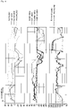
- the boom, the bucket, and the arm are operated. That is, when the boom, the bucket, and the arm are operated, working fluid discharged from the first main pump 310 is supplied to the boom cylinder 710, working fluid discharged from the second main pump 320 is supplied to the bucket cylinder 730 instead of the rotation motor 750, and working fluid discharged from the third main pump 330 is supplied to the arm cylinder 720.
- the working fluid discharged from the first main pump 310 moves along the first boom hydraulic line 611 to be supplied through the boom valve 510 to the boom cylinder 710.
- the working fluid discharged from the second main pump 320 moves along the bucket hydraulic line 630 to be supplied through the bucket valve 530 to the bucket cylinder 730.
- the rotation valve 550 blocks the working fluid supplied by the second main pump 320 to the rotation motor 750.
- the working fluid discharged from the third main pump 330 moves along the arm hydraulic line 620 to be supplied through the arm valve 530 to the arm cylinder 730.
- the first main pump 310 discharges working fluid according to an operation amount by which a user operates an operation device (not shown)
- the second main pump 320 discharges working fluid according to the required flow rate of the bucket cylinder 730
- the third main pump 330 discharges working fluid according to the required flow rate of the arm cylinder 720.
- each of the first main pump 310, the second main pump 320, and the third main pump 330 supplies working fluid to one driving device, the working fluid is not supplied to each driving device at an excessive pressure, thus minimizing the waste of energy.
- the first main pump 31 supplies the working fluid to the boom cylinder 71 and the bucket cylinder 73
- the second main pump 32 supplies working fluid to the arm 72 during the excavation operation.
- the second arm valve 52b is operated to replenish the arm cylinder 72 with the working fluid of the first main pump 31.
- a boom pilot, an arm pilot, a bucket pilot, and a rotation pilot mean signal pressure for driving or rotating the boom, the arm, and the bucket, respectively.
- the pressure of each of the boom valve, the arm valve, the bucket valve, and the rotation valve may be the pressure of working fluid supplied to each of the boom cylinder 71, the arm cylinder 72, the bucket cylinder 73, and the rotation motor 75.
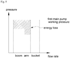
- the working-fluid discharge pressure of the first main pump 31 and the second main pump 32 is determined based on the driving device that requires the highest working pressure during excavation.
- the bucket cylinder 73 requires the highest working pressure.
- the first main pump 31 supplying working fluid to the bucket cylinder 73 discharges working fluid based on the working pressure of the bucket cylinder 73.
- a loss occurs in proportion to a hatched area in the graph of FIG. 5 in the first boom valve 51a and the first arm valve 52a supplying working fluid to the boom cylinder 71 and the arm cylinder 72 that are supplied with working fluid along with the bucket cylinder 73 from the first main pump 31 but are relatively low in working pressure.
- the first main pump 310, the second main pump 320, and the third main pump 330 supply working fluid to the boom cylinder 710, the bucket cylinder 720, and the arm cylinder 730, respectively, during excavation, thus minimizing the above-described energy loss.
- the boom, the rotation motor 750, and the bucket are operated. That is, when the boom, the rotation motor 750, and the bucket are operated, working fluid discharged from the first main pump 310 is supplied to the boom cylinder 710, working fluid discharged from the second main pump 320 is supplied to the rotation motor 750, and working fluid discharged from the third main pump 330 is supplied to the bucket cylinder 730 instead of the arm cylinder 720.
- the working fluid discharged from the first main pump 310 is moved along the first boom hydraulic line 611 to be supplied through the boom valve 510 to the boom cylinder 710.
- the working fluid discharged from the second main pump 320 is moved along the first rotation hydraulic line 651 to be supplied through the rotation valve 550 to the rotation motor 750.
- the working fluid discharged from the second main pump 320 according to the rotating direction of the rotation motor 750 may be moved along the second rotation hydraulic line 652 to be supplied through the rotation valve 550 to the rotation motor 750.
- the working fluid discharged from the third main pump 330 is moved along the arm bucket joining line 643 and the bucket hydraulic line 630 to be supplied through the bucket valve 530 to the bucket cylinder 730.
- the arm valve 520 blocks the working fluid supplied by the third main pump 330 to the arm cylinder 720.
- the first main pump 310 discharges working fluid according to an operation amount by which a user operates an operation device (not shown)
- the second main pump 320 discharges working fluid according to the required flow rate of the rotation motor 750
- the third main pump 330 discharges working fluid according to the required flow rate of the bucket cylinder 730.
- each of the first main pump 310, the second main pump 320, and the third main pump 330 basically supplies working fluid to one driving device, the working fluid is not supplied to each driving device at an excessive pressure, thus minimizing the waste of energy.
- the first main pump 31 supplies the working fluid to the boom cylinder 71 and the bucket cylinder 73
- the second main pump 32 supplies working fluid to the rotation motor 75 during the boom-up swing operation.
- the second boom valve 51b is operated, so that the second main pump 32 additionally supplies working fluid to the boom cylinder 71.
- the boom cylinder 71, the bucket cylinder 73, and the rotation motor 75 are mainly used during the boom-up swing operation of the conventional construction machine 10 shown in FIG. 1 .
- the working-fluid discharge pressure of the first main pump 31 and the second main pump 32 is determined based on the driving device that requires the highest working pressure during boom-up swing operation.
- the rotation motor 75 requires the highest working pressure.
- the second main pump 32 supplying working fluid to the rotation motor 75 discharges working fluid based on the working pressure of the rotation motor 75.
- the first main pump 310 discharges working fluid according to an operation amount by which a user operates an operation device (not shown), the second main pump 320 discharges working fluid according to the required flow rate of the rotation motor 750, and the third main pump 330 discharges working fluid according to the required flow rate of the bucket cylinder 730, thus minimizing the above-described energy loss.
- the boom, the rotation motor 750, the arm, and the bucket are operated.
- energy is regenerated using the inertial energy of rotation and the boom. That is, the first main pump 310 and the second main pump 320 may be operated with the working fluid discharged from the boom cylinder 710 and the rotation motor 750 to generate regeneration energy.
- the first main pump 310 controls the speed of the boom, and controls a rotation speed in the second main pump 320, and working fluid discharged from the third main pump 330 is supplied to the arm cylinder 710 and the bucket cylinder 730.
- the working fluid discharged from the third main pump 330 is supplied along the arm hydraulic line 620 through the arm valve 520 to the arm cylinder 720, and is moved along the arm bucket joining line 643 and the bucket hydraulic line 630 to be supplied through the bucket valve 530 to the bucket cylinder 730.
- the first main pump 310 controls the angle of the swash plate so as to control the speed of the boom cylinder 710 according to the operation amount by which a user operates the operation device (not shown)
- the second main pump 320 controls the angle of the swash plate so as to control the rotation speed of the rotation motor 750 according to the operation amount by which a user operates the operation device
- the third main pump 330 discharges working fluid according to the required flow rate of the boom cylinder 710 and the required flow rate of the bucket cylinder 730.
- the first main pump 310 and the second main pump 320 may recover the energy of the boom and rotation, thus improving energy efficiency.
- the first main pump 31 supplies the working fluid to the boom cylinder 71 and the bucket cylinder 73
- the second main pump 32 supplies working fluid to the arm cylinder 72 and the rotation motor 75.
- a relatively high working pressure is required in the rotation motor 75 and the boom cylinder 71 and a relatively low working pressure is required in the arm cylinder 72 and the bucket cylinder 73 during the dump operation of the conventional construction machine 10 shown in FIG. 1 . That is, a deviation between the working pressure of the boom cylinder 71 supplied with working fluid from the first main pump 31 and the working pressure of the bucket cylinder 73 is relatively large, and a deviation between the working pressure of the rotation motor 75 supplied with working fluid from the second main pump 32 and the working pressure of the arm cylinder 72 is also relatively large.
- the first main pump 31 discharges working fluid based on the working pressure of the boom cylinder 71 having a high working pressure among the boom cylinder 71 and the bucket cylinder 73 during the dump operation. Therefore, an energy loss occurs in the bucket valve 53 that supplies working fluid to the bucket cylinder 73 having a relatively low working pressure.
- the second main pump 32 discharges working fluid based on the working pressure of the rotation motor 75 having a high working pressure among the rotation motor 75 and the arm cylinder 72 during the dump operation. Therefore, an energy loss occurs in the first arm valve 52a that supplies working fluid to the arm cylinder 72 having a relatively low working pressure.
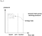
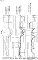
- a loss occurs in proportion to a hatched area in the graph of FIG. 11 in the first arm valve 52a that supplies working fluid discharged from the second main pump 32 to the arm cylinder 72. Further, regeneration energy that is generated during the boom and rotating process is converted into heat in the valve and then is dissipated.
- the first main pump 310 and the second main pump 320 recover energy during the boom and rotation, and the third main pump 330 discharges working fluid according to the required flow rate of the arm cylinder 720 and the required flow rate of the bucket cylinder 730, thus minimizing the above-described energy loss.
- the construction machine 101 uses three main pumps 310, 320, and 330, thus minimizing the energy loss when a plurality of driving devices are simultaneously operated.
- a construction machine can be used to minimize an energy loss when a plurality of driving devices are simultaneously operated.
- a construction machine can be used to improve energy utilization efficiency by recovering energy wasted from a driving device.
Landscapes
- Engineering & Computer Science (AREA)
- General Engineering & Computer Science (AREA)
- Mining & Mineral Resources (AREA)
- Civil Engineering (AREA)
- Structural Engineering (AREA)
- Physics & Mathematics (AREA)
- Fluid Mechanics (AREA)
- Mechanical Engineering (AREA)
- Chemical & Material Sciences (AREA)
- Analytical Chemistry (AREA)
- Operation Control Of Excavators (AREA)
- Fluid-Pressure Circuits (AREA)
Applications Claiming Priority (2)
| Application Number | Priority Date | Filing Date | Title |
|---|---|---|---|
| KR1020200024504A KR102763246B1 (ko) | 2020-02-27 | 2020-02-27 | 건설 기계 |
| PCT/KR2021/002445 WO2021172927A1 (fr) | 2020-02-27 | 2021-02-26 | Engin de chantier |
Publications (2)
| Publication Number | Publication Date |
|---|---|
| EP4112823A1 true EP4112823A1 (fr) | 2023-01-04 |
| EP4112823A4 EP4112823A4 (fr) | 2024-05-15 |
Family
ID=77490142
Family Applications (1)
| Application Number | Title | Priority Date | Filing Date |
|---|---|---|---|
| EP21761794.3A Pending EP4112823A4 (fr) | 2020-02-27 | 2021-02-26 | Engin de chantier |
Country Status (5)
| Country | Link |
|---|---|
| US (1) | US12054917B2 (fr) |
| EP (1) | EP4112823A4 (fr) |
| KR (1) | KR102763246B1 (fr) |
| CN (1) | CN115210432A (fr) |
| WO (1) | WO2021172927A1 (fr) |
Families Citing this family (4)
| Publication number | Priority date | Publication date | Assignee | Title |
|---|---|---|---|---|
| US20230356938A1 (en) * | 2022-05-05 | 2023-11-09 | Oshkosh Corporation | Hydraulic system for refuse vehicles |
| WO2025150731A1 (fr) * | 2024-01-09 | 2025-07-17 | 에이치디현대인프라코어 주식회사 | Engin de chantier |
| KR20250109052A (ko) * | 2024-01-09 | 2025-07-16 | 에이치디현대인프라코어 주식회사 | 건설 기계 |
| KR20250150925A (ko) | 2024-04-12 | 2025-10-21 | 에이치디현대인프라코어 주식회사 | 건설 기계 |
Family Cites Families (24)
| Publication number | Priority date | Publication date | Assignee | Title |
|---|---|---|---|---|
| US4369625A (en) * | 1979-06-27 | 1983-01-25 | Hitachi Construction Machinery Co., Ltd. | Drive system for construction machinery and method of controlling hydraulic circuit means thereof |
| JPS5754635A (en) * | 1980-09-16 | 1982-04-01 | Hitachi Constr Mach Co Ltd | Hydraulic circuit for civil engineering and construction equipment |
| DE60141137D1 (de) * | 2000-05-23 | 2010-03-11 | Kobelco Constr Machinery Ltd | Baumaschine |
| JP2004190845A (ja) * | 2002-12-13 | 2004-07-08 | Shin Caterpillar Mitsubishi Ltd | 作業機械の駆動装置 |
| JP4509877B2 (ja) * | 2005-06-29 | 2010-07-21 | キャタピラージャパン株式会社 | 作業機械のハイブリッドシステム |
| GB0614534D0 (en) * | 2006-07-21 | 2006-08-30 | Artemis Intelligent Power Ltd | Fluid power distribution and control system |
| JP5412077B2 (ja) * | 2008-10-01 | 2014-02-12 | キャタピラー エス エー アール エル | 油圧式作業機械の動力回生機構 |
| JP2010242796A (ja) * | 2009-04-01 | 2010-10-28 | Sumitomo (Shi) Construction Machinery Co Ltd | 建設機械用油圧制御回路 |
| KR101601979B1 (ko) * | 2009-12-24 | 2016-03-10 | 두산인프라코어 주식회사 | 건설장비의 펌프제어 작동시스템 |
| US9068578B2 (en) * | 2011-10-21 | 2015-06-30 | Caterpillar Inc. | Hydraulic system having flow combining capabilities |
| US20130098012A1 (en) * | 2011-10-21 | 2013-04-25 | Patrick Opdenbosch | Meterless hydraulic system having multi-circuit recuperation |
| JP2013245787A (ja) * | 2012-05-28 | 2013-12-09 | Hitachi Constr Mach Co Ltd | 作業機械の駆動装置 |
| CN104903595B (zh) * | 2013-01-08 | 2017-03-08 | 日立建机株式会社 | 工作机械的液压系统 |
| JP5961580B2 (ja) * | 2013-04-11 | 2016-08-02 | 日立建機株式会社 | 作業機械の駆動装置 |
| JP5973979B2 (ja) * | 2013-11-21 | 2016-08-23 | 日立建機株式会社 | 作業機械の駆動装置 |
| CN105658879B (zh) * | 2013-12-26 | 2018-03-27 | 斗山英维高株式会社 | 动臂能量再生控制回路及控制方法 |
| JP6235917B2 (ja) * | 2014-01-23 | 2017-11-22 | 川崎重工業株式会社 | 液圧駆動システム |
| WO2015198644A1 (fr) * | 2014-06-26 | 2015-12-30 | 日立建機株式会社 | Machine de travail |
| JP6555709B2 (ja) * | 2015-04-17 | 2019-08-07 | キャタピラー エス エー アール エル | 流体圧回路および作業機械 |
| KR101779860B1 (ko) * | 2015-10-28 | 2017-09-19 | 가부시키가이샤 고마쓰 세이사쿠쇼 | 건설 기계의 구동 장치 |
| JP6615138B2 (ja) * | 2017-03-01 | 2019-12-04 | 日立建機株式会社 | 建設機械の駆動装置 |
| CN107420357B (zh) * | 2017-07-21 | 2019-01-01 | 广西柳工机械股份有限公司 | 闭式液压系统 |
| CN108729492A (zh) * | 2018-06-06 | 2018-11-02 | 马鞍山松鹤信息科技有限公司 | 一种油液混合动力挖掘机势能回收方法 |
| JP6975102B2 (ja) * | 2018-06-26 | 2021-12-01 | 日立建機株式会社 | 建設機械 |
-
2020
- 2020-02-27 KR KR1020200024504A patent/KR102763246B1/ko active Active
-
2021
- 2021-02-26 US US17/802,351 patent/US12054917B2/en active Active
- 2021-02-26 EP EP21761794.3A patent/EP4112823A4/fr active Pending
- 2021-02-26 WO PCT/KR2021/002445 patent/WO2021172927A1/fr not_active Ceased
- 2021-02-26 CN CN202180017098.XA patent/CN115210432A/zh active Pending
Also Published As
| Publication number | Publication date |
|---|---|
| US20230096479A1 (en) | 2023-03-30 |
| EP4112823A4 (fr) | 2024-05-15 |
| WO2021172927A1 (fr) | 2021-09-02 |
| CN115210432A (zh) | 2022-10-18 |
| KR20210109334A (ko) | 2021-09-06 |
| KR102763246B1 (ko) | 2025-02-04 |
| US12054917B2 (en) | 2024-08-06 |
Similar Documents
| Publication | Publication Date | Title |
|---|---|---|
| US12054917B2 (en) | Construction machine | |
| US6962050B2 (en) | Hybrid machine with hydraulic drive device | |
| KR101942603B1 (ko) | 건설 기계 | |
| JP5858818B2 (ja) | 建設機械 | |
| CN103732927A (zh) | 具有贮存器和可变释放功能的能量回收系统 | |
| CN103282585A (zh) | 混合型挖掘机动臂驱动系统及其控制方法 | |
| US11542683B2 (en) | Construction machine | |
| KR102539054B1 (ko) | 유압 플라이휠 어큐뮬레이터, 유압 모터와 발전기를 이용한 에너지 회생 굴삭기 시스템 | |
| JPS6225882B2 (fr) | ||
| CN108953309B (zh) | 一种能量回收和再利用液压系统 | |
| JP2001248186A (ja) | 建設機械の制御装置 | |
| KR101791233B1 (ko) | 굴삭기의 파워매칭 시스템 및 그 제어방법 | |
| JP2008275101A (ja) | ハイブリッド式建設車両 | |
| JP4999404B2 (ja) | 油圧制御装置 | |
| JP2002349505A (ja) | 油圧アクチュエータ回路 | |
| JP4817974B2 (ja) | 建設機械の動力装置 | |
| KR20220013169A (ko) | 건설 기계 및 그 제어 방법 | |
| KR20220094921A (ko) | 건설 기계 | |
| KR20210126239A (ko) | 건설 기계 | |
| JP2007327526A (ja) | 建設機械の動力装置 | |
| US20260125877A1 (en) | Working machine | |
| KR20250150925A (ko) | 건설 기계 | |
| JP3472844B2 (ja) | 建設機械用油圧駆動装置並びにこれに用いる油圧駆動ユニット及び掘削ユニット | |
| KR20190092710A (ko) | 건설 기계 | |
| KR20250109052A (ko) | 건설 기계 |
Legal Events
| Date | Code | Title | Description |
|---|---|---|---|
| STAA | Information on the status of an ep patent application or granted ep patent |
Free format text: STATUS: THE INTERNATIONAL PUBLICATION HAS BEEN MADE |
|
| PUAI | Public reference made under article 153(3) epc to a published international application that has entered the european phase |
Free format text: ORIGINAL CODE: 0009012 |
|
| STAA | Information on the status of an ep patent application or granted ep patent |
Free format text: STATUS: REQUEST FOR EXAMINATION WAS MADE |
|
| 17P | Request for examination filed |
Effective date: 20220921 |
|
| AK | Designated contracting states |
Kind code of ref document: A1 Designated state(s): AL AT BE BG CH CY CZ DE DK EE ES FI FR GB GR HR HU IE IS IT LI LT LU LV MC MK MT NL NO PL PT RO RS SE SI SK SM TR |
|
| DAV | Request for validation of the european patent (deleted) | ||
| DAX | Request for extension of the european patent (deleted) | ||
| RAP3 | Party data changed (applicant data changed or rights of an application transferred) |
Owner name: HD HYUNDAI INFRACORE CO., LTD. |
|
| A4 | Supplementary search report drawn up and despatched |
Effective date: 20240416 |
|
| RIC1 | Information provided on ipc code assigned before grant |
Ipc: E02F 9/20 20060101ALI20240410BHEP Ipc: E02F 9/22 20060101AFI20240410BHEP |
|
| STAA | Information on the status of an ep patent application or granted ep patent |
Free format text: STATUS: EXAMINATION IS IN PROGRESS |
|
| 17Q | First examination report despatched |
Effective date: 20250818 |