EP4112835B1 - Profilgitter - Google Patents
Profilgitter Download PDFInfo
- Publication number
- EP4112835B1 EP4112835B1 EP21183134.2A EP21183134A EP4112835B1 EP 4112835 B1 EP4112835 B1 EP 4112835B1 EP 21183134 A EP21183134 A EP 21183134A EP 4112835 B1 EP4112835 B1 EP 4112835B1
- Authority
- EP
- European Patent Office
- Prior art keywords
- profiles
- profile
- grid
- primary
- connection clip
- Prior art date
- Legal status (The legal status is an assumption and is not a legal conclusion. Google has not performed a legal analysis and makes no representation as to the accuracy of the status listed.)
- Active
Links
Images



Classifications
-
- E—FIXED CONSTRUCTIONS
- E04—BUILDING
- E04B—GENERAL BUILDING CONSTRUCTIONS; WALLS, e.g. PARTITIONS; ROOFS; FLOORS; CEILINGS; INSULATION OR OTHER PROTECTION OF BUILDINGS
- E04B9/00—Ceilings; Construction of ceilings, e.g. false ceilings; Ceiling construction with regard to insulation
- E04B9/06—Ceilings; Construction of ceilings, e.g. false ceilings; Ceiling construction with regard to insulation characterised by constructional features of the supporting construction, e.g. cross section or material of framework members
- E04B9/12—Connections between non-parallel members of the supporting construction
- E04B9/16—Connections between non-parallel members of the supporting construction the members lying in different planes
-
- E—FIXED CONSTRUCTIONS
- E04—BUILDING
- E04B—GENERAL BUILDING CONSTRUCTIONS; WALLS, e.g. PARTITIONS; ROOFS; FLOORS; CEILINGS; INSULATION OR OTHER PROTECTION OF BUILDINGS
- E04B9/00—Ceilings; Construction of ceilings, e.g. false ceilings; Ceiling construction with regard to insulation
- E04B9/18—Means for suspending the supporting construction
-
- E—FIXED CONSTRUCTIONS
- E04—BUILDING
- E04B—GENERAL BUILDING CONSTRUCTIONS; WALLS, e.g. PARTITIONS; ROOFS; FLOORS; CEILINGS; INSULATION OR OTHER PROTECTION OF BUILDINGS
- E04B9/00—Ceilings; Construction of ceilings, e.g. false ceilings; Ceiling construction with regard to insulation
- E04B9/06—Ceilings; Construction of ceilings, e.g. false ceilings; Ceiling construction with regard to insulation characterised by constructional features of the supporting construction, e.g. cross section or material of framework members
- E04B9/065—Ceilings; Construction of ceilings, e.g. false ceilings; Ceiling construction with regard to insulation characterised by constructional features of the supporting construction, e.g. cross section or material of framework members comprising supporting beams having a folded cross-section
- E04B9/067—Ceilings; Construction of ceilings, e.g. false ceilings; Ceiling construction with regard to insulation characterised by constructional features of the supporting construction, e.g. cross section or material of framework members comprising supporting beams having a folded cross-section with inverted T-shaped cross-section
- E04B9/068—Ceilings; Construction of ceilings, e.g. false ceilings; Ceiling construction with regard to insulation characterised by constructional features of the supporting construction, e.g. cross section or material of framework members comprising supporting beams having a folded cross-section with inverted T-shaped cross-section with double web
Definitions
- the present invention relates to suspended ceiling systems and more particularly to a grid of profiles for a suspended ceiling system.
- Suspended ceiling systems are commonly used products in many different types of buildings in order to provide an aesthetically pleasing interior ceiling and/or for providing a desired functionality such as sound dampening and/or for supporting building equipment such as ventilation ducts or electrical wiring.
- a suspended ceiling system usually comprises a grid of profiles that supports a number of ceiling tiles, the grid of profiles being attached to a structural ceiling in the building.
- the ceiling tiles are typically made of a mineral fibre material, such as glass wool but other types of ceiling tiles are also produced.
- the grid of profiles usually comprises a number of profiles in the shape of main runners that extend in parallel, the main runners being connected to the structural ceiling.
- Cross runners may further be provided which extend between the main runners, providing increased rigidity to the grid of profiles.
- the cross runners may further facilitate achieving the desired spacing between the main runners.
- the object of the present invention is to provide a grid of profiles that mitigates some of the problems with prior art solutions.
- a grid of profiles for a suspended ceiling system comprising:
- the grid of profiles can thus be provided with secondary profiles that improve the rigidity of the grid of profiles.
- the connection clip facilitates flexible arrangement of the secondary profiles in relation to the primary profiles and reduces time required for installing the grid of profiles.
- the primary profile may be formed by a main runner or by a cross runner of the grid of profiles.
- connection clip may be snap fit mounted to the bulb portion of the primary profile, securing the connection clip in a reliable and quick manner to the primary profile at a position where a secondary profile is desired.
- the primary profile may have an inverted T-shaped profile with an upstanding web and laterally extending flanges, the bulb portion being arranged at a free end of the web.
- the secondary profile may further have an inverted T-shaped profile with an upstanding web and laterally extending flanges.
- the primary profile may be provided with a plurality of openings distributed along the longitudinal direction of the primary profile, each opening being configured for connection of an additional profile to the primary profile at the primary profile level.
- the grid of profiles may thus be provided with secondary profiles at a secondary profile level in addition to the additional profiles that are arranged on the primary profile level, facilitating providing increased rigidity to the grid of profiles.
- Each of the plurality of openings of the primary profile may have the same configuration as the opening of the projecting flange of the connection clip.
- the opening of the projecting flange may be aligned with one of the plurality of openings in the primary profile, allowing the secondary profiles to be arranged at a predetermined position on the primary profile and for instance over an additional profile.
- connection clip may comprise a registering element member configured to engage with one of the plurality of openings in the primary profile, thus facilitating that the connection clip can be aligned with one of the plurality of opening in the primary profile.
- connection clip may be made out of metal, for instance spring steel.
- the grid of profiles may be configured for supporting a ceiling tile by the primary profile.
- the grid of profiles may comprise a plurality of primary profiles and a plurality of secondary profiles.
- the grid of profiles may further comprise at least one suspension element connecting the primary profile to a structural ceiling.
- the opening of the projecting flange on the connection clip may be oriented such that the secondary profile extends perpendicularly in relation to the primary profile, providing a grid of profiles where openings between the primary profiles and the secondary profiles are rectangular.
- the opening of the projecting flange on the connection clip may further be oriented such that the secondary profile is vertically separated from the primary profile.
- the vertical separation allows greater vertical distance between the primary profile and the associated secondary profiles, which in certain application can be beneficial for instance to accommodate building utility equipment between the primary profile and the secondary profiles.
- the opening of the projecting flange on the connection clip may further be oriented such that the secondary profile and the primary profile vertically overlap.
- the secondary profiles may in such an application provide increased rigidity to the grid of profiles, as the secondary profiles can prevent excessive lateral movement of the primary profile.
- the opening of the projecting flange on the connection clip may be oriented such that the secondary profile extends at a vertical angle in relation to the primary profile.
- Figure 1 discloses a grid of profiles 10 for a suspended ceiling system.
- the grid of profiles 10 comprises a primary profile 100.
- the primary profile 100 may be a profile of the grid of profiles 10 that is connected to a structural ceiling 700 of a building in which the grid of profiles 10 is arranged, i.e. the primary profile may be a main runner in the grid of profiles.
- the primary profile 100 is the load bearing profile which supports the remaining components of the grid of profiles 10 directly or indirectly.
- the primary profile may be a cross runner in the grid of profiles.
- the grid of profiles 10 may be provided with suspension elements 600 connecting the grid of profiles 10 to the structural ceiling 700, preferably from the primary profiles 100.
- the suspension element 600 may be any type of element that is suitable for connecting the grid of profiles 10 to the ceiling 700 and may further be adjustable in order to achieve a level grid of profiles 10 etc.
- the remaining components of the grid of profiles are either directly or indirectly supported by the primary profiles 100, as mentioned. Naturally however, other components of the grid of profiles 10 than the primary profiles 100 may also be suspended from the structural ceiling 700 in a similar manner as for the primary profiles 100.
- the primary profile 100 may be provided with end connectors enabling interconnecting two primary profiles end-to-end such that they extend along a common longitudinal axis.
- the grid of profiles 10 may be configured to support a ceiling tile 500, preferably a plurality of ceiling tiles 500.
- the ceiling tiles 500 may be manufactured from a mineral fibre material such as glass wool.
- the ceiling tiles 500 may be arranged to be supported by the primary profiles 100 and/or additional profiles 400 arranged at the same level as the primary profiles 100. Alternatively, or in addition, ceiling tiles 500 may be provided supported by the secondary profiles 200.
- the primary profile 100 is preferably made from a metallic material such as steel or aluminium but may also be made from for instance a plastic material.
- the primary profile 100 is provided with a bulb portion 102 extending in a longitudinal direction of the primary profile 100.
- the bulb portion 102 is preferably arranged uppermost on the primary profile 100.
- the primary profile 100 may have an inverted T-shaped profile with an upstanding web 104 and laterally extending flanges 106, where the bulb portion 102 may be arranged at a free end of the web 104.
- the laterally extending flanges 106 may be configured for supporting the ceiling tiles 500.
- the grid of profiles 10 further comprises a secondary profile 200.
- the secondary profiles 200 provide rigidity to the grid of profiles 10 as they extend at an angle in relation to the primary profiles 100.
- the secondary profile 200 is preferably made from a metallic material such as steel or aluminium but may also be made from for instance a plastic material.
- the secondary profile 200 may have an inverted T-shaped profile with an upstanding web 204 and laterally extending flanges 206.
- the secondary profile 200 may comprise a bulb portion 208 at a free end of the upstanding web 204.
- the secondary profile 200 may be provided with the same profile as the primary profile 100.
- the secondary profile 200 may further comprise a connector 202 at an end of the secondary profile 200.
- the opposing end of the secondary profile 200 may be provided with a corresponding connector 202.
- the grid of profiles further comprises a connection clip 300.
- the connection clip 300 facilitates connection of the secondary profile 200 to the primary profile 100 and further allows that the secondary profile 200 can be arranged vertically offset from the primary profile 100.
- connection clip 200 comprises a base portion 302 configured for mounting to the bulb portion 102 of the primary profile and a projecting flange 304 provided with an opening 306.
- the connection clip is preferably made from a resilient material such as steel, e.g. spring steel. It may also be made from a plastic material.
- the projecting flange 304 may be configured to protrude in an upwardly direction or at an angle depending on the desired orientation of the secondary profile 200 in relation to the primary profile 100, as will be elaborated further on below.
- the opening 306 in the projecting flange is configured for reception of the connector 202 of the secondary profile 200 from a first side 304a of the projecting flange 304 and also a connector 202 of an opposing secondary profile 200 from a second side 304b of the projecting flange 304.
- the secondary profile 200 can thus be connected to the connection clip 300.
- the connector 202 is configured to snap-lock to the projecting flange 304 once inserted into the opening 306.
- the connector 202 may be configured for interlocking with a corresponding connector 202 when these are connected to the connection clip 300 from opposing sides.
- connection clip 300 is mounted to the bulb portion 102 of the primary profile 100 and the connector 202 of the secondary profile 200 is inserted into the opening 306 of projecting flange 304 such that the secondary profile is connected to the primary profile 100 via the connection clip 300 at a secondary profile 200 level which is different from a primary profile level in which the primary profile 100 extends.
- the level of the primary profiles 100 and the secondary profiles 200 respectively can be interpreted as the respective essentially horizontal plane on which the underside of the respective profiles 100, 200 extends in.
- the grid of profiles 10 can be made more rigid by the provision of the secondary profiles 200.
- the secondary profiles 200 may further facilitate achieving the desired spacing between the primary profiles 100.
- the connection clip 300 allows the positioning of the secondary profiles 200 in relation to the primary profiles 100 to be easily varied, as each connection clip 300 can be attached at any desired position along the length of the primary profile 100.
- the level of the secondary profiles 200 may be such that the secondary profiles are arranged entirely above the primary profiles 100, as is illustrated in Figures 1 and 2 .
- the opening 306 of the projecting flange 304 on the connection clip 300 may be oriented such that the secondary profile 200 extends perpendicularly in relation to the primary profile 100, thus forming a grid 10 having rectangular openings between the primary profiles 100 and the secondary profiles 200.
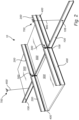
- FIG 2 is another embodiment illustrated in which the grid of profiles 10 is provided with additional profiles 400 extending in the primary profile 100 level.
- the primary profile 100 may be provided with a plurality of openings 108 distributed along the longitudinal direction of the primary profile 100. Each opening 108 being configured for connection of an additional profile 400 to the primary profile 100 at the primary profile level.
- the additional profiles 400 may form cross runners that extend in essentially the same level as the primary profiles 100.
- the combination of additional profiles 400 and the secondary profiles 200 provides high rigidity to the grid of profiles 10 and the flexibility of the placement of the connection clip 300 on the primary profiles 100 allows each secondary profile 200 to be arranged as desired, for instance where it can contribute the most to the improved rigidity.
- the secondary profiles 200 are arranged directly above the additional profiles 400.
- the secondary profiles 200 may be connected to the additional profiles 400 by means of connectors, such as clips, thereby improving the load bearing capacity of the additional profiles 400.
- the secondary profiles 200 does not have to be arranged above an additional profile 400 but can be arranged for instance between two additional profiles 400 or at any desired position along the length of the primary profile 100, giving great flexibility to reinforce the grid of profiles 10 where needed.
- Such an arrangement may also be used for securing a ceiling tile in the grid of profiles and may be used for instance in a venue for physical activities, such as a sports hall, having a suspended ceiling.
- the provision of a secondary profiles between two additional profiles, i.e. the secondary profile being arranged with an offset with regard to the additional profiles hereby forms an impact protection preventing displacement of the ceiling tile in the event of an impact to the suspended ceiling from below, such as from a ball hitting the ceiling tile.
- Each of the plurality of openings 108 of the primary profile 100 may have the same configuration as the opening 306 of the projecting flange 304 of the connection clip 300.
- the additional profiles 400 are preferably made from a metallic material such as steel or aluminium but may also be made from for instance a plastic material.
- the additional profiles 400 may have an inverted T-shaped profile with an upstanding web and laterally extending flanges and comprise a bulb portion at a free end of the upstanding web.
- the additional profiles 400 may be provided with the same profile as the primary profile 100.
- the additional profiles 400 and the secondary profiles 200 may be of the same type.
- connection clip 300 is shown in a perspective view.
- the connection clip 300 is preferably configured for snap fit mounting to the bulb portion of the 102 of the primary profiles 100.
- the connection clip 300 may for the purpose of snap fit mounting comprise snap fit members 310 extending from the base portion 302 in an upwardly direction, in the direction of the projecting flange 304.
- Two snap fit members 310 may be arranged at each lateral side of the base portion 302 and forming between them a narrowing space, as each snap fit member 310 extends upwards and towards the opposite snap fit member 310 on the same lateral side of the base portion 302.
- the snap fit members 310 will thus be pushed aside as the connection clip 300 is brought over the bulb portion 102 of the primary profile 100, whereafter the snap fit members 310 will resiliently return to a locking position after having passed over the bulb portion 102, whereby the snap lock members 310 will lockingly engage the side of the bulb portion 102 facing the laterally extending web 106 preventing the connection clip 300 to be removed from the primary profile 100.
- the snap fit members 310 In order to remove the connection clip 300, the snap fit members 310 must be bent open or the connection clip 300 slid longitudinally of an end of the primary profile 100.
- the base portion 302 of the connection clip 300 is configured to accommodate the bulb portion 102 and may thus be provided at least partly with a corresponding shape.
- the base portion 302 having a corresponding shape as the bulb portion 102 reduces play between the connection clip 300 and the primary profile 100, making the grid of profiles 10 more stable.
- the height of the projecting flange 304 along with the position of the opening 306 in relation to the base portion 302 may be different for different applications, in order to achieve a desired difference between the level of the primary profiles 100 and the level of the secondary profiles 200.
- the grid of profiles 10 may thus be adapted to accommodate a larger variety of ceiling tiles or other equipment.
- connection clip 300 is preferably made in one piece. It may be manufactured by a bending operation and/or stamping operation from a piece of suitably cut sheet material, such as sheet spring steel etc. It may also be made in a moulding operation for instance if the connection clip 300 is made from a plastic material.
- connection clip 300 In Figure 4 is an embodiment of the connection clip 300 shown, the embodiment shares the features with the embodiment of Figure 3 but is in addition provided with a registering element member 308.
- the registering element member 308 may be formed in one piece with the connection clip 300 or be attached thereto as a separate part.
- the registering element member 308 is configured to engage with one of the plurality of openings 108 in the primary profile 100 (shown in Figure 2 ), such that the connection clip 300 can be arranged aligned with a desired one of the openings 108. It is however to be realized that the registering element member 308 could also be used with any type of opening in the primary profile 100 into which the registering member 308 can fit.
- the registering element member 308 is preferably resilient such that it can resiliently move into one of the plurality of openings 108 as the connection clip 300 is moved along the primary profile 100.
- the registering member 308 may be formed as a resilient portion extending from the base portion 302 of the connection clip 300, the registering member 308 pushing against the web 104 of the primary profile 100 as the connection element is moved along the primary profile 100 until the registering member 308 reaches one of the openings 108 and resiliently moves into said opening and indicating that the connection clip 300 is aligned with said opening 108.
- Figures 5 and 6 show the connection clip 300 and the grid of profiles 10 in yet another embodiment.
- the embodiment illustrated in Figures 5 and 6 can be freely combined with the other embodiments disclosed herein unless explicitly stated otherwise.
- the opening 306 of the projecting flange 304 on the connection clip 300 is oriented such that the secondary profile 200 extends at an angle that is not perpendicular in relation to the primary profile 100. This allows the grid of profiles 10 to be adapted for instance if an obstacle prevents perpendicular extension of the secondary profiles 200.
- the opening 306 can be arranged such the angle between the secondary profiles 200 and the associated primary profile 100 is between 10° and 80°, preferably approximately 45°. It is conceivable that the connection clip 300 can be manufactured in a number of variations with different angles for the orientation of the opening 306, for instance in 10° degree intervals which allows an appropriate connection clip 300 to be selected for the application at hand.
- the opening 306 of the projecting flange 304 on the connection clip 300 is oriented such that the secondary profile 200 extends at a vertical angle in relation to the primary profile 100.
- the vertical angle of the secondary profile 200 in relation to the primary profile 100 provides improved flexibility to the grid of profiles 10, the secondary profiles 200 can extend such that they can connect to for instance a grid of profiles or to the building at a different level than that of the primary profiles 100 or the secondary profiles 200.
- the opening 306 can be arranged such the vertical angle between the secondary profiles 200 and the associated primary profile 100 is between 5° and 90°. It is conceivable that the connection clip 300 can be manufactured in a number of variations with different vertical angles for the orientation of the opening 306, for instance in 10° degree intervals which allows an appropriate connection clip 300 to be selected for the application at hand.
- the projecting flange 304 may further be configured such that it can be bent into the desired vertical angle by a technician during installation of the grid of profiles 10.
- Figure 9 shows an embodiment of the grid of profiles 10 in which the opening 306 of the projecting flange 304 on the connection clip 300 is oriented such that the secondary profile 200 and the primary profile 100 vertically overlap.
- the secondary profiles 200 may be provided with an engagement surface 210, the engagement surface 210 forming a space 212 accommodating at least the upper portion of the primary profile 100.
- the space 212 may further accommodate the base connection clip 300.
- the horizontal distance between two engagement surfaces 210 on two opposing secondary profiles 200 is preferably larger than the width of the bulb portion 102 of the primary profile 100 provided with the connection clip 300, such that the secondary profiles 200 will not press against each other and buckle for instance due to thermal expansion.
- the vertical overlap of the primary 100 and secondary 200 profiles provides increased rigidity to the grid of profiles 10, as a direct connection between the secondary profiles 200 and the primary profile 100 may be formed by the engagement surfaces 210 if the primary profile 100 moves laterally to either side. Movement of the secondary profiles 200 in the longitudinal direction can also be reduced, as the engagement surface 210 will contact the primary profile 100 and thus transfer forces directly to the primary profile 100 and not just via the connection clip 300.
Landscapes
- Engineering & Computer Science (AREA)
- Architecture (AREA)
- Physics & Mathematics (AREA)
- Electromagnetism (AREA)
- Civil Engineering (AREA)
- Structural Engineering (AREA)
- Clamps And Clips (AREA)
- Connection Of Plates (AREA)
Claims (16)
- Profilgitter (10) für ein abgehängtes Deckensystem, umfassend:ein Primärprofil (100), das mit einem Wulstabschnitt (102) versehen ist, der sich in einer Längsrichtung des Primärprofils (100) erstreckt,ein Sekundärprofil (200), das ein Verbindungsstück (202) an einem Ende des Sekundärprofils (200) umfasst, undeine Verbindungsklammer (300), die einen Basisabschnitt (302) umfasst, der zum Montieren an dem Wulstabschnitt (102) des Primärprofils eingerichtet ist, unddadurch gekennzeichnet, dass die Verbindungsklammer ferner einen vorstehenden Flansch (304) umfasst, der mit einer Öffnung (306) versehen ist, wobei die Öffnung (306) zur Aufnahme des Verbindungsstücks (202) des Sekundärprofils (200) von einer ersten Seite (304a) des vorstehenden Flansches (304) und auch eines Verbindungsstücks (202) eines gegenüberliegenden Sekundärprofils (200) von einer zweiten Seite (304b) des vorstehenden Flansches (304) eingerichtet ist,wobei die Verbindungsklammer (300) an dem Wulstabschnitt (102) des Primärprofils (100) montiert ist und das Verbindungsstück (202) des Sekundärprofils (200) in die Öffnung (306) des vorstehenden Flansches (304) derart eingesetzt ist, dass das Sekundärprofil mit dem Primärprofil (100) über die Verbindungsklammer (300) in einer Ebene des Sekundärprofils (200) verbunden ist, die sich von einer Ebene des Primärprofils unterscheidet, in der sich das Primärprofil (100) erstreckt.
- Profilgitter (10) nach Anspruch 1, wobei die Verbindungsklammer (300) an dem Wulstabschnitt (102) des Primärprofils (100) mit Schnappverbindung montiert ist.
- Profilgitter (10) nach Anspruch 1 oder 2, wobei das Primärprofil (100) ein umgekehrtes T-förmiges Profil mit einem aufrechten Steg (104) und sich seitlich erstreckenden Flanschen (106) aufweist, wobei der Wulstabschnitt (102) an einem freien Ende des Stegs (104) angeordnet ist.
- Profilgitter (10) nach einem der Ansprüche 1 bis 3, wobei das Sekundärprofil (200) ein umgekehrtes T-förmiges Profil mit einem aufrechten Steg (204) und sich seitlich erstreckenden Flanschen (206) aufweist.
- Profilgitter (10) nach einem der vorhergehenden Ansprüche, wobei das Primärprofil (100) mit mehreren Öffnungen (108) versehen ist, die entlang der Längsrichtung des Primärprofils (100) verteilt sind, wobei jede Öffnung (108) zur Verbindung eines zusätzlichen Profils (400) mit dem Primärprofil (100) auf der Ebene des Primärprofils eingerichtet ist.
- Profilgitter (10) nach Anspruch 5, wobei jede der mehreren Öffnungen (108) des Primärprofils (100) die gleiche Einrichtung aufweist wie die Öffnung (306) des vorstehenden Flansches (304) der Verbindungsklammer (300).
- Profilgitter (10) nach Anspruch 5 oder 6, wobei die Öffnung (306) des vorstehenden Flansches (304) mit einer der mehreren Öffnungen (108) in dem Primärprofil (100) ausgerichtet ist.
- Profilgitter (10) nach Anspruch 7, wobei der Basisabschnitt (302) der Verbindungsklammer (300) ein Passerelement (308) umfasst, das eingerichtet ist, um mit einer der mehreren Öffnungen (108) in dem Primärprofil (100) in Eingriff zu kommen.
- Profilgitter (10) nach einem der vorhergehenden Ansprüche, wobei die Verbindungsklammer (300) aus Metall hergestellt ist.
- Profilgitter (10) nach einem der vorhergehenden Ansprüche, wobei eine Deckenplatte (500) von dem Primärprofil (100) getragen ist.
- Profilgitter (10) nach einem der vorhergehenden Ansprüche, ferner umfassend mehrere Primärprofile (100) und mehrere Sekundärprofile (200).
- Profilgitter (10) nach einem der vorhergehenden Ansprüche, ferner umfassend mindestens ein Aufhängungselement (600), das das Primärprofil (100) mit einer Strukturdecke (700) verbindet.
- Profilgitter (10) nach einem der vorhergehenden Ansprüche, wobei die Öffnung (306) des vorstehenden Flansches (304) auf der Verbindungsklammer (300) derart ausgerichtet ist, dass sich das Sekundärprofil (200) senkrecht zu dem Primärprofil (100) erstreckt.
- Profilgitter (10) nach einem der vorhergehenden Ansprüche, wobei die Öffnung (306) des vorstehenden Flansches (304) auf der Verbindungsklammer (300) derart ausgerichtet ist, dass das Sekundärprofil (200) vertikal von dem Primärprofil (100) getrennt ist.
- Profilgitter (10) nach einem der Ansprüche 1 bis 13, wobei die Öffnung (306) des vorstehenden Flansches (304) auf der Verbindungsklammer (300) derart ausgerichtet ist, dass sich das Sekundärprofil (200) und das Primärprofil (100) vertikal überlappen.
- Profilgitter (10) nach einem der vorhergehenden Ansprüche, wobei die Öffnung (306) des vorstehenden Flansches (304) auf der Verbindungsklammer (300) derart ausgerichtet ist, dass sich das Sekundärprofil (200) in einem vertikalen Winkel in Bezug auf das Primärprofil (100) erstreckt.
Priority Applications (4)
| Application Number | Priority Date | Filing Date | Title |
|---|---|---|---|
| EP21183134.2A EP4112835B1 (de) | 2021-07-01 | 2021-07-01 | Profilgitter |
| CA3220950A CA3220950A1 (en) | 2021-07-01 | 2022-06-14 | A grid of profiles |
| US18/574,285 US12644280B2 (en) | 2021-07-01 | 2022-06-14 | Grid of profiles |
| PCT/EP2022/066156 WO2023274715A1 (en) | 2021-07-01 | 2022-06-14 | A grid of profiles |
Applications Claiming Priority (1)
| Application Number | Priority Date | Filing Date | Title |
|---|---|---|---|
| EP21183134.2A EP4112835B1 (de) | 2021-07-01 | 2021-07-01 | Profilgitter |
Publications (3)
| Publication Number | Publication Date |
|---|---|
| EP4112835A1 EP4112835A1 (de) | 2023-01-04 |
| EP4112835B1 true EP4112835B1 (de) | 2024-05-15 |
| EP4112835C0 EP4112835C0 (de) | 2024-05-15 |
Family
ID=77021043
Family Applications (1)
| Application Number | Title | Priority Date | Filing Date |
|---|---|---|---|
| EP21183134.2A Active EP4112835B1 (de) | 2021-07-01 | 2021-07-01 | Profilgitter |
Country Status (4)
| Country | Link |
|---|---|
| US (1) | US12644280B2 (de) |
| EP (1) | EP4112835B1 (de) |
| CA (1) | CA3220950A1 (de) |
| WO (1) | WO2023274715A1 (de) |
Family Cites Families (43)
| Publication number | Priority date | Publication date | Assignee | Title |
|---|---|---|---|---|
| US2303269A (en) * | 1940-02-10 | 1942-11-24 | Goss William | Support for suspended ceilings |
| US2499278A (en) * | 1945-11-16 | 1950-02-28 | Anders C Olsen | Fastening element for wall and ceiling constructions |
| US3496690A (en) * | 1967-04-17 | 1970-02-24 | Chicago Metallic Sash Co | Main runner part |
| US3774366A (en) * | 1970-11-17 | 1973-11-27 | W Baker | Box beam structures and connections for beam-supported structures |
| US3816880A (en) * | 1972-12-04 | 1974-06-18 | Prudential Lighting Corp | Multiple detent retaining clip |
| US3898782A (en) * | 1974-01-04 | 1975-08-12 | Lightolier Inc | Integrated ceiling system |
| DE2414573C2 (de) * | 1974-03-26 | 1975-11-06 | Paul 6456 Langenselbold Gutermuth | Unterdecke zur Abschirmung tragender Decken von Räumen |
| US4041668A (en) * | 1975-12-04 | 1977-08-16 | Chicago Metallic Corporation | Clip structure for a concealed grid structure of a suspended ceiling |
| US4126971A (en) * | 1976-08-19 | 1978-11-28 | Eclipse Mfg. Inc. | Fixture hanging assembly |
| JPS6117131Y2 (de) * | 1980-05-21 | 1986-05-26 | ||
| US4541216A (en) * | 1981-06-29 | 1985-09-17 | Environmental Interiors, Inc. | Suspended ceiling system |
| AU566622B2 (en) * | 1983-01-21 | 1987-10-22 | Intalite International N.V. | Clip for suspended ceiling |
| EP0206146B1 (de) * | 1985-06-26 | 1989-03-15 | Hunter Douglas Industries B.V. | Ünterkonstruktion für Bauwerksverkleidungen |
| US4723749A (en) * | 1986-05-19 | 1988-02-09 | Erico International Corporation | Channel clip |
| US4920719A (en) * | 1989-03-13 | 1990-05-01 | Armstrong World Industries, Inc. | Method and apparatus of positioning a new ceiling over an existing ceiling |
| JP3172927B2 (ja) * | 1992-08-28 | 2001-06-04 | ナカ工業株式会社 | 天井バーの吊持装置 |
| SE504079C2 (sv) * | 1995-05-03 | 1996-11-04 | Ecophon Ab | Anordning för hopkoppling av profiler |
| US5823484A (en) * | 1996-09-30 | 1998-10-20 | Mcdonnell Douglas Corporation | Hose pipe, or conduit snap-in support system |
| US6230464B1 (en) * | 2000-03-02 | 2001-05-15 | 3244 Corporation | Electrical box hanger |
| KR100536001B1 (ko) * | 2003-11-29 | 2005-12-12 | 희 철 남 | 건축물의 천정판 설치용 인써트 |
| US20060005495A1 (en) * | 2004-07-12 | 2006-01-12 | Wilfried Stessel | Concealed accessible suspended ceiling system |
| CA2518294C (en) * | 2004-09-07 | 2009-06-23 | Chicago Metallic Corporation | Seismic perimeter clip for suspended ceiling grid |
| KR100676960B1 (ko) * | 2005-06-15 | 2007-02-01 | 김권희 | 다양한 형상의 천장판넬 조립구조 |
| US8657130B2 (en) * | 2005-07-07 | 2014-02-25 | Parallax Group International, Llc | Modular overhead storage |
| US7264214B2 (en) * | 2005-09-19 | 2007-09-04 | Kofulso Co., Ltd. | Stock bar and T-bar coupling structure for mounting sprinkler |
| DK2126238T3 (da) * | 2006-12-27 | 2012-07-23 | Rockwool Int | Loftophængningssystem |
| US8336843B2 (en) * | 2009-07-16 | 2012-12-25 | Usg Interiors, Llc | Secure locking attachment device useful with suspended ceiling systems |
| US8474200B2 (en) * | 2010-03-11 | 2013-07-02 | Decoustics Limited | Suspended ceiling grid system |
| FR2966850B1 (fr) * | 2010-10-29 | 2013-07-19 | Plafometal | Connecteur pour ossature metallique de plafond suspendu et plafond l'utilisant. |
| CA2816760C (en) * | 2010-11-01 | 2019-06-04 | Armstrong World Industries, Inc. | Suspended ceiling system, securing members, and process of installing a suspended ceiling system |
| ES2552161T3 (es) * | 2011-09-23 | 2015-11-26 | Rockwool International A/S | Sistema de soporte para el montaje de una rejilla de panel o estructura de soporte de pared |
| NL2011556C2 (nl) * | 2013-10-04 | 2015-04-09 | Saint Gobain Acoustical Products Internat B V | Plafondophangsysteem, profiel en werkwijze. |
| US9279253B1 (en) * | 2014-11-14 | 2016-03-08 | Awi Licensing Company | Ceiling system |
| US10405942B2 (en) * | 2015-10-07 | 2019-09-10 | Sld Technology, Inc. | Airframe system and method of controlling airflow |
| US10106982B2 (en) * | 2017-03-13 | 2018-10-23 | Rockwool International A/S | High strength grid member for suspended ceilings |
| US11525261B2 (en) * | 2018-03-21 | 2022-12-13 | Worthington Armstrong Venture | Suspended ceiling connectors for unique grid designs |
| US10947725B2 (en) * | 2018-11-08 | 2021-03-16 | Worthington Armstrong Venture | Suspended ceiling pass through grid connector |
| PL3969683T3 (pl) * | 2019-05-14 | 2025-09-29 | Rockwool A/S | System montażu sufitu podwieszanego |
| NL2023698B1 (en) * | 2019-08-23 | 2021-05-04 | Saint Gobain Acoustical Products Int B V | Ceiling suspension system having a coupling bracket with resilient retaining tabs. |
| MX2022005176A (es) * | 2019-11-05 | 2022-06-08 | Armstrong World Ind Inc | Sistema de techo acustico. |
| US11220819B2 (en) * | 2020-03-12 | 2022-01-11 | Usg Interiors, Llc | Triple-lock main tee splice |
| KR102470244B1 (ko) * | 2020-04-22 | 2022-11-23 | 정민시 | 천장 경량철골 구조 메인 캐리어의 장착수단 |
| WO2022040721A1 (en) * | 2020-08-28 | 2022-03-03 | Saidian Sasan | Structural soffit restraint arrangements |
-
2021
- 2021-07-01 EP EP21183134.2A patent/EP4112835B1/de active Active
-
2022
- 2022-06-14 CA CA3220950A patent/CA3220950A1/en active Pending
- 2022-06-14 US US18/574,285 patent/US12644280B2/en active Active
- 2022-06-14 WO PCT/EP2022/066156 patent/WO2023274715A1/en not_active Ceased
Also Published As
| Publication number | Publication date |
|---|---|
| US20240279925A1 (en) | 2024-08-22 |
| CA3220950A1 (en) | 2023-01-05 |
| EP4112835C0 (de) | 2024-05-15 |
| US12644280B2 (en) | 2026-06-02 |
| EP4112835A1 (de) | 2023-01-04 |
| WO2023274715A1 (en) | 2023-01-05 |
Similar Documents
| Publication | Publication Date | Title |
|---|---|---|
| US7779593B2 (en) | Wall angle with pre-punched locating tabs | |
| US7614195B2 (en) | Suspended ceiling grid network utilizing seismic separation joint clips | |
| US9086175B2 (en) | Support collar for long articles, in particular cables, pipes, and/or the like | |
| US11274440B2 (en) | Suspension ceiling support clip | |
| US20160053488A1 (en) | Free span ceiling grid system | |
| JP2002233024A (ja) | 長尺ビルディングサービス供給手段の支持手段 | |
| EP2951366B1 (de) | Klammer für umfangsverkleidung | |
| WO1999022096A1 (en) | Flooring system | |
| SK27296A3 (en) | Low profile raised panel flooring with metal support structure | |
| KR20080109057A (ko) | 슬래브 거푸집 시스템 | |
| US4598521A (en) | Suspension ceiling grid with end connector | |
| US11261601B2 (en) | Cross runner connector and cross runner connector arrangement for a suspended ceiling system | |
| US20240279925A1 (en) | A grid of profiles | |
| EP3862501B1 (de) | Sekundärer profilverbinder für ein hängedeckensystem | |
| KR101221964B1 (ko) | 엠바 조립체 | |
| EP4431676A1 (de) | Deckkantenstütze | |
| AU2021295547A1 (en) | Fastening apparatus for fastening solar modules | |
| US10619361B2 (en) | Transition profile between flooring elements | |
| EP1475559B1 (de) | Stützkonsole für Kabelträgersysteme und Zubehör dafür | |
| KR102303740B1 (ko) | 케이블 트레이 | |
| CA1188472A (en) | Suspension ceiling grid with end connector | |
| EP4291788A1 (de) | Oberleitungsschienenbefestigung | |
| EP1885965B1 (de) | Wandanordnung | |
| EP4492676A1 (de) | Vorrichtung zur befestigung mindestens eines solarpaneels auf einem dach | |
| EP4112834B1 (de) | Raster von profilen und verfahren zur demontage eines rasters von profilen |
Legal Events
| Date | Code | Title | Description |
|---|---|---|---|
| PUAI | Public reference made under article 153(3) epc to a published international application that has entered the european phase |
Free format text: ORIGINAL CODE: 0009012 |
|
| STAA | Information on the status of an ep patent application or granted ep patent |
Free format text: STATUS: THE APPLICATION HAS BEEN PUBLISHED |
|
| AK | Designated contracting states |
Kind code of ref document: A1 Designated state(s): AL AT BE BG CH CY CZ DE DK EE ES FI FR GB GR HR HU IE IS IT LI LT LU LV MC MK MT NL NO PL PT RO RS SE SI SK SM TR |
|
| STAA | Information on the status of an ep patent application or granted ep patent |
Free format text: STATUS: REQUEST FOR EXAMINATION WAS MADE |
|
| 17P | Request for examination filed |
Effective date: 20230627 |
|
| RBV | Designated contracting states (corrected) |
Designated state(s): AL AT BE BG CH CY CZ DE DK EE ES FI FR GB GR HR HU IE IS IT LI LT LU LV MC MK MT NL NO PL PT RO RS SE SI SK SM TR |
|
| GRAP | Despatch of communication of intention to grant a patent |
Free format text: ORIGINAL CODE: EPIDOSNIGR1 |
|
| STAA | Information on the status of an ep patent application or granted ep patent |
Free format text: STATUS: GRANT OF PATENT IS INTENDED |
|
| INTG | Intention to grant announced |
Effective date: 20231214 |
|
| GRAS | Grant fee paid |
Free format text: ORIGINAL CODE: EPIDOSNIGR3 |
|
| GRAA | (expected) grant |
Free format text: ORIGINAL CODE: 0009210 |
|
| STAA | Information on the status of an ep patent application or granted ep patent |
Free format text: STATUS: THE PATENT HAS BEEN GRANTED |
|
| AK | Designated contracting states |
Kind code of ref document: B1 Designated state(s): AL AT BE BG CH CY CZ DE DK EE ES FI FR GB GR HR HU IE IS IT LI LT LU LV MC MK MT NL NO PL PT RO RS SE SI SK SM TR |
|
| REG | Reference to a national code |
Ref country code: CH Ref legal event code: EP |
|
| REG | Reference to a national code |
Ref country code: IE Ref legal event code: FG4D |
|
| REG | Reference to a national code |
Ref country code: DE Ref legal event code: R096 Ref document number: 602021013233 Country of ref document: DE |
|
| U01 | Request for unitary effect filed |
Effective date: 20240522 |
|
| U07 | Unitary effect registered |
Designated state(s): AT BE BG DE DK EE FI FR IT LT LU LV MT NL PT SE SI Effective date: 20240612 |
|
| U20 | Renewal fee for the european patent with unitary effect paid |
Year of fee payment: 4 Effective date: 20240617 |
|
| PG25 | Lapsed in a contracting state [announced via postgrant information from national office to epo] |
Ref country code: IS Free format text: LAPSE BECAUSE OF FAILURE TO SUBMIT A TRANSLATION OF THE DESCRIPTION OR TO PAY THE FEE WITHIN THE PRESCRIBED TIME-LIMIT Effective date: 20240915 |
|
| PG25 | Lapsed in a contracting state [announced via postgrant information from national office to epo] |
Ref country code: HR Free format text: LAPSE BECAUSE OF FAILURE TO SUBMIT A TRANSLATION OF THE DESCRIPTION OR TO PAY THE FEE WITHIN THE PRESCRIBED TIME-LIMIT Effective date: 20240515 |
|
| PG25 | Lapsed in a contracting state [announced via postgrant information from national office to epo] |
Ref country code: GR Free format text: LAPSE BECAUSE OF FAILURE TO SUBMIT A TRANSLATION OF THE DESCRIPTION OR TO PAY THE FEE WITHIN THE PRESCRIBED TIME-LIMIT Effective date: 20240816 |
|
| PG25 | Lapsed in a contracting state [announced via postgrant information from national office to epo] |
Ref country code: ES Free format text: LAPSE BECAUSE OF FAILURE TO SUBMIT A TRANSLATION OF THE DESCRIPTION OR TO PAY THE FEE WITHIN THE PRESCRIBED TIME-LIMIT Effective date: 20240515 |
|
| PG25 | Lapsed in a contracting state [announced via postgrant information from national office to epo] |
Ref country code: PL Free format text: LAPSE BECAUSE OF FAILURE TO SUBMIT A TRANSLATION OF THE DESCRIPTION OR TO PAY THE FEE WITHIN THE PRESCRIBED TIME-LIMIT Effective date: 20240515 |
|
| PG25 | Lapsed in a contracting state [announced via postgrant information from national office to epo] |
Ref country code: PL Free format text: LAPSE BECAUSE OF FAILURE TO SUBMIT A TRANSLATION OF THE DESCRIPTION OR TO PAY THE FEE WITHIN THE PRESCRIBED TIME-LIMIT Effective date: 20240515 Ref country code: NO Free format text: LAPSE BECAUSE OF FAILURE TO SUBMIT A TRANSLATION OF THE DESCRIPTION OR TO PAY THE FEE WITHIN THE PRESCRIBED TIME-LIMIT Effective date: 20240815 Ref country code: IS Free format text: LAPSE BECAUSE OF FAILURE TO SUBMIT A TRANSLATION OF THE DESCRIPTION OR TO PAY THE FEE WITHIN THE PRESCRIBED TIME-LIMIT Effective date: 20240915 Ref country code: HR Free format text: LAPSE BECAUSE OF FAILURE TO SUBMIT A TRANSLATION OF THE DESCRIPTION OR TO PAY THE FEE WITHIN THE PRESCRIBED TIME-LIMIT Effective date: 20240515 Ref country code: GR Free format text: LAPSE BECAUSE OF FAILURE TO SUBMIT A TRANSLATION OF THE DESCRIPTION OR TO PAY THE FEE WITHIN THE PRESCRIBED TIME-LIMIT Effective date: 20240816 Ref country code: ES Free format text: LAPSE BECAUSE OF FAILURE TO SUBMIT A TRANSLATION OF THE DESCRIPTION OR TO PAY THE FEE WITHIN THE PRESCRIBED TIME-LIMIT Effective date: 20240515 Ref country code: RS Free format text: LAPSE BECAUSE OF FAILURE TO SUBMIT A TRANSLATION OF THE DESCRIPTION OR TO PAY THE FEE WITHIN THE PRESCRIBED TIME-LIMIT Effective date: 20240815 |
|
| PG25 | Lapsed in a contracting state [announced via postgrant information from national office to epo] |
Ref country code: CZ Free format text: LAPSE BECAUSE OF FAILURE TO SUBMIT A TRANSLATION OF THE DESCRIPTION OR TO PAY THE FEE WITHIN THE PRESCRIBED TIME-LIMIT Effective date: 20240515 |
|
| PG25 | Lapsed in a contracting state [announced via postgrant information from national office to epo] |
Ref country code: SK Free format text: LAPSE BECAUSE OF FAILURE TO SUBMIT A TRANSLATION OF THE DESCRIPTION OR TO PAY THE FEE WITHIN THE PRESCRIBED TIME-LIMIT Effective date: 20240515 Ref country code: RO Free format text: LAPSE BECAUSE OF FAILURE TO SUBMIT A TRANSLATION OF THE DESCRIPTION OR TO PAY THE FEE WITHIN THE PRESCRIBED TIME-LIMIT Effective date: 20240515 |
|
| PG25 | Lapsed in a contracting state [announced via postgrant information from national office to epo] |
Ref country code: SM Free format text: LAPSE BECAUSE OF FAILURE TO SUBMIT A TRANSLATION OF THE DESCRIPTION OR TO PAY THE FEE WITHIN THE PRESCRIBED TIME-LIMIT Effective date: 20240515 |
|
| PG25 | Lapsed in a contracting state [announced via postgrant information from national office to epo] |
Ref country code: SM Free format text: LAPSE BECAUSE OF FAILURE TO SUBMIT A TRANSLATION OF THE DESCRIPTION OR TO PAY THE FEE WITHIN THE PRESCRIBED TIME-LIMIT Effective date: 20240515 Ref country code: SK Free format text: LAPSE BECAUSE OF FAILURE TO SUBMIT A TRANSLATION OF THE DESCRIPTION OR TO PAY THE FEE WITHIN THE PRESCRIBED TIME-LIMIT Effective date: 20240515 Ref country code: RO Free format text: LAPSE BECAUSE OF FAILURE TO SUBMIT A TRANSLATION OF THE DESCRIPTION OR TO PAY THE FEE WITHIN THE PRESCRIBED TIME-LIMIT Effective date: 20240515 Ref country code: CZ Free format text: LAPSE BECAUSE OF FAILURE TO SUBMIT A TRANSLATION OF THE DESCRIPTION OR TO PAY THE FEE WITHIN THE PRESCRIBED TIME-LIMIT Effective date: 20240515 |
|
| PG25 | Lapsed in a contracting state [announced via postgrant information from national office to epo] |
Ref country code: MC Free format text: LAPSE BECAUSE OF FAILURE TO SUBMIT A TRANSLATION OF THE DESCRIPTION OR TO PAY THE FEE WITHIN THE PRESCRIBED TIME-LIMIT Effective date: 20240515 |
|
| REG | Reference to a national code |
Ref country code: DE Ref legal event code: R097 Ref document number: 602021013233 Country of ref document: DE |
|
| REG | Reference to a national code |
Ref country code: CH Ref legal event code: PL |
|
| PLBE | No opposition filed within time limit |
Free format text: ORIGINAL CODE: 0009261 |
|
| STAA | Information on the status of an ep patent application or granted ep patent |
Free format text: STATUS: NO OPPOSITION FILED WITHIN TIME LIMIT |
|
| 26N | No opposition filed |
Effective date: 20250218 |
|
| PG25 | Lapsed in a contracting state [announced via postgrant information from national office to epo] |
Ref country code: CH Free format text: LAPSE BECAUSE OF NON-PAYMENT OF DUE FEES Effective date: 20240731 |
|
| U20 | Renewal fee for the european patent with unitary effect paid |
Year of fee payment: 5 Effective date: 20250613 |
|
| PG25 | Lapsed in a contracting state [announced via postgrant information from national office to epo] |
Ref country code: IE Free format text: LAPSE BECAUSE OF NON-PAYMENT OF DUE FEES Effective date: 20240701 |
|
| PG25 | Lapsed in a contracting state [announced via postgrant information from national office to epo] |
Ref country code: CY Free format text: LAPSE BECAUSE OF FAILURE TO SUBMIT A TRANSLATION OF THE DESCRIPTION OR TO PAY THE FEE WITHIN THE PRESCRIBED TIME-LIMIT; INVALID AB INITIO Effective date: 20210701 |
|
| PG25 | Lapsed in a contracting state [announced via postgrant information from national office to epo] |
Ref country code: HU Free format text: LAPSE BECAUSE OF FAILURE TO SUBMIT A TRANSLATION OF THE DESCRIPTION OR TO PAY THE FEE WITHIN THE PRESCRIBED TIME-LIMIT; INVALID AB INITIO Effective date: 20210701 |
|
| GBPC | Gb: european patent ceased through non-payment of renewal fee |
Effective date: 20250701 |
|
| PG25 | Lapsed in a contracting state [announced via postgrant information from national office to epo] |
Ref country code: GB Free format text: LAPSE BECAUSE OF NON-PAYMENT OF DUE FEES Effective date: 20250701 |
|
| PG25 | Lapsed in a contracting state [announced via postgrant information from national office to epo] |
Ref country code: TR Free format text: LAPSE BECAUSE OF FAILURE TO SUBMIT A TRANSLATION OF THE DESCRIPTION OR TO PAY THE FEE WITHIN THE PRESCRIBED TIME-LIMIT Effective date: 20240515 |