EP4112840A1 - Système de plancher modulaire - Google Patents
Système de plancher modulaire Download PDFInfo
- Publication number
- EP4112840A1 EP4112840A1 EP22191194.4A EP22191194A EP4112840A1 EP 4112840 A1 EP4112840 A1 EP 4112840A1 EP 22191194 A EP22191194 A EP 22191194A EP 4112840 A1 EP4112840 A1 EP 4112840A1
- Authority
- EP
- European Patent Office
- Prior art keywords
- mat
- flange
- layer
- fitting
- modular
- Prior art date
- Legal status (The legal status is an assumption and is not a legal conclusion. Google has not performed a legal analysis and makes no representation as to the accuracy of the status listed.)
- Granted
Links
Images





Classifications
-
- E—FIXED CONSTRUCTIONS
- E04—BUILDING
- E04F—FINISHING WORK ON BUILDINGS, e.g. STAIRS, FLOORS
- E04F15/00—Flooring
- E04F15/02—Flooring or floor layers composed of a number of similar elements
- E04F15/02005—Construction of joints, e.g. dividing strips
- E04F15/02033—Joints with beveled or recessed upper edges
-
- E—FIXED CONSTRUCTIONS
- E01—CONSTRUCTION OF ROADS, RAILWAYS, OR BRIDGES
- E01C—CONSTRUCTION OF, OR SURFACES FOR, ROADS, SPORTS GROUNDS, OR THE LIKE; MACHINES OR AUXILIARY TOOLS FOR CONSTRUCTION OR REPAIR
- E01C5/00—Pavings made of prefabricated single units
- E01C5/20—Pavings made of prefabricated single units made of units of plastics, e.g. concrete with plastics, linoleum
-
- E—FIXED CONSTRUCTIONS
- E01—CONSTRUCTION OF ROADS, RAILWAYS, OR BRIDGES
- E01C—CONSTRUCTION OF, OR SURFACES FOR, ROADS, SPORTS GROUNDS, OR THE LIKE; MACHINES OR AUXILIARY TOOLS FOR CONSTRUCTION OR REPAIR
- E01C9/00—Special pavings; Pavings for special parts of roads or airfields
- E01C9/08—Temporary pavings
- E01C9/086—Temporary pavings made of concrete, wood, bitumen, rubber or synthetic material or a combination thereof
-
- E—FIXED CONSTRUCTIONS
- E04—BUILDING
- E04B—GENERAL BUILDING CONSTRUCTIONS; WALLS, e.g. PARTITIONS; ROOFS; FLOORS; CEILINGS; INSULATION OR OTHER PROTECTION OF BUILDINGS
- E04B5/00—Floors; Floor construction with regard to insulation; Connections specially adapted therefor
- E04B5/02—Load-carrying floor structures formed substantially of prefabricated units
- E04B5/023—Separate connecting devices for prefabricated floor-slabs
-
- E—FIXED CONSTRUCTIONS
- E04—BUILDING
- E04B—GENERAL BUILDING CONSTRUCTIONS; WALLS, e.g. PARTITIONS; ROOFS; FLOORS; CEILINGS; INSULATION OR OTHER PROTECTION OF BUILDINGS
- E04B5/00—Floors; Floor construction with regard to insulation; Connections specially adapted therefor
- E04B5/43—Floor structures of extraordinary design; Features relating to the elastic stability; Floor structures specially designed for resting on columns only, e.g. mushroom floors
-
- E—FIXED CONSTRUCTIONS
- E04—BUILDING
- E04F—FINISHING WORK ON BUILDINGS, e.g. STAIRS, FLOORS
- E04F15/00—Flooring
- E04F15/02—Flooring or floor layers composed of a number of similar elements
- E04F15/02038—Flooring or floor layers composed of a number of similar elements characterised by tongue and groove connections between neighbouring flooring elements
-
- E—FIXED CONSTRUCTIONS
- E04—BUILDING
- E04F—FINISHING WORK ON BUILDINGS, e.g. STAIRS, FLOORS
- E04F15/00—Flooring
- E04F15/02—Flooring or floor layers composed of a number of similar elements
- E04F15/02044—Separate elements for fastening to an underlayer
-
- E—FIXED CONSTRUCTIONS
- E04—BUILDING
- E04F—FINISHING WORK ON BUILDINGS, e.g. STAIRS, FLOORS
- E04F15/00—Flooring
- E04F15/02—Flooring or floor layers composed of a number of similar elements
- E04F15/02172—Floor elements with an anti-skid main surface, other than with grooves
-
- E—FIXED CONSTRUCTIONS
- E04—BUILDING
- E04F—FINISHING WORK ON BUILDINGS, e.g. STAIRS, FLOORS
- E04F15/00—Flooring
- E04F15/02—Flooring or floor layers composed of a number of similar elements
- E04F15/10—Flooring or floor layers composed of a number of similar elements of other materials, e.g. fibrous or chipped materials, organic plastics, magnesite tiles, hardboard, or with a top layer of other materials
- E04F15/105—Flooring or floor layers composed of a number of similar elements of other materials, e.g. fibrous or chipped materials, organic plastics, magnesite tiles, hardboard, or with a top layer of other materials of organic plastics with or without reinforcements or filling materials
-
- E—FIXED CONSTRUCTIONS
- E04—BUILDING
- E04F—FINISHING WORK ON BUILDINGS, e.g. STAIRS, FLOORS
- E04F15/00—Flooring
- E04F15/02—Flooring or floor layers composed of a number of similar elements
- E04F15/10—Flooring or floor layers composed of a number of similar elements of other materials, e.g. fibrous or chipped materials, organic plastics, magnesite tiles, hardboard, or with a top layer of other materials
- E04F15/107—Flooring or floor layers composed of a number of similar elements of other materials, e.g. fibrous or chipped materials, organic plastics, magnesite tiles, hardboard, or with a top layer of other materials composed of several layers, e.g. sandwich panels
-
- E—FIXED CONSTRUCTIONS
- E04—BUILDING
- E04F—FINISHING WORK ON BUILDINGS, e.g. STAIRS, FLOORS
- E04F15/00—Flooring
- E04F15/22—Resiliently-mounted floors, e.g. sprung floors
- E04F15/225—Shock absorber members therefor
-
- E—FIXED CONSTRUCTIONS
- E04—BUILDING
- E04F—FINISHING WORK ON BUILDINGS, e.g. STAIRS, FLOORS
- E04F2201/00—Joining sheets or plates or panels
- E04F2201/02—Non-undercut connections, e.g. tongue and groove connections
- E04F2201/026—Non-undercut connections, e.g. tongue and groove connections with rabbets, e.g. being stepped
-
- E—FIXED CONSTRUCTIONS
- E04—BUILDING
- E04F—FINISHING WORK ON BUILDINGS, e.g. STAIRS, FLOORS
- E04F2201/00—Joining sheets or plates or panels
- E04F2201/05—Separate connectors or inserts, e.g. pegs, pins, keys or strips
- E04F2201/0505—Pegs or pins
-
- E—FIXED CONSTRUCTIONS
- E04—BUILDING
- E04F—FINISHING WORK ON BUILDINGS, e.g. STAIRS, FLOORS
- E04F2203/00—Specially structured or shaped covering, lining or flooring elements not otherwise provided for
- E04F2203/06—Specially structured or shaped covering, lining or flooring elements not otherwise provided for comprising two layers fixedly secured to one another, in offset relationship in order to form a rebate
Definitions
- This invention relates to modular flooring systems. More in particular, it relates to dual-sided modular floor mats of uniform construction for ease of installation, durability, strength and use in industrial applications.
- Modular flooring systems of various designs have been utilized for a significant period of time to provide a temporary and rigid surface in remote or inaccessible areas. Such systems are primarily utilized in settings where a firm and stable surface is temporarily needed, such as industrial or construction areas. With respect to industrial or construction areas, temporary flooring may be utilized to provide walkways, driveways, parking areas or other rigid surfaces for the transport of materials, vehicles, storage or mounting of equipment. The modular nature of such flooring is utilized to adapt the flooring to the particular topographic or geographic needs of the particular site and to also allow for the efficient storage and transport of the modular flooring.
- Pedestrian applications of modular flooring systems also exist, such as the construction of a temporary floor to accommodate a large number of people, such as at a convention or gathering.
- Pedestrian modular flooring systems may also be used at construction sites, such as to accommodate safe walking paths for workers through an industrial work zone.
- the selection of the particular floor mat and its characteristics are primarily based upon the amount of load expected to be exerted on the modular flooring system, as well as the relative support characteristics of the underlying substrate be it concrete, artificial turf, grass, dirt, or the like.
- Heavy construction applications require mats with higher strength and resistance to cracking and breaking.
- Pedestrian grade walkways do not require the same level of strength and durability as industrial grade applications.
- the heavier duty mats needed for industrial use are often too heavy and cumbersome for use in pedestrian applications, and the lighter pedestrian grade modular mats are insufficient in strength and ruggedness for an industrial site. However, both are often needed at the same site or location.
- Existing modular flooring systems use one or the other grade of mat, and therefore are faced with inadequate or incorrect flooring for at least some of the desired applications. This is not only inconvenient, but can lead to safety and liability issues.
- a modular mat for use in constructing a modular flooring system and such flooring system are disclosed.
- the modular mat is dual sided to support either heavy industrial-strength loads or less weighty pedestrian traffic, while providing stability and ground protection.
- Each mat is comprised of two layers which are mirror images of one another and which are congruently mated and affixed together along their inner surfaces.
- Each layer of the mat includes a central core area and a flange portion, such that when the layers are joined together an overall central core area and flange are formed in the mat.
- the layers are not offset from one another, but rather are congruent with each other. The resulting flange formed in the mat is therefore a part of the mat itself, and not an offset or overhang.
- the layers of the modular mat include a reinforcing structure formed of reinforcing ribs and spaces defined therein. This reinforcing structure imparts the strength and durability needed for industrial applications, while reducing the amount of material needed so the mats may be light enough to also use for pedestrian applications.
- the floor covering system is formed by overlapping a part of a central core area of one mat with a flange of another adjacent mat.
- Each mat also has a fitting receiver integrally formed in the edges which overlap with corresponding fitting receivers on adjacent mats.
- a locking pin may be inserted through the aligned fitting receivers of the overlapping mats to secure adjacent mats together.
- the system may be expanded in any direction desired.
- Each mat also includes a plurality of traction elements disposed on the outer surfaces of the mats.
- One side of the mat may have industrial grade traction elements for facilitating the moving of heavy duty loads across the flooring system.
- the opposite side of the mat may have pedestrian grade traction elements for ease and safety of pedestrian foot traffic.
- the present disclosure is directed to a modular mat 10 for a floor covering and system 100 comprised of a plurality of such modular floor mats 10.
- the modular mat 10 of the present invention is comprised of dual layers which, when affixed together, are entirely congruent with each other and produce no offset portion.
- the two opposing layers of the mat 10 may further provide a dual surface, having different surface patterns to support both heavy weight, industrial applications, such as equipment, as well as less demanding loads, such as personnel or pedestrians.
- the mat 10 may be of any suitable dimension that renders the building of a temporary floor covering system, as described further herein. In at least one embodiment, each mat 10 measures approximately 10 feet long by 7.5 feet wide, although it should be understood that any suitable dimensions may be used.
- the modular mat 10 comprises a central core area 12, and a flange 14 extending outward from the central core area 12.
- Modular floor mats 10 of the present invention may be constructed of any suitable material that can withstand the intended load for the floor covering.
- the mats 10 may be made of a plastic material, such as polypropylene, polyethylene, polystyrene, acrylonitrile butadiene styrene, and polyvinylchloride.
- the modular floor mats 10 are constructed of high-density polyethylene (HDPE) post-industrial recycled plastic, optionally reinforced with adhesives for added strength, flex and impact characteristics. This material is resistant to a wide range of temperatures.
- HDPE high-density polyethylene
- the material is also extremely strong and able to bear large loads as are common in construction and industrial areas.
- the material composition of the mats 10 may additionally include impact modifiers for added strength, UV resistant fillers to prevent degradation and delamination and anti-static additives.
- the modular floor mats 10 may be constructed of any suitable material having the strength and durability requirements necessary for their intended purpose.
- the material is also suitable for providing load bearing for lighter loads as well, such as pedestrian foot traffic in both industrial and non-industrial settings.
- the mat 10 includes a first layer 20 and a second layer 30.
- Each of the first and second layers 20, 30 has an inner surface 22, 32 and an outer surface 24, 34, respectively.
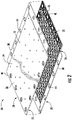
- Figure 2 shows the outer surface 24 of the first layer and the inner surface 32 of the second layer 30.
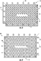
- Figure 3 shows an embodiment the mat 10 from the outer surface 24 of a first layer 20.
- Figure 4 shows the mat 10 from the outer surface 34 of an oppositely disposed second layer 30.
- Each of these layers 20, 30 may be made of the same material as discussed above, preferably HDPE plastic, optionally reinforced with adhesives or other additives to provide the desired strength and flex characteristics.
- Each of the layers 20, 30 may be formed by molding, such as compression molding or injection molding, or an otherwise appropriate technique for forming given the particular material used.
- the modular mat 10 comprises a central core area 12, and a flange 14 extending outward from the central core area 12.
- the central core area 12 comprises the majority of the mat 10 and provides the usable surface of the mat 10, upon which equipment and personnel may travel.
- the central core area 12 is the primary load bearing portion of the mat 10. It may therefore be substantially planar, to facilitate the bearing of load and conveyance of people and equipment thereon.
- the central core area 12 shown in Figure 1 is generally rectangular in shape, however, it may be of any suitable shape, including square or hexagonal, provided that the mats 10 are adapted for overlapping and/or interlocking with adjacent mats 10.
- a flange 14 is formed integrally with, and extends outward, from the central core area 12.
- the flange 14 and central core area 12 are formed of the same material, such as described above for the mats 10, such as, but not limited to, a high-density polyethylene (HDPE) plastic.
- the flange 14 is disposed along at least one edge of the mat 10. With reference to Figure 1 , the flange 14 is disposed along two adjacent edges of the mat 10.
- the flange 14 is configured and positioned to provide an area for an adjacent mat 10 to overlap and join the first mat 10, as will be discussed in greater detail hereinafter.
- the flange 14 portion of the mat 10 is further structured to taper or reduce in height as it extends away from the central core area 12.
- the flange 14 has a sloped incline such that it is thicker where the flange 14 meets the central core area 12 and becomes progressively thinner as the flange 14 extends away from the central core area 12.
- the flange 14 is thinnest at the outer edge of the flange 14.
- the first layer 20 includes a central portion 26 and a first flange portion 28.
- the central portion 26 comprises a majority of the first layer 20, and includes the primary load bearing portion of the first layer 20.
- the central portion 26 is rectangular, although in other embodiments the central portion 26 may be square, triangular, hexagonal, or other shape as would be suitable for a load bearing portion of a mat 10.
- the first flange portion 28 is integrally formed with, and extends outwardly from, at least one edge of the central portion 26, but preferably from two adjacent sides.
- the first flange portion 28 may extend the entire length of a side of the central portion 26, or only a part thereof. In a preferred embodiment, the first flange portion 28 extends along a substantial length of a side of the central portion 26.
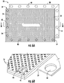
- the second layer 30 similarly has a central portion 36 and second flange portion 38, as seen in Figures 6A and 6C .
- the first and second layers 20, 30 are joined or affixed together to form the mat 10 of the present invention.
- the first and second layers 20, 30 are disposed so that their respective inner surfaces 22, 32 are facing one another. Accordingly, the oppositely disposed outer surfaces 24, 34 face outward, as seen in Figures 9A-10B .
- the first and second layers 20, 30 are positioned relative to each other so that a peripheral part of the central portion 26 of the first layer 20 corresponds to and matches with the facing second flange portion 38 of the second layer 30, and a peripheral part of the central portion 36 of the second layer 30 corresponds to and matches with the facing first flange portion 28 of the first layer 20, as shown in Figure 2 .
- the flange 14 of the mat 10 is therefore a combination of a first or second flange portion 28, 38 from one layer and a part of the central portion 26, 36 of the other layer.
- first and second layers 20, 30 are arranged and joined to form a single mat 10 of the present invention, which overall has a central core area 12 and flange 14, as seen in Figures 1 , 3 and 4 .
- the first and second layers 20, 30 are congruently mated and affixed as described above. Accordingly, the mat 10 is defined by a perimeter 16 that encompasses both the central core area 12 and flange 14.
- the flange 14 is not separate from the mat 10, but rather, is integrally formed within and in part defines the mat 10.
- the perimeter 16 of the mat 10 is congruent throughout its entirety, such that there are no overhangs or offset portions of the mat 10 in which any portion of first and second layers 20, 30 are not matched to corresponding sections of the opposite layer 20, 30.
- the first and second layers 20, 30 are joined by affixing their inner surfaces 22, 32 together.
- the inner surfaces 22, 32 may be affixed by any suitable means of securing the two surfaces together, including, but not limited to, the use of connectors such as bolts or screws, adhesive material such as glue, welding such as hand welding or hot welding, and other methods as are appropriate for the materials comprising the inner surfaces 22, 32. Further, multiple methods of affixing the inner surfaces 22, 32 can be utilized simultaneously.
- the inner surfaces 22, 32 may be both glued and bolted together.
- the inner surfaces 22, 32 are both bolted and welded together.
- some portions of the inner surfaces 22, 32 are bolted together and different portions of the inner surfaces 22, 32 are welded together.
- the central portion of inner surfaces 22, 32 may be bolted together, and the perimeter of the formed mat 10 may be hand welded along the interface of the joined inner surfaces 22, 32 to create a seal around the mat 10.
- the inner surfaces 22, 32 are affixed together with a plurality of bolts (not shown) disposed through fixation holes 11 extending through the mat 10.
- the central portion 26, 36 of each layer include a plurality of fixation holes 11 disposed there through.
- the fixation holes 11 in the central portion 26 of the first layer 20 correspond to fixation holes 11 in the central portion 36 of the second layer 30 when the two layers are paired together.
- the fixation holes 11 are configured to receive a connector, such as a bolt or screw, to join the two layers 20, 30 together.
- the fixation holes 11 are configured to receive bolts, which may be sex bolts comprised of a male and female half, in which each half of the bolt enters from an opposite layer 20, 30 of the mat 10 to secure the layers together.
- the inner surfaces 22, 32 are welded together along at least a portion of the inner surfaces 22, 32, and most preferably along the entire inner surfaces 22, 32.
- Such welding may include hot welding, wherein at least one, but preferably each of the inner surfaces 22, 32 are heated to a temperature sufficient to soften (but not melt) the material comprising the inner surfaces 22, 32.
- the heated, softened inner surfaces 22, 32 are then joined and compressed together, and allowed to cool under compression. Any material extruded at the seam of the joined inner surfaces 22, 32 resulting from compression may be removed, such as by grinding, milling or routing once the surfaces are cooled.
- the inner surfaces 22, 32 of the first and second layers 20, 30 may include reinforcing structure 50 integrally formed therein for structural support.
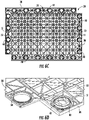
- Figures 5C and 5D show the inner surface 22 of the first layer 20. At least a portion of this inner surface 22 includes a reinforcing structure 50.
- the reinforcing structure 50 comprises a series of intersecting reinforcing ribs 51, creating spaces 52 within the inner surfaces 22, 32 of the layers 20, 30.
- the reinforcing ribs 51 may be disposed in any suitable configuration, such as square, rectangle, triangular, honeycomb and circular patterns, including combinations thereof. The reinforcing ribs 51 are fully integrated into the first layer 20.
- the reinforcing ribs 51 may be constructed or molded from the same material as the first layer 20, as discussed above.
- the reinforcing ribs 51 extend substantially the full thickness of the first layer 20, such that the reinforcing structure 50 has the same height dimension throughout the first layer 20, as seen in the cross-section of the mat 10 in Figure 10A .
- Weight from a load imparted on the outer surface 24 is propagated through the mat 10 by way of the reinforcing ribs 51, which run perpendicular to the outer surface 24.
- the reinforcing ribs 51 therefore provide strength to the mat 10, as well as weight distribution to prevent uneven wear of the mat 10.
- the spaces 52 defined between the reinforcing ribs 51 reduce the amount of material needed for the mat 10.
- the reinforcing structure 50 provides strength and durability to the mat 10 while minimizing the material needed, thus enabling the mat 10 to be easily portable.
- the reinforcing structure 50 covers the entire inner surface 22, including the central portion 26 and the first flange portion 28 of the first layer. In some embodiments, however, the reinforcing structure 50 may only cover the central portion 26, the first flange portion 28, or parts thereof.
- Figures 6C and 6D show the inner surface 32 of the second layer 30. At least a portion of this inner surface 32 includes a reinforcing structure 50 comprising intersecting reinforcing ribs 51 and spaces 52 defined therein.
- the reinforcing structure 50 of the inner surface 32 of the second layer 30 is substantially the same as that described above for the inner surface 22 of the first layer 20.
- the reinforcing structure 50 of the first layer 20 corresponds to and matches the reinforcing structure 50 of the second layer 30, as seen in Figure 10A . Therefore, the interior of the mat 10 is consistent throughout.
- the outer surfaces 24, 34 of the first and second layers 20, 30 are disposed for contacting and engaging the transportation elements, such as walking or vehicular traffic, which may further include heavy loads of equipment, materials, or may simply involve a high degree of traffic. Accordingly, the outer surfaces 24, 34 include a plurality of traction elements 52, 54 to increase the friction on the surface and permit the vehicle and/or pedestrian greater purchase on the surface. The traction elements 52, 54 therefore increase the safety of the mat 10.
- the traction elements 52, 54 generally extend outward from the outer surface 24, 34 of the mat 10 sufficiently to provide additional friction to the surface, but not so far as to be an impediment to motion across the surface.
- the traction elements 52, 54 may also be recesses in the outer surfaces 24, 34 of the mat 10, or a combination of extensions and recesses. They may be disposed in any orientation and configuration along the outer surface 24, 34.
- the mat 10 includes different grades of traction elements 52, 54 for creating different amounts or types of friction, which may be particularly suited for a specific kind of traffic.
- the traction elements 52, 54 are disposed on the central core area 12 of the mat 10, and specifically on the central portion 26, 36 of the composite layers of the mat 10, as these are the load-bearing portions of the mat 10.
- These different grades of traction elements 52, 54 may be located on the same surface of the mat 10, although in a preferred embodiment, each layer of the mat 10 comprises one kind of traction element, and the traction elements of the first layer 20 may be of a different kind than those on the second layer 30.
- the first layer 20 includes a plurality of industrial grade traction elements 52.
- These industrial grade traction elements 52 are raised portions of the outer surface 24, and are of a size and shape appropriate to support the heavy weight loads of industrial applications, such as construction vehicles and equipment, as well as engage large tires or other traction elements during inclement weather or submersion in water or mud.
- the number and distribution of the industrial grade traction elements 52 may vary according to a particular contemplated weight load. Generally, the heavier the weight intended to be supported on the first layer 20, the larger in size and dimension and/or number of the industrial grade traction elements 52 present on the outer surface 24.
- the second surface 30 includes a plurality of pedestrian grade traction elements 54.
- These pedestrian grade traction elements 54 are preferably raised portions of the outer surface 34, and are of a size, shape and configuration to support people walking, running, dancing, or otherwise moving or standing on the outer surface 34 of the mat 10.
- the pedestrian grade traction elements 54 may include raised portions or recesses in the outer surface 34.
- the pedestrian grade traction elements 54 are preferably raised areas of the outer surface 34, but generally do not comprise as high of an elevation as the industrial grade traction elements 52 on the opposing side of the mat 10.
- the pedestrian grade traction elements 54 may include a substantially planar top surface to facilitate easier walking or standing by people, as compared to the industrial grade traction elements 52 of Figure 5B , which need not necessarily have a planar top surface.
- each of the first and second layers 20, 30 further include at least one fitting receiver 40 integrally formed therein.
- the fitting receiver 40 extends through the entire layer first or second layer 20, 30, as shown in Figure 10B , and defines a space in its center.
- the first and second layers 20, 30 include a plurality of fitting receivers 40.
- Each fitting receiver 40 is configured to matingly engage and receive a corresponding pin for attachment purposes, as described in greater detail hereinafter.
- the fitting receiver 40 is shaped as receptacle of a cam lock, which is structured to receive and matingly restrain a cam locking pin. It should be appreciated, however, that the receiver 40 may be of any configuration or shape as is appropriate for securing purposes.
- the fitting receivers 40 preferably are formed along and extend through an attachment edge 27, 37 of each layer 20, 30.
- the attachment edges 27, 37 are sides of the central portions 26, 36 that do not have a flange portion 28, 38 extending therefrom.
- the attachment edges 27, 37 comprise the sides of the central portion 26, 36 opposite the flange portions 28, 38.
- the central core area 12 of the mat 10 includes an attachment edge 18 disposed along at least one edge of the mat 10.
- the central core area 12 includes two attachment edges 18 disposed along adjacent edges of the central core area 12. These attachment edges 18 are disposed on different sides of the central core area 12 from the flange 14.
- the attachment edges 18 are disposed opposite from the flange 14. These attachment edges 18 are structured to overlap the flange 14 of another, adjacent mat 10 when forming the flooring system, as will be discussed in greater detail hereinafter.
- at least one of the attachment edges 27, 37 have a sloped incline which is dimensioned to receive a corresponding flange portion 28, 38 of the opposing layer 20, 30.
- This incline may include a notch 39 or other structure configured to facilitate the fitting of the flange portion 28, 38 of one layer into the sloped incline area of the corresponding attachment edge 27, 37 of the opposing layer. This produces a slope in the resulting flange 14 of the mat 10, to enable overlapping joining of adjacent mats 10.
- the fitting receivers 40 have a receiving end 41 at one end and a locking end 42 at the opposite end.
- the receiving end 40 is structured to receive the corresponding mating locking pin (not shown) for engagement.
- the receiving end 40 is integrally formed in the outer surface 24 of the first layer 20, as in Figure 5B
- the opposite locking end 42 is formed at the inner surface 22 of the first layer, as in Figure 5D .
- the fitting receivers 40 in the second layer 30 are formed such that the receiving ends 42 are formed in the outer surface 34 of the second layer, as in Figure 6B , and the opposing locking ends 42 are formed at the inner surface 32 of the second layer, as in Figure 6D .
- Details of the receiving ends 41 of fitting receivers 40 are shown at Figures 7A and 7B , on respective layers 20, 30 of the mat.
- Details of the locking ends 42 of the fitting receivers 40 are shown in Figures 8A and 8B of respective layers 20, 30 of the mat 10.
- the first and second layers 20, 30 also include at least one, but preferably a plurality of apertures 44 extending through the first and second flange portions 28, 38, respectively.
- the first flange portion 28 of the first layer 20 includes a plurality of apertures 44. These apertures 44 are dimensioned to permit a corresponding fitting receiver 40, and specifically the locking end 42 of a fitting receiver 40, from an opposite layer there through.
- the second flange portion 38 of the second layer 30 also includes a plurality of such apertures 44, as depicted in Figures 6A - 6D .
- the fitting receivers 40 of the central portion 26, 36 of one layer line up with corresponding apertures 44 of the flange portions 28, 38 of the opposing layer, as illustrated in Figure 2 .
- the fitting receivers 40 pass through the corresponding apertures 44, so that when the layers 20, 30 are affixed together in the final configuration, the mat 10 comprises a plurality of fitting receivers 40 disposed through the attachment edges 18 and the flanges 14, as best seen in Figures 3 and 4 .
- the receiving ends 41 of the fitting receivers 40 are present at the core central area 12 of the mat 10, and the locking ends 42 are present along the flange 14 of the mat.
- the present disclosure also contemplates a floor covering system 100 composed of a contiguous placement of the above-described mats 10. Therefore, there are no significant gaps between the modular floor mats 10 to provide essentially complete coverage of the subsurface being covered.
- the floor covering system 100 includes a plurality of mats 10 disposed in adjoining, overlapping and interlocking fashion.
- the system 100 is extendable in multiple directions to accommodate a desired topographic plan.
- Such topographic plan is typically directed towards the conveyance or support of equipment, vehicles, personnel and the like and is adapted to conform to the topographic or geographic features of the substrate surface, such as grass, dirt, artificial turf or the like.
- the mats 10 of the present invention provide distribution of weight over a larger surface area, thus allowing heavy equipment to traverse varying ground conditions.
- the floor covering system 100 further comprises a connection assembly 200, as shown in Figures 12 and 15 .
- the connection assembly 200 includes a fitting receiver 40 integrally formed in a mat 10 and a corresponding locking pin 220 which inserts into and is retained within the fitting receiver 40.
- the floor covering system 100 is built by securing one modular mat 10 to an adjacent modular mat 10, as in Figure 11 .
- Adjacent mats 10 are disposed in at least partially overlapping fashion, such that the attachment edge 18 of one mat 10 overlaps a flange 14 of an adjacent mat.
- the fitting receivers 40 integrally formed in the mats 10 also overlap and correspond one to another, such that the fitting receivers 40 of one mat 10 align with the fitting receivers 40 of the adjacent, underlying mat 10.
- a locking pin 220 is then placed into a receiving end 41 of a fitting receiver 40.
- the locking pin may be a cam locking pin, as shown in the Figures, although it should be appreciated that other locking pins 220 having different configurations may be used as corresponds to and matingly fits within the particular fitting receiver 40 integrally formed in the mats 10.
- the locking pin 220 may be constructed of plastic, such as the same HDPE plastic used in forming the mat 10. In other embodiments, the locking pin 220 may be made of high grade metal, such as aluminum, or other material that is suitable for engaging material of the mat 10.
- the system 100 may include a plurality of connection assemblies 200.
- a plurality of fitting receivers 40 are formed along the edges of the mat 10, and accommodate a plurality of corresponding locking pins 220, thereby providing a number of securing points along the mats 10. This provides stability to the floor covering system 100, restricting the movement of individual mats 10 as a load is moved across multiple mats 10.
- Each of the locking pins 220 includes at least one restraint mechanism, which may include at least one protrusion 240 extending radially from a surface of the locking pin 220.
- the protrusion(s) 240 is configured to securely engage a portion of the fitting receiver 40 in order to lock one overlapping mat 10 to another.
- the locking pin 220 is configured to fit within a receiving end 41 of a fitting receiver 40. In this unlocked position, a number of protrusions 240 on the sides of the locking pin 220 easily fit into corresponding spaces configured in the fitting receiver 40.
- Figure 13B shows the fitting receiver 40 and locking pin 220 in the unlocked position from the opposite side of the mat 10.
- Figure 13C shows a cross-sectional elevation of the fitting receiver 40 and locking pin 220 in an unlocked position.
- the locking pin 220 may be rotated or turned, such as by using a key or tool (not shown), to move the locking pin 220 into a locked position, which is shown in Figure 14A .
- the protrusions 240 now engage restricting structures 46 within the fitting receiver 40 that are configured to restrain further movement of the protrusions 240, thereby locking the pin 220 in place.
- Figure 14B shows the fitting receiver 40 and locking pin 220 in the locked position from the opposite side of the mat 10.
- Figure 14C shows a cross-sectional elevation of the fitting receiver 40 and locking pin 220 in the locked position.
- the locking pin 220 includes a plurality of protrusions 240, at least one of which is a ramp 260 configured to engage a corresponding interior portion of a fitting receiver 40 so as to produce compressive force as the locking pin 220 is turned from an unlocked to a locked position.
- the ramp 260 is formed in the exterior of the locking pin 220 and slopes at an incline radially outward from the locking pin 220.
- the interior of the fitting receiver 40 may have a corresponding slope configured to matingly receive the ramp.
- the ramp 260 engages the corresponding structure of the fitting receiver 40 of the lower, underlying mat 10. Accordingly, as the locking pin 220 turns, the ramp 260 effectively pulls the mats 10 together and compressively secures them tightly together. As a result, the mats 10, once locked, do not move relative to one another.
- the locking pin 220 also comprises a removable blocking wall 280, as shown in Figure 16 .
- the blocking wall 280 is disposed across the inner diameter of the locking pin 220 to prevent the passage of material through the pin 220. Accordingly, debris from the surface of the floor covering system 100 does not enter the locking mechanism, and therefore does not interfere with the interlocking of the mats 10.
- the blocking wall 280 may preferably be recessed from the exterior surface of the pin 220, so that it does not prevent actuation of the pin 220 by a tool or key for locking and unlocking. Additionally, the blocking wall 280 may be removable, such as by puncturing, if desired to permit material such as rainwater to pass through the floor covering system 100.
Landscapes
- Engineering & Computer Science (AREA)
- Architecture (AREA)
- Civil Engineering (AREA)
- Structural Engineering (AREA)
- Physics & Mathematics (AREA)
- Electromagnetism (AREA)
- Floor Finish (AREA)
Applications Claiming Priority (3)
| Application Number | Priority Date | Filing Date | Title |
|---|---|---|---|
| US14/918,061 US9506255B1 (en) | 2015-10-20 | 2015-10-20 | Modular flooring device and system |
| EP16858196.5A EP3365494B1 (fr) | 2015-10-20 | 2016-10-20 | Tapis de sol modulaire |
| PCT/US2016/057856 WO2017070311A1 (fr) | 2015-10-20 | 2016-10-20 | Dispositif et système de revêtement de sol modulaire |
Related Parent Applications (1)
| Application Number | Title | Priority Date | Filing Date |
|---|---|---|---|
| EP16858196.5A Division EP3365494B1 (fr) | 2015-10-20 | 2016-10-20 | Tapis de sol modulaire |
Publications (2)
| Publication Number | Publication Date |
|---|---|
| EP4112840A1 true EP4112840A1 (fr) | 2023-01-04 |
| EP4112840B1 EP4112840B1 (fr) | 2025-10-08 |
Family
ID=57351916
Family Applications (2)
| Application Number | Title | Priority Date | Filing Date |
|---|---|---|---|
| EP16858196.5A Active EP3365494B1 (fr) | 2015-10-20 | 2016-10-20 | Tapis de sol modulaire |
| EP22191194.4A Active EP4112840B1 (fr) | 2015-10-20 | 2016-10-20 | Système de plancher modulaire |
Family Applications Before (1)
| Application Number | Title | Priority Date | Filing Date |
|---|---|---|---|
| EP16858196.5A Active EP3365494B1 (fr) | 2015-10-20 | 2016-10-20 | Tapis de sol modulaire |
Country Status (3)
| Country | Link |
|---|---|
| US (2) | US9506255B1 (fr) |
| EP (2) | EP3365494B1 (fr) |
| WO (1) | WO2017070311A1 (fr) |
Families Citing this family (37)
| Publication number | Priority date | Publication date | Assignee | Title |
|---|---|---|---|---|
| US9637871B2 (en) * | 2014-06-18 | 2017-05-02 | Newpark Mats & Integrated Services Llc | Load-supporting surface with actively connected gap seals and related apparatus and methods |
| US9885156B2 (en) * | 2015-01-09 | 2018-02-06 | M. Casey Malmquist | Pick mat locking system |
| USD928993S1 (en) | 2015-10-20 | 2021-08-24 | Signature Systems Group, Llc | Modular flooring device |
| USD832468S1 (en) * | 2015-10-20 | 2018-10-30 | Signature Systems Group, Llc | Modular flooring device |
| US9506255B1 (en) * | 2015-10-20 | 2016-11-29 | Signature Systems Group, Llc | Modular flooring device and system |
| US11584035B2 (en) * | 2015-12-09 | 2023-02-21 | Phoenix Partners, Llc | Apparatus and system for die press and cutting |
| USD794225S1 (en) * | 2016-01-15 | 2017-08-08 | 670988 Nb Inc. | Modular ground covering panel |
| NL2016344B1 (en) * | 2016-03-01 | 2017-09-11 | Permavoid Ltd | Support structure for a surface area provided with at least one connecting plug. |
| USD821001S1 (en) * | 2016-03-31 | 2018-06-19 | Randolph S Reddick | Interlocking floor panel |
| US20190284818A1 (en) * | 2016-07-21 | 2019-09-19 | Quality Mat Company | Segmented panel mat |
| US10895044B2 (en) * | 2016-07-29 | 2021-01-19 | Quality Mat Company | Lightweight universal panel mat |
| US10662589B2 (en) * | 2017-03-24 | 2020-05-26 | Matrax, Inc. | Industrial support mat interlock device |
| USD850662S1 (en) | 2017-03-31 | 2019-06-04 | 670988 Nb Inc. | Berm containment device |
| RU175907U1 (ru) * | 2017-07-04 | 2017-12-22 | Федеральное государственное казенное военное образовательное учреждение высшего образования "ВОЕННАЯ АКАДЕМИЯ МАТЕРИАЛЬНО-ТЕХНИЧЕСКОГО ОБЕСПЕЧЕНИЯ имени генерала армии А.В. Хрулева" | Легкая плита дорожного покрытия |
| CN111373108B (zh) * | 2017-11-21 | 2022-01-11 | 艾德克有限公司 | 用于在表面覆盖结构中连接面板的夹具及制造方法 |
| US10647228B2 (en) * | 2018-01-31 | 2020-05-12 | Toyota Motor Engineering & Manufacturing North America, Inc. | Protective seat load floor for hybrid vehicles |
| USD900346S1 (en) | 2018-03-15 | 2020-10-27 | Everblock Systems Llc | Flooring module |
| US10196826B1 (en) | 2018-04-16 | 2019-02-05 | EverBlock Systems, LLC | Elevated flooring system |
| US12291826B2 (en) * | 2019-02-28 | 2025-05-06 | Newpark Mats & Integrated Services Llc | Overlapping modular mat system including mat components having fortifying members |
| USD938266S1 (en) | 2019-03-04 | 2021-12-14 | Signature Systems Group, Llc | Connector pin |
| USD895161S1 (en) | 2019-04-12 | 2020-09-01 | Signature Systems Group Llc | Modular flooring tile |
| US10822809B1 (en) * | 2019-07-09 | 2020-11-03 | Joseph Linnane | Modular decking assembly |
| US10842303B1 (en) * | 2019-07-09 | 2020-11-24 | Checkers Industrial Products, Llc | Anti-fatigue mat |
| US11746811B2 (en) * | 2019-09-25 | 2023-09-05 | Signature Systems Group, Llc | Connector pin |
| WO2021081467A1 (fr) * | 2019-10-25 | 2021-04-29 | Spartan Mat, Llc | Système de tapis modulaire |
| RU199481U1 (ru) * | 2020-05-29 | 2020-09-03 | Владимир Владимирович Каретников | Модульное покрытие |
| US12129608B2 (en) * | 2020-06-02 | 2024-10-29 | Newpark Mats & Integrated Services Llc | Overlapping modular mat systems |
| US20220064963A1 (en) | 2020-08-26 | 2022-03-03 | Wearwell, Llc | Integrated mat assembly and method of use |
| US11913179B2 (en) * | 2020-10-05 | 2024-02-27 | Newpark Mats & Integrated Services Llc | Mats and connector systems thereof |
| US20240360681A1 (en) | 2021-05-14 | 2024-10-31 | Interestelar X Spa | High strength modular floor |
| GB2612034A (en) * | 2021-10-19 | 2023-04-26 | Jonathan Ardern Fergus | A panel connection |
| GB2613355B (en) * | 2021-11-30 | 2024-02-28 | Ground Guards Ltd | Fastening device for ground protection mats |
| USD1002034S1 (en) * | 2022-02-08 | 2023-10-17 | Michael Maness | Plate with tread pattern |
| USD1002035S1 (en) * | 2022-02-08 | 2023-10-17 | Michael Maness | Plate with tread pattern |
| ES1300071Y (es) * | 2023-04-04 | 2023-08-23 | Farinha Ibel Agustin Balbis | Panel cobertor para cubrir areas de trabajo |
| US20240351293A1 (en) * | 2023-04-18 | 2024-10-24 | Richard Sofia | Construction mats and methods of manufacture |
| GB2631430A (en) * | 2023-06-29 | 2025-01-08 | Jonathan Ardern Fergus | Apparatus for releasably connecting panels together |
Citations (3)
| Publication number | Priority date | Publication date | Assignee | Title |
|---|---|---|---|---|
| US20030113162A1 (en) * | 2000-05-31 | 2003-06-19 | Seaux Ores Paul | Interlocking mat system for construction of load supporting surfaces |
| US20040005430A1 (en) * | 2002-03-22 | 2004-01-08 | Rogers D. Scott | Interlocking mat |
| US20140137505A1 (en) * | 2012-11-20 | 2014-05-22 | Everest Plastik Inc. | Connector assembly for modular ground covering panels |
Family Cites Families (75)
| Publication number | Priority date | Publication date | Assignee | Title |
|---|---|---|---|---|
| US1977496A (en) | 1931-09-28 | 1934-10-16 | Nat Wood Products Co | Floor expansion joint |
| US3397496A (en) | 1965-02-04 | 1968-08-20 | K & Associates Inc As | Locking means for roof and wall panel construction |
| US3964221A (en) | 1973-08-24 | 1976-06-22 | Aggressive Industries Inc. | Platform sections |
| US4198795A (en) | 1978-05-15 | 1980-04-22 | Barnidge, Inc. | Stainless steel flooring |
| US4238181A (en) | 1978-12-21 | 1980-12-09 | Hooker Chemicals & Plastics Corp. | Method and apparatus for runnerless injection-compression molding thermosetting materials |
| US4436779A (en) | 1982-07-02 | 1984-03-13 | Menconi K Anthony | Modular surface such as for use in sports |
| US4629358A (en) * | 1984-07-17 | 1986-12-16 | The United States Of America As Represented By The Secretary Of The Navy | Prefabricated panels for rapid runway repair and expedient airfield surfacing |
| GB8612355D0 (en) | 1986-05-21 | 1986-06-25 | Aristodimou E | Stone tiles |
| US4988131A (en) | 1988-07-08 | 1991-01-29 | Sico Incorporated | Interlocking sections for portable floors and the like |
| GB9004795D0 (en) | 1990-03-02 | 1990-04-25 | Macleod Iain M | Cover for grassed area |
| DK167379B1 (da) | 1990-12-04 | 1993-10-25 | Lego As | Legetoejsbyggeelement med affjedringsmekanisme |
| DK89291D0 (da) | 1991-05-13 | 1991-05-13 | Frank Bentzon | Gulvbelaegningssystem med sammenkoblige fliseelementer, navnlig plastfliser |
| GB2256023A (en) | 1991-05-18 | 1992-11-25 | Magnet Holdings Ltd | Joint |
| US5403063A (en) | 1993-05-21 | 1995-04-04 | Sjostedt; Robbie J. | Modular integral floor construction for vehicle body |
| US5469999A (en) | 1993-07-29 | 1995-11-28 | Phirippidis; George | Modular storage and organizing system for vehicles |
| US5407342A (en) | 1993-09-13 | 1995-04-18 | Boucher; Paul Y. | Apparatus for manufacturing a composite product |
| US5992106A (en) | 1995-09-21 | 1999-11-30 | Sport Court, Inc. | Hexagon tile with equilateral reinforcement |
| US5653551A (en) * | 1995-10-11 | 1997-08-05 | Seaux; Ores Paul | Mat system for construction of roadways and support surfaces |
| US5833386A (en) | 1995-10-25 | 1998-11-10 | Teletek Industries, Inc. | Modular roll-out portable floor and walkway |
| US5630304A (en) | 1995-12-28 | 1997-05-20 | Austin; John | Adjustable interlock floor tile |
| US6023806A (en) | 1996-09-30 | 2000-02-15 | Martin Marietta Materials, Inc. | Modular polymer matrix composite support structure and methods of constructing same |
| WO1998017357A1 (fr) | 1996-10-18 | 1998-04-30 | Variform Oy | Structure de protection |
| US6063315A (en) | 1997-03-07 | 2000-05-16 | Cascade Engineering, Inc. | Gas-assisted injection molding of large panels with sequential gating |
| US6032428A (en) | 1997-10-27 | 2000-03-07 | Ameritech Plastics Incorporated (A Delaware Corporation) | Modular roll-out portable floor for ice surfaces |
| US6719551B2 (en) | 1997-12-18 | 2004-04-13 | Dale E. Polk, Jr. | Thermoplastic molding process and apparatus |
| US7208219B2 (en) | 1997-12-18 | 2007-04-24 | Lrm Industries, Llc | Thermoplastic molding process and apparatus |
| US6869558B2 (en) | 1997-12-18 | 2005-03-22 | Thermoplastic Composite Designs, Inc. | Thermoplastic molding process and apparatus |
| US6554604B1 (en) | 1998-03-03 | 2003-04-29 | Synventive Molding Solutions Canada, Inc. | System for individual control of multiple valve gates |
| US6098354A (en) | 1998-04-07 | 2000-08-08 | Dante Design Associates, Inc. | Modular floor tile having reinforced interlocking portions |
| AU4220999A (en) | 1998-06-01 | 1999-12-20 | Herman Miller, Inc. | Modular floor tiles and floor system |
| US6282858B1 (en) | 1999-03-04 | 2001-09-04 | Andrew C. Swick | Roofing panel system and method for making same |
| GB9907607D0 (en) | 1999-04-06 | 1999-05-26 | Terraplas Plc | Cover assembly |
| US6220785B1 (en) | 1999-04-28 | 2001-04-24 | Jack Kennedy Metal Products & Buildings, Inc. | Mine stopping, method of constructing same and panels thereof |
| US7393199B2 (en) | 2000-04-06 | 2008-07-01 | Mgs Mfg. Group, Inc. | Multi-shot injection molding arrangement |
| US6649110B1 (en) | 2000-05-31 | 2003-11-18 | Ols Consulting Services, Inc. | Method for manufacturing molded panels |
| EP1199424A1 (fr) | 2000-10-12 | 2002-04-24 | Schlüter-Systems KG | Construction d'un pont pour des joints de dilatation dans des murs ou des planchers des bâtiments |
| AU2002235156A1 (en) | 2000-11-06 | 2002-05-15 | Frederick J. Buja | Method and apparatus for controlling a mold melt-flow process using temperature sensors |
| US6564522B1 (en) | 2001-11-20 | 2003-05-20 | Lee Chiu-Ying | Hidden dual loading spring-type floor board fastening mount structure |
| AUPR998002A0 (en) | 2002-01-17 | 2002-02-07 | Design Develop Commercialise Pty Ltd | Modular plastic flooring |
| US7004736B2 (en) | 2002-04-18 | 2006-02-28 | Talmolder Inc. | Method and apparatus for producing molded articles |
| DE20209502U1 (de) | 2002-06-19 | 2002-08-29 | BERDING BETON GmbH, 49439 Steinfeld | Viereckiges Bodenbelagelement und Form zur Herstellung desselben |
| US6685388B2 (en) * | 2002-08-05 | 2004-02-03 | The United States Of America As Represented By The Secretary Of The Army | Multi-purpose mat |
| US6909373B2 (en) | 2003-05-09 | 2005-06-21 | Vitrak Wireless Inc. | Floor monitoring system |
| US8397466B2 (en) | 2004-10-06 | 2013-03-19 | Connor Sport Court International, Llc | Tile with multiple-level surface |
| US20060265975A1 (en) | 2005-05-04 | 2006-11-30 | Kurt Geffe | Floor tile |
| WO2007016978A1 (fr) | 2005-08-08 | 2007-02-15 | Kronospan Technical Company Ltd. | Profile de dilatation affleurant |
| US7717697B2 (en) | 2005-08-30 | 2010-05-18 | Sharon Hutchinson | Methods and systems for controlling mold temperatures |
| CA2520434C (fr) | 2005-09-20 | 2013-01-08 | Covermaster Inc. | Couverture protectrice de surface polyvalente |
| US20070102243A1 (en) * | 2005-11-08 | 2007-05-10 | Daniel Ruminski | Modular heated platform |
| US7621091B2 (en) | 2005-11-10 | 2009-11-24 | Sico Incorporated | Portable floor |
| DE202005020074U1 (de) | 2005-12-21 | 2006-04-20 | Herm. Friedr. Künne Gmbh & Co. | Profilschienensystem |
| GB2433539A (en) | 2005-12-23 | 2007-06-27 | Woodpath Ventures Ltd | Mat for use in temporary road, scaffolding and the like |
| DE102006006124A1 (de) | 2006-02-10 | 2007-08-23 | Flooring Technologies Ltd. | Einrichtung zum Verriegeln zweier Bauplatten |
| US7571573B2 (en) | 2006-04-11 | 2009-08-11 | Moller Jr Jorgen J | Modular floor tile with lower cross rib |
| US7914228B2 (en) | 2006-05-17 | 2011-03-29 | Antonio Rapaz | Multi-purpose construction module |
| US7413374B2 (en) * | 2006-06-01 | 2008-08-19 | Rogers D Scott | Overlapping secured mat system |
| US20080127593A1 (en) | 2006-07-14 | 2008-06-05 | Janesky Lawrence M | Moisture-resistant cover floor system for concrete floors |
| US7837917B2 (en) | 2006-08-30 | 2010-11-23 | Lrm Industries International, Inc. | Method of forming a molded plastic article having molded extensions |
| US7779595B2 (en) | 2006-10-25 | 2010-08-24 | Lrm Industries International, Inc. | Molded panel and panel assembly |
| US7955550B2 (en) | 2007-04-20 | 2011-06-07 | Lrm Industries International, Inc | Method of preparing a molded article |
| US7842225B2 (en) | 2007-04-20 | 2010-11-30 | Lrm Industries International, Inc. | Method of preparing a molded article |
| US8464490B2 (en) * | 2007-05-09 | 2013-06-18 | Antonio Rapaz | Construction panel |
| US7931845B2 (en) | 2007-05-21 | 2011-04-26 | O & D Manufacturing | Gravity injection of molding material for compression molding and related methods |
| US7842226B2 (en) | 2007-09-07 | 2010-11-30 | Lrm Industries International, Inc. | Method of preparing a molded article |
| US8535582B2 (en) | 2008-10-23 | 2013-09-17 | Lrm Industries International, Inc. | Method of forming a molded article by wireless control |
| CA2750802A1 (fr) | 2009-01-30 | 2010-08-05 | Lrm Industries International, Inc. | Procede de formation d'un article moule a partir de feuilles thermoplastiques faconnables thermiquement |
| US20110097489A1 (en) | 2009-10-27 | 2011-04-28 | Kerr Roger S | Distribution manifold including multiple fluid communication ports |
| US8414217B2 (en) * | 2011-04-20 | 2013-04-09 | Signature Fencing And Flooring Systems, Llc | Heavy duty modular flooring and roadway device |
| US8936374B1 (en) * | 2012-01-10 | 2015-01-20 | John P. Royse | Turf protection system and LED flooring system for preserving natural turf |
| US9212746B2 (en) * | 2012-04-09 | 2015-12-15 | Newpark Mats & Integrated Services Llc | Apparatus and methods for sealing between adjacent components of a load-supporting surface |
| US8973328B2 (en) * | 2013-07-12 | 2015-03-10 | Macneil Ip Llc | Floor tile expansion joint |
| US9337586B2 (en) * | 2013-10-09 | 2016-05-10 | Newpark Mats & Integrated Sevices, LLC | Apparatus and methods for electrically grounding a load-supporting surface |
| US9637871B2 (en) * | 2014-06-18 | 2017-05-02 | Newpark Mats & Integrated Services Llc | Load-supporting surface with actively connected gap seals and related apparatus and methods |
| US9506255B1 (en) * | 2015-10-20 | 2016-11-29 | Signature Systems Group, Llc | Modular flooring device and system |
| US10895044B2 (en) | 2016-07-29 | 2021-01-19 | Quality Mat Company | Lightweight universal panel mat |
-
2015
- 2015-10-20 US US14/918,061 patent/US9506255B1/en not_active Expired - Fee Related
-
2016
- 2016-10-07 US US15/288,039 patent/US20170107725A1/en not_active Abandoned
- 2016-10-20 EP EP16858196.5A patent/EP3365494B1/fr active Active
- 2016-10-20 EP EP22191194.4A patent/EP4112840B1/fr active Active
- 2016-10-20 WO PCT/US2016/057856 patent/WO2017070311A1/fr not_active Ceased
Patent Citations (3)
| Publication number | Priority date | Publication date | Assignee | Title |
|---|---|---|---|---|
| US20030113162A1 (en) * | 2000-05-31 | 2003-06-19 | Seaux Ores Paul | Interlocking mat system for construction of load supporting surfaces |
| US20040005430A1 (en) * | 2002-03-22 | 2004-01-08 | Rogers D. Scott | Interlocking mat |
| US20140137505A1 (en) * | 2012-11-20 | 2014-05-22 | Everest Plastik Inc. | Connector assembly for modular ground covering panels |
Also Published As
| Publication number | Publication date |
|---|---|
| EP3365494A1 (fr) | 2018-08-29 |
| US9506255B1 (en) | 2016-11-29 |
| EP3365494A4 (fr) | 2019-06-19 |
| EP4112840B1 (fr) | 2025-10-08 |
| EP3365494B1 (fr) | 2022-09-14 |
| WO2017070311A1 (fr) | 2017-04-27 |
| US20170107725A1 (en) | 2017-04-20 |
Similar Documents
| Publication | Publication Date | Title |
|---|---|---|
| US9506255B1 (en) | Modular flooring device and system | |
| US8414217B2 (en) | Heavy duty modular flooring and roadway device | |
| US10895044B2 (en) | Lightweight universal panel mat | |
| US10626621B2 (en) | Method and apparatus for construction mats | |
| US20190119862A1 (en) | Lightweight panel mat assemblies with adapters and side ramps | |
| US9051739B2 (en) | Modular flooring system | |
| US20180030666A1 (en) | Lightweight panel mat with interlocking elements | |
| CA3029289C (fr) | Dalles modulaires et systeme de dalles modulaires | |
| US7303800B2 (en) | Interlocking mat | |
| US9670624B1 (en) | Double walled earth grabbing water permeable modular paver | |
| CA2593600C (fr) | Panneaux polyvalents avec rive modulaire | |
| US20190284818A1 (en) | Segmented panel mat | |
| US7025530B2 (en) | Road mats | |
| GB2433539A (en) | Mat for use in temporary road, scaffolding and the like | |
| EP3931397A1 (fr) | Système de tapis modulaire à chevauchement comprenant des composants de tapis ayant des éléments de renforcement | |
| US12618201B2 (en) | Modular mat system | |
| US20250019974A1 (en) | Versatile Modular Flooring Device and System | |
| US20220372712A1 (en) | Modular Mat System | |
| US20130078041A1 (en) | Load-Bearing Mat | |
| CA2871374A1 (fr) | Tapis de confinement secondaire |
Legal Events
| Date | Code | Title | Description |
|---|---|---|---|
| PUAI | Public reference made under article 153(3) epc to a published international application that has entered the european phase |
Free format text: ORIGINAL CODE: 0009012 |
|
| STAA | Information on the status of an ep patent application or granted ep patent |
Free format text: STATUS: THE APPLICATION HAS BEEN PUBLISHED |
|
| AC | Divisional application: reference to earlier application |
Ref document number: 3365494 Country of ref document: EP Kind code of ref document: P |
|
| AK | Designated contracting states |
Kind code of ref document: A1 Designated state(s): AL AT BE BG CH CY CZ DE DK EE ES FI FR GB GR HR HU IE IS IT LI LT LU LV MC MK MT NL NO PL PT RO RS SE SI SK SM TR |
|
| STAA | Information on the status of an ep patent application or granted ep patent |
Free format text: STATUS: REQUEST FOR EXAMINATION WAS MADE |
|
| 17P | Request for examination filed |
Effective date: 20230623 |
|
| RBV | Designated contracting states (corrected) |
Designated state(s): AL AT BE BG CH CY CZ DE DK EE ES FI FR GB GR HR HU IE IS IT LI LT LU LV MC MK MT NL NO PL PT RO RS SE SI SK SM TR |
|
| GRAP | Despatch of communication of intention to grant a patent |
Free format text: ORIGINAL CODE: EPIDOSNIGR1 |
|
| STAA | Information on the status of an ep patent application or granted ep patent |
Free format text: STATUS: GRANT OF PATENT IS INTENDED |
|
| INTG | Intention to grant announced |
Effective date: 20241128 |
|
| RIN1 | Information on inventor provided before grant (corrected) |
Inventor name: BERGHUIS, BART Inventor name: HIMES, DANIEL Inventor name: WOLFF, ANDREW Inventor name: SNEERINGER, ANDREW Inventor name: JONES, CHAD H. |
|
| GRAJ | Information related to disapproval of communication of intention to grant by the applicant or resumption of examination proceedings by the epo deleted |
Free format text: ORIGINAL CODE: EPIDOSDIGR1 |
|
| STAA | Information on the status of an ep patent application or granted ep patent |
Free format text: STATUS: REQUEST FOR EXAMINATION WAS MADE |
|
| GRAP | Despatch of communication of intention to grant a patent |
Free format text: ORIGINAL CODE: EPIDOSNIGR1 |
|
| INTC | Intention to grant announced (deleted) | ||
| STAA | Information on the status of an ep patent application or granted ep patent |
Free format text: STATUS: GRANT OF PATENT IS INTENDED |
|
| INTG | Intention to grant announced |
Effective date: 20250430 |
|
| GRAS | Grant fee paid |
Free format text: ORIGINAL CODE: EPIDOSNIGR3 |
|
| GRAA | (expected) grant |
Free format text: ORIGINAL CODE: 0009210 |
|
| STAA | Information on the status of an ep patent application or granted ep patent |
Free format text: STATUS: THE PATENT HAS BEEN GRANTED |
|
| AC | Divisional application: reference to earlier application |
Ref document number: 3365494 Country of ref document: EP Kind code of ref document: P |
|
| AK | Designated contracting states |
Kind code of ref document: B1 Designated state(s): AL AT BE BG CH CY CZ DE DK EE ES FI FR GB GR HR HU IE IS IT LI LT LU LV MC MK MT NL NO PL PT RO RS SE SI SK SM TR |
|
| REG | Reference to a national code |
Ref country code: GB Ref legal event code: FG4D Ref country code: CH Ref legal event code: F10 Free format text: ST27 STATUS EVENT CODE: U-0-0-F10-F00 (AS PROVIDED BY THE NATIONAL OFFICE) Effective date: 20251008 |
|
| REG | Reference to a national code |
Ref country code: DE Ref legal event code: R096 Ref document number: 602016093785 Country of ref document: DE |
|
| REG | Reference to a national code |
Ref country code: IE Ref legal event code: FG4D |
|
| REG | Reference to a national code |
Ref country code: CH Ref legal event code: U11 Free format text: ST27 STATUS EVENT CODE: U-0-0-U10-U11 (AS PROVIDED BY THE NATIONAL OFFICE) Effective date: 20251118 |
|
| REG | Reference to a national code |
Ref country code: CH Ref legal event code: R17 Free format text: ST27 STATUS EVENT CODE: U-0-0-R10-R17 (AS PROVIDED BY THE NATIONAL OFFICE) Effective date: 20251219 |
|
| PGFP | Annual fee paid to national office [announced via postgrant information from national office to epo] |
Ref country code: DE Payment date: 20251126 Year of fee payment: 10 |
|
| PGFP | Annual fee paid to national office [announced via postgrant information from national office to epo] |
Ref country code: GB Payment date: 20251125 Year of fee payment: 10 |
|
| PGFP | Annual fee paid to national office [announced via postgrant information from national office to epo] |
Ref country code: FR Payment date: 20251126 Year of fee payment: 10 |
|
| PGFP | Annual fee paid to national office [announced via postgrant information from national office to epo] |
Ref country code: CH Payment date: 20251118 Year of fee payment: 10 |
|
| REG | Reference to a national code |
Ref country code: NL Ref legal event code: MP Effective date: 20251008 |
|
| REG | Reference to a national code |
Ref country code: AT Ref legal event code: MK05 Ref document number: 1844897 Country of ref document: AT Kind code of ref document: T Effective date: 20251008 |
|
| PG25 | Lapsed in a contracting state [announced via postgrant information from national office to epo] |
Ref country code: NL Free format text: LAPSE BECAUSE OF FAILURE TO SUBMIT A TRANSLATION OF THE DESCRIPTION OR TO PAY THE FEE WITHIN THE PRESCRIBED TIME-LIMIT Effective date: 20251008 |
|
| PG25 | Lapsed in a contracting state [announced via postgrant information from national office to epo] |
Ref country code: ES Free format text: LAPSE BECAUSE OF FAILURE TO SUBMIT A TRANSLATION OF THE DESCRIPTION OR TO PAY THE FEE WITHIN THE PRESCRIBED TIME-LIMIT Effective date: 20251008 |
|
| REG | Reference to a national code |
Ref country code: LT Ref legal event code: MG9D |
|
| PG25 | Lapsed in a contracting state [announced via postgrant information from national office to epo] |
Ref country code: NO Free format text: LAPSE BECAUSE OF FAILURE TO SUBMIT A TRANSLATION OF THE DESCRIPTION OR TO PAY THE FEE WITHIN THE PRESCRIBED TIME-LIMIT Effective date: 20260108 |
|
| PG25 | Lapsed in a contracting state [announced via postgrant information from national office to epo] |
Ref country code: AT Free format text: LAPSE BECAUSE OF FAILURE TO SUBMIT A TRANSLATION OF THE DESCRIPTION OR TO PAY THE FEE WITHIN THE PRESCRIBED TIME-LIMIT Effective date: 20251008 Ref country code: HR Free format text: LAPSE BECAUSE OF FAILURE TO SUBMIT A TRANSLATION OF THE DESCRIPTION OR TO PAY THE FEE WITHIN THE PRESCRIBED TIME-LIMIT Effective date: 20251008 Ref country code: FI Free format text: LAPSE BECAUSE OF FAILURE TO SUBMIT A TRANSLATION OF THE DESCRIPTION OR TO PAY THE FEE WITHIN THE PRESCRIBED TIME-LIMIT Effective date: 20251008 |
|
| PG25 | Lapsed in a contracting state [announced via postgrant information from national office to epo] |
Ref country code: RS Free format text: LAPSE BECAUSE OF FAILURE TO SUBMIT A TRANSLATION OF THE DESCRIPTION OR TO PAY THE FEE WITHIN THE PRESCRIBED TIME-LIMIT Effective date: 20260108 |
|
| PG25 | Lapsed in a contracting state [announced via postgrant information from national office to epo] |
Ref country code: IS Free format text: LAPSE BECAUSE OF FAILURE TO SUBMIT A TRANSLATION OF THE DESCRIPTION OR TO PAY THE FEE WITHIN THE PRESCRIBED TIME-LIMIT Effective date: 20260208 |
|
| PG25 | Lapsed in a contracting state [announced via postgrant information from national office to epo] |
Ref country code: PT Free format text: LAPSE BECAUSE OF FAILURE TO SUBMIT A TRANSLATION OF THE DESCRIPTION OR TO PAY THE FEE WITHIN THE PRESCRIBED TIME-LIMIT Effective date: 20260209 |
|
| PG25 | Lapsed in a contracting state [announced via postgrant information from national office to epo] |
Ref country code: PL Free format text: LAPSE BECAUSE OF FAILURE TO SUBMIT A TRANSLATION OF THE DESCRIPTION OR TO PAY THE FEE WITHIN THE PRESCRIBED TIME-LIMIT Effective date: 20251008 |
|
| PG25 | Lapsed in a contracting state [announced via postgrant information from national office to epo] |
Ref country code: LV Free format text: LAPSE BECAUSE OF FAILURE TO SUBMIT A TRANSLATION OF THE DESCRIPTION OR TO PAY THE FEE WITHIN THE PRESCRIBED TIME-LIMIT Effective date: 20251008 |