EP4112850B1 - Palier de poignée et ensemble de poignée de porte ou de fenêtre - Google Patents
Palier de poignée et ensemble de poignée de porte ou de fenêtre Download PDFInfo
- Publication number
- EP4112850B1 EP4112850B1 EP22168114.1A EP22168114A EP4112850B1 EP 4112850 B1 EP4112850 B1 EP 4112850B1 EP 22168114 A EP22168114 A EP 22168114A EP 4112850 B1 EP4112850 B1 EP 4112850B1
- Authority
- EP
- European Patent Office
- Prior art keywords
- rosette
- door
- locking
- handle
- window
- Prior art date
- Legal status (The legal status is an assumption and is not a legal conclusion. Google has not performed a legal analysis and makes no representation as to the accuracy of the status listed.)
- Active
Links
Images




Classifications
-
- E—FIXED CONSTRUCTIONS
- E05—LOCKS; KEYS; WINDOW OR DOOR FITTINGS; SAFES
- E05B—LOCKS; ACCESSORIES THEREFOR; HANDCUFFS
- E05B13/00—Devices preventing the key or the handle or both from being used
- E05B13/002—Devices preventing the key or the handle or both from being used locking the handle
- E05B13/004—Devices preventing the key or the handle or both from being used locking the handle by locking the spindle, follower, or the like
-
- E—FIXED CONSTRUCTIONS
- E05—LOCKS; KEYS; WINDOW OR DOOR FITTINGS; SAFES
- E05B—LOCKS; ACCESSORIES THEREFOR; HANDCUFFS
- E05B15/00—Other details of locks; Parts for engagement by bolts of fastening devices
- E05B15/02—Striking-plates; Keepers; Bolt staples; Escutcheons
Definitions
- the present invention relates to a handle bearing for a door or window handle detachably attached thereto according to the preamble of claim 1.
- the invention further relates to a door or window handle set, consisting of a door or window handle and a handle bearing detachably attached to the door or window handle according to the preamble of claim 9.
- a generic handle bearing as well as a door or window handle set, consisting of such a handle bearing and a door or window handle that can be attached to it, are known, for example, from the DE 20 2018 101 588 U1 known.
- the door or window handle has a handle part and a handle neck with a bearing opening on the front to accommodate a profile pin or an adapter for the handle bearing.
- the adapter is attached to the door or window handle in a rotationally fixed manner and is used to transfer a torque when the door or window handle is operated to a door or window gear in order to open or close the window or door.
- the door or window handle itself with a lock, which is preferably located in the area of the handle neck of the door or window handle and which blocks the door or window handle from being turned.
- the object of the present invention is to provide a handle bearing for a door or window handle which is detachably attached to the latter and which is able to prevent the door or window handle from being operated without installing a lock or the like.
- a door or window handle set consisting of a door or window handle and a handle bearing detachably attached to the door or window handle, having the features of claim 8.
- the handle bearing according to the invention has a rosette that can be attached to a door or window.
- the handle bearing also has an adapter that can be attached to the door or window handle in a rotationally fixed manner, which is used to transmit torque to a door or window gear and which is mounted so that it can rotate relative to the rosette.
- the adapter of the handle bearing has a surface that is accommodated in a bearing sleeve of the rosette.
- a locking slide with a locking bolt is slidably mounted on the rosette.
- the outer surface of the adapter has at least one locking pin receptacle.
- the locking slide can be moved between a locking position in which the locking pin protrudes through a locking pin recess in the bearing sleeve of the rosette into the locking pin receptacle, and a release position in which the locking pin does not protrude into the locking pin receptacle in the outer surface of the adapter.
- the locking slide can be locked in the locking position and the release position.
- the locking slide has a coupling element for releasably coupling an actuating element, with which the locking slide can be moved from the locking position to the release position.
- the coupling element can be coupled to the actuating element via a threaded connection, or forms a bayonet lock with the actuating element.
- the coupling element can be coupled to the actuating element via a threaded connection or in the manner of a bayonet lock. Such a connection enables a reliable coupling of the components.
- the locking slide is preferably held in the locking position by at least one spring element in a spring-loaded manner, wherein the at least one spring element is supported on a support web of the rosette.
- the rosette (covered by a cover rosette all the way around and towards the handle part, whereby the cover rosette has a recess through which the actuating element can be at least partially inserted.
- an edge surrounding the recess forms a support surface for supporting the actuating element during a rotary actuation of the actuating element causing a displacement of the locking slide.
- the actuating element has a handle and a coupling piece which is received in the handle in a rotationally fixed manner and can be coupled to the coupling element of the locking slide.
- the coupling piece and the actuating element are preferably designed as hollow cylinders in which a pressure piece and a spring element spring-loading the pressure piece are accommodated.
- At least two pins are arranged on the surface of the cover plate facing the rosette, which pins protrude into corresponding pin receptacles of the rosette.
- the locking slide has at least one guide groove into which a guide web of the rosette is received for guiding the sliding movement of the locking slide relative to the rosette.
- the interaction of the guide groove of the locking slide and the guide bar of the rosette enables easy guidance of the sliding movement of the locking slide relative to the rosette.
- the door or window handle set according to the invention consisting of a door or window handle and a handle bearing detachably attached to the door or window handle, in which the door or window handle has a handle part and a handle neck with a bearing opening for receiving a part of an adapter of the handle bearing, is characterized by a handle bearing as described above.
- a neck piece of the adapter protrudes into the bearing opening of the door or window handle, wherein a hole is provided in a peripheral surface of the neck piece for receiving a fixing screw screwed into a peripheral surface of the handle neck for axially fixing the adapter to the door or window handle.
- a rotary actuation of the door or window handle can be blocked by the locking slide exclusively in a predetermined rotary position of the door or window handle relative to the adapter.
- top, bottom, left, right, front, back, etc. refer exclusively to the exemplary representation and position of the handle bearing, door or window handle, rosette, adapter, locking slide, cover plate and etc. These terms are not to be understood as restrictive, ie these relationships can change due to different working positions or the mirror-symmetrical design or the like.
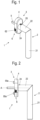
- the reference number 1 designates a first embodiment of a door or window handle set not according to the invention.
- the door or window handle set 1 consists of a door or window handle 2 and a handle bearing 3 detachably attached to the door or window handle 2.
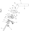
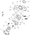
- FIGS. 5 and 6 show an exploded view of the door or window handle set 1 to show in particular the individual components of the handle bearing 3.
- the door or window handle 2 has a handle part 21 and a handle neck 22 aligned at an angle, in particular at a right angle thereto.
- a bearing opening 23 is provided for receiving a neck piece 72 of an adapter 7.
- the adapter 7 serves itself or, as shown in the embodiment variant shown here, via a profile pin 9 received in a profile pin holder 71 of the adapter 7, for the actuation of a door or window gear which is arranged remotely from the handle bearing 3 in the door or window leaf.
- the handle bearing 3 has a rosette 5 which can be fastened to a door or a window, as well as the adapter 7 which can be fastened to the door or window handle 2 in a rotationally fixed manner and which is rotatably mounted relative to the rosette 5.
- the adapter 7 has a jacket surface 74 which is accommodated in a bearing sleeve 53 of the rosette 5.
- the bearing sleeve 53 of the rosette 5 and the jacket surface 74 of the adapter 7 are cylindrical in the embodiment shown here.
- the rosette 5 is designed as an inner rosette, which is partially covered by a cover rosette 4.
- the cover rosette 4 has a base surface 41 facing the door or window handle 2, which has a recess 44 through which the neck piece 72 of the adapter 7 projects into the bearing opening 23 in the handle neck 22 of the door or window handle 2.
- a first casing piece 42 which forms an upper casing piece in a preferred orientation attached to the door or window, encloses a part of the casing surface of a base body 51 of the rosette 5.
- a second casing piece 43 adjoining the first casing piece 42 which preferably forms a lower casing piece in the orientation of the rosette 5 mentioned above, covers a lower casing surface of the base body 51 of the rosette 5 close to the door or window handle 2, wherein the width of the casing surfaces in this lower region of the base body 51 is smaller than the width of the casing surface of the base body 51 in the region of the cover rosette 4 covered by the first casing piece 42.
- a locking slide 6 which is slidably mounted on the rosette 5 is arranged on this lower region of the base body 51 of the rosette 5.
- the locking slide 6 has a locking pin 63.
- the outer surface 74 of the adapter 7 has at least one locking pin receptacle 76, as shown in Figure 6 is shown.
- only one such locking pin receptacle 76 is provided, so that the door or window handle 2 can only be locked by the locking slide 6 in a single predetermined rotational position of the door or window handle 2 relative to the adapter 7.
- the locking slide 6 can preferably be locked in both the locking position and the release position relative to the rosette 5.
- the rosette 5 For fixing to the door or window, the rosette 5 has two through holes 52 which serve to pass through screws with which the rosette 5 can be screwed to the door or window.
- the through openings 52 are formed by receiving sleeves 55.
- the receiving sleeves 55 are extended on the back of the rosette 5 facing the door or window by dowel-like positioning pieces that can be inserted into holes provided for this purpose in the door or window and thus enable pre-positioning of the rosette 5 on the door or window before inserting the screws.
- the locking slide 6 has a through opening 65 which is designed as an elongated hole in order to enable the displacement of the locking slide 6 relative to the rosette 5 and at the same time to hold the locking slide 6 captively on the rosette 5 by receiving one of the receiving sleeves 55 in the through opening 65 of the locking slide 6.
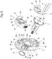
- the locking pin 63 is preferably formed centrally above (viewed in the direction of a sliding movement of the locking slide 6 in the direction of the locking position) on the base body 61 of the locking slide 6 and in the release position is up to the Figure 8 shown locking pin recess 53a of the bearing sleeve 53 of the rosette 5.
- a cover plate 8 is arranged on the rosette 5, which covers the locking slide 6 at least partially (shown in the Figures 5 to 9 ).
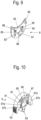
- FIG. 9 A detailed view of the side of the cover plate 8 facing the locking slide 6 is shown in Figure 9 shown as an enlarged detail.
- the contact surfaces 67 each have a first locking groove 67a into which the spring tongues 84 of the cover plate 8 protrude for locking the locking slide 6 in the release position, and a second locking groove 67b into which the spring tongues 84 protrude for locking the locking slide 6 in the locking position.
- the spring tongue 84 is preferably cut out of the material of the base plate 81 of the cover plate 8 on three sides.
- the spring tongues 84 have a curvature 87 in the region of their free ends, which can penetrate into correspondingly deep locking grooves 67a, 67b in the contact surfaces 67 of the locking slide 6.
- the cover plate 8 is as shown in the Figures 7 and 8th can be seen, is fixed in corresponding pin receptacles 56 of the rosette 5 in the direction of the plane of the base plate 81 of the cover plate 8 via three pins 86 protruding from the surface of the cover plate 8 facing the rosette 5.
- the locking slide 6 has, as shown in the Figures 7 and 8th can be clearly seen, two Guide grooves 64 into which a respective guide web 54 of the rosette 5 is received for guiding the sliding movement of the locking slide 6 relative to the rosette 5.
- opposing outer surfaces of the locking slide 6 are provided with a corrugation 62.
- the horizontally extending corrugation 62 shown here is only an example. Other configurations of the corrugation 62 are also conceivable.
- the adapter 7 is provided with a Figures 5 to 8 As shown, a locking ring 75 with several locking receptacles 77 for receiving locking balls 12 is arranged.
- the locking ring 75 is formed on the adapter 7 on an end of the casing surface 74 facing away from a neck piece 72.
- the locking balls 12 can be pressed into the locking receptacles 77 by compression springs 11 accommodated in spring receptacles 59 of the rosette.
- the locking balls 12 are pressed out of the locking receptacles 77 of the locking ring 75 after a predetermined minimum torque has been reached, against the force of the compression springs 11 and, after reaching a next predetermined locking position in the direction of rotation, are pressed back into adjacent locking receptacles 77 by the force of the compression springs 11.
- the locking receptacles 77 are preferably arranged offset by 90° from one another. Furthermore, two such locking balls 12 are preferably provided, which are accommodated in the respective locking receptacles 77 of the locking ring 75 offset by 180° from one another.
- a ring receptacle 78 is formed between a neck piece 72 and the outer surface 74 of the adapter 7, in which a locking ring 10 is inserted for axially fixing the adapter 7 in the rosette 5.
- the locking ring 10 rests on the one hand on a contact surface of the rosette 5 facing the door or window handle 2.
- the radially extending locking ring 75 rests on counter surfaces of the base body 51 of the rosette 5.
- the axial fixation of the door or window handle 2 to the handle bearing 3 is preferably carried out by a fixing screw 24, which is screwed into a threaded bore 25 in a circumferential surface of the handle neck 22 and protrudes into a hole 73 in the neck piece 72 of the adapter 7 (in the assembled state of the door or window handle 2).
- grooves 57 are preferably provided which extend in the direction of the axis of rotation A and corresponding locking elements 45 which protrude from an inner surface of the first shell piece 42 of the cover rosette 4, for example in the form of protruding lugs, which slide along the grooves 57 and thus hold the cover rosette 4 preferably in a frictional manner on the rosette 5.
- locking recesses 58 are provided in the grooves 57, into which the locking elements 45 in the first casing piece 42 of the cover rosette 4 can engage as soon as they have reached the intended end position.
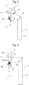
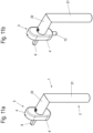
- the locking slide 6' cannot be moved directly manually, but with the aid of an actuating element 13 which can be coupled to the locking slide 6'.
- the locking slide 6' itself is preferably covered by the cover rosette 4' and is therefore not accessible to the user without the aid of the actuating element 13.
- the actuating element 13 is coupled to the locking slide 6' to unlock the door or window handle 2, as shown in Figure 11b ) is shown. As long as the door or window handle 2 is to remain locked by the locking slide 6', the actuating element 13 can be disconnected, as shown in Figure 11a ) is shown.
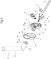
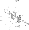
- the latter has a Figure 15 illustrated coupling element 62 for the releasable coupling of the actuating element 13, with which the locking slide 6' can be moved from the locking position into the release position.
- the coupling element 62 and the actuating element 13 together preferably form a bayonet lock.
- the coupling element 62' is preferably formed from a pin protruding from an end face of the locking slide facing away from the locking bolt 63'.
- the pin can have a projection protruding from its outer surface. It is also conceivable to design the pin as a threaded pin with an external thread.
- the actuating element 13, as shown in the Figures 17 and 18 is shown, preferably a handle 131 and a rotationally fixed in the handle 131 received coupling piece 132 which can be coupled to the coupling element 62 of the locking slide 6'.
- the coupling piece 132 is designed to match the shape of the coupling element 62'.
- the coupling piece 132 accordingly has two opposing straight inner grooves extending in the direction of its longitudinal axis, along which the T-shaped projection reaches a widened region of the coupling piece 132 and the coupling element 62 is held in an axially positive manner by subsequent rotation of the actuating element 13.
- the locking slide 6' can then be pulled out of the locking position into the release position by exerting a pulling force in the longitudinal direction of the actuating element 13.
- the coupling element 62 is pulled out using the actuating element 13, the door or window handle 2 can then be pivoted.
- the coupling piece 132 has a correspondingly spiral inner groove, so that by rotating the actuating element 13 the locking slide 6' is pulled out of the locking position into the release position.
- the coupling piece 132 and the actuating element 13 are preferably designed as hollow cylinders in which a pressure piece 133 and a spring element 134 that spring-loads the pressure piece 133 are accommodated.
- the spring-loaded pressure piece 133 prevents the actuating element 13 from being accidentally twisted.
- the locking slide 6' In order to hold the locking slide 6' in its locking position without external actuation by the actuating element, the locking slide 6' is held in the locking position by at least one spring element 14, wherein the at least one spring element 14 is supported on a support web 58' of the rosette 5, as can be seen from the Figures 15 and 16 is evident.
- the rosette 5' is, as in the Figures 12 and 13 shown, covered by a cover rosette 4' circumferentially and towards the handle part 2.
- the cover rosette 4' has a recess 46' in a lower region of the second casing piece 43', through which the actuating element 13 can be inserted.
- an edge surrounding the recess 46' forms a support surface for supporting the actuating element 13 during a rotary actuation of the actuating element 13 which causes a displacement of the locking slide 6'.
- a support edge 135 of the handle 131 is supported on the edge of the cover rosette 4' surrounding the recess 46'.
- a diameter of the recess 46' is larger than an outer diameter of the actuating element 13.
- the cover plate 8' essentially only serves to position the two spring elements 14, which are accommodated in groove-shaped recesses 66' of the locking slide 6' provided for this purpose.
- Pressure webs 83' on the inside of the cover plate 8' protrude into the recesses 66' of the locking slide 6' and thereby limit the space available for the spring elements 14.
- a clip for fixing the cover rosette 4' is formed on the lower end of the cover plate 8', instead of a locking recess 58' in the groove 57' in the upper area of the rosette 5', so that a locking element 45' formed in the second area 43' of the cover rosette 4', shown in Figure 13 , which can snap into place on the clip as soon as the cover rosette 4' has reached its intended end position.
- guide grooves 64' are provided, similar to the first embodiment, into which a respective guide web 54' of the rosette 5' is received to guide the sliding movement of the locking slide 6' relative to the rosette 5'.
Landscapes
- Lock And Its Accessories (AREA)
- Connector Housings Or Holding Contact Members (AREA)
- Casings For Electric Apparatus (AREA)
Claims (9)
- Support de poignée (3) pour une poignée de porte ou de fenêtre (2) fixée de façon amovible au support, comprenant- une rosette (5, 5') qui peut être fixée à une porte ou à une fenêtre,- un adaptateur (2) qui peut être fixé de façon solidaire en rotation à la poignée de porte ou de fenêtre (2) pour transmettre un couple de rotation à un engrenage de porte ou de fenêtre supporté avec possibilité de rotation autour d'un axe de rotation (A) par rapport à la rosette (5, 5'),- l'adaptateur (7) présentant une surface d'enveloppe (74) qui est logée dans une douille de palier (53, 53') de la rosette (5, 5'),- une targette (6, 6') munie d'un boulon de verrouillage (63, 63') étant supportée de façon coulissante sur la rosette (5, 5'),- la surface d'enveloppe (74) de l'adaptateur (7) comportant au moins un logement de boulon de verrouillage (76),- la targette (6, 6') pouvant coulisser entre une position de verrouillage, dans laquelle le boulon de verrouillage (63, 63') dépasse à travers une ouverture de boulon de verrouillage (53a, 53') de la douille de palier (53, 53') de la rosette (5, 5') dans le logement de boulon de verrouillage (76), et une position de libération dans laquelle le boulon de verrouillage (63, 63') ne dépasse pas dans le logement de boulon de verrouillage (76) dans la surface d'enveloppe (74) de l'adaptateur (7),- la targette (6, 6') pouvant être enclenchée dans la position de verrouillage et la position de libération,caractérisé en ce que- la targette (6') comporte un élément de couplage (62) pour le couplage pouvant être défait d'un élément d'actionnement (13) avec lequel la targette (6') peut être déplacée de la position de verrouillage à la position de libération,- l'élément de couplage (62) pouvant être couplé avec l'élément d'actionnement (13) par un assemblage vissé ou- l'élément de couplage (62) et l'élément d'actionnement (13) formant un raccord à baïonnette.
- Support de poignée (3) selon la revendication 1, caractérisé en ce que la targette (6') est retenue dans la position de verrouillage sous la contrainte d'au moins un élément de ressort (14), lequel au moins un élément de ressort (14) s'appuie sur une barrette d'appui (58') de la rosette (5).
- Support de poignée (3) selon la revendication 1 ou 2, caractérisé en ce que la rosette (5') est couverte par une rosette de couverture (4') sur la circonférence et vers la partie de préhension (2), laquelle rosette de couverture (4') présente un creux (46') à travers lequel l'élément d'actionnement (13) peut être au moins en partie inséré.
- Support de poignée (3) selon la revendication 1 ou 2, caractérisé en ce que l'élément d'actionnement (13) comporte une partie de préhension (131) et une pièce de couplage (132) logée de façon solidaire en rotation dans la partie de préhension (131) et pouvant être couplée à l'élément de couplage (62) de la targette.
- Support de poignée (3) selon la revendication 4, caractérisé en ce que la pièce de couplage (132) et l'élément d'actionnement (13) sont conformés comme des cylindres creux dans lesquels sont logées un poussoir (133) et un élément de ressort contraignant le poussoir ().
- Support de poignée (3) selon l'une des revendications précédentes, caractérisé en ce qu'au moins deux goupilles (86, 86') dépassant dans des logements de goupille (56, 56') correspondants de la rosette (5, 5') sont disposées sur la surface de la plaque de couverture (8, 8') tournée vers la rosette (5, 5').
- Support de poignée (3) selon l'une des revendications précédentes, caractérisé en ce que la targette (6, 6') comporte au moins une rainure de guidage (64, 64') dans laquelle une barrette de guidage (54, 54') de la rosette (5, 5') est logée pour guider le mouvement de translation de la targette (6, 6') par rapport à la rosette (5, 5').
- Set de poignée de porte ou de fenêtre composé d'une poignée de porte ou de fenêtre (2) et d'un support de poignée (3) fixé de façon amovible à la poignée de porte ou de fenêtre (2), dans lequel la poignée de porte ou de fenêtre (2) comporte une partie de préhension (21) et un col-de-cygne de poignée (22) avec une ouverture de palier (23) destinée à recevoir une partie d'un adaptateur (7) du support de poignée (3), caractérisé en ce que le support de poignée (3) est conçu selon l'une des revendications précédentes.
- Set de poignée de porte ou de fenêtre selon la revendication 8, caractérisé en ce qu'un actionnement en rotation de la poignée de porte ou de fenêtre (2) peut être verrouillé par la targette (6) exclusivement dans une position de rotation prédéterminée de la poignée de porte ou de fenêtre (2) par rapport à l'adaptateur (7).
Applications Claiming Priority (1)
| Application Number | Priority Date | Filing Date | Title |
|---|---|---|---|
| EP21182472.7A EP4112849A1 (fr) | 2021-06-29 | 2021-06-29 | Assise de poignée et ensemble de poignée de porte ou de fenêtre |
Publications (3)
| Publication Number | Publication Date |
|---|---|
| EP4112850A1 EP4112850A1 (fr) | 2023-01-04 |
| EP4112850B1 true EP4112850B1 (fr) | 2024-06-19 |
| EP4112850C0 EP4112850C0 (fr) | 2024-06-19 |
Family
ID=76708091
Family Applications (2)
| Application Number | Title | Priority Date | Filing Date |
|---|---|---|---|
| EP21182472.7A Withdrawn EP4112849A1 (fr) | 2021-06-29 | 2021-06-29 | Assise de poignée et ensemble de poignée de porte ou de fenêtre |
| EP22168114.1A Active EP4112850B1 (fr) | 2021-06-29 | 2022-04-13 | Palier de poignée et ensemble de poignée de porte ou de fenêtre |
Family Applications Before (1)
| Application Number | Title | Priority Date | Filing Date |
|---|---|---|---|
| EP21182472.7A Withdrawn EP4112849A1 (fr) | 2021-06-29 | 2021-06-29 | Assise de poignée et ensemble de poignée de porte ou de fenêtre |
Country Status (2)
| Country | Link |
|---|---|
| EP (2) | EP4112849A1 (fr) |
| ES (1) | ES2988812T3 (fr) |
Family Cites Families (7)
| Publication number | Priority date | Publication date | Assignee | Title |
|---|---|---|---|---|
| SE318498B (fr) * | 1968-11-26 | 1969-12-08 | Bengtsson Sigurd W | |
| DE29703607U1 (de) * | 1997-02-28 | 1997-04-24 | Hoppe AG, 35260 Stadtallendorf | Betätigungshandhabe |
| US6145358A (en) * | 1999-04-14 | 2000-11-14 | Taiwan Fu Hsing Industrial Co., Ltd. | Auxiliary lock with a control plate for preventing unlatching from outside |
| ITMI20030494U1 (it) * | 2003-10-28 | 2005-04-29 | Hoppe Ag | Dispositivo di sicurezza per ferramenta |
| ITMI20120206U1 (it) * | 2012-05-30 | 2013-12-01 | Ivan E | Dispositivo di sicurezza, particolarmente per maniglie di porte, di finestre, di porte finestre e simili. |
| ITUB20155955A1 (it) * | 2015-11-27 | 2017-05-27 | Pasini Metals Productions S R L | Struttura di maniglia per serramenti. |
| DE202018101588U1 (de) | 2018-03-22 | 2019-06-27 | Franz Schneider Brakel Gmbh + Co Kg | Drückerlagerung mit einem an dieser lösbar befestigten Tür- oder Fensterdrücker |
-
2021
- 2021-06-29 EP EP21182472.7A patent/EP4112849A1/fr not_active Withdrawn
-
2022
- 2022-04-13 ES ES22168114T patent/ES2988812T3/es active Active
- 2022-04-13 EP EP22168114.1A patent/EP4112850B1/fr active Active
Also Published As
| Publication number | Publication date |
|---|---|
| EP4112850A1 (fr) | 2023-01-04 |
| EP4112850C0 (fr) | 2024-06-19 |
| ES2988812T3 (es) | 2024-11-21 |
| EP4112849A1 (fr) | 2023-01-04 |
Similar Documents
| Publication | Publication Date | Title |
|---|---|---|
| AT392818B (de) | Schliesssystem | |
| DE102013202157B4 (de) | Kombinationsvorhängeschloss mit Scheibenform | |
| DE102015112859B3 (de) | Türdrücker und Antriebsträger | |
| WO2011003798A1 (fr) | Cylindre de fermeture présentant une clé adaptée | |
| EP2868850B1 (fr) | Cadenas | |
| EP1719861B1 (fr) | Serrure cylindrique pour un système de verrouillage électronique | |
| EP2796645B1 (fr) | Serrure à pêne dormant d'un meuble | |
| EP2107189B1 (fr) | Armature pour fenêtres ou portes | |
| DE2910295C2 (de) | Abschließbarer Drehgriff für Fenster und Türen | |
| EP0713946B1 (fr) | Serrure de meuble ou fermeture | |
| EP4112850B1 (fr) | Palier de poignée et ensemble de poignée de porte ou de fenêtre | |
| EP3760816A1 (fr) | Dispositif de maintien pour une poignée de porte ou de fenêtre | |
| DE19642637C2 (de) | Türscharnier zur schwenkbaren Lagerung eines Türflügels an einem Türrahmen | |
| DE4041207C1 (en) | Furniture lock with slide bolt actuated by cylinder or key - has cylinder lock core with drive part angularly adjustable and arrestable in position | |
| DE3840183C2 (de) | Beschlag für Fenster oder Türen | |
| DE102023104634B3 (de) | Türgarnitur sowie Tür | |
| EP0663498B1 (fr) | Serrure cylindrique | |
| EP0467122A1 (fr) | Douille pour broches de ferrures ou charnières | |
| DE102020104930B4 (de) | Brandschutzzylinder | |
| EP2369099B1 (fr) | Rosette de porte | |
| EP1460203A1 (fr) | Dispositif pour la fixation amovible et axiale d'une poignée sur un élément de palier, par example ensemble de poignée de porte ou fenêtre | |
| DE102020128079A1 (de) | Beschlag mit variablen Befestigungselementen | |
| WO2007131629A1 (fr) | Fermeture à tige à deux positions de verrouillage | |
| WO2025046478A1 (fr) | Poignée de porte verrouillable et ensemble poignée de porte comprenant au moins une poignée de porte verrouillable | |
| EP1566509B1 (fr) | Adapteur pour ferrure et mécanism de fermeture pour une porte, une fenêtre ou similaire |
Legal Events
| Date | Code | Title | Description |
|---|---|---|---|
| PUAI | Public reference made under article 153(3) epc to a published international application that has entered the european phase |
Free format text: ORIGINAL CODE: 0009012 |
|
| STAA | Information on the status of an ep patent application or granted ep patent |
Free format text: STATUS: THE APPLICATION HAS BEEN PUBLISHED |
|
| AK | Designated contracting states |
Kind code of ref document: A1 Designated state(s): AL AT BE BG CH CY CZ DE DK EE ES FI FR GB GR HR HU IE IS IT LI LT LU LV MC MK MT NL NO PL PT RO RS SE SI SK SM TR |
|
| STAA | Information on the status of an ep patent application or granted ep patent |
Free format text: STATUS: REQUEST FOR EXAMINATION WAS MADE |
|
| 17P | Request for examination filed |
Effective date: 20230619 |
|
| RBV | Designated contracting states (corrected) |
Designated state(s): AL AT BE BG CH CY CZ DE DK EE ES FI FR GB GR HR HU IE IS IT LI LT LU LV MC MK MT NL NO PL PT RO RS SE SI SK SM TR |
|
| STAA | Information on the status of an ep patent application or granted ep patent |
Free format text: STATUS: EXAMINATION IS IN PROGRESS |
|
| 17Q | First examination report despatched |
Effective date: 20230904 |
|
| GRAP | Despatch of communication of intention to grant a patent |
Free format text: ORIGINAL CODE: EPIDOSNIGR1 |
|
| STAA | Information on the status of an ep patent application or granted ep patent |
Free format text: STATUS: GRANT OF PATENT IS INTENDED |
|
| INTG | Intention to grant announced |
Effective date: 20240216 |
|
| GRAS | Grant fee paid |
Free format text: ORIGINAL CODE: EPIDOSNIGR3 |
|
| GRAA | (expected) grant |
Free format text: ORIGINAL CODE: 0009210 |
|
| STAA | Information on the status of an ep patent application or granted ep patent |
Free format text: STATUS: THE PATENT HAS BEEN GRANTED |
|
| AK | Designated contracting states |
Kind code of ref document: B1 Designated state(s): AL AT BE BG CH CY CZ DE DK EE ES FI FR GB GR HR HU IE IS IT LI LT LU LV MC MK MT NL NO PL PT RO RS SE SI SK SM TR |
|
| REG | Reference to a national code |
Ref country code: GB Ref legal event code: FG4D Free format text: NOT ENGLISH |
|
| REG | Reference to a national code |
Ref country code: CH Ref legal event code: EP |
|
| REG | Reference to a national code |
Ref country code: DE Ref legal event code: R096 Ref document number: 502022001066 Country of ref document: DE |
|
| U01 | Request for unitary effect filed |
Effective date: 20240709 |
|
| U07 | Unitary effect registered |
Designated state(s): AT BE BG DE DK EE FI FR IT LT LU LV MT NL PT SE SI Effective date: 20240719 |
|
| PG25 | Lapsed in a contracting state [announced via postgrant information from national office to epo] |
Ref country code: HR Free format text: LAPSE BECAUSE OF FAILURE TO SUBMIT A TRANSLATION OF THE DESCRIPTION OR TO PAY THE FEE WITHIN THE PRESCRIBED TIME-LIMIT Effective date: 20240619 |
|
| PG25 | Lapsed in a contracting state [announced via postgrant information from national office to epo] |
Ref country code: GR Free format text: LAPSE BECAUSE OF FAILURE TO SUBMIT A TRANSLATION OF THE DESCRIPTION OR TO PAY THE FEE WITHIN THE PRESCRIBED TIME-LIMIT Effective date: 20240920 |
|
| PG25 | Lapsed in a contracting state [announced via postgrant information from national office to epo] |
Ref country code: NO Free format text: LAPSE BECAUSE OF FAILURE TO SUBMIT A TRANSLATION OF THE DESCRIPTION OR TO PAY THE FEE WITHIN THE PRESCRIBED TIME-LIMIT Effective date: 20240919 Ref country code: HR Free format text: LAPSE BECAUSE OF FAILURE TO SUBMIT A TRANSLATION OF THE DESCRIPTION OR TO PAY THE FEE WITHIN THE PRESCRIBED TIME-LIMIT Effective date: 20240619 Ref country code: GR Free format text: LAPSE BECAUSE OF FAILURE TO SUBMIT A TRANSLATION OF THE DESCRIPTION OR TO PAY THE FEE WITHIN THE PRESCRIBED TIME-LIMIT Effective date: 20240920 Ref country code: RS Free format text: LAPSE BECAUSE OF FAILURE TO SUBMIT A TRANSLATION OF THE DESCRIPTION OR TO PAY THE FEE WITHIN THE PRESCRIBED TIME-LIMIT Effective date: 20240919 |
|
| REG | Reference to a national code |
Ref country code: ES Ref legal event code: FG2A Ref document number: 2988812 Country of ref document: ES Kind code of ref document: T3 Effective date: 20241121 |
|
| PG25 | Lapsed in a contracting state [announced via postgrant information from national office to epo] |
Ref country code: PL Free format text: LAPSE BECAUSE OF FAILURE TO SUBMIT A TRANSLATION OF THE DESCRIPTION OR TO PAY THE FEE WITHIN THE PRESCRIBED TIME-LIMIT Effective date: 20240619 |
|
| PG25 | Lapsed in a contracting state [announced via postgrant information from national office to epo] |
Ref country code: IS Free format text: LAPSE BECAUSE OF FAILURE TO SUBMIT A TRANSLATION OF THE DESCRIPTION OR TO PAY THE FEE WITHIN THE PRESCRIBED TIME-LIMIT Effective date: 20241019 |
|
| PG25 | Lapsed in a contracting state [announced via postgrant information from national office to epo] |
Ref country code: CZ Free format text: LAPSE BECAUSE OF FAILURE TO SUBMIT A TRANSLATION OF THE DESCRIPTION OR TO PAY THE FEE WITHIN THE PRESCRIBED TIME-LIMIT Effective date: 20240619 |
|
| PG25 | Lapsed in a contracting state [announced via postgrant information from national office to epo] |
Ref country code: RO Free format text: LAPSE BECAUSE OF FAILURE TO SUBMIT A TRANSLATION OF THE DESCRIPTION OR TO PAY THE FEE WITHIN THE PRESCRIBED TIME-LIMIT Effective date: 20240619 Ref country code: SK Free format text: LAPSE BECAUSE OF FAILURE TO SUBMIT A TRANSLATION OF THE DESCRIPTION OR TO PAY THE FEE WITHIN THE PRESCRIBED TIME-LIMIT Effective date: 20240619 |
|
| PG25 | Lapsed in a contracting state [announced via postgrant information from national office to epo] |
Ref country code: SM Free format text: LAPSE BECAUSE OF FAILURE TO SUBMIT A TRANSLATION OF THE DESCRIPTION OR TO PAY THE FEE WITHIN THE PRESCRIBED TIME-LIMIT Effective date: 20240619 |
|
| PG25 | Lapsed in a contracting state [announced via postgrant information from national office to epo] |
Ref country code: SM Free format text: LAPSE BECAUSE OF FAILURE TO SUBMIT A TRANSLATION OF THE DESCRIPTION OR TO PAY THE FEE WITHIN THE PRESCRIBED TIME-LIMIT Effective date: 20240619 Ref country code: SK Free format text: LAPSE BECAUSE OF FAILURE TO SUBMIT A TRANSLATION OF THE DESCRIPTION OR TO PAY THE FEE WITHIN THE PRESCRIBED TIME-LIMIT Effective date: 20240619 Ref country code: RO Free format text: LAPSE BECAUSE OF FAILURE TO SUBMIT A TRANSLATION OF THE DESCRIPTION OR TO PAY THE FEE WITHIN THE PRESCRIBED TIME-LIMIT Effective date: 20240619 Ref country code: PL Free format text: LAPSE BECAUSE OF FAILURE TO SUBMIT A TRANSLATION OF THE DESCRIPTION OR TO PAY THE FEE WITHIN THE PRESCRIBED TIME-LIMIT Effective date: 20240619 Ref country code: IS Free format text: LAPSE BECAUSE OF FAILURE TO SUBMIT A TRANSLATION OF THE DESCRIPTION OR TO PAY THE FEE WITHIN THE PRESCRIBED TIME-LIMIT Effective date: 20241019 Ref country code: CZ Free format text: LAPSE BECAUSE OF FAILURE TO SUBMIT A TRANSLATION OF THE DESCRIPTION OR TO PAY THE FEE WITHIN THE PRESCRIBED TIME-LIMIT Effective date: 20240619 |
|
| PLBE | No opposition filed within time limit |
Free format text: ORIGINAL CODE: 0009261 |
|
| STAA | Information on the status of an ep patent application or granted ep patent |
Free format text: STATUS: NO OPPOSITION FILED WITHIN TIME LIMIT |
|
| U20 | Renewal fee for the european patent with unitary effect paid |
Year of fee payment: 4 Effective date: 20250325 |
|
| 26N | No opposition filed |
Effective date: 20250320 |
|
| PGFP | Annual fee paid to national office [announced via postgrant information from national office to epo] |
Ref country code: ES Payment date: 20250519 Year of fee payment: 4 |
|
| PGFP | Annual fee paid to national office [announced via postgrant information from national office to epo] |
Ref country code: CH Payment date: 20250501 Year of fee payment: 4 |
|
| PG25 | Lapsed in a contracting state [announced via postgrant information from national office to epo] |
Ref country code: MC Free format text: LAPSE BECAUSE OF FAILURE TO SUBMIT A TRANSLATION OF THE DESCRIPTION OR TO PAY THE FEE WITHIN THE PRESCRIBED TIME-LIMIT Effective date: 20240619 |
|
| U20 | Renewal fee for the european patent with unitary effect paid |
Year of fee payment: 5 Effective date: 20260226 |
|
| PG25 | Lapsed in a contracting state [announced via postgrant information from national office to epo] |
Ref country code: IE Free format text: LAPSE BECAUSE OF NON-PAYMENT OF DUE FEES Effective date: 20250413 |