EP4112954A1 - Douille pour un palier lisse, agencement de mesure de palier lisse et procédé - Google Patents
Douille pour un palier lisse, agencement de mesure de palier lisse et procédé Download PDFInfo
- Publication number
- EP4112954A1 EP4112954A1 EP22180874.4A EP22180874A EP4112954A1 EP 4112954 A1 EP4112954 A1 EP 4112954A1 EP 22180874 A EP22180874 A EP 22180874A EP 4112954 A1 EP4112954 A1 EP 4112954A1
- Authority
- EP
- European Patent Office
- Prior art keywords
- bushing
- socket
- test plug
- detector
- plain bearing
- Prior art date
- Legal status (The legal status is an assumption and is not a legal conclusion. Google has not performed a legal analysis and makes no representation as to the accuracy of the status listed.)
- Granted
Links
Images


Classifications
-
- F—MECHANICAL ENGINEERING; LIGHTING; HEATING; WEAPONS; BLASTING
- F16—ENGINEERING ELEMENTS AND UNITS; GENERAL MEASURES FOR PRODUCING AND MAINTAINING EFFECTIVE FUNCTIONING OF MACHINES OR INSTALLATIONS; THERMAL INSULATION IN GENERAL
- F16C—SHAFTS; FLEXIBLE SHAFTS; ELEMENTS OR CRANKSHAFT MECHANISMS; ROTARY BODIES OTHER THAN GEARING ELEMENTS; BEARINGS
- F16C17/00—Sliding-contact bearings for exclusively rotary movement
- F16C17/12—Sliding-contact bearings for exclusively rotary movement characterised by features not related to the direction of the load
- F16C17/24—Sliding-contact bearings for exclusively rotary movement characterised by features not related to the direction of the load with devices affected by abnormal or undesired positions, e.g. for preventing overheating, for safety
-
- F—MECHANICAL ENGINEERING; LIGHTING; HEATING; WEAPONS; BLASTING
- F16—ENGINEERING ELEMENTS AND UNITS; GENERAL MEASURES FOR PRODUCING AND MAINTAINING EFFECTIVE FUNCTIONING OF MACHINES OR INSTALLATIONS; THERMAL INSULATION IN GENERAL
- F16C—SHAFTS; FLEXIBLE SHAFTS; ELEMENTS OR CRANKSHAFT MECHANISMS; ROTARY BODIES OTHER THAN GEARING ELEMENTS; BEARINGS
- F16C17/00—Sliding-contact bearings for exclusively rotary movement
- F16C17/02—Sliding-contact bearings for exclusively rotary movement for radial load only
-
- F—MECHANICAL ENGINEERING; LIGHTING; HEATING; WEAPONS; BLASTING
- F16—ENGINEERING ELEMENTS AND UNITS; GENERAL MEASURES FOR PRODUCING AND MAINTAINING EFFECTIVE FUNCTIONING OF MACHINES OR INSTALLATIONS; THERMAL INSULATION IN GENERAL
- F16C—SHAFTS; FLEXIBLE SHAFTS; ELEMENTS OR CRANKSHAFT MECHANISMS; ROTARY BODIES OTHER THAN GEARING ELEMENTS; BEARINGS
- F16C2208/00—Plastics; Synthetic resins, e.g. rubbers
- F16C2208/02—Plastics; Synthetic resins, e.g. rubbers comprising fillers, fibres
- F16C2208/04—Glass fibres
-
- F—MECHANICAL ENGINEERING; LIGHTING; HEATING; WEAPONS; BLASTING
- F16—ENGINEERING ELEMENTS AND UNITS; GENERAL MEASURES FOR PRODUCING AND MAINTAINING EFFECTIVE FUNCTIONING OF MACHINES OR INSTALLATIONS; THERMAL INSULATION IN GENERAL
- F16C—SHAFTS; FLEXIBLE SHAFTS; ELEMENTS OR CRANKSHAFT MECHANISMS; ROTARY BODIES OTHER THAN GEARING ELEMENTS; BEARINGS
- F16C2208/00—Plastics; Synthetic resins, e.g. rubbers
- F16C2208/20—Thermoplastic resins
- F16C2208/30—Fluoropolymers
- F16C2208/32—Polytetrafluorethylene [PTFE]
-
- F—MECHANICAL ENGINEERING; LIGHTING; HEATING; WEAPONS; BLASTING
- F16—ENGINEERING ELEMENTS AND UNITS; GENERAL MEASURES FOR PRODUCING AND MAINTAINING EFFECTIVE FUNCTIONING OF MACHINES OR INSTALLATIONS; THERMAL INSULATION IN GENERAL
- F16C—SHAFTS; FLEXIBLE SHAFTS; ELEMENTS OR CRANKSHAFT MECHANISMS; ROTARY BODIES OTHER THAN GEARING ELEMENTS; BEARINGS
- F16C2208/00—Plastics; Synthetic resins, e.g. rubbers
- F16C2208/20—Thermoplastic resins
- F16C2208/36—Polyarylene ether ketones [PAEK], e.g. PEK, PEEK
-
- F—MECHANICAL ENGINEERING; LIGHTING; HEATING; WEAPONS; BLASTING
- F16—ENGINEERING ELEMENTS AND UNITS; GENERAL MEASURES FOR PRODUCING AND MAINTAINING EFFECTIVE FUNCTIONING OF MACHINES OR INSTALLATIONS; THERMAL INSULATION IN GENERAL
- F16C—SHAFTS; FLEXIBLE SHAFTS; ELEMENTS OR CRANKSHAFT MECHANISMS; ROTARY BODIES OTHER THAN GEARING ELEMENTS; BEARINGS
- F16C2208/00—Plastics; Synthetic resins, e.g. rubbers
- F16C2208/20—Thermoplastic resins
- F16C2208/60—Polyamides [PA]
-
- F—MECHANICAL ENGINEERING; LIGHTING; HEATING; WEAPONS; BLASTING
- F16—ENGINEERING ELEMENTS AND UNITS; GENERAL MEASURES FOR PRODUCING AND MAINTAINING EFFECTIVE FUNCTIONING OF MACHINES OR INSTALLATIONS; THERMAL INSULATION IN GENERAL
- F16C—SHAFTS; FLEXIBLE SHAFTS; ELEMENTS OR CRANKSHAFT MECHANISMS; ROTARY BODIES OTHER THAN GEARING ELEMENTS; BEARINGS
- F16C2208/00—Plastics; Synthetic resins, e.g. rubbers
- F16C2208/20—Thermoplastic resins
- F16C2208/70—Polyesters, e.g. polyethylene-terephthlate [PET], polybutylene-terephthlate [PBT]
-
- F—MECHANICAL ENGINEERING; LIGHTING; HEATING; WEAPONS; BLASTING
- F16—ENGINEERING ELEMENTS AND UNITS; GENERAL MEASURES FOR PRODUCING AND MAINTAINING EFFECTIVE FUNCTIONING OF MACHINES OR INSTALLATIONS; THERMAL INSULATION IN GENERAL
- F16C—SHAFTS; FLEXIBLE SHAFTS; ELEMENTS OR CRANKSHAFT MECHANISMS; ROTARY BODIES OTHER THAN GEARING ELEMENTS; BEARINGS
- F16C2208/00—Plastics; Synthetic resins, e.g. rubbers
- F16C2208/20—Thermoplastic resins
- F16C2208/72—Acrylics, e.g. polymethylmethacrylate [PMMA]
-
- F—MECHANICAL ENGINEERING; LIGHTING; HEATING; WEAPONS; BLASTING
- F16—ENGINEERING ELEMENTS AND UNITS; GENERAL MEASURES FOR PRODUCING AND MAINTAINING EFFECTIVE FUNCTIONING OF MACHINES OR INSTALLATIONS; THERMAL INSULATION IN GENERAL
- F16C—SHAFTS; FLEXIBLE SHAFTS; ELEMENTS OR CRANKSHAFT MECHANISMS; ROTARY BODIES OTHER THAN GEARING ELEMENTS; BEARINGS
- F16C2208/00—Plastics; Synthetic resins, e.g. rubbers
- F16C2208/20—Thermoplastic resins
- F16C2208/76—Polyolefins, e.g. polyproylene [PP]
-
- F—MECHANICAL ENGINEERING; LIGHTING; HEATING; WEAPONS; BLASTING
- F16—ENGINEERING ELEMENTS AND UNITS; GENERAL MEASURES FOR PRODUCING AND MAINTAINING EFFECTIVE FUNCTIONING OF MACHINES OR INSTALLATIONS; THERMAL INSULATION IN GENERAL
- F16C—SHAFTS; FLEXIBLE SHAFTS; ELEMENTS OR CRANKSHAFT MECHANISMS; ROTARY BODIES OTHER THAN GEARING ELEMENTS; BEARINGS
- F16C2233/00—Monitoring condition, e.g. temperature, load, vibration
Definitions
- the present invention relates to a bush for a plain bearing, a plain bearing having a bush, a plain bearing measuring arrangement and a method for determining the wear of a bush of a plain bearing.
- the maximum service life of the plain bearing bush for use is usually estimated on the basis of average characteristic values of the bearing bush and taking into account the expected rotational speeds of the shaft over a certain period of time. Based on the estimated maximum service life of the plain bearing bush, the plain bearing bush is replaced before the maximum expected service life, taking into account a certain safety factor, in order to avoid damage to the plain bearing bush, since damage to the plain bearing bush could otherwise cause machine downtime or the like.
- plain bearing bushes are subject to manufacturing or production-related variations in the course of their production, such as deviations within a manufacturing tolerance and deviations in the material composition, plain bearing bushes have different properties in use. Consequently, each plain bearing bush has a specific maximum service life for a specific application scenario, which deviates from the service life of another plain bearing bush.
- the present bushing for a plain bearing allows a used Service life of a socket can be extended by detecting a condition of the socket.
- the present bushing advantageously enables a state of the bushing to be detected, so that the service life of the bushing can be brought closer to the maximum service life of the bushing in use.
- the bush makes it possible to avoid a machine failure or a failure of the machine shaft due to damage to the plain bearing or the bush, and also to reduce the use of material for the sliding mounting of the machine shaft. by reducing the need to replace the bushing.
- Targeted detection of one or more states of the bush thus also enables costs to be saved by replacing a bush less frequently, reducing the monitoring and maintenance effort for plain bearings, and providing additional security against machine failures caused by a damaged or defective bush for a plain bearing .
- the bushing can have a cylindrical shape and initially, ie before wear, in particular have a substantially constant outer diameter and/or a substantially constant inner diameter.
- the bushing may be configured to rotatably support a shaft, such as a shaft for a machine.
- the bushing can be configured in particular to mount a shaft in such a way that the shaft rotates in the bushing while the bushing itself does not rotate, ie is stationary or is mounted in a housing in a rotationally fixed manner.
- the bushing may have a contoured exterior and/or may have one or more flanges. Using the contoured exterior and/or the one or more flanges, the bushing may be secured to a housing of a plain bearing such that rotation of the bushing may be prevented in use while a shaft rotatably supported in the bushing is slidingly rotating can.
- the at least one detector element can be designed or configured in particular as a passive detector element, so that a state of the socket can only be detected by means of the electrical contacting of the detector element, for example by a test plug of a plain bearing measuring arrangement.
- the at least one detector element can be embodied or configured as an active detector element, which has a transmitter element, for example, which transmits a detected state of the bushing to the plain bearing measuring arrangement. While a passive detector element advantageously enables reliable detection of a state of the socket in a simple manner, an active detector element offers the advantage of remote diagnosis that is particularly inexpensive.
- Axial direction bushings of plain bearings are often designed in sections or areas as essentially cylindrical or as a contoured hollow shape.
- the axial direction roughly represents the cylindrical axis or the axis of the contoured hollow shape and, in other words, is subject to only slight deviations from the cylindrical axis or the axis of the contoured hollow shape.
- Radial direction Based on the axial direction as defined and described above, the radial direction refers to a direction that is essentially perpendicular to the axial direction.
- a cross-section of a bushing for a plain bearing can be defined in different ways and represents a sectional view or perspective in a certain orientation.
- a cross-section can, for example, be defined essentially along a radial direction of the bushing and means a section whose surface is designed in this way is that the radial direction of the bushing is in it. If the orientation of the cross section is not explicitly mentioned below, what is meant is a cross section whose surface is designed in such a way that the radial direction of the bushing lies in it.
- the detector element of the present socket for a plain bearing is configured so that it can be electrically contacted.
- the electrically contactable detector element can be electrically contacted, for example by means of a test plug or a test contact, so that an electrical variable can be detected by the test plug, and in particular a measurable current flows between the detector element and the test plug or the test contact of a test plug. If the expression contactable is used below, it always means electrically contactable.
- the condition of the bushing may include at least one of a wall thickness of the bushing, a porosity of the bushing, or an elastic property of the bushing.
- condition of the bushing may include at least one of a wall thickness of the bushing or an element of the bushing, a porosity of the bushing or an element of the bushing, or an elastic property of the bushing.
- the detection of a condition such as wall thickness of the bushing, porosity of the bushing and/or an elastic property of the bushing enables the service life of the bushing to be brought particularly close to the maximum service life of the bushing for a specific application.
- a targeted replacement of the bushing can prevent damage to the bushing be made possible, so that a machine failure due to damage to the plain bearing can be avoided.
- the use of material for the sliding bearing of a machine shaft can also be reduced, ie a particularly resource-saving bearing can be provided.
- only individual states such as a wall thickness of the bushing, a porosity of the bushing, or an elastic property of the bushing can be detected, or a combination of the states such as a wall thickness of the bushing, a porosity of the bushing, or an elastic property of the bushing be detected.
- the detection of an individual state can advantageously take place both simply and in a targeted manner. If, for a specific application of the bush for a plain bearing, the wall thickness of the plain bearing is the only critical variable that requires replacement of the plain bearing from a certain value in order to avoid damage to the bush or the plain bearing, then the detection represents precisely this one condition represents the best and safest way to improve the use of the plain bearing in the field. The same applies analogously to the other states of porosity and elastic properties.
- the state or states of the socket can be detected, for example, by measuring absolute currents, voltages, by capacitive measurement, by inductive measurement, etc. Furthermore, the state or states of the socket can be detected in a relative manner by means of measuring currents, voltages, by means of capacitive measurement, by means of inductive measurement, etc be, in particular by means of comparative measurement between a plurality of detector elements.
- the at least one detector element can be configured to be electrically contacted by a test plug in order to detect the state of the socket.
- the state of the socket can advantageously be detected or monitored from a measuring arrangement.
- the socket can have exactly two detector elements, which are configured to be electrically contacted by a test plug, with a current or a voltage being detected between the detector elements, an inductive measurement, and/or a capacitive measurement taking place between the detector elements.
- a single detector element or a plurality of detector elements can be configured to be electrically contacted by a single test plug.
- a plurality of detector elements can be configured to be contacted by a plurality of test plugs, with each test plug being able to electrically contact one detector element or a plurality of detector elements.
- a state of the socket can be detected by means of the one or more detector elements.
- a state can include at least one of a wall thickness of the bushing, a porosity of the bushing, or a specific elastic property of the bushing.
- the state of the socket can be detectable, for example, both electrically and/or capacitively and/or inductively.
- a detector element can form a capacitor together with a shaft rotatably mounted in the socket, the socket or a section of the Socket essentially acts as a separator of the capacitor elements.
- the capacitance of the capacitor formed changes, which can be detected by means of the detector element.
- a voltage or a current strength can be detected between two detector elements, which changes depending on the wall thickness and/or the porosity and/or an elastic property of the bushing or the section of the bushing.
- several detector elements can form one or more capacitors with respect to one another, the capacitances of which change depending on the wall thickness and/or the porosity and/or an elastic property of the bushing or the section of the bushing.
- the bushing can have a sliding element which faces a shaft to be mounted in the bushing, and the bushing can have a holding element which is arranged at least in sections radially outside of the sliding element.
- the bushing can in particular have a sliding element, which is configured to support a shaft in a sliding, rotatable manner, and have a holding element, which radially surrounds or surrounds the sliding element at least in sections.
- the bush can be configured to be arranged rigidly in a plain bearing or a housing of a plain bearing by means of the holding element, so that the sliding element does not rotate with the shaft to be mounted therein.
- the sliding element can in particular form a layer which has particularly low sliding friction in relation to the shaft to be mounted in the bushing.
- the holding element can be designed to be particularly rigid and/or stiff in order to enable stable fixing, and in particular non-rotatable fixing of the bushing in the slide bearing.
- the bushing can have an inner diameter in the range from about 10 mm to about 500 mm, but is not limited thereto.
- the sliding element can in particular have a wall thickness in the range from about 0.2 mm to about 60 mm, preferably in the range from about 1 mm to about 20 mm.
- the sliding element and/or the holding element can be electrical insulators.
- the socket in particular can be an electrical insulator in sections or in its entirety.
- the socket with the sliding element and/or the holding element being an electrical insulator, enables a state of the socket to be detected very finely or precisely by electrically contacting the detector element.
- the sliding element and/or the holding element are electrical insulators, changes in the state of the socket, i.e. the state of the sliding element and/or the holding element, have a particularly strong effect on electrically detectable properties, such as capacitance or current flow.
- a change in the wall thickness of the sliding element can have a particularly strong effect on a measurable current between two detector elements, or, for example, also on the capacitive value that can be detected on the sliding element.
- the sliding element and / or the holding element can be formed from a polymer or have a polymer.
- the sliding element and/or the holding element can have or consist of plastic such as PTFE, PA, PP, PE, EP, PMMA, PEEK or PUR, or optionally, in particular, a fiber-reinforced plastic such as PTFE, PA, PP, PE, EP, PMMA, PEEK, PUR with a carbon, aramid or glass fiber content in the range of 0.1% to 40% or consist of it.
- the sliding element and/or the holding element can be formed from a ceramic material or comprise a ceramic material.
- the sliding element and/or the holding element can have or consist of a technical ceramic such as, for example, silicon carbide, boron carbide, boron nitride, or carbon fiber-reinforced carbon.
- the holding element can have or consist of an electrically more insulating material than the sliding element. This makes it possible for the properties or the state of the sliding element to be detected in a targeted manner.
- At least one of the sliding element and the holding element can have or consist of a metallic material.
- at least one of the sliding element and the holding element can have or consist of lead, tin, bronze, aluminum, steel or another metallic material.
- two or more detector elements can be arranged on a radially outer side of the sliding element, and the holding element can have at least one opening, so that the two or more detector elements can be electrically contacted using a test plug through the at least one opening.
- the at least one detector element on a Be arranged outer peripheral side of the sliding member can have at least one opening, as a result of which the at least one detector element can be electrically contacted by means of one or more test plugs.
- the detector element which is arranged on a radially outer side of the sliding element, advantageously enables the state of the sliding element of the bushing to be detected in particular.
- a state in which the sliding element is used up i.e. the sliding element has almost no or no wall thickness
- a measurement signal can be output based on the detection by means of the electrically contacting test plug, which can be converted as desired to indicate that the sliding element, the bushing or the entire plain bearing needs to be replaced.
- a measurement signal or an output signal based on the measurement signal can be, for example, an acoustic or visual signal, such as a warning tone, a lamp, text on a display, or an output to a graphical user interface.
- the detection can relate in particular to the sliding element and is subject to only minor or no falsifications by the holding element.
- a state of the bushing can be detected by using a number of detector elements.
- a state can be detected by the conductivity of the detector element between two detector elements.
- a capacitive matching can take place between two or more detector elements.
- states of several sections of the bushing or of the sliding element can be detected, so that a comparison between the states of geometrically different sections of the bushing or of the sliding element is made possible.
- a detector element can form a capacitor together with a shaft rotatably mounted in the sliding element, with the sliding element and possibly a region of the holding element essentially acting as a separating means, ie as a dielectric medium of the capacitor elements.
- the capacitance of the capacitor formed changes, which can be detected by the detector element.
- a voltage or a current strength can be detected between two detector elements, which changes depending on the wall thickness and/or the porosity and/or an elastic property of the sliding element.
- several detector elements can form one or more capacitors with respect to one another, whose capacitance(s) changes depending on the wall thickness and/or the porosity and/or an elastic property of the sliding element.
- a plurality of detector elements can be arranged in pairs on the radially outer side of the sliding element, with a first pair of detector elements being arranged diametrically, ie opposite with respect to the axis of the bushing, to a second pair of detector elements.
- the detector elements of a pair of detector elements can, for example, be arranged spaced apart from one another both essentially in the axial direction of the sliding element and essentially in the circumferential direction of the sliding element.
- the detector elements of a respective pair of detector elements can be configured to be electrically contactable by a single test plug.
- the test plug can in particular have a pair of test contacts, so that each detector element of a pair of detector elements can be electrically contacted by a test contact of a test plug is.
- the at least one opening of the holding element can extend essentially radially, for example, but is not limited to this.
- the holding element can be configured to encompass the sliding element in such a way that the sliding element is arranged non-rotatably or non-rotatably radially inside the holding element.
- the holding element itself can be configured to be rotatably fixed in a housing.
- the at least one detector element can thus be electrically contacted with a test plug with repeat accuracy by means of the at least one opening of the holding element.
- the at least one detector element can have a contact section that is elastically resilient in the radial direction.
- the at least one detector element which has a contact section that is elastically restorable in the radial direction, makes it possible to ensure reliable electrical contacting of the at least one detector element with a test plug.
- the elastically restorable contact section of the at least one detector element enables the elastically restorable contact section to be elastically deformed upon electrical contact with a test plug, while electrical contact between the test plug and the detector element is maintained.
- a contact between the test plug or test contacts of the test plug and the detector element with a predetermined contact force can be ensured due to the resilient contact section, which deforms elastically.
- the at least one detector element may have a resilient contact portion with respect to directions other than the radial direction or directions other than the radial direction. Furthermore, the at least one detector element can have a plurality of resilient contact sections.
- the at least one detector element can be a small metal plate.
- the at least one detector element can be a copper plate, a galvanized iron plate or another metal plate that can be electrically contacted. If several detector elements are arranged on the socket, then the several detector elements can be similar or identical metal plates, or metal plates that are different from one another.
- the design of the at least one detector element as a small metal plate allows the state of the bushing, in particular the state of a sliding element of the bushing, to be detected passively, so that the detector element itself is insensitive to a change in the state of the bushing.
- the design of the at least one detector element as a small metal plate makes it possible to provide a particularly simple and inexpensive bushing for a plain bearing, with different states of the bushing being able to be detected and the application not being limited to the detection of a specific state.
- the at least one detector element can be curved Be metal plates, for example, a connection portion of the detector element facing radially inward of the socket, and an elastically resilient contact portion of the detector element extends radially outward, obliquely from the connection portion, away.
- the at least one detector element can be configured as an active detector element for detecting a specific measured variable.
- the at least one detector element can have an RFID chip, which in particular can be embedded in the detector element or can be completely encased by the detector element.
- the detector element can, for example, have a wall thickness in the range from approximately 0.1 mm to approximately 3.0 mm, preferably in the range from approximately 0.3 mm to approximately 1.5 mm. Furthermore, in an exemplary state in which the detector element is not contacted by a test plug, an elastically resilient contact portion of the detector element can extend radially outwards in the range from about 1.0 mm to about 10 mm. Furthermore, by way of example, the detector element can have a side length in the range from approximately 0.5 mm to approximately 20 mm, preferably in the range from approximately 3 mm to approximately 10 mm.
- the geometry of the detector element is not limited to the dimensions given above.
- the detector element can be designed geometrically in relation to the bushing, and in particular in relation to the sliding element of the bushing, with the detector element having a wall thickness in the range from about 0.1% to about 2% of the outer diameter of the bushing or the sliding element elastically recoverable contact portion of the detector element, in an exemplary state, wherein the detector element is not contacted by a test plug, in the range of about 1% to about 10% mm of the outer diameter of the socket or the sliding element have radially outwardly extending, and a side length in the range from about 0.1% to about 5% of the outer diameter of the bushing or sliding element.
- the present plain bearing may be configured such that a bushing is interchangeably disposed therein.
- the present journal bearing may be configured with a bushing non-removably disposed therein.
- the aspects described above, as well as preferred, exemplary and/or alternative embodiments of the bushing for a plain bearing and their effects, relate equally to the plain bearing comprising a bushing and a housing in which the bushing is arranged in an exchangeable or non-exchangeable manner.
- a replaceable location of the bushing in the journal bearing housing allows the bushing to be replaced once it has reached its maximum operational life. Consequently, a cost-effective and resource-saving long-term plain bearing can be provided by means of an exchangeable arrangement of the bushing in the plain bearing.
- a non-replaceable arrangement of the socket in the housing of a plain bearing allows the socket to be fixed particularly rigidly in the housing of the plain bearing, so that particularly reliable electrical contacting of a detector element arranged on the socket can be ensured by means of a test plug.
- the socket can be exchangeably arranged in or on the housing by means of a bayonet lock or a fixing flange.
- the socket can be arranged in a non-exchangeable manner in or on the housing by clamping, latching or gluing.
- the housing can have at least one receiving opening in order to receive a test plug, which is configured to electrically contact the at least one detector element, in some areas, and the test plug can be guided in the at least one receiving opening to the at least one detector element, and/or or be fixable in the at least one receiving opening.
- the receiving opening by means of which the test plug can be guided and/or fixed, advantageously enables reliable electrical contacting of the at least one detector element with the test plug to be ensured.
- the receiving opening can have a conical or beveled shape, at least in sections, in order to guide the test plug in a targeted manner towards the detector element.
- the receiving opening can have a coding for aligning the test plug, so that the test plug can be guided in a predetermined alignment to the detector element.
- the receiving opening can have locking elements, in particular a bayonet receptacle or a thread, in order to fix the test plug in the receiving opening and thus enable repeatable electrical contacting of the detector element by the test plug.
- a shank of the test plug can be screwed into the housing by means of the receiving opening.
- the test plug can be configured to be arranged in a lockable and/or detachable manner in the receiving opening, in that the test plug has a complementary to the receiving opening Has determination section.
- a test plug can be fixed in the receiving opening of the housing, in particular reversibly, that is to say releasably.
- a test plug can form a push-pull configuration with the receiving opening so that the test plug can be releasably fixed in the receiving opening.
- test plug can be configured to be connected to a control unit in order to detect and output the status of the socket, and in particular the status of a sliding element of the socket.
- test plug can be configured to be connected to a control unit, which is configured to measure, evaluate and output a detected state of the socket or a state of a sliding element of the socket.
- the socket for a plain bearing and the plain bearing and their effects relate equally to the plain bearing measuring arrangement comprising a plain bearing socket and at least one test plug, which electrically contacts the at least one detector element.
- the output of a measurement signal on the basis of the detected state of the socket can in particular include the output of an acoustic and/or optical signal.
- a warning signal can sound as soon as a condition is detected as a possible critical condition of the socket.
- a lamp can light up with a specific color, or a warning or a text message can be output on a display as soon as a condition is detected as a possible critical condition of the socket.
- a message can be output to an internal input and output unit of a control unit and/or to an external device such as a computer or a smartphone, for example via email.
- critical changes in a state can also be output as an indication, even if a critical state itself has not yet occurred, by evaluating the change in a state over a predetermined time.
- the output of a measurement signal based on the detected state can in particular include the output of an absolute state or the output of a relative state, such as an expected remaining service life based on the detected state and the change in a plurality of detected states over a predetermined time.
- the method for determining the wear of a bushing of a plain bearing can include a step for calibrating a plain bearing measuring arrangement.
- the step of calibrating a plain bearing measuring arrangement can be carried out before the further steps and before the plain bearing is used for slidingly supporting a shaft.
- the step of calibrating a measuring arrangement can be carried out on the basis of simulations and/or tests, with a specific detectable measurement signal being assigned to a specific condition of a bushing, such as a wall thickness of the bushing, a porosity of the bushing, or an elastic property of the bushing. such as a certain current, a certain voltage or a certain capacity.
- a specific detectable measurement signal being assigned to a specific condition of a bushing, such as a wall thickness of the bushing, a porosity of the bushing, or an elastic property of the bushing. such as a certain current, a certain voltage or a certain capacity.
- critical states of the bushing can be defined, on the basis of which a specific output is made and on the basis of which, for example, a replacement of the bush of the plain bearing or of the plain bearing is indicated.
- the liner 10 may have a substantially cylindrical shape, where a denotes an axial direction of the liner 10 and r denotes a radial direction of the liner 10 .
- the bushing 10 can, for example, have a flange 12, in particular at one axial end of the bushing 10, the bushing 10 being fastened to a housing 50, for example by means of the flange 12, as in FIG 3 shown can be determined. It can be fixed, for example, by screwing, riveting, gluing, welding or the like.
- the socket 10 can be fixed reversibly on or in the housing 50 or fixed irreversibly on the housing 50 .
- the bushing 10 can be fixed to or in the housing 50 in particular in a rotationally fixed or non-rotatable manner, so that the bushing 10 does not rotate relative to the housing 50 .
- the bushing 10 can be fixed on or in the housing 50 in such a way that the bushing 10 does not rotate even when a shaft is rotatably mounted in the bushing 10 at a high speed.
- a plurality of detector elements 40 can be arranged on the socket 10 .
- Each detector element 40 can be arranged in an opening 32 of the socket 10, the opening 32 being larger than the detector element 40 arranged therein.
- a pair of detector elements 40 may be placed adjacent to each other.
- a pair of detector elements 40 can be arranged at a distance from one another in the circumferential direction of the socket 10, so that both detector elements 40 can be tested by means of a single test plug 60 (in 1 not shown) can be contacted.
- a test plug 60 can be guided essentially in the radial direction r towards the detector elements 40 in order to make electrical contact with them.
- a plurality of detector elements 40 such as one, two, three, four, five, six, seven, eight, nine, ten, eleven or twelve detector elements 40 can be arranged on the socket 10 .
- any other number of detector elements 40 may be located on the socket 10 to detect one or more conditions of the socket 10.
- a state of the bushing 10, in particular wear and tear of the bushing 10, can advantageously be detected at various points of the bushing 10 by means of a multiplicity of detector elements 40.
- the multiplicity of detector elements 40 can be electrically contacted one after the other with a single test plug 60 or can be electrically contacted parallel in time, i.e. simultaneously, using a plurality of test plugs 60 in order to detect a state of the socket 10 at different points of the socket 10.
- FIG. 1 shows an exemplary cross section along a radial direction of the bushing 10, for example at an axial position of the bushing 10 at which two detector elements 40 are arranged.
- two detector elements 40 can be arranged spaced apart from one another in the circumferential direction of the bushing 10 .
- two or more detector elements 40 may be spaced from each other in other directions, such as in the axial direction a or diagonally along the circumference of the bushing 10.
- the bushing 10 may be constructed of multiple layers.
- the bushing 10 may be made integrally from multiple layers or made by nesting an inner member with one or more outer members.
- the bushing 10 can have a sliding element 20 which, for example, has a substantially cylindrical shape and is arranged on a radially inner side of the bushing 10 .
- the sliding element 20 can in particular be configured to slidably rotatably support a shaft (not shown), such as for a machine.
- the bushing 10 can have a holding element 30 which, for example, has a substantially cylindrical shape and is arranged on a radially outer side of the bushing 10 .
- the holding element 30 can encompass the sliding element 20 radially at least in sections.
- the holding element 30 have a plurality of openings 32 in order, for example, to arrange a detector element 40 per opening 32 therein.
- the openings 32 can extend essentially in the radial direction r, so that the one or more detector elements 40 can be electrically contacted essentially in the radial direction r by means of a test plug 60 .
- the detector elements 40 may be arranged on a radially outer peripheral side of the slide member 20.
- the detector elements 40 can also be arranged in grooves of the sliding element 20, the grooves being set back radially inwards by a predetermined value in relation to the radially outer peripheral side of the sliding element 20.
- a groove can in this case in particular by a value of approximately 0.01 mm to approximately 1 mm, preferably in the range from approximately 0.02 mm to approximately 0.5 mm, and particularly preferably in the range from approximately 0.05 mm to approximately 0. 1 mm, with respect to the radially outer peripheral side of the sliding member 20 set back radially inward.
- the arrangement of the one or more detector elements 40 in radially inwardly recessed grooves of the sliding element 20 makes it possible to detect a critical state of the bushing 10 or of the sliding element 20 at an early stage and at different points of the bushing 10 .
- the one or more detector elements 40 can be provided in particular with an elastically resilient contact section 42 which can deform elastically when contacted with a test contact of a test plug 60, in particular can deform elastically radially inwards.
- the elastically restorable contact section 42 of a detector element 40 can be aligned in such a way that it deforms essentially in the radial direction r and in the circumferential direction during a radially inward elastic deformation, and/or deforms essentially in the radial direction r and in the axial direction a .
- the one or more detector elements 40 can be formed as a bent metal plate, so that the detector element 40 is configured resiliently and is configured integrally with the function of elastic restoring ability.
- the detector element 40 can be a flat metal plate, in particular an unbent flat metal plate.
- the test plug 60 has elastically resilient test contacts for making electrical contact with the one or more detector elements 40 .
- the housing 50 can have any shape and in particular can be configured to be fixable in order to provide a secure bearing, such as for a machine shaft.
- the housing 50 may include a generally cylindrical bushing receptacle 52 .
- the socket receptacle 52 can be configured to support or fix the socket 10 in a rotationally fixed manner.
- the socket receptacle 52 can have, for example, one or more radially inwardly directed projections and/or one with the retaining element 30 of the socket 10 forming teeth.
- the bushing 10 can be arranged reversibly or irreversibly with a flange 12 on an end face of the housing 50, or can be fixed or fastened.
- the housing 50 has one or more receiving openings 54 .
- the receiving opening 54 can be configured to guide a test plug 60 to one or more detector elements 40 and/or to fix or fix a test plug 60 in the receiving opening 54 .
- the receiving opening 54 can be provided, in particular in sections, with a thread, in particular with an internal thread, and/or projections.
- the receiving opening 54 can be configured in particular to receive a shank of the test plug 60, wherein the shank of the test plug 60 can be fixed, screwed, glued, etc. in the receiving opening.
- the test plug 60 can in particular have a fixing section that is complementary to the receiving opening 54 .
- the housing 50 can have one, two, three, four, five, six, seven or eight receiving openings 54 in order to be able to receive and guide and/or fix a test plug 60 therein.
- the receiving openings 54 can be configured as through-openings, so that a test plug 60 can be routed from an outside of the housing 50 to one or more detector elements 40 which are arranged on the socket 10 .
- some or all of the receiving openings 54 can be configured as blind holes, in which case the test plug 60 can be guided from an outside of the housing 50 to a blind hole bottom of the receiving opening 54, whereby when the test plug 60 hits the blind hole bottom, contact elements which are in the housing 50 are arranged, extend towards the one or more detector elements 40, which are arranged on the socket 10, to to contact them electrically.
- Such a mechanism can be suitable for enabling accessibility to a detector element 40, which is aligned in the direction of an underside of housing 50, whereby test plug 60 itself does not have to be routed to detector element 40, but instead electrical contact is made indirectly via in housing 50 arranged contact elements takes place.
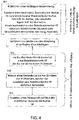
- FIG. 4 shows a flow chart of a method for determining the wear of a bush of a plain bearing.
- the method for determining the wear of a sleeve of a plain bearing has the following steps as an example.
- the measurement signal that is output can be processed and converted in various ways before it is output by means of a control and/or regulation unit, which includes a memory unit and a processor unit.
- the measurement signal can be converted into an acoustic signal, an optical signal or a haptic signal.
- step S11 a calibration of a plain bearing measuring arrangement, which in particular comprises a socket, a housing and a test plug 60, can take place.
- a step S01 for calibration can in particular include: calibrating a plain bearing measurement arrangement, with a specific condition of a bushing 10, such as wall thickness of the bushing, porosity of the bushing, or elastic Property of the socket, a certain electrically detectable measured value is assigned to the detector elements, such as current, voltage or capacity.
- Step S01 can be used to define, in particular, critical states of bushing 10, such as insufficient wall thickness of bushing 10 or insufficient wall thickness of sliding element 20, or excessive porosity of bushing 10 or sliding element 20.
- the plain bearing measuring arrangement can be calibrated in particular on the basis of simulations and/or real tests.
Landscapes
- Engineering & Computer Science (AREA)
- General Engineering & Computer Science (AREA)
- Mechanical Engineering (AREA)
- Sliding-Contact Bearings (AREA)
Applications Claiming Priority (1)
| Application Number | Priority Date | Filing Date | Title |
|---|---|---|---|
| DE102021206766.2A DE102021206766A1 (de) | 2021-06-29 | 2021-06-29 | Buchse für ein Gleitlager, Gleitlagermessanordnung und Verfahren |
Publications (2)
| Publication Number | Publication Date |
|---|---|
| EP4112954A1 true EP4112954A1 (fr) | 2023-01-04 |
| EP4112954B1 EP4112954B1 (fr) | 2025-02-26 |
Family
ID=82308486
Family Applications (1)
| Application Number | Title | Priority Date | Filing Date |
|---|---|---|---|
| EP22180874.4A Active EP4112954B1 (fr) | 2021-06-29 | 2022-06-24 | Douille pour un palier lisse, agencement de mesure de palier lisse et procédé |
Country Status (2)
| Country | Link |
|---|---|
| EP (1) | EP4112954B1 (fr) |
| DE (1) | DE102021206766A1 (fr) |
Cited By (1)
| Publication number | Priority date | Publication date | Assignee | Title |
|---|---|---|---|---|
| EP4686651A1 (fr) * | 2024-07-31 | 2026-02-04 | Airbus Operations Limited | Douille |
Citations (5)
| Publication number | Priority date | Publication date | Assignee | Title |
|---|---|---|---|---|
| EP0029736A1 (fr) * | 1979-11-26 | 1981-06-03 | Hitachi, Ltd. | Appareil et procédé de surveillance des conditions opérationnelles d'un palier |
| US4721399A (en) * | 1984-05-18 | 1988-01-26 | Braunschweiger Huttenwerk Gmbh | Plain bearing provided with a device for locally determining the temperature of its sliding |
| US6080982A (en) * | 1998-05-13 | 2000-06-27 | The United States Of America As Represented By The Secretary Of The Navy | Embedded wear sensor |
| EP1602842A1 (fr) * | 2004-06-04 | 2005-12-07 | Ab Skf | Palier à glissement avec capteur permettant de determiner l'usure d'une couche de glissement |
| DE202019101776U1 (de) * | 2019-03-28 | 2019-12-04 | Igus Gmbh | Kunststoff-Gleitelement mit Sensorfunktion, insbesondere mit Verschleißerkennung |
Family Cites Families (3)
| Publication number | Priority date | Publication date | Assignee | Title |
|---|---|---|---|---|
| DE202016102133U1 (de) | 2016-04-21 | 2017-05-23 | Igus Gmbh | Gleitlager, Kunststoffgleitelement, System und Verwendung zur Verschleißerkennung |
| DE102017218878A1 (de) | 2016-11-07 | 2018-05-24 | Aktiebolaget Skf | Verkabeltes Lager |
| DE102019129481A1 (de) | 2019-10-31 | 2021-05-06 | Rolls-Royce Deutschland Ltd & Co Kg | Vorrichtung und Verfahren zur Überwachung eines Gleitlagers |
-
2021
- 2021-06-29 DE DE102021206766.2A patent/DE102021206766A1/de active Pending
-
2022
- 2022-06-24 EP EP22180874.4A patent/EP4112954B1/fr active Active
Patent Citations (5)
| Publication number | Priority date | Publication date | Assignee | Title |
|---|---|---|---|---|
| EP0029736A1 (fr) * | 1979-11-26 | 1981-06-03 | Hitachi, Ltd. | Appareil et procédé de surveillance des conditions opérationnelles d'un palier |
| US4721399A (en) * | 1984-05-18 | 1988-01-26 | Braunschweiger Huttenwerk Gmbh | Plain bearing provided with a device for locally determining the temperature of its sliding |
| US6080982A (en) * | 1998-05-13 | 2000-06-27 | The United States Of America As Represented By The Secretary Of The Navy | Embedded wear sensor |
| EP1602842A1 (fr) * | 2004-06-04 | 2005-12-07 | Ab Skf | Palier à glissement avec capteur permettant de determiner l'usure d'une couche de glissement |
| DE202019101776U1 (de) * | 2019-03-28 | 2019-12-04 | Igus Gmbh | Kunststoff-Gleitelement mit Sensorfunktion, insbesondere mit Verschleißerkennung |
Cited By (1)
| Publication number | Priority date | Publication date | Assignee | Title |
|---|---|---|---|---|
| EP4686651A1 (fr) * | 2024-07-31 | 2026-02-04 | Airbus Operations Limited | Douille |
Also Published As
| Publication number | Publication date |
|---|---|
| DE102021206766A1 (de) | 2022-12-29 |
| EP4112954B1 (fr) | 2025-02-26 |
Similar Documents
| Publication | Publication Date | Title |
|---|---|---|
| DE202014011100U1 (de) | Großlager, insbesondere Hauptlager einer Windkraftanlage | |
| DE102016116113A1 (de) | Lager und Verfahren zur Verschleißüberwachung und/oder Lastmessung | |
| DE102016116118A1 (de) | Wälzkörper zur Verwendung in einem Wälzlager | |
| DE102011006907B4 (de) | Wälzkörper | |
| DE10324924B4 (de) | Verfahren zum Ermitteln einer von einem Gleitlager mit sphärisch oder zylindrisch ausgebildeten Lagerflächen aufgenommenen Last | |
| EP3857197B1 (fr) | Corps de roulement équipé d'un capteur et destiné à être utilisé dans un palier à roulement | |
| DE102018002221A1 (de) | Sensoreinrichtung zum Erfassen einer Formveränderung eines Batteriekörpers einer Fahrzeugbatterie sowie Verfahren zum Erfassen einer Formveränderung eines Batteriekörpers einer Fahrzeugbatterie | |
| EP3093641B1 (fr) | Procédé de détermination d'une force de traction axiale appliquée à un composant | |
| DE2947937C2 (de) | Verfahren und Vorrichtung zur Bestimmung von Wälzlagerschäden | |
| DE102017007857A1 (de) | Spindelvorrichtung zum Einsatz an einer numerisch gesteuerten Werkzeugmaschine | |
| DE102010045912A1 (de) | Rotierbares Wälzlager | |
| DE10302349B3 (de) | Kraftaufnehmer zum Messen von Achskräften | |
| EP3717806A1 (fr) | Système d'étanchéité | |
| EP2527809A1 (fr) | Dispositif de détection | |
| DE10217284B4 (de) | Vorrichtung zur Kontrolle von Schraubverbindungen | |
| DE102019218884B4 (de) | Großwälzlager und Verfahren zur Verschleißmessung | |
| EP4112954B1 (fr) | Douille pour un palier lisse, agencement de mesure de palier lisse et procédé | |
| DE10302352A1 (de) | Kraftaufnehmer zum Messen von Achskräften | |
| EP3913347B1 (fr) | Utilisation d'un dispositif de mesure pour détecter la déformation d'un tuyau en élastomère | |
| EP2415697B1 (fr) | Dispositif de transport et son procédé de surveillance | |
| WO2022194316A1 (fr) | Palier lisse et procédé pour surveiller l'état d'un palier lisse | |
| DE102012000332B3 (de) | Verfahren und Einrichtung zur Messung der Lichtspaltdichtigkeit von Kolbenringen | |
| DE102017112869B3 (de) | Messanordnung zur Erfassung von Käfigbelastungen | |
| EP4204699B1 (fr) | Element de palier doté d'un capteur et d'un dispositif de telemetrie | |
| EP4249855B1 (fr) | Capteur de rotation et procédé de fonctionnement d'un capteur de rotation |
Legal Events
| Date | Code | Title | Description |
|---|---|---|---|
| PUAI | Public reference made under article 153(3) epc to a published international application that has entered the european phase |
Free format text: ORIGINAL CODE: 0009012 |
|
| STAA | Information on the status of an ep patent application or granted ep patent |
Free format text: STATUS: THE APPLICATION HAS BEEN PUBLISHED |
|
| AK | Designated contracting states |
Kind code of ref document: A1 Designated state(s): AL AT BE BG CH CY CZ DE DK EE ES FI FR GB GR HR HU IE IS IT LI LT LU LV MC MK MT NL NO PL PT RO RS SE SI SK SM TR |
|
| STAA | Information on the status of an ep patent application or granted ep patent |
Free format text: STATUS: REQUEST FOR EXAMINATION WAS MADE |
|
| 17P | Request for examination filed |
Effective date: 20230629 |
|
| RBV | Designated contracting states (corrected) |
Designated state(s): AL AT BE BG CH CY CZ DE DK EE ES FI FR GB GR HR HU IE IS IT LI LT LU LV MC MK MT NL NO PL PT RO RS SE SI SK SM TR |
|
| RIC1 | Information provided on ipc code assigned before grant |
Ipc: F16C 17/02 20060101ALI20240222BHEP Ipc: F16C 17/24 20060101AFI20240222BHEP |
|
| GRAP | Despatch of communication of intention to grant a patent |
Free format text: ORIGINAL CODE: EPIDOSNIGR1 |
|
| STAA | Information on the status of an ep patent application or granted ep patent |
Free format text: STATUS: GRANT OF PATENT IS INTENDED |
|
| INTG | Intention to grant announced |
Effective date: 20240411 |
|
| GRAJ | Information related to disapproval of communication of intention to grant by the applicant or resumption of examination proceedings by the epo deleted |
Free format text: ORIGINAL CODE: EPIDOSDIGR1 |
|
| STAA | Information on the status of an ep patent application or granted ep patent |
Free format text: STATUS: REQUEST FOR EXAMINATION WAS MADE |
|
| INTC | Intention to grant announced (deleted) | ||
| GRAP | Despatch of communication of intention to grant a patent |
Free format text: ORIGINAL CODE: EPIDOSNIGR1 |
|
| STAA | Information on the status of an ep patent application or granted ep patent |
Free format text: STATUS: GRANT OF PATENT IS INTENDED |
|
| INTG | Intention to grant announced |
Effective date: 20240919 |
|
| GRAS | Grant fee paid |
Free format text: ORIGINAL CODE: EPIDOSNIGR3 |
|
| GRAA | (expected) grant |
Free format text: ORIGINAL CODE: 0009210 |
|
| STAA | Information on the status of an ep patent application or granted ep patent |
Free format text: STATUS: THE PATENT HAS BEEN GRANTED |
|
| AK | Designated contracting states |
Kind code of ref document: B1 Designated state(s): AL AT BE BG CH CY CZ DE DK EE ES FI FR GB GR HR HU IE IS IT LI LT LU LV MC MK MT NL NO PL PT RO RS SE SI SK SM TR |
|
| REG | Reference to a national code |
Ref country code: GB Ref legal event code: FG4D Free format text: NOT ENGLISH |
|
| REG | Reference to a national code |
Ref country code: CH Ref legal event code: EP |
|
| REG | Reference to a national code |
Ref country code: DE Ref legal event code: R096 Ref document number: 502022002996 Country of ref document: DE |
|
| REG | Reference to a national code |
Ref country code: DE Ref legal event code: R081 Ref document number: 502022002996 Country of ref document: DE Owner name: YAMAICHI ELECTRONICS DEUTSCHLAND GMBH, DE Free format text: FORMER OWNER: ANMELDERANGABEN UNKLAR / UNVOLLSTAENDIG, 80297 MUENCHEN, DE |
|
| REG | Reference to a national code |
Ref country code: IE Ref legal event code: FG4D Free format text: LANGUAGE OF EP DOCUMENT: GERMAN |
|
| REG | Reference to a national code |
Ref country code: NL Ref legal event code: MP Effective date: 20250226 |
|
| PG25 | Lapsed in a contracting state [announced via postgrant information from national office to epo] |
Ref country code: RS Free format text: LAPSE BECAUSE OF FAILURE TO SUBMIT A TRANSLATION OF THE DESCRIPTION OR TO PAY THE FEE WITHIN THE PRESCRIBED TIME-LIMIT Effective date: 20250526 |
|
| PG25 | Lapsed in a contracting state [announced via postgrant information from national office to epo] |
Ref country code: FI Free format text: LAPSE BECAUSE OF FAILURE TO SUBMIT A TRANSLATION OF THE DESCRIPTION OR TO PAY THE FEE WITHIN THE PRESCRIBED TIME-LIMIT Effective date: 20250226 |
|
| PG25 | Lapsed in a contracting state [announced via postgrant information from national office to epo] |
Ref country code: PL Free format text: LAPSE BECAUSE OF FAILURE TO SUBMIT A TRANSLATION OF THE DESCRIPTION OR TO PAY THE FEE WITHIN THE PRESCRIBED TIME-LIMIT Effective date: 20250226 |
|
| PGFP | Annual fee paid to national office [announced via postgrant information from national office to epo] |
Ref country code: DE Payment date: 20250626 Year of fee payment: 4 |
|
| PG25 | Lapsed in a contracting state [announced via postgrant information from national office to epo] |
Ref country code: ES Free format text: LAPSE BECAUSE OF FAILURE TO SUBMIT A TRANSLATION OF THE DESCRIPTION OR TO PAY THE FEE WITHIN THE PRESCRIBED TIME-LIMIT Effective date: 20250226 |
|
| REG | Reference to a national code |
Ref country code: LT Ref legal event code: MG9D |
|
| PG25 | Lapsed in a contracting state [announced via postgrant information from national office to epo] |
Ref country code: IS Free format text: LAPSE BECAUSE OF FAILURE TO SUBMIT A TRANSLATION OF THE DESCRIPTION OR TO PAY THE FEE WITHIN THE PRESCRIBED TIME-LIMIT Effective date: 20250626 Ref country code: NO Free format text: LAPSE BECAUSE OF FAILURE TO SUBMIT A TRANSLATION OF THE DESCRIPTION OR TO PAY THE FEE WITHIN THE PRESCRIBED TIME-LIMIT Effective date: 20250526 |
|
| PG25 | Lapsed in a contracting state [announced via postgrant information from national office to epo] |
Ref country code: NL Free format text: LAPSE BECAUSE OF FAILURE TO SUBMIT A TRANSLATION OF THE DESCRIPTION OR TO PAY THE FEE WITHIN THE PRESCRIBED TIME-LIMIT Effective date: 20250226 |
|
| PG25 | Lapsed in a contracting state [announced via postgrant information from national office to epo] |
Ref country code: HR Free format text: LAPSE BECAUSE OF FAILURE TO SUBMIT A TRANSLATION OF THE DESCRIPTION OR TO PAY THE FEE WITHIN THE PRESCRIBED TIME-LIMIT Effective date: 20250226 |
|
| PG25 | Lapsed in a contracting state [announced via postgrant information from national office to epo] |
Ref country code: PT Free format text: LAPSE BECAUSE OF FAILURE TO SUBMIT A TRANSLATION OF THE DESCRIPTION OR TO PAY THE FEE WITHIN THE PRESCRIBED TIME-LIMIT Effective date: 20250626 Ref country code: LV Free format text: LAPSE BECAUSE OF FAILURE TO SUBMIT A TRANSLATION OF THE DESCRIPTION OR TO PAY THE FEE WITHIN THE PRESCRIBED TIME-LIMIT Effective date: 20250226 |
|
| PGFP | Annual fee paid to national office [announced via postgrant information from national office to epo] |
Ref country code: FR Payment date: 20250626 Year of fee payment: 4 |
|
| PG25 | Lapsed in a contracting state [announced via postgrant information from national office to epo] |
Ref country code: BG Free format text: LAPSE BECAUSE OF FAILURE TO SUBMIT A TRANSLATION OF THE DESCRIPTION OR TO PAY THE FEE WITHIN THE PRESCRIBED TIME-LIMIT Effective date: 20250226 Ref country code: GR Free format text: LAPSE BECAUSE OF FAILURE TO SUBMIT A TRANSLATION OF THE DESCRIPTION OR TO PAY THE FEE WITHIN THE PRESCRIBED TIME-LIMIT Effective date: 20250527 |
|
| PGFP | Annual fee paid to national office [announced via postgrant information from national office to epo] |
Ref country code: AT Payment date: 20250721 Year of fee payment: 4 |
|
| PG25 | Lapsed in a contracting state [announced via postgrant information from national office to epo] |
Ref country code: SE Free format text: LAPSE BECAUSE OF FAILURE TO SUBMIT A TRANSLATION OF THE DESCRIPTION OR TO PAY THE FEE WITHIN THE PRESCRIBED TIME-LIMIT Effective date: 20250226 |
|
| PG25 | Lapsed in a contracting state [announced via postgrant information from national office to epo] |
Ref country code: SM Free format text: LAPSE BECAUSE OF FAILURE TO SUBMIT A TRANSLATION OF THE DESCRIPTION OR TO PAY THE FEE WITHIN THE PRESCRIBED TIME-LIMIT Effective date: 20250226 |
|
| PG25 | Lapsed in a contracting state [announced via postgrant information from national office to epo] |
Ref country code: DK Free format text: LAPSE BECAUSE OF FAILURE TO SUBMIT A TRANSLATION OF THE DESCRIPTION OR TO PAY THE FEE WITHIN THE PRESCRIBED TIME-LIMIT Effective date: 20250226 |
|
| PG25 | Lapsed in a contracting state [announced via postgrant information from national office to epo] |
Ref country code: IT Free format text: LAPSE BECAUSE OF FAILURE TO SUBMIT A TRANSLATION OF THE DESCRIPTION OR TO PAY THE FEE WITHIN THE PRESCRIBED TIME-LIMIT Effective date: 20250226 |
|
| PG25 | Lapsed in a contracting state [announced via postgrant information from national office to epo] |
Ref country code: EE Free format text: LAPSE BECAUSE OF FAILURE TO SUBMIT A TRANSLATION OF THE DESCRIPTION OR TO PAY THE FEE WITHIN THE PRESCRIBED TIME-LIMIT Effective date: 20250226 Ref country code: CZ Free format text: LAPSE BECAUSE OF FAILURE TO SUBMIT A TRANSLATION OF THE DESCRIPTION OR TO PAY THE FEE WITHIN THE PRESCRIBED TIME-LIMIT Effective date: 20250226 |
|
| PG25 | Lapsed in a contracting state [announced via postgrant information from national office to epo] |
Ref country code: RO Free format text: LAPSE BECAUSE OF FAILURE TO SUBMIT A TRANSLATION OF THE DESCRIPTION OR TO PAY THE FEE WITHIN THE PRESCRIBED TIME-LIMIT Effective date: 20250226 |
|
| PG25 | Lapsed in a contracting state [announced via postgrant information from national office to epo] |
Ref country code: SK Free format text: LAPSE BECAUSE OF FAILURE TO SUBMIT A TRANSLATION OF THE DESCRIPTION OR TO PAY THE FEE WITHIN THE PRESCRIBED TIME-LIMIT Effective date: 20250226 |
|
| REG | Reference to a national code |
Ref country code: DE Ref legal event code: R097 Ref document number: 502022002996 Country of ref document: DE |
|
| PLBE | No opposition filed within time limit |
Free format text: ORIGINAL CODE: 0009261 |
|
| STAA | Information on the status of an ep patent application or granted ep patent |
Free format text: STATUS: NO OPPOSITION FILED WITHIN TIME LIMIT |
|
| REG | Reference to a national code |
Ref country code: CH Ref legal event code: L10 Free format text: ST27 STATUS EVENT CODE: U-0-0-L10-L00 (AS PROVIDED BY THE NATIONAL OFFICE) Effective date: 20260107 |
|
| REG | Reference to a national code |
Ref country code: CH Ref legal event code: H13 Free format text: ST27 STATUS EVENT CODE: U-0-0-H10-H13 (AS PROVIDED BY THE NATIONAL OFFICE) Effective date: 20260127 |
|
| PG25 | Lapsed in a contracting state [announced via postgrant information from national office to epo] |
Ref country code: MC Free format text: LAPSE BECAUSE OF FAILURE TO SUBMIT A TRANSLATION OF THE DESCRIPTION OR TO PAY THE FEE WITHIN THE PRESCRIBED TIME-LIMIT Effective date: 20250226 |
|
| 26N | No opposition filed |
Effective date: 20251127 |
|
| PG25 | Lapsed in a contracting state [announced via postgrant information from national office to epo] |
Ref country code: LU Free format text: LAPSE BECAUSE OF NON-PAYMENT OF DUE FEES Effective date: 20250624 |
|
| REG | Reference to a national code |
Ref country code: BE Ref legal event code: MM Effective date: 20250630 |
|
| PG25 | Lapsed in a contracting state [announced via postgrant information from national office to epo] |
Ref country code: IE Free format text: LAPSE BECAUSE OF NON-PAYMENT OF DUE FEES Effective date: 20250624 |
|
| PG25 | Lapsed in a contracting state [announced via postgrant information from national office to epo] |
Ref country code: BE Free format text: LAPSE BECAUSE OF NON-PAYMENT OF DUE FEES Effective date: 20250630 |
|
| PG25 | Lapsed in a contracting state [announced via postgrant information from national office to epo] |
Ref country code: CH Free format text: LAPSE BECAUSE OF NON-PAYMENT OF DUE FEES Effective date: 20250630 |