EP4113014B1 - Système de revêtement doté d'un dispositif de chauffage et/ou de refroidissement - Google Patents
Système de revêtement doté d'un dispositif de chauffage et/ou de refroidissement Download PDFInfo
- Publication number
- EP4113014B1 EP4113014B1 EP22181706.7A EP22181706A EP4113014B1 EP 4113014 B1 EP4113014 B1 EP 4113014B1 EP 22181706 A EP22181706 A EP 22181706A EP 4113014 B1 EP4113014 B1 EP 4113014B1
- Authority
- EP
- European Patent Office
- Prior art keywords
- cladding system
- heat
- designed
- base
- latching
- Prior art date
- Legal status (The legal status is an assumption and is not a legal conclusion. Google has not performed a legal analysis and makes no representation as to the accuracy of the status listed.)
- Active
Links
Images


Classifications
-
- F—MECHANICAL ENGINEERING; LIGHTING; HEATING; WEAPONS; BLASTING
- F24—HEATING; RANGES; VENTILATING
- F24D—DOMESTIC- OR SPACE-HEATING SYSTEMS, e.g. CENTRAL HEATING SYSTEMS; DOMESTIC HOT-WATER SUPPLY SYSTEMS; ELEMENTS OR COMPONENTS THEREFOR
- F24D3/00—Hot-water central heating systems
- F24D3/12—Tube and panel arrangements for ceiling, wall, or underfloor heating
- F24D3/16—Tube and panel arrangements for ceiling, wall, or underfloor heating mounted on, or adjacent to, a ceiling, wall or floor
-
- F—MECHANICAL ENGINEERING; LIGHTING; HEATING; WEAPONS; BLASTING
- F24—HEATING; RANGES; VENTILATING
- F24D—DOMESTIC- OR SPACE-HEATING SYSTEMS, e.g. CENTRAL HEATING SYSTEMS; DOMESTIC HOT-WATER SUPPLY SYSTEMS; ELEMENTS OR COMPONENTS THEREFOR
- F24D3/00—Hot-water central heating systems
- F24D3/12—Tube and panel arrangements for ceiling, wall, or underfloor heating
- F24D3/16—Tube and panel arrangements for ceiling, wall, or underfloor heating mounted on, or adjacent to, a ceiling, wall or floor
- F24D3/165—Suspended radiant heating ceiling
-
- E—FIXED CONSTRUCTIONS
- E04—BUILDING
- E04B—GENERAL BUILDING CONSTRUCTIONS; WALLS, e.g. PARTITIONS; ROOFS; FLOORS; CEILINGS; INSULATION OR OTHER PROTECTION OF BUILDINGS
- E04B9/00—Ceilings; Construction of ceilings, e.g. false ceilings; Ceiling construction with regard to insulation
- E04B9/06—Ceilings; Construction of ceilings, e.g. false ceilings; Ceiling construction with regard to insulation characterised by constructional features of the supporting construction, e.g. cross section or material of framework members
- E04B9/12—Connections between non-parallel members of the supporting construction
- E04B9/16—Connections between non-parallel members of the supporting construction the members lying in different planes
-
- E—FIXED CONSTRUCTIONS
- E04—BUILDING
- E04B—GENERAL BUILDING CONSTRUCTIONS; WALLS, e.g. PARTITIONS; ROOFS; FLOORS; CEILINGS; INSULATION OR OTHER PROTECTION OF BUILDINGS
- E04B9/00—Ceilings; Construction of ceilings, e.g. false ceilings; Ceiling construction with regard to insulation
- E04B9/18—Means for suspending the supporting construction
- E04B9/20—Means for suspending the supporting construction adjustable
-
- E—FIXED CONSTRUCTIONS
- E04—BUILDING
- E04B—GENERAL BUILDING CONSTRUCTIONS; WALLS, e.g. PARTITIONS; ROOFS; FLOORS; CEILINGS; INSULATION OR OTHER PROTECTION OF BUILDINGS
- E04B9/00—Ceilings; Construction of ceilings, e.g. false ceilings; Ceiling construction with regard to insulation
- E04B9/22—Connection of slabs, panels, sheets or the like to the supporting construction
- E04B9/24—Connection of slabs, panels, sheets or the like to the supporting construction with the slabs, panels, sheets or the like positioned on the upperside of, or held against the underside of the horizontal flanges of the supporting construction or accessory means connected thereto
- E04B9/245—Connection of slabs, panels, sheets or the like to the supporting construction with the slabs, panels, sheets or the like positioned on the upperside of, or held against the underside of the horizontal flanges of the supporting construction or accessory means connected thereto by means of screws, bolts or clamping strips held against the underside of the supporting construction
-
- E—FIXED CONSTRUCTIONS
- E04—BUILDING
- E04B—GENERAL BUILDING CONSTRUCTIONS; WALLS, e.g. PARTITIONS; ROOFS; FLOORS; CEILINGS; INSULATION OR OTHER PROTECTION OF BUILDINGS
- E04B9/00—Ceilings; Construction of ceilings, e.g. false ceilings; Ceiling construction with regard to insulation
- E04B9/22—Connection of slabs, panels, sheets or the like to the supporting construction
- E04B9/24—Connection of slabs, panels, sheets or the like to the supporting construction with the slabs, panels, sheets or the like positioned on the upperside of, or held against the underside of the horizontal flanges of the supporting construction or accessory means connected thereto
- E04B9/26—Connection of slabs, panels, sheets or the like to the supporting construction with the slabs, panels, sheets or the like positioned on the upperside of, or held against the underside of the horizontal flanges of the supporting construction or accessory means connected thereto by means of snap action of elastically deformable elements held against the underside of the supporting construction
-
- F—MECHANICAL ENGINEERING; LIGHTING; HEATING; WEAPONS; BLASTING
- F24—HEATING; RANGES; VENTILATING
- F24D—DOMESTIC- OR SPACE-HEATING SYSTEMS, e.g. CENTRAL HEATING SYSTEMS; DOMESTIC HOT-WATER SUPPLY SYSTEMS; ELEMENTS OR COMPONENTS THEREFOR
- F24D3/00—Hot-water central heating systems
- F24D3/12—Tube and panel arrangements for ceiling, wall, or underfloor heating
- F24D3/14—Tube and panel arrangements for ceiling, wall, or underfloor heating incorporated in a ceiling, wall or floor
- F24D3/148—Tube and panel arrangements for ceiling, wall, or underfloor heating incorporated in a ceiling, wall or floor with heat spreading plates
-
- F—MECHANICAL ENGINEERING; LIGHTING; HEATING; WEAPONS; BLASTING
- F24—HEATING; RANGES; VENTILATING
- F24F—AIR-CONDITIONING; AIR-HUMIDIFICATION; VENTILATION; USE OF AIR CURRENTS FOR SCREENING
- F24F5/00—Air-conditioning systems or apparatus not covered by F24F1/00 or F24F3/00, e.g. using solar heat or combined with household units such as an oven or water heater
- F24F5/0089—Systems using radiation from walls or panels
-
- F—MECHANICAL ENGINEERING; LIGHTING; HEATING; WEAPONS; BLASTING
- F24—HEATING; RANGES; VENTILATING
- F24F—AIR-CONDITIONING; AIR-HUMIDIFICATION; VENTILATION; USE OF AIR CURRENTS FOR SCREENING
- F24F5/00—Air-conditioning systems or apparatus not covered by F24F1/00 or F24F3/00, e.g. using solar heat or combined with household units such as an oven or water heater
- F24F5/0089—Systems using radiation from walls or panels
- F24F5/0092—Systems using radiation from walls or panels ceilings, e.g. cool ceilings
-
- E—FIXED CONSTRUCTIONS
- E04—BUILDING
- E04B—GENERAL BUILDING CONSTRUCTIONS; WALLS, e.g. PARTITIONS; ROOFS; FLOORS; CEILINGS; INSULATION OR OTHER PROTECTION OF BUILDINGS
- E04B9/00—Ceilings; Construction of ceilings, e.g. false ceilings; Ceiling construction with regard to insulation
- E04B9/04—Ceilings; Construction of ceilings, e.g. false ceilings; Ceiling construction with regard to insulation comprising slabs, panels, sheets or the like
- E04B9/0421—Ceilings; Construction of ceilings, e.g. false ceilings; Ceiling construction with regard to insulation comprising slabs, panels, sheets or the like comprising ducts
Definitions
- the present invention relates to a cladding system with a heating and/or cooling device.
- ES 2 331 674 A1 discloses climate profiles as extruded aluminum profiles with a recess for receiving climate pipes, which are inserted via a substructure in a suspended heating and/or cooling ceiling. An additional closure is provided to fix the air conditioning pipes in these recesses.
- a wall and ceiling cladding with a heating and/or cooling device in the form of an air conditioning pipe through which an appropriately tempered fluid flows is known.
- the air conditioning pipe is fixed in a heat-conducting profile, which in turn is fastened with several heat-conducting profiles arranged parallel to one another in a bracket that runs perpendicular to the heat-conducting profiles and is suspended at end pieces between two parallel mounting rails.
- the support rails are attached to parallel support beams at constant intervals and form a substructure fixed to a wall or ceiling, as is generally known to those skilled in the art as a so-called stud frame from drywall construction.
- Cladding panels are attached to a plane formed by the support rails and the heat-conducting profiles, in particular in the form of gypsum-cardboard panels.
- the DE 201 06 884 U1 describes a ceiling structure with heat-conducting profiles in which a pipe is arranged in a bead and clamped.
- the heat-conducting profiles are designed in the form of sheet metal strips, which, among other things, are angled Have sections which are provided by forming hanging or holding sections for hanging on a base or a fine grid of a ceiling structure fixed to it.
- EP 2 653 792 B1 discloses the formation of hooks in the area of grooves in a sheet metal strip that are open downwards in an installed position, the grooves in turn serving to clamp a pipeline.
- a mounting rail as a system rail with connecting elements integrally integrated thereon, which is designed as stamped and bent parts for snapping in heat-conducting profiles provided with corresponding locking lugs.
- These mounting rails are suitable for direct mounting on a mounting surface, i.e. a wall or a ceiling.
- This mounting rail and the heat-conducting profiles are made from roll-formed sheet steel strips. This system has basically proven itself.
- the present invention has the object of creating a cladding system with a heating and/or cooling device which has further improved properties.
- a cladding system with a support device and heating and / or cooling device, in which an air conditioning pipe in an approximately omega-shaped receptacle Heat-conducting profile is fixed and the heat-conducting profile made of roll-formed sheet metal can be attached to a wall or a ceiling via the support device, the heat-conducting profile being designed in such a way that the air-conditioning tube is pressed in with reversibly resilient expansion of the approximately omega-shaped receptacle and in the heat-conducting profile with good thermal connection is permanently fixed, and the heat-conducting profile has at least one locking lug in an outer area of the approximately omega-shaped receptacle and a corresponding resilient locking arm is provided on the support device.
- the heat-conducting profile made of roll-formed sheet metal is redesigned according to the invention in such a way that at least one locking lug is now provided in an outer area of the approximately omega-shaped receptacle, instead of at least one known locking arm or hook of comparatively large length.
- a quick and secure locking mechanism can be produced on a support device in that a support device now has a spring-elastic locking arm corresponding to this locking lug of the heat-conducting profile. Fixing in the form of a latching is superior to simply hanging a heat-conducting profile on a ceiling substructure from a safety perspective.
- a design according to the invention of a heat-conducting profile has a significantly simplified cross-sectional area with sufficient bending rigidity to prevent sagging in one Installation position.
- a portion of the surface of the heat-conducting profile is increased, which is effectively used for heat transport in interaction with a room to be air-conditioned.
- An arbitrarily selectable length of an air-conditioning pipe can, for example, be laid in a meandering shape over heat-conducting profile sections that are fixed parallel to one another on a ceiling and cut to length as required to optimize coverage of every conceivable surface shape of a wall or ceiling.
- the heat-conducting profile has, in an outer area of the approximately omega-shaped receptacle, two latching lugs arranged in a mirror-symmetrical manner with respect to a central axis of the approximately omega-shaped receptacle, and two latching arms are provided in a mirror-symmetrical manner on the support device.
- latches are provided on both sides of the approximately omega-shaped receptacle as secure fixations.
- these locking arms are designed to partially encompass the approximately omega-shaped receptacle of the heat-conducting profile. This feature makes the approximately omega-shaped mount equally more resilient Arms created to apply symmetrical force to the heat-conducting profile in the area of the holder.
- the heat-conducting profile continuously has two formed and mirror-symmetrically arranged locking lugs in an outer area of the approximately omega-shaped receptacle, with two mirror-symmetrical locking arms partially encompassing the approximately omega-shaped receptacle of the heat-conducting profile being provided on the support device, which are designed in the form of defined sections on the support device.
- the support device thus forms a symmetrical load for the heat-conducting profile, which essentially only acts at points over a length of a heat-conducting profile.
- the carrying device is designed as a clip made of plastic.
- the heat-conducting profile made of highly thermally conductive aluminum in contact with the plastic of the clip which significantly inhibits the outflow of heat or cold, is advantageously largely decoupled from the rest of the substructure of the wall or ceiling cladding.
- a heat flow can therefore essentially only run between the heat-conducting profile and the air conditioning pipe fixed therein. The release or absorption of heat is therefore better concentrated on the heat-conducting profile.
- Plastic parts are also very advantageous in terms of weight and also manufacturing costs for larger quantities in terms of their comparatively low production costs, even with more complex shapes, and sufficiently high mechanical strength and corrosion resistance compared to stamped and bent parts made of sheet metal.
- the latching arms of the support device open into a base.
- this base is formed on the support device in a fully installed state in the area of the approximately omega-shaped receptacle of the heat-conducting profile.
- locking arms are then provided on the base of the support device and are designed to lock the support device on a support rail.
- the carrying device therefore has an advantageous locking dual function.
- the locking arms of the carrying device also have predetermined breaking points. These predetermined breaking points are designed for the targeted removal of these latching arms from the base, so that a base of the support device can also be fixed directly to a wall or ceiling instead of latching to a support of a ceiling substructure.
- the base also has a recess through which the carrying device can be directly fixed, in particular screwed, via the base.
- the carrying device is designed to be height-adjustable.
- this height adjustment is realized via a screw connection on the base, through which, in addition to setting up a predetermined distance, smaller to larger tolerances, for example between a ceiling surface and a heat-conducting profile, can be compensated for easily and without the use of additional tools.
- a base plate is provided on a T-piece of the screw connection, which is designed for direct attachment to a wall.
- the Invention radially distributed recesses and/or a central recess are provided in the base plate of the T-piece for carrying out screw connections.
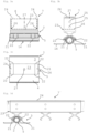
- Figure 5 shows two designs of a known cladding system 1 of a ceiling, not shown, in a side view.
- the wall and ceiling cladding shown is equipped as a cladding system 1 with a heating and/or cooling device in the form of an air conditioning pipe 2, through which an appropriately tempered fluid flows.
- two air conditioning pipes 2 are fixed in a heat-conducting profile 3, the heat-conducting profile 3 being a roll-formed galvanized steel sheet having several sections: a first horizontal section 4a, which has a part of an omega-shaped receptacle 5 for a first air conditioning pipe 2 in a locking arm 6 and continues in one piece from there to a second part of the omega-shaped receptacle 5 back into a central horizontal section 4b, to which there is another omega-shaped receptacle 5 for a second air conditioning pipe 2 with a locking arm 6 and a final horizontal section 4c connects.
- a first horizontal section 4a which has a part of an omega-shaped receptacle 5 for a first air conditioning pipe 2 in a locking arm 6 and continues in one piece from there to a second part of the omega-shaped receptacle 5 back into a central horizontal section 4b, to which there is another omega-shaped receptacle 5 for a second air conditioning pipe 2 with a locking arm 6 and a final
- the omega-shaped receptacles 5 are resilient to such an extent that an air conditioning pipe 2 is pressed through their opening and is held permanently and securely over a length of the heat-conducting profile 3.
- This heat-conducting profile 3 is constructed in mirror image to a central axis M, so the locking arms 6 are each aligned in opposite locking directions.
- FIG 5 Two known types of self-locking suspension of the heat-conducting profiles 3, each equipped with two air conditioning pipes 2, on a support device 7 are shown:
- the upper half of Figure 5 has one of several mounting rails 8 running parallel to one another at certain distances approximately T-shaped punched out 9 bent up by approximately 90 °, the punched out 9 also being symmetrical. Free ends 10 of this punched out 9 serve as locking lugs on which the locking arms 6 of the heat-conducting profile 3 engage in a resilient manner.
- This arrangement essentially corresponds to the teaching of DE 20 2018 103 991 U1 .
- a U-shaped anchor bracket 11 is arranged on the mounting rail 9 so that it can be moved horizontally in the manner indicated by the double arrow.
- the anchor angle 11 also has T-shaped legs 12 with free ends 10 as a sheet metal body. As described above, these ends 10 in turn serve as locking lugs for resilient engagement of the locking arms 6 of the heat-conducting profile 3.
- the mounting rail 8 is suspended here from a surface of a ceiling (not shown) by a so-called vernier bracket 13.
- support rails 8 are fixed to the ceiling in this way at constant distances parallel to one another.
- Such ceiling substructures using standard parts are generally known to those skilled in the drywall construction sector in terms of their dimensions and design and will therefore not be described further here, since exemplary embodiments according to the invention can also be seamlessly integrated into this area.
- the sections 4a, 4b, 4c form a flat horizontal surface 4 on the heat-conducting profile 3 with a free outside 14, which creates a distance d from the mounting rail 8.
- a thin layer of gypsum-cardboard panels 15 is fixed to this free outside 14 as a uniform finish to the cladding system 1.
- a firm connection of the layer of gypsum cardboard 15 to a wall 16 is formed here by a U-profile 17.
- FIG 1 represents a sectional view of a first exemplary embodiment of a novel cladding system 1 analogous to the view of Figure 5 which has further improved properties compared to the prior art described above.
- the heat-conducting profile 3 is designed as a roll-formed sheet of galvanized steel with an approximately omega-shaped receptacle 5 for an air conditioning pipe 2.
- Elongated holes 20 have been added, which serve as an effective means of positively influencing room acoustics.
- FIG. 1 A further improvement in room acoustics is achieved if in the sectional view of Figure 1
- recesses aligned with the elongated holes 20 are also provided in the gypsum-cardboard board 15, which, after a finished construction of the cladding system 1, is fixed to the free outside 14 of the horizontal surface 4 of the heat-conducting profile 3, preferably by screw connections, as is already the case in Figure 5 shown and described.
- the spring elasticity of the heat-conducting profile 3 is basically sufficient for pressing in the air conditioning pipe 2 and subsequently holding it securely and permanently.
- the air conditioning pipe 2 can be inserted or pressed in without any problems in a known manner with reversibly elastic expansion of the approximately omega-shaped receptacle 5 of the heat-conducting profile 3 and permanently in the heat-conducting profile 3 with a good thermal connection be fixed. If an increase in the spring elasticity of the receptacle 5 is nevertheless desired, the formation of an additional spring-groove 19 in the area of a central axis M is advisable, as in Figure 1 indicated by dots.
- the heat-conducting profile 3 has two mirror-symmetrical ones on the approximately omega-shaped receptacle 5 Locking lugs 21 arranged on a central axis M.
- the locking lugs 21 replace the locking arm 6 of Figure 5 and are designed to engage on locking lugs 22 of a carrying device 7.
- the thermal conduction profile 3 from Figure 1 has a thermally active surface that is compared to the known design of Figure 5 is significantly enlarged compared to an overall surface.
- a corresponding spring-elastic locking arm 22 is provided on the associated support device 7, as in Figure 2 shown.
- This second exemplary embodiment thus represents a reversal of the prior art Figure 5
- two mirror-symmetrical locking arms 22 are provided on the support device 7 and partially surround the approximately omega-shaped receptacle 5 of the heat-conducting profile 3, at least on the locking lugs 21 and are designed here as two sections, as shown in the perspective view of the cladding system Figure 2 is shown.
- locking arms 22 end in a base 23. Opposite the locking arms 22, locking arms 24 are then provided on this base 23, which are designed to lock the support device 7 on the support rail 8, not shown.
- the carrying device 7 is thus designed to form a cross connection between a mounting rail 8 and the heat-conducting profile 3. Recesses 25 are also provided in the locking arms 24, through which the locking arms 24 can also be fixed to the mounting rail 8.
- This mounting rail 8 represents a standard drywall component and is therefore not shown further here.
- the carrying device 7 additionally has predetermined breaking points 26, which are designed for the targeted removal of these locking arms 24 from the base 23.
- a central recess 27 is provided in the base 23, through which a screw connection can be defined and carried out safely.
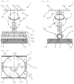
- Figures 3a to 3d additionally shows three views of the first exemplary embodiment of a cladding system 1 according to Figure 1 and additionally a modification in the form of a multiple carrying device.
- the carrying device 7 is designed as a clip made of plastic, which gives a shape design additional degrees of freedom compared to stamped and bent parts made of sheet metal. Accordingly, when the entire support device 7 is designed in one piece, the locking arms 22 open into a base 23, which is provided in an installed position in particular in the area of the tongue-and-groove 19.
- FIGS 4a to 4c are views of a second exemplary embodiment of a cladding system 1 in three representations analogous to the illustrations Figures 3a to 3c .
- the carrying device 7 is designed in two parts and is height-adjustable, which is realized here by a screw connection 28.
- the base 23 is rotatably fixed in a height-adjustable manner on a T-piece 29 with a slight incline, as indicated by arrows in the figures.
- the T-piece 29 in turn is designed for direct attachment to a wall, for example.
- radially distributed openings 30 are provided on a base plate 31 of the T-piece 29.
- Both components of the carrying device 7 are here again designed as plastic parts that are manufactured in an injection molding process. From the base 23 to the heat-conducting profile 3, the supporting device 7 is then constructed as already shown and described for the second exemplary embodiment.
- the carrying device 7 it is preferred to make the carrying device 7 as one piece as possible in plastic.
- the anchor angle 11 can also be manufactured as a U-shaped bracket made of plastic, instead of using the already known component made of sheet metal.
- the carrying device 7 thus acts across the exemplary embodiments as a thermal decoupling of the heat-conducting profile 3 relative to a mounting rail 8 with a possibly adjoining substructure, as is usually constructed from standardized metal parts adapted to a respective application in a manner known to those skilled in the art.
Landscapes
- Engineering & Computer Science (AREA)
- Architecture (AREA)
- Physics & Mathematics (AREA)
- Chemical & Material Sciences (AREA)
- Combustion & Propulsion (AREA)
- Mechanical Engineering (AREA)
- General Engineering & Computer Science (AREA)
- Thermal Sciences (AREA)
- Electromagnetism (AREA)
- Civil Engineering (AREA)
- Structural Engineering (AREA)
- Sustainable Development (AREA)
- Life Sciences & Earth Sciences (AREA)
- Domestic Hot-Water Supply Systems And Details Of Heating Systems (AREA)
- Devices For Blowing Cold Air, Devices For Blowing Warm Air, And Means For Preventing Water Condensation In Air Conditioning Units (AREA)
Claims (14)
- Système de revêtement (1) avec un dispositif de support (7) et un dispositif de chauffage et/ou de refroidissement, dans lequel un tube de climatisation (2) est fixé dans un logement (5) approximativement en forme d'oméga d'un profilé conducteur de chaleur (3) etle profilé conducteur de chaleur (3) en tôle formée par roulage peut être fixé à un mur ou à un plafond par l'intermédiaire du dispositif de support (7),le profilé conducteur de chaleur (3) étant conçu de telle sorte que le tube de climatisation (2) est enfoncé dans le logement (5) approximativement en forme d'oméga en s'élargissant de manière réversible et élastique et est fixé durablement dans le profilé conducteur de chaleur (3) avec une bonne liaison thermique,caractérisé en ce quele profilé conducteur de chaleur (3) dans une zone extérieure du logement (5) approximativement en forme d'oméga présente au moins un ergot d'arrêt (21) etun bras d'encliquetage (22) élastique correspondant à l'ergot d'encliquetage (21) est prévu sur le dispositif de support (7).
- Système de revêtement (1) selon la revendication précédente, caractérisé en ce que le profilé conducteur de chaleur (3) présente, dans une zone extérieure du logement (5) approximativement en forme d'oméga, deux ergots d'encliquetage (21) disposés de manière symétrique par rapport à un axe central du logement (5) approximativement en forme d'oméga, et en ce que les ergots d'encliquetage (21) sont disposés de manière symétrique par rapport au logement (5) approximativement en forme d'oméga et
deux bras d'encliquetage (22) conçus de manière à correspondre aux ergots d'encliquetage (21) sont prévus sur le dispositif de support (7). - Système de revêtement (1) selon la revendication précédente, caractérisé en ce que les bras d'encliquetage (22) sont réalisés de manière à entourer partiellement le logement (5) approximativement en forme d'oméga du profilé conducteur de chaleur (3).
- Système de revêtement (1) selon la revendication précédente, caractérisé en ce que les bras d'encliquetage (22) sont réalisés sous la forme de sections définies sur le dispositif de support (7).
- Système de revêtement (1) selon l'une des revendications précédentes, caractérisé en ce que le dispositif de support (7) est conçu comme un clip en matière plastique.
- Système de revêtement (1) selon l'une des revendications précédentes, caractérisé en ce que les bras d'encliquetage (22) du dispositif de support (7) débouchent dans une base (23) .
- Système de revêtement (1) selon la revendication précédente, caractérisé en ce que la base (23) est formée sur le dispositif de support (7) dans un état de montage fini dans la zone du logement approximativement en forme d'oméga (5) du profilé conducteur de chaleur (3).
- Système de revêtement (1) selon l'une des deux revendications précédentes, caractérisé en ce que des bras d'encliquetage (24) du dispositif de support (7) sont prévus à la suite de la base (23), qui sont conçus pour encliqueter le dispositif de support (7) sur un rail de support (8).
- Système de revêtement (1) selon la revendication précédente, caractérisé en ce que les bras d'encliquetage (24) du dispositif de support (7) présentent des points destinés à la rupture (26), qui sont conçus pour retirer de manière ciblée ces bras d'encliquetage (24) de la base (23).
- Système de revêtement (1) selon la revendication précédente, caractérisé en ce que la base (23) présente un évidement (27) qui est formé en particulier pour un vissage de la base (23) sur un plafond ou une sous-structure de plafond.
- Système de revêtement (1) selon l'une des revendications précédentes, caractérisé en ce que le dispositif de support (7) est conçu pour être réglable en hauteur.
- Système de revêtement (1) selon la revendication précédente, caractérisé en ce que le dispositif de support (7) est conçu pour être réglable en hauteur par l'intermédiaire d'un assemblage vissé (28) sur la base (23).
- Système de revêtement (1) selon la revendication précédente, caractérisé en ce qu'une plaque de base (31) est formée sur une pièce en T (29) du raccord fileté (28) pour une fixation directe à un mur.
- Système de revêtement (1) selon la revendication précédente, caractérisé en ce que la plaque de base (31) de la pièce en T (29) présente des évidements (30) et/ou un creux (27) répartis radialement.
Applications Claiming Priority (1)
| Application Number | Priority Date | Filing Date | Title |
|---|---|---|---|
| ATGM50129/2021U AT17597U1 (de) | 2021-06-29 | 2021-06-29 | Verkleidungssystem mit Heiz- und/oder Kühleinrichtung |
Publications (2)
| Publication Number | Publication Date |
|---|---|
| EP4113014A1 EP4113014A1 (fr) | 2023-01-04 |
| EP4113014B1 true EP4113014B1 (fr) | 2024-01-03 |
Family
ID=82655209
Family Applications (1)
| Application Number | Title | Priority Date | Filing Date |
|---|---|---|---|
| EP22181706.7A Active EP4113014B1 (fr) | 2021-06-29 | 2022-06-28 | Système de revêtement doté d'un dispositif de chauffage et/ou de refroidissement |
Country Status (2)
| Country | Link |
|---|---|
| EP (1) | EP4113014B1 (fr) |
| AT (1) | AT17597U1 (fr) |
Families Citing this family (2)
| Publication number | Priority date | Publication date | Assignee | Title |
|---|---|---|---|---|
| AT17934U1 (de) | 2022-03-04 | 2023-08-15 | B M Newtec Gmbh | Flächiges Fertigbau-Element |
| AT527060B1 (de) * | 2024-01-18 | 2024-10-15 | Ke Kelit Gmbh | Halteschiene zur Befestigung an Trockenbauprofilen |
Family Cites Families (10)
| Publication number | Priority date | Publication date | Assignee | Title |
|---|---|---|---|---|
| US5666820A (en) * | 1992-12-10 | 1997-09-16 | Hewing Gmbh | Ceiling cooling |
| ATE221176T1 (de) * | 1995-03-21 | 2002-08-15 | Giacomini Spa | Konstruktion einer heiz- und/oder kühldecke |
| DE20106884U1 (de) * | 2001-04-20 | 2001-06-21 | Lindner AG, 94424 Arnstorf | Deckenaufbau |
| EP1457614B1 (fr) * | 2003-03-11 | 2006-04-19 | S+B Inbau S.A. | Revêtement de murs et plafonds dans la forme d'une surface d'échange thermique |
| ES2331674B1 (es) * | 2007-03-12 | 2010-10-15 | Lucas Jordan Fernandez (Titular Del 50%) | Sistema de climatiacion modular. |
| DE202010011801U1 (de) | 2010-08-25 | 2010-10-28 | Baustoff+Metall Gmbh | Wand- oder Deckenverkleidung mit Heiz- und/oder Kühleinrichtung |
| AT512943B1 (de) * | 2012-04-19 | 2013-12-15 | Robert Peer | Wärmeleitprofil |
| DE102012103895A1 (de) * | 2012-05-03 | 2013-11-07 | BeKa Heiz- und Kühlmatten GmbH | Halteelement und Deckenunterkonstruktion für eine Wärmetauscherdecke |
| DE102016120554A1 (de) * | 2016-10-27 | 2018-05-03 | Liaver Gmbh & Co. Kg | Multifunktionale Deckenkonstruktion |
| DE202018103991U1 (de) | 2018-07-11 | 2019-07-12 | Baustoff + Metall Gesellschaft m.b.H | Tragschiene als Systemschiene für den Trockenbau |
-
2021
- 2021-06-29 AT ATGM50129/2021U patent/AT17597U1/de unknown
-
2022
- 2022-06-28 EP EP22181706.7A patent/EP4113014B1/fr active Active
Also Published As
| Publication number | Publication date |
|---|---|
| AT17597U1 (de) | 2022-08-15 |
| EP4113014A1 (fr) | 2023-01-04 |
Similar Documents
| Publication | Publication Date | Title |
|---|---|---|
| EP4113013B1 (fr) | Système de revêtement doté d'un dispositif de chauffage et/ou de refroidissement | |
| EP4113014B1 (fr) | Système de revêtement doté d'un dispositif de chauffage et/ou de refroidissement | |
| DE202009011708U1 (de) | Befestigungselement | |
| EP2434229B1 (fr) | Crochet de toit pour le montage de modules solaires sur des toits | |
| DE20015537U1 (de) | Dach- und Deckensystem | |
| WO2004079775A2 (fr) | Dispositif de retenue pour elements solaires d'un champ solaire | |
| DE202011100947U1 (de) | Vorrichtung zur Befestigung von Photovoltaikmodulen auf einem Flachdach | |
| EP2295871B1 (fr) | Unité plafonnière de chauffage et/ou de refroidissement | |
| DE102017101509A1 (de) | Konsole zur Befestigung von Fassadenelementen | |
| DE202016106511U1 (de) | Vorrichtung zur Befestigung von Fassadenelementen | |
| DE20010299U1 (de) | Fassaden- und/oder Lichtdachkonstruktion und Montagevorrichtung zum Befestigen von Sonnenkollektoren an einer Fassaden- und/oder Lichtdachkonstruktion | |
| AT12603U1 (de) | Befestigungselement | |
| EP0937951B1 (fr) | Dispositif de montage | |
| AT510201A1 (de) | Vorrichtung zum klimatisieren eines raumes | |
| DE102007037566A1 (de) | Vorgehängte Plattenkonstruktion | |
| EP3913287B1 (fr) | Module de montage pour un plafond refroidissant chauffant, plafond refroidissant chauffant comprenant un tel module de montage, ainsi que procédé de montage d'un plafond refroidissant chauffant | |
| DE29910425U1 (de) | Wand- oder Deckenvorbau mit integrierter Raumheizungs- bzw. Kühlungsanlage und Halterung hierfür | |
| DE102006004255B4 (de) | Winddrucksichere Deckenkonstruktion | |
| EP1165902A1 (fr) | Ensemble d'elements de construction permettant de former une structure porteuse grillagee | |
| CH703646A1 (de) | Stehfalzeindeckung. | |
| DE202011109417U1 (de) | Dachhaken zur Befestigung von Montageeinrichtungen | |
| EP4556798A1 (fr) | Plafond chauffant et/ou refroidissant et ensemble lame thermoconductrice pour celui-ci | |
| WO2006099753A1 (fr) | Structure de support pour faux plafonds | |
| EP4521027A1 (fr) | Plafond chauffant et/ou refroidissant et ensemble lame thermoconductrice pour celui-ci | |
| EP3943682A1 (fr) | Construction de toit dotée de porte-panneaux permettant de porter des panneaux autoportants |
Legal Events
| Date | Code | Title | Description |
|---|---|---|---|
| PUAI | Public reference made under article 153(3) epc to a published international application that has entered the european phase |
Free format text: ORIGINAL CODE: 0009012 |
|
| STAA | Information on the status of an ep patent application or granted ep patent |
Free format text: STATUS: THE APPLICATION HAS BEEN PUBLISHED |
|
| AK | Designated contracting states |
Kind code of ref document: A1 Designated state(s): AL AT BE BG CH CY CZ DE DK EE ES FI FR GB GR HR HU IE IS IT LI LT LU LV MC MK MT NL NO PL PT RO RS SE SI SK SM TR |
|
| STAA | Information on the status of an ep patent application or granted ep patent |
Free format text: STATUS: REQUEST FOR EXAMINATION WAS MADE |
|
| 17P | Request for examination filed |
Effective date: 20230704 |
|
| RBV | Designated contracting states (corrected) |
Designated state(s): AL AT BE BG CH CY CZ DE DK EE ES FI FR GB GR HR HU IE IS IT LI LT LU LV MC MK MT NL NO PL PT RO RS SE SI SK SM TR |
|
| GRAP | Despatch of communication of intention to grant a patent |
Free format text: ORIGINAL CODE: EPIDOSNIGR1 |
|
| STAA | Information on the status of an ep patent application or granted ep patent |
Free format text: STATUS: GRANT OF PATENT IS INTENDED |
|
| RIC1 | Information provided on ipc code assigned before grant |
Ipc: E04B 9/04 20060101ALN20230925BHEP Ipc: E04B 9/24 20060101ALI20230925BHEP Ipc: E04B 9/20 20060101ALI20230925BHEP Ipc: E04B 9/16 20060101ALI20230925BHEP Ipc: E04B 9/26 20060101ALI20230925BHEP Ipc: F24F 5/00 20060101ALI20230925BHEP Ipc: F24D 3/16 20060101AFI20230925BHEP |
|
| INTG | Intention to grant announced |
Effective date: 20231013 |
|
| GRAS | Grant fee paid |
Free format text: ORIGINAL CODE: EPIDOSNIGR3 |
|
| GRAA | (expected) grant |
Free format text: ORIGINAL CODE: 0009210 |
|
| STAA | Information on the status of an ep patent application or granted ep patent |
Free format text: STATUS: THE PATENT HAS BEEN GRANTED |
|
| AK | Designated contracting states |
Kind code of ref document: B1 Designated state(s): AL AT BE BG CH CY CZ DE DK EE ES FI FR GB GR HR HU IE IS IT LI LT LU LV MC MK MT NL NO PL PT RO RS SE SI SK SM TR |
|
| REG | Reference to a national code |
Ref country code: GB Ref legal event code: FG4D Free format text: NOT ENGLISH |
|
| REG | Reference to a national code |
Ref country code: CH Ref legal event code: EP |
|
| REG | Reference to a national code |
Ref country code: DE Ref legal event code: R096 Ref document number: 502022000375 Country of ref document: DE |
|
| REG | Reference to a national code |
Ref country code: IE Ref legal event code: FG4D Free format text: LANGUAGE OF EP DOCUMENT: GERMAN |
|
| REG | Reference to a national code |
Ref country code: LT Ref legal event code: MG9D |
|
| PG25 | Lapsed in a contracting state [announced via postgrant information from national office to epo] |
Ref country code: ES Free format text: LAPSE BECAUSE OF FAILURE TO SUBMIT A TRANSLATION OF THE DESCRIPTION OR TO PAY THE FEE WITHIN THE PRESCRIBED TIME-LIMIT Effective date: 20240103 |
|
| PG25 | Lapsed in a contracting state [announced via postgrant information from national office to epo] |
Ref country code: ES Free format text: LAPSE BECAUSE OF FAILURE TO SUBMIT A TRANSLATION OF THE DESCRIPTION OR TO PAY THE FEE WITHIN THE PRESCRIBED TIME-LIMIT Effective date: 20240103 |
|
| REG | Reference to a national code |
Ref country code: NL Ref legal event code: MP Effective date: 20240103 |
|
| PG25 | Lapsed in a contracting state [announced via postgrant information from national office to epo] |
Ref country code: NL Free format text: LAPSE BECAUSE OF FAILURE TO SUBMIT A TRANSLATION OF THE DESCRIPTION OR TO PAY THE FEE WITHIN THE PRESCRIBED TIME-LIMIT Effective date: 20240103 |
|
| PG25 | Lapsed in a contracting state [announced via postgrant information from national office to epo] |
Ref country code: NL Free format text: LAPSE BECAUSE OF FAILURE TO SUBMIT A TRANSLATION OF THE DESCRIPTION OR TO PAY THE FEE WITHIN THE PRESCRIBED TIME-LIMIT Effective date: 20240103 |
|
| PG25 | Lapsed in a contracting state [announced via postgrant information from national office to epo] |
Ref country code: IS Free format text: LAPSE BECAUSE OF FAILURE TO SUBMIT A TRANSLATION OF THE DESCRIPTION OR TO PAY THE FEE WITHIN THE PRESCRIBED TIME-LIMIT Effective date: 20240503 |
|
| PG25 | Lapsed in a contracting state [announced via postgrant information from national office to epo] |
Ref country code: LT Free format text: LAPSE BECAUSE OF FAILURE TO SUBMIT A TRANSLATION OF THE DESCRIPTION OR TO PAY THE FEE WITHIN THE PRESCRIBED TIME-LIMIT Effective date: 20240103 |
|
| PG25 | Lapsed in a contracting state [announced via postgrant information from national office to epo] |
Ref country code: GR Free format text: LAPSE BECAUSE OF FAILURE TO SUBMIT A TRANSLATION OF THE DESCRIPTION OR TO PAY THE FEE WITHIN THE PRESCRIBED TIME-LIMIT Effective date: 20240404 |
|
| PG25 | Lapsed in a contracting state [announced via postgrant information from national office to epo] |
Ref country code: HR Free format text: LAPSE BECAUSE OF FAILURE TO SUBMIT A TRANSLATION OF THE DESCRIPTION OR TO PAY THE FEE WITHIN THE PRESCRIBED TIME-LIMIT Effective date: 20240103 Ref country code: RS Free format text: LAPSE BECAUSE OF FAILURE TO SUBMIT A TRANSLATION OF THE DESCRIPTION OR TO PAY THE FEE WITHIN THE PRESCRIBED TIME-LIMIT Effective date: 20240403 |
|
| PG25 | Lapsed in a contracting state [announced via postgrant information from national office to epo] |
Ref country code: CZ Free format text: LAPSE BECAUSE OF FAILURE TO SUBMIT A TRANSLATION OF THE DESCRIPTION OR TO PAY THE FEE WITHIN THE PRESCRIBED TIME-LIMIT Effective date: 20240103 |
|
| PG25 | Lapsed in a contracting state [announced via postgrant information from national office to epo] |
Ref country code: RS Free format text: LAPSE BECAUSE OF FAILURE TO SUBMIT A TRANSLATION OF THE DESCRIPTION OR TO PAY THE FEE WITHIN THE PRESCRIBED TIME-LIMIT Effective date: 20240403 Ref country code: NO Free format text: LAPSE BECAUSE OF FAILURE TO SUBMIT A TRANSLATION OF THE DESCRIPTION OR TO PAY THE FEE WITHIN THE PRESCRIBED TIME-LIMIT Effective date: 20240403 Ref country code: LT Free format text: LAPSE BECAUSE OF FAILURE TO SUBMIT A TRANSLATION OF THE DESCRIPTION OR TO PAY THE FEE WITHIN THE PRESCRIBED TIME-LIMIT Effective date: 20240103 Ref country code: IS Free format text: LAPSE BECAUSE OF FAILURE TO SUBMIT A TRANSLATION OF THE DESCRIPTION OR TO PAY THE FEE WITHIN THE PRESCRIBED TIME-LIMIT Effective date: 20240503 Ref country code: HR Free format text: LAPSE BECAUSE OF FAILURE TO SUBMIT A TRANSLATION OF THE DESCRIPTION OR TO PAY THE FEE WITHIN THE PRESCRIBED TIME-LIMIT Effective date: 20240103 Ref country code: GR Free format text: LAPSE BECAUSE OF FAILURE TO SUBMIT A TRANSLATION OF THE DESCRIPTION OR TO PAY THE FEE WITHIN THE PRESCRIBED TIME-LIMIT Effective date: 20240404 Ref country code: CZ Free format text: LAPSE BECAUSE OF FAILURE TO SUBMIT A TRANSLATION OF THE DESCRIPTION OR TO PAY THE FEE WITHIN THE PRESCRIBED TIME-LIMIT Effective date: 20240103 Ref country code: BG Free format text: LAPSE BECAUSE OF FAILURE TO SUBMIT A TRANSLATION OF THE DESCRIPTION OR TO PAY THE FEE WITHIN THE PRESCRIBED TIME-LIMIT Effective date: 20240103 |
|
| PG25 | Lapsed in a contracting state [announced via postgrant information from national office to epo] |
Ref country code: PT Free format text: LAPSE BECAUSE OF FAILURE TO SUBMIT A TRANSLATION OF THE DESCRIPTION OR TO PAY THE FEE WITHIN THE PRESCRIBED TIME-LIMIT Effective date: 20240503 Ref country code: PL Free format text: LAPSE BECAUSE OF FAILURE TO SUBMIT A TRANSLATION OF THE DESCRIPTION OR TO PAY THE FEE WITHIN THE PRESCRIBED TIME-LIMIT Effective date: 20240103 |
|
| PG25 | Lapsed in a contracting state [announced via postgrant information from national office to epo] |
Ref country code: SE Free format text: LAPSE BECAUSE OF FAILURE TO SUBMIT A TRANSLATION OF THE DESCRIPTION OR TO PAY THE FEE WITHIN THE PRESCRIBED TIME-LIMIT Effective date: 20240103 Ref country code: PT Free format text: LAPSE BECAUSE OF FAILURE TO SUBMIT A TRANSLATION OF THE DESCRIPTION OR TO PAY THE FEE WITHIN THE PRESCRIBED TIME-LIMIT Effective date: 20240503 Ref country code: PL Free format text: LAPSE BECAUSE OF FAILURE TO SUBMIT A TRANSLATION OF THE DESCRIPTION OR TO PAY THE FEE WITHIN THE PRESCRIBED TIME-LIMIT Effective date: 20240103 Ref country code: LV Free format text: LAPSE BECAUSE OF FAILURE TO SUBMIT A TRANSLATION OF THE DESCRIPTION OR TO PAY THE FEE WITHIN THE PRESCRIBED TIME-LIMIT Effective date: 20240103 |
|
| REG | Reference to a national code |
Ref country code: DE Ref legal event code: R097 Ref document number: 502022000375 Country of ref document: DE |
|
| PG25 | Lapsed in a contracting state [announced via postgrant information from national office to epo] |
Ref country code: DK Free format text: LAPSE BECAUSE OF FAILURE TO SUBMIT A TRANSLATION OF THE DESCRIPTION OR TO PAY THE FEE WITHIN THE PRESCRIBED TIME-LIMIT Effective date: 20240103 |
|
| PG25 | Lapsed in a contracting state [announced via postgrant information from national office to epo] |
Ref country code: SM Free format text: LAPSE BECAUSE OF FAILURE TO SUBMIT A TRANSLATION OF THE DESCRIPTION OR TO PAY THE FEE WITHIN THE PRESCRIBED TIME-LIMIT Effective date: 20240103 |
|
| PG25 | Lapsed in a contracting state [announced via postgrant information from national office to epo] |
Ref country code: EE Free format text: LAPSE BECAUSE OF FAILURE TO SUBMIT A TRANSLATION OF THE DESCRIPTION OR TO PAY THE FEE WITHIN THE PRESCRIBED TIME-LIMIT Effective date: 20240103 |
|
| PG25 | Lapsed in a contracting state [announced via postgrant information from national office to epo] |
Ref country code: SK Free format text: LAPSE BECAUSE OF FAILURE TO SUBMIT A TRANSLATION OF THE DESCRIPTION OR TO PAY THE FEE WITHIN THE PRESCRIBED TIME-LIMIT Effective date: 20240103 |
|
| PG25 | Lapsed in a contracting state [announced via postgrant information from national office to epo] |
Ref country code: SM Free format text: LAPSE BECAUSE OF FAILURE TO SUBMIT A TRANSLATION OF THE DESCRIPTION OR TO PAY THE FEE WITHIN THE PRESCRIBED TIME-LIMIT Effective date: 20240103 Ref country code: SK Free format text: LAPSE BECAUSE OF FAILURE TO SUBMIT A TRANSLATION OF THE DESCRIPTION OR TO PAY THE FEE WITHIN THE PRESCRIBED TIME-LIMIT Effective date: 20240103 Ref country code: RO Free format text: LAPSE BECAUSE OF FAILURE TO SUBMIT A TRANSLATION OF THE DESCRIPTION OR TO PAY THE FEE WITHIN THE PRESCRIBED TIME-LIMIT Effective date: 20240103 Ref country code: EE Free format text: LAPSE BECAUSE OF FAILURE TO SUBMIT A TRANSLATION OF THE DESCRIPTION OR TO PAY THE FEE WITHIN THE PRESCRIBED TIME-LIMIT Effective date: 20240103 Ref country code: DK Free format text: LAPSE BECAUSE OF FAILURE TO SUBMIT A TRANSLATION OF THE DESCRIPTION OR TO PAY THE FEE WITHIN THE PRESCRIBED TIME-LIMIT Effective date: 20240103 |
|
| PLBE | No opposition filed within time limit |
Free format text: ORIGINAL CODE: 0009261 |
|
| STAA | Information on the status of an ep patent application or granted ep patent |
Free format text: STATUS: NO OPPOSITION FILED WITHIN TIME LIMIT |
|
| 26N | No opposition filed |
Effective date: 20241007 |
|
| PG25 | Lapsed in a contracting state [announced via postgrant information from national office to epo] |
Ref country code: MC Free format text: LAPSE BECAUSE OF FAILURE TO SUBMIT A TRANSLATION OF THE DESCRIPTION OR TO PAY THE FEE WITHIN THE PRESCRIBED TIME-LIMIT Effective date: 20240103 |
|
| PG25 | Lapsed in a contracting state [announced via postgrant information from national office to epo] |
Ref country code: LU Free format text: LAPSE BECAUSE OF NON-PAYMENT OF DUE FEES Effective date: 20240628 |
|
| REG | Reference to a national code |
Ref country code: DE Ref legal event code: R082 Ref document number: 502022000375 Country of ref document: DE Representative=s name: SCHMIDT, AXEL, DIPL.-ING., DE |
|
| PG25 | Lapsed in a contracting state [announced via postgrant information from national office to epo] |
Ref country code: IE Free format text: LAPSE BECAUSE OF NON-PAYMENT OF DUE FEES Effective date: 20240628 |
|
| PG25 | Lapsed in a contracting state [announced via postgrant information from national office to epo] |
Ref country code: SI Free format text: LAPSE BECAUSE OF FAILURE TO SUBMIT A TRANSLATION OF THE DESCRIPTION OR TO PAY THE FEE WITHIN THE PRESCRIBED TIME-LIMIT Effective date: 20240103 Ref country code: BE Free format text: LAPSE BECAUSE OF NON-PAYMENT OF DUE FEES Effective date: 20240630 |
|
| PG25 | Lapsed in a contracting state [announced via postgrant information from national office to epo] |
Ref country code: FR Free format text: LAPSE BECAUSE OF NON-PAYMENT OF DUE FEES Effective date: 20240630 |
|
| REG | Reference to a national code |
Ref country code: BE Ref legal event code: MM Effective date: 20240630 |
|
| PGFP | Annual fee paid to national office [announced via postgrant information from national office to epo] |
Ref country code: DE Payment date: 20250630 Year of fee payment: 4 |
|
| PGFP | Annual fee paid to national office [announced via postgrant information from national office to epo] |
Ref country code: AT Payment date: 20250721 Year of fee payment: 4 |
|
| PG25 | Lapsed in a contracting state [announced via postgrant information from national office to epo] |
Ref country code: FI Free format text: LAPSE BECAUSE OF FAILURE TO SUBMIT A TRANSLATION OF THE DESCRIPTION OR TO PAY THE FEE WITHIN THE PRESCRIBED TIME-LIMIT Effective date: 20240103 |
|
| PGFP | Annual fee paid to national office [announced via postgrant information from national office to epo] |
Ref country code: IT Payment date: 20250630 Year of fee payment: 4 |
|
| PGFP | Annual fee paid to national office [announced via postgrant information from national office to epo] |
Ref country code: CH Payment date: 20250701 Year of fee payment: 4 |
|
| PG25 | Lapsed in a contracting state [announced via postgrant information from national office to epo] |
Ref country code: CY Free format text: LAPSE BECAUSE OF FAILURE TO SUBMIT A TRANSLATION OF THE DESCRIPTION OR TO PAY THE FEE WITHIN THE PRESCRIBED TIME-LIMIT; INVALID AB INITIO Effective date: 20220628 |
|
| PG25 | Lapsed in a contracting state [announced via postgrant information from national office to epo] |
Ref country code: HU Free format text: LAPSE BECAUSE OF FAILURE TO SUBMIT A TRANSLATION OF THE DESCRIPTION OR TO PAY THE FEE WITHIN THE PRESCRIBED TIME-LIMIT; INVALID AB INITIO Effective date: 20220628 |