EP4113206A1 - Frequenzkammerzeugung basierend auf einer elektrooptischen phasen-code-modusverriegelung für zirkularreichweiten-oct - Google Patents
Frequenzkammerzeugung basierend auf einer elektrooptischen phasen-code-modusverriegelung für zirkularreichweiten-oct Download PDFInfo
- Publication number
- EP4113206A1 EP4113206A1 EP22191202.5A EP22191202A EP4113206A1 EP 4113206 A1 EP4113206 A1 EP 4113206A1 EP 22191202 A EP22191202 A EP 22191202A EP 4113206 A1 EP4113206 A1 EP 4113206A1
- Authority
- EP
- European Patent Office
- Prior art keywords
- phase modulator
- optical
- optical phase
- waveform
- source
- Prior art date
- Legal status (The legal status is an assumption and is not a legal conclusion. Google has not performed a legal analysis and makes no representation as to the accuracy of the status listed.)
- Pending
Links
Images






Classifications
-
- G—PHYSICS
- G02—OPTICS
- G02F—OPTICAL DEVICES OR ARRANGEMENTS FOR THE CONTROL OF LIGHT BY MODIFICATION OF THE OPTICAL PROPERTIES OF THE MEDIA OF THE ELEMENTS INVOLVED THEREIN; NON-LINEAR OPTICS; FREQUENCY-CHANGING OF LIGHT; OPTICAL LOGIC ELEMENTS; OPTICAL ANALOGUE/DIGITAL CONVERTERS
- G02F1/00—Devices or arrangements for the control of the intensity, colour, phase, polarisation or direction of light arriving from an independent light source, e.g. switching, gating or modulating; Non-linear optics
- G02F1/35—Non-linear optics
- G02F1/39—Non-linear optics for parametric generation or amplification of light, infrared or ultraviolet waves
-
- G—PHYSICS
- G01—MEASURING; TESTING
- G01B—MEASURING LENGTH, THICKNESS OR SIMILAR LINEAR DIMENSIONS; MEASURING ANGLES; MEASURING AREAS; MEASURING IRREGULARITIES OF SURFACES OR CONTOURS
- G01B9/00—Measuring instruments characterised by the use of optical techniques
- G01B9/02—Interferometers
- G01B9/02001—Interferometers characterised by controlling or generating intrinsic radiation properties
- G01B9/02007—Two or more frequencies or sources used for interferometric measurement
- G01B9/02008—Two or more frequencies or sources used for interferometric measurement by using a frequency comb
-
- G—PHYSICS
- G01—MEASURING; TESTING
- G01B—MEASURING LENGTH, THICKNESS OR SIMILAR LINEAR DIMENSIONS; MEASURING ANGLES; MEASURING AREAS; MEASURING IRREGULARITIES OF SURFACES OR CONTOURS
- G01B9/00—Measuring instruments characterised by the use of optical techniques
- G01B9/02—Interferometers
- G01B9/0209—Low-coherence interferometers
- G01B9/02091—Tomographic interferometers, e.g. based on optical coherence
-
- H—ELECTRICITY
- H01—ELECTRIC ELEMENTS
- H01S—DEVICES USING THE PROCESS OF LIGHT AMPLIFICATION BY STIMULATED EMISSION OF RADIATION [LASER] TO AMPLIFY OR GENERATE LIGHT; DEVICES USING STIMULATED EMISSION OF ELECTROMAGNETIC RADIATION IN WAVE RANGES OTHER THAN OPTICAL
- H01S3/00—Lasers, i.e. devices using stimulated emission of electromagnetic radiation in the infrared, visible or ultraviolet wave range
- H01S3/05—Construction or shape of optical resonators; Accommodation of active medium therein; Shape of active medium
- H01S3/08—Construction or shape of optical resonators or components thereof
- H01S3/08013—Resonator comprising a fibre, e.g. for modifying dispersion or repetition rate
-
- H—ELECTRICITY
- H01—ELECTRIC ELEMENTS
- H01S—DEVICES USING THE PROCESS OF LIGHT AMPLIFICATION BY STIMULATED EMISSION OF RADIATION [LASER] TO AMPLIFY OR GENERATE LIGHT; DEVICES USING STIMULATED EMISSION OF ELECTROMAGNETIC RADIATION IN WAVE RANGES OTHER THAN OPTICAL
- H01S3/00—Lasers, i.e. devices using stimulated emission of electromagnetic radiation in the infrared, visible or ultraviolet wave range
- H01S3/05—Construction or shape of optical resonators; Accommodation of active medium therein; Shape of active medium
- H01S3/08—Construction or shape of optical resonators or components thereof
- H01S3/081—Construction or shape of optical resonators or components thereof comprising three or more reflectors
- H01S3/083—Ring lasers
-
- H—ELECTRICITY
- H01—ELECTRIC ELEMENTS
- H01S—DEVICES USING THE PROCESS OF LIGHT AMPLIFICATION BY STIMULATED EMISSION OF RADIATION [LASER] TO AMPLIFY OR GENERATE LIGHT; DEVICES USING STIMULATED EMISSION OF ELECTROMAGNETIC RADIATION IN WAVE RANGES OTHER THAN OPTICAL
- H01S3/00—Lasers, i.e. devices using stimulated emission of electromagnetic radiation in the infrared, visible or ultraviolet wave range
- H01S3/10—Controlling the intensity, frequency, phase, polarisation or direction of the emitted radiation, e.g. switching, gating, modulating or demodulating
- H01S3/106—Controlling the intensity, frequency, phase, polarisation or direction of the emitted radiation, e.g. switching, gating, modulating or demodulating by controlling devices placed within the cavity
- H01S3/107—Controlling the intensity, frequency, phase, polarisation or direction of the emitted radiation, e.g. switching, gating, modulating or demodulating by controlling devices placed within the cavity using electro-optic devices, e.g. exhibiting Pockels or Kerr effect
-
- H—ELECTRICITY
- H01—ELECTRIC ELEMENTS
- H01S—DEVICES USING THE PROCESS OF LIGHT AMPLIFICATION BY STIMULATED EMISSION OF RADIATION [LASER] TO AMPLIFY OR GENERATE LIGHT; DEVICES USING STIMULATED EMISSION OF ELECTROMAGNETIC RADIATION IN WAVE RANGES OTHER THAN OPTICAL
- H01S3/00—Lasers, i.e. devices using stimulated emission of electromagnetic radiation in the infrared, visible or ultraviolet wave range
- H01S3/10—Controlling the intensity, frequency, phase, polarisation or direction of the emitted radiation, e.g. switching, gating, modulating or demodulating
- H01S3/11—Mode locking; Q-switching; Other giant-pulse techniques, e.g. cavity dumping
- H01S3/1106—Mode locking
- H01S3/1109—Active mode locking
-
- G—PHYSICS
- G02—OPTICS
- G02F—OPTICAL DEVICES OR ARRANGEMENTS FOR THE CONTROL OF LIGHT BY MODIFICATION OF THE OPTICAL PROPERTIES OF THE MEDIA OF THE ELEMENTS INVOLVED THEREIN; NON-LINEAR OPTICS; FREQUENCY-CHANGING OF LIGHT; OPTICAL LOGIC ELEMENTS; OPTICAL ANALOGUE/DIGITAL CONVERTERS
- G02F1/00—Devices or arrangements for the control of the intensity, colour, phase, polarisation or direction of light arriving from an independent light source, e.g. switching, gating or modulating; Non-linear optics
- G02F1/01—Devices or arrangements for the control of the intensity, colour, phase, polarisation or direction of light arriving from an independent light source, e.g. switching, gating or modulating; Non-linear optics for the control of the intensity, phase, polarisation or colour
- G02F1/21—Devices or arrangements for the control of the intensity, colour, phase, polarisation or direction of light arriving from an independent light source, e.g. switching, gating or modulating; Non-linear optics for the control of the intensity, phase, polarisation or colour by interference
- G02F1/213—Fabry-Perot type
-
- G—PHYSICS
- G02—OPTICS
- G02F—OPTICAL DEVICES OR ARRANGEMENTS FOR THE CONTROL OF LIGHT BY MODIFICATION OF THE OPTICAL PROPERTIES OF THE MEDIA OF THE ELEMENTS INVOLVED THEREIN; NON-LINEAR OPTICS; FREQUENCY-CHANGING OF LIGHT; OPTICAL LOGIC ELEMENTS; OPTICAL ANALOGUE/DIGITAL CONVERTERS
- G02F2203/00—Function characteristic
- G02F2203/50—Phase-only modulation
-
- G—PHYSICS
- G02—OPTICS
- G02F—OPTICAL DEVICES OR ARRANGEMENTS FOR THE CONTROL OF LIGHT BY MODIFICATION OF THE OPTICAL PROPERTIES OF THE MEDIA OF THE ELEMENTS INVOLVED THEREIN; NON-LINEAR OPTICS; FREQUENCY-CHANGING OF LIGHT; OPTICAL LOGIC ELEMENTS; OPTICAL ANALOGUE/DIGITAL CONVERTERS
- G02F2203/00—Function characteristic
- G02F2203/54—Optical pulse train (comb) synthesizer
-
- G—PHYSICS
- G02—OPTICS
- G02F—OPTICAL DEVICES OR ARRANGEMENTS FOR THE CONTROL OF LIGHT BY MODIFICATION OF THE OPTICAL PROPERTIES OF THE MEDIA OF THE ELEMENTS INVOLVED THEREIN; NON-LINEAR OPTICS; FREQUENCY-CHANGING OF LIGHT; OPTICAL LOGIC ELEMENTS; OPTICAL ANALOGUE/DIGITAL CONVERTERS
- G02F2203/00—Function characteristic
- G02F2203/56—Frequency comb synthesizer
-
- H—ELECTRICITY
- H01—ELECTRIC ELEMENTS
- H01S—DEVICES USING THE PROCESS OF LIGHT AMPLIFICATION BY STIMULATED EMISSION OF RADIATION [LASER] TO AMPLIFY OR GENERATE LIGHT; DEVICES USING STIMULATED EMISSION OF ELECTROMAGNETIC RADIATION IN WAVE RANGES OTHER THAN OPTICAL
- H01S3/00—Lasers, i.e. devices using stimulated emission of electromagnetic radiation in the infrared, visible or ultraviolet wave range
- H01S3/05—Construction or shape of optical resonators; Accommodation of active medium therein; Shape of active medium
- H01S3/08—Construction or shape of optical resonators or components thereof
- H01S3/08018—Mode suppression
- H01S3/08022—Longitudinal modes
- H01S3/08027—Longitudinal modes by a filter, e.g. a Fabry-Perot filter is used for wavelength setting
-
- H—ELECTRICITY
- H01—ELECTRIC ELEMENTS
- H01S—DEVICES USING THE PROCESS OF LIGHT AMPLIFICATION BY STIMULATED EMISSION OF RADIATION [LASER] TO AMPLIFY OR GENERATE LIGHT; DEVICES USING STIMULATED EMISSION OF ELECTROMAGNETIC RADIATION IN WAVE RANGES OTHER THAN OPTICAL
- H01S5/00—Semiconductor lasers
- H01S5/10—Construction or shape of the optical resonator, e.g. extended or external cavity, coupled cavities, bent-guide, varying width, thickness or composition of the active region
- H01S5/14—External cavity lasers
- H01S5/146—External cavity lasers using a fiber as external cavity
Definitions
- OCT optical coherence tomography
- CR circular-ranging
- a compressive echo-delay ranging approach is leveraged to reduce the number of measurements that are required for capturing signals with sparsity in the depth-domain. This sparsity is common in OCT, especially long-range OCT applications. By reducing measurement count, the electronic signal capture and processing bandwidths are lowered, leading to higher-speed imaging for a given electronic bandwidth or a simplified signal capture system for moderate speed imaging.
- stretched-pulse mode-locked (SPML) lasers provide the stepped frequency comb output used by CR-OCT with repetition rates of several to tens of megahertz.
- SPML sources do not easily scale to slower speeds, and thus do not provide solutions for moderate-speed CR-OCT. Instead, there is a need for a different source technology to enable moderate-speed CR-OCT.
- the invention provides a source for providing electromagnetic radiation within a particular spectral range, including: a ring-shaped optical resonator for circulating a plurality of wavelength bands including: a first optical phase modulator, a first chromatic dispersion device, a second optical phase modulator, a multi-line spectral domain filter, a second chromatic dispersion device, and an optical amplifier; a controller coupled to the first optical phase modulator and the second optical phase modulator which is configured to drive the first optical phase modulator with a first waveform and the second optical phase modulator with a second waveform, the first chromatic dispersion device being configured between the first optical phase modulator and the second optical phase modulator to provide chromatic dispersion so as to subject each of the plurality of wavelength bands to a respective plurality of different time delays, the first optical phase modulator and the second optical phase modulator being configured to create spectral broadening by the first optical phase modulator of each of the plurality of wavelength bands and spectral recovery by the second optical
- the invention provides a source for providing electromagnetic radiation within a particular spectral range, including: a ring-shaped optical resonator for circulating a plurality of wavelength bands including: a first optical phase modulator, a chromatic dispersion device, a second optical phase modulator, a multi-line spectral domain filter, and an optical amplifier; a controller coupled to the first optical phase modulator and the second optical phase modulator which is configured to drive the first optical phase modulator with a first waveform and the second optical phase modulator with a second waveform, the chromatic dispersion device being configured between the first optical phase modulator and the second optical phase modulator to provide chromatic dispersion so as to subject each of the plurality of wavelength bands to a respective plurality of different time delays, the first optical phase modulator and the second optical phase modulator being configured to create spectral broadening by the first optical phase modulator of each of the plurality of wavelength bands and spectral recovery by the second optical phase modulator of a particular wavelength band of the plurality
- mechanisms (which can include systems, methods, and apparatus) for providing a source for circular-ranging OCT, particularly at moderate speeds, are provided.
- Circular-ranging (CR) optical coherence tomography uses frequency comb sources to improve long-range imaging. While the initial development of CR-OCT focused on extremely high-speed imaging (i.e., operation at A-line rates of several to tens of MHz), there are many applications and imaging strategies for which more moderate speeds are preferred. However, there is a lack of suitable frequency comb sources to enable moderate speed CR-OCT imaging. Described herein are embodiments of a novel phase-code mode-locking (PCML) laser architecture that can be operated from the kilohertz to megahertz range, while also offering novel features such as dynamic re-configurability and simplified linear-in-time frequency stepping.
- PCML phase-code mode-locking
- a prototype CR-OCT system with a PCML laser is demonstrated and imaging results are presented at A-line rates from 176 kHz to 3.52 MHz with coherence-length limited imaging depths as high as 170 mm.
- A-line rates ranging from 100 kHz to 5 MHz may be achieved.
- sequences of optical pulses at optical frequency comb lines with each pulse having a pulsewidths from 1 ns to 100 ns can be achieved.
- OCT optical coherence tomography
- SPML stretched-pulse mode-locking
- CR compression provided by CR can also be used to reduce electronic bandwidth requirements in more moderate speed, long-range imaging applications.
- the SPML laser is poorly suited to moderate speed imaging; prohibitively long chirped fiber Bragg gratings would be required to reduce speeds below several megahertz.
- Moderate speed CR-OCT has instead relied on sources created by modifying existing swept-source laser architectures. Fixed Fabry-Perot etalons have been added to polygon-mirror and micro-mechanical Fabry-Perot swept-wavelength lasers. While this yields the required stepped frequency comb output, the noise and coherence length properties have been relatively poor and the nonlinear-in-time output pulse sequence complicates signal capture.
- a novel stepped frequency comb laser architecture for use in CR-OCT.
- This laser architecture is termed phase-code mode-locking (PCML).
- PCML phase-code mode-locking
- the SPML laser uses intracavity dispersion and electro-optic modulation instead of mechanically-tuned spectral filters.
- SPML and PCML architectures A difference between SPML and PCML architectures is that the SPML architecture uses electro-optic amplitude modulation, while the PCML architecture uses electro-optic phase modulation. This distinction, along with the use of suitably-designed control signals, allows the laser repetition rate to be decoupled from the intracavity dispersion.
- embodiments of the PCML laser disclosed herein are able to operate at moderate speeds using reasonable levels of intracavity dispersion.
- a PCML source can be operated over a wide-range of speeds without hardware modification, and a nearly arbitrary combline sequence (i.e., order of output wavelengths in time) can be generated.
- the PCML laser leverages reversible electro-optic linewidth broadening to create a frequency combline transmission filter. This principle is relatively straightforward and is illustrated in FIG. 1 .
- This phase modulation broadens the linewidth of the light at point B , as illustrated in FIG. 1(a) .
- the spectrally-broadened light travels to the second phase modulator located a distance d (in fiber, point C ) from the first modulator.
- a combline transmission filter is constructed based on this principle of reversible linewidth broadening.
- identical Fabry-Perot etalons are added before and after the phase modulators and dispersive fiber is added between the modulators.
- ASE amplified spontaneous emission
- a frequency comb will be generated by the first etalon.
- Each line of this frequency comb will be equivalently broadened by the first phase modulator.
- the output Fabry-Perot etalon (identical to the first) then attenuates the optical power of the broadened comblines, while efficiently transmitting the single, narrow combline.
- any of the comblines can be selected for high transmission.
- a dynamic sequence of combline transmissions can be generated by applying an appropriately constructed drive signal to the second phase modulator. This dynamic combline transmission filter can then be used to create a stepped frequency comb laser.
- the electronically controlled phase-code filter of FIG. 1 was placed within a ring cavity ( FIG. 2(a) ). In this cavity, light travels from the output of the filter to the input of the filter without experiencing significant phase/spectral modulation. As a result, the two Fabry-Perot etalons used in the filter ( FIG. 1(b) ) are redundant, and can be replaced by a single etalon.
- a fixed 80 GHz free spectral range (FSR) Fabry-Perot etalon (Light Machinery) with a Finesse of 100 was used.
- the phase code filter included two lithium-niobate phase modulators (Covega) with 10 GHz RF bandwidth.
- An arbitrary waveform generator (Euvis, AWG872) provided the drive signals to these modulators through RF amplifiers.
- a dispersion compensating fiber (OFS, WBDK:84C-L) provided -84 ps/nm dispersion at 1550 nm between the phase modulators.
- OFS dispersion compensating fiber
- a semiconductor optical amplifier (SOA, Covega) was located inside the cavity for amplification, followed by an 80/20 output coupler.
- the drive waveforms provided to the first and second phase modulators set the filter transmission properties across time. Once the first modulator waveform was defined, the waveform for the second was found by applying the appropriate delay relative to the inverted first waveform.
- waveforms that can be used to drive the first modulator. In the embodiment that is presented herein, a chirped sinusoid is used as the basis function for the first modulator waveform, although other waveforms may also be used.
- Other possible waveforms include pseudo-randomly generated binary (e.g., digital) and/or analog signals, or truly orthogonal codes commonly used in code-division multiple access (CDMA).
- Truly orthogonal CDMA codes include for example Walsh codes, Walsh Hadamard codes, and Gold codes.
- chirped sinusoid lacks a dominant frequency component. Dominant frequencies would create a periodicity in the delay response (i.e., autocorrelation function), which could allow multiple comblines to be transmitted through the filter.
- a repeating waveform was constructed to provide to the first modulator ( f 1 ( t )).
- This waveform was constructed by concatenating a sinusoid that was chirped from 1.0 GHz to 1.9 GHz, or from 1.2 GHz to 2.3 GHz. Each chirping was performed over a duration t p , where t p is the desired output pulsewidth (the time during which the laser output remains fixed at a given optical frequency).
- the chirped sinusoid was repeated indefinitely at the first modulator such that each output pulse was "encoded" with the same phase-modulation.
- the waveform provided to the second modulator was then constructed by concatenating sections of the chirped sinusoids that were used to form the first waveform. These chirped sinusoids were inverted and delayed based on the desired output wavelength sequence. More specifically, the laser output combline frequency sequence was first defined. Next, a table of optical group delays for each optical combline frequency in this sequence was calculated. Finally, these delays were used to construct the second phase modulator drive signal as described above. Interpolation was used to connect the chirped sinusoid waveforms ( FIG. 2(b) ). With -84 ps/nm of dispersion between the modulators, the optical group delay difference between adjacent comblines (80 GHz free spectral range) was approximately 54 ps.
- the second strategy to shift the phase is drive the digital to analog converter with a different sampling of the given frequency
- Both the first and second modulator waveforms were designed such that the combline transmission filter was operated in resonance with the cavity roundtrip time, similar to the operation of Fourier-domain mode-locking.
- phase-code filter was first characterized in isolation, i.e., outside of its integration into a laser cavity. This was done using the setup shown in FIG. 1(b) .
- Amplified spontaneous emission (ASE) light was used as an input from an SOA. This light was transmitted through an 80 GHz Fabry-Perot etalon with a finesse of approximately 100.
- a second, identical etalon was placed at the output and angle-tuned to align its comblines to those of the first etalon.
- an optical spectrum analyzer Yokogawa, AQ6370C
- the second modulator waveform was configured to decode the combline at 1560 nm. Note that all input comblines were equally broadened by the first phase modulator ( FIG. 3(b) ), but only the combline at 1560 nm was substantially narrowed after the second phase modulator ( FIG. 3(c) ). Next, the transmission efficiency of each combline was measured using the OSA. As expected, the narrowed combline was transmitted with high efficiency ( FIG. 3(h) ). The filter extinction for the other lines was greater than 3.5 dB ( FIG. 3(h) ).
- the filter was incorporated into a ring cavity as shown in FIG. 2 and operated at three speeds, specifically 176 kHz (5th harmonic of the cavity), 881 kHz (25th harmonic), and 3.52 MHz (100th harmonic), speeds that were selected so as to recover a plurality of output wavelength bands at frequencies that are integer multiples of the roundtrip frequency of the optical resonator.
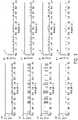
- FIG. 4 demonstrates the lasing spectra and time traces of the PCML laser in each of these configurations.
- a pulsewidth of 43 ns was used.
- 881 kHz a pulsewidth of 8.6 ns was used.
- the laser output spanned 80 nm at 80 GHz combline spacing.
- consistent performance was not achieved with pulsewidths below 8.6 ns.
- the number of output wavelengths was reduced by designing the waveforms to transmit every 4th combline. Note that these changes to laser performance required changes only to the AWG drive signals provided to the phase modulators; no hardware modifications were required. This enabled production of a CR-OCT source that was widely tunable and rapidly re-configurable.
- the laser output achieves a much higher combline extinction due to the laser cavity resonance.
- the laser output spectrum illustrated in FIG. 4(c) suggests a spectral extinction in excess of 25 dB.
- the instantaneous laser extinction may be higher.
- the PCML laser coherence length was measured by acquiring fringe signals as a function of sample arm mirror position (relative to the reference arm). The measurement was done for 176 kHz and 881 kHz configurations for the analysis of the relationship between the pulse width and the coherence length of the source. The point-spread functions were calculated for fringe signals at the same circular delay position within increasing orders. The axial resolution was measured from acquired point spread functions to be 17 ⁇ m, which was consistent with and without the booster SOA.
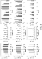
- the coherence length (6 dB roll-off) was 85 mm (mirror displacement) for pulsewidths of 43 ns (176 kHz A-line) and 8.6 ns (881 kHz A-line) ( FIG. 5 (a, c)).
- the coherence length was measured to be the same for both pulsewidths. It would not be anticipated that the coherence length would be affected by changing the sequence of output comblines at the same pulsewidth (e.g., 881 kHz and 3.52 MHz outputs), although this was not measured explicitly.
- the prototype laser output power was low (approximately 1 mW)
- the PCML coherence length was also tested with a booster SOA (outside of cavity).
- the booster SOA increased power to 50 mW and decreased the coherence length to 50 mm (100 mm CR-OCT imaging range), as shown in FIG. 5 (b, d). This reduction is a consequence of linewidth broadening in the SOA. It was also observed that the booster SOA increased the noise floor, which needs to be examined further.
- CR-OCT images were acquired at each of the three imaging speeds (176 kHz, 881 kHz, and 3.52 MHz). As expected, the circular depth/delay range for the 3.52 MHz image is different than that for 176 kHz and 881 kHz due to the generation of a 320 GHz frequency comb rather than an 80 GHz frequency comb.
- the laser was used with the booster SOA for imaging experiments.
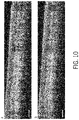
- FIG. 6 shows the acquired CR-OCT images of an IR detection card ( FIGS.
- FIGS. 6(d)-6(e) a finger
- FIGS. 6(d)-6(e) a finger
- the depths of the circular ranges were approximately 1.9 mm for 176 kHz and 881 kHz configurations and 0.48 mm for 3.52 MHz configuration. Note that the total imaging depth range and the circular delay range are distinct parameters; signals can be acquired over the total imaging range, which is limited by the source coherence, but appear within a compressed image equal to the circular delay range.
- Embodiments of a novel laser architecture have been demonstrated which provide stepped frequency comb outputs for moderate speed CR-OCT.
- the PCML laser design has several unique features. It was shown in the operation of the laser at 3.52 MHz that the PCML laser allows the user to set specific comblines, skip comblines, or modify the sequence of generated comblines. This was done through design of the drive waveforms, without hardware modification, and can be used to create highly re-configurable sources for CR-OCT.
- the speed of the PCML laser was not directly defined by the magnitude of the intra-cavity dispersion as is the case for SPML lasers.
- Certain embodiments of the invention provide procedures for reducing noise in the disclosed source.
- the disclosed PCML source may impose high relative intensity noise (RIN) that could limit its utility in practice.
- RIN relative intensity noise
- procedures that can make PCML highly stable by adjusting the driving waveform for the phase modulators (EOMs) to generate discrete pulses at each wavelength (with a "laser off' time between pulses) and with specific pulse durations (pulsewidths) that are related to the etalon Finesse used in the cavity ( FIG. 7 ).
- EOMs phase modulators
- the noise-reducing procedures can be carried out using systems such as those disclosed above (e.g. see FIG. 8(a) ).
- One modification of the system was to test several different etalons having similar FSRs and different Finesses for the noise analysis, where one of the etalons was selected for the final laser demonstration.
- the driving waveforms for the phase modulators were designed to include an "on" and "off' state for each pulse ( FIG. 7(a) ).
- the idea of having on and off states originated from the integration time (switch time) of the etalon, which is range of group delay transit times for light of different optical frequencies to pass through the etalon.
- This integration time is the inverse of the linewidth of each etalon combline.
- An optical pulse of duration less than the integration time will be temporally stretched when passed through the etalon, resulting in a pulse with duration that is approximately given by the integration time.
- By designing in an off time located between pulses and of sufficient duration one can avoid temporally overlapped pulses at the output of the etalon. Temporally overlapping pulses causes lasing instability and higher intensity noise. Based on this, it was determined that the optimal on/off times would be a function of etalon linewidth (which is a function of the Etalon Finesse and FSR).
- the chirped waveforms disclosed above were used to control the phase modulators. However, only one chirped waveform was used rather than multiple waveforms, in order to achieve stable lasing over the multiple cavity roundtrips.
- a uniform (non-chirped) sinusoidal waveform having different RF frequencies was used on each phase modulator ( FIG. 7(b) ).
- Optical pulses are generated during the waveforms associated with the on times at the selected wavelength determined by the waveform properties as described above. The waveforms associated with the off times suppress transmission of all comblines, and turns the laser off transiently.
- the pattern that was observed was that there was no lasing transitioning to stable lasing transitioning to unstable lasing as the laser on time/pulsewidth was increased, where the scale factor for these transitions depends on the etalon's Finesse.
- the optimal operating condition for laser on-time is approximately given by the inverse of the linewidth of each etalon comb-line, where the etalon linewidth is given by the etalon FSR divided by the Finesse.
- the optimal pulsewidth is therefore approximately given by the etalon Finesse divided by the etalon FSR.
- both pulses showed a significant amount of noise when the "laser off” time was too short, which means they are not well separated.
- the pulses became stable as in the previous experiment.
- the threshold of the "laser off” time for stable lasing also scales with the integration time of the etalon determined by the linewidth. It was also found that RIN is more consistent with higher Finesse, possibly because of the longer "laser on” time so that the signal from the AWG is capable of making more accurate and predictable extinctions.
- the ortho-RIN of each pulse was below 1 percent when measured with 2 GHz bandwidth detector and digitizer.
- the rest of the system including interferometry, detection part, and the imaging microscope was the same as the source disclosed above.
- the system sensitivity achieved was 104 dB with 35mW sample arm power, and the 6-dB roll-off depth was 74 mm. From the work disclosed above it can be assumed that the sensitivity roll-off of the PCML would be even longer without the booster SOA. Imaging of finger skin also showed a significant SNR increase for approximately 20 dB from the previous work.
- the laser can be configured for slower speeds by generating an effective long pulse at a given wavelength through repeating the same wavelength multiple times.
- a 5 ns pulse at 1550.00 nm can be repeated ten times, creating a pulse train that is 50 ns in duration comprising 10 individual pulses.
- the detection system can use low-pass analog filtering to convert this pulse train to a single 50 ns pulse. In this way, the laser speed can be reduced while optimal noise performance in maintained.
- the number of repeated pulses at each wavelength can be any integer, subject to the aforementioned constraint that the laser output sequence is equal to or is a harmonic of the cavity round trip time.
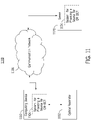
- a computing device 1110 can execute at least a portion of a system for providing a source for CR-OCT 1104 and provide control signals to one or more optical modulators associated with an optical resonator 1102. Additionally or alternatively, in some embodiments, computing device 1110 can communicate information regarding the control signals to or from a server 1120 over a communication network 1106, which can execute at least a portion of system for providing a source for CR-OCT 1104.
- server 1120 can return information to computing device 1110 (and/or any other suitable computing device) relating to the control signals for system for providing a source for CR-OCT 1104.
- This information may be transmitted and/or presented to a user (e.g. a researcher, an operator, a clinician, etc.) and/or may be stored (e.g. as part of a research database or a medical record associated with a subject).
- computing device 1110 and/or server 1120 can be any suitable computing device or combination of devices, such as a desktop computer, a laptop computer, a smartphone, a tablet computer, a wearable computer, a server computer, a virtual machine being executed by a physical computing device, etc.
- system for providing a source for CR-OCT 1104 can present information about the control signals to a user (e.g., researcher and/or physician).
- optical resonator 1102 may include optical components such as those disclosed herein (e.g. see FIG. 2(a) ).
- communication network 1106 can be any suitable communication network or combination of communication networks.
- communication network 1106 can include a Wi-Fi network (which can include one or more wireless routers, one or more switches, etc.), a peer-to-peer network (e.g., a Bluetooth network), a cellular network (e.g., a 3G network, a 4G network, etc., complying with any suitable standard, such as CDMA, GSM, LTE, LTE Advanced, WiMAX, etc.), a wired network, etc.
- Wi-Fi network which can include one or more wireless routers, one or more switches, etc.
- peer-to-peer network e.g., a Bluetooth network
- a cellular network e.g., a 3G network, a 4G network, etc., complying with any suitable standard, such as CDMA, GSM, LTE, LTE Advanced, WiMAX, etc.
- a wired network etc.
- communication network 1106 can be a local area network, a wide area network, a public network (e.g., the Internet), a private or semi-private network (e.g., a corporate or university intranet), any other suitable type of network, or any suitable combination of networks.
- Communications links shown in FIG. 11 can each be any suitable communications link or combination of communications links, such as wired links, fiber optic links, Wi-Fi links, Bluetooth links, cellular links, etc.
- FIG. 12 shows an example 1200 of hardware that can be used to implement computing device 1110 and server 1120 in accordance with some embodiments of the disclosed subject matter.
- computing device 1110 can include a processor 1202, a display 1204, one or more inputs 1206, one or more communication systems 1208, and/or memory 1210.
- processor 1202 can be any suitable hardware processor or combination of processors, such as a central processing unit, a graphics processing unit, etc.
- display 1204 can include any suitable display devices, such as a computer monitor, a touchscreen, a television, etc.
- inputs 1206 can include any suitable input devices and/or sensors that can be used to receive user input, such as a keyboard, a mouse, a touchscreen, a microphone, etc.
- communications systems 1208 can include any suitable hardware, firmware, and/or software for communicating information over communication network 1106 and/or any other suitable communication networks.
- communications systems 1208 can include one or more transceivers, one or more communication chips and/or chip sets, etc.
- communications systems 1208 can include hardware, firmware and/or software that can be used to establish a Wi-Fi connection, a Bluetooth connection, a cellular connection, an Ethernet connection, etc.
- memory 1210 can include any suitable storage device or devices that can be used to store instructions, values, etc., that can be used, for example, by processor 1202 to present content using display 1204, to communicate with server 1120 via communications system(s) 1208, etc.
- Memory 1210 can include any suitable volatile memory, non-volatile memory, storage, or any suitable combination thereof.
- memory 1210 can include RAM, ROM, EEPROM, one or more flash drives, one or more hard disks, one or more solid state drives, one or more optical drives, etc.
- memory 1210 can have encoded thereon a computer program for controlling operation of computing device 1110.
- processor 1202 can execute at least a portion of the computer program to present content (e.g., images, user interfaces, graphics, tables, etc.), receive content from server 1120, transmit information to server 1120, etc.
- server 1120 can include a processor 1212, a display 1214, one or more inputs 1216, one or more communications systems 1218, and/or memory 1220.
- processor 1212 can be any suitable hardware processor or combination of processors, such as a central processing unit, a graphics processing unit, etc.
- display 1214 can include any suitable display devices, such as a computer monitor, a touchscreen, a television, etc.
- inputs 1216 can include any suitable input devices and/or sensors that can be used to receive user input, such as a keyboard, a mouse, a touchscreen, a microphone, etc.
- communications systems 1218 can include any suitable hardware, firmware, and/or software for communicating information over communication network 1106 and/or any other suitable communication networks.
- communications systems 1218 can include one or more transceivers, one or more communication chips and/or chip sets, etc.
- communications systems 1218 can include hardware, firmware and/or software that can be used to establish a Wi-Fi connection, a Bluetooth connection, a cellular connection, an Ethernet connection, etc.
- memory 1220 can include any suitable storage device or devices that can be used to store instructions, values, etc., that can be used, for example, by processor 1212 to present content using display 1214, to communicate with one or more computing devices 1110, etc.
- Memory 1220 can include any suitable volatile memory, non-volatile memory, storage, or any suitable combination thereof.
- memory 1220 can include RAM, ROM, EEPROM, one or more flash drives, one or more hard disks, one or more solid state drives, one or more optical drives, etc.
- memory 1220 can have encoded thereon a server program for controlling operation of server 1120.
- processor 1212 can execute at least a portion of the server program to transmit information and/or content (e.g., results of a tissue identification and/or classification, a user interface, etc.) to one or more computing devices 1110, receive information and/or content from one or more computing devices 1110, receive instructions from one or more devices (e.g., a personal computer, a laptop computer, a tablet computer, a smartphone, etc.), etc.
- information and/or content e.g., results of a tissue identification and/or classification, a user interface, etc.
- processor 1212 can execute at least a portion of the server program to transmit information and/or content (e.g., results of a tissue identification and/or classification, a user interface, etc.) to one or more computing devices 1110, receive information and/or content from one or more computing devices 1110, receive instructions from one or more devices (e.g., a personal computer, a laptop computer, a tablet computer, a smartphone, etc.), etc.
- devices e.g
- any suitable computer readable media can be used for storing instructions for performing the functions and/or processes described herein.
- computer readable media can be transitory or non-transitory.
- non-transitory computer readable media can include media such as magnetic media (such as hard disks, floppy disks, etc.), optical media (such as compact discs, digital video discs, Blu-ray discs, etc.), semiconductor media (such as RAM, Flash memory, electrically programmable read only memory (EPROM), electrically erasable programmable read only memory (EEPROM), etc.), any suitable media that is not fleeting or devoid of any semblance of permanence during transmission, and/or any suitable tangible media.
- magnetic media such as hard disks, floppy disks, etc.
- optical media such as compact discs, digital video discs, Blu-ray discs, etc.
- semiconductor media such as RAM, Flash memory, electrically programmable read only memory (EPROM), electrically erasable programmable read only memory (EEPROM), etc.
- transitory computer readable media can include signals on networks, in wires, conductors, optical fibers, circuits, or any suitable media that is fleeting and devoid of any semblance of permanence during transmission, and/or any suitable intangible media.
- mechanism can encompass hardware, software, firmware, or any suitable combination thereof.
- FIG. 13 provides diagrams of interferometry systems that may be used in conjunction with various embodiments of the invention.
- FIG. 13 illustrates a Mach-Zehnder type interferometer that may be implemented using free space optics ( FIG. 13 , panel A) or a fiber arrangement ( FIG. 13 , panel B). Other interferometer types (e.g. Michelson) can also be applied.
- the light source LS in either panel A or panel B of FIG. 13 may be an embodiment of a PCML laser such as those disclosed herein.
- Beam B9, emitted from LS, is directed to the interferometer input where it is split into two paths of approximately equal length using a beam splitter (BS3).
- B10 is directed towards a sample S.
- BS3 beam splitter
- the backscattered light from the object of interest is then directed towards the interferometer output (B11).
- beam B12 is directed towards a phase modulator (PM).
- the beam after the PM i.e. beam B13
- the output beam B14 is then detected by a detector D (e.g. a photodiode).
- a fiber-based interferometer shown in FIG. 13 , panel B readily allows balanced detection due to a phase shift of ⁇ between output beams B14 and B15.
- the detected signal is digitized using data collection and processing system (which may include a data acquisition board or real time oscilloscope (DAQ)) at a sampling rate f S .
- DAQ real time oscilloscope
Landscapes
- Physics & Mathematics (AREA)
- Electromagnetism (AREA)
- Optics & Photonics (AREA)
- Engineering & Computer Science (AREA)
- Plasma & Fusion (AREA)
- General Physics & Mathematics (AREA)
- Nonlinear Science (AREA)
- Health & Medical Sciences (AREA)
- General Health & Medical Sciences (AREA)
- Nuclear Medicine, Radiotherapy & Molecular Imaging (AREA)
- Radiology & Medical Imaging (AREA)
- Lasers (AREA)
- Optical Modulation, Optical Deflection, Nonlinear Optics, Optical Demodulation, Optical Logic Elements (AREA)
- Investigating Or Analysing Materials By Optical Means (AREA)
Applications Claiming Priority (3)
| Application Number | Priority Date | Filing Date | Title |
|---|---|---|---|
| US202062968299P | 2020-01-31 | 2020-01-31 | |
| PCT/US2021/015753 WO2021194630A2 (en) | 2020-01-31 | 2021-01-29 | Frequency-comb generation based on electro-optic phase-code mode-locking for circular-ranging oct |
| EP21776191.5A EP4096509B1 (de) | 2020-01-31 | 2021-01-29 | Frequenzkammerzeugung basierend auf der basis einer elektrooptischen phasencode-modusverriegelung für oct mit kreisförmiger entfernungsmessung |
Related Parent Applications (2)
| Application Number | Title | Priority Date | Filing Date |
|---|---|---|---|
| EP21776191.5A Division-Into EP4096509B1 (de) | 2020-01-31 | 2021-01-29 | Frequenzkammerzeugung basierend auf der basis einer elektrooptischen phasencode-modusverriegelung für oct mit kreisförmiger entfernungsmessung |
| EP21776191.5A Division EP4096509B1 (de) | 2020-01-31 | 2021-01-29 | Frequenzkammerzeugung basierend auf der basis einer elektrooptischen phasencode-modusverriegelung für oct mit kreisförmiger entfernungsmessung |
Publications (1)
| Publication Number | Publication Date |
|---|---|
| EP4113206A1 true EP4113206A1 (de) | 2023-01-04 |
Family
ID=77892544
Family Applications (2)
| Application Number | Title | Priority Date | Filing Date |
|---|---|---|---|
| EP21776191.5A Active EP4096509B1 (de) | 2020-01-31 | 2021-01-29 | Frequenzkammerzeugung basierend auf der basis einer elektrooptischen phasencode-modusverriegelung für oct mit kreisförmiger entfernungsmessung |
| EP22191202.5A Pending EP4113206A1 (de) | 2020-01-31 | 2021-01-29 | Frequenzkammerzeugung basierend auf einer elektrooptischen phasen-code-modusverriegelung für zirkularreichweiten-oct |
Family Applications Before (1)
| Application Number | Title | Priority Date | Filing Date |
|---|---|---|---|
| EP21776191.5A Active EP4096509B1 (de) | 2020-01-31 | 2021-01-29 | Frequenzkammerzeugung basierend auf der basis einer elektrooptischen phasencode-modusverriegelung für oct mit kreisförmiger entfernungsmessung |
Country Status (7)
| Country | Link |
|---|---|
| US (1) | US12474157B2 (de) |
| EP (2) | EP4096509B1 (de) |
| JP (2) | JP7629463B2 (de) |
| CN (1) | CN115023179B (de) |
| AU (1) | AU2021241492B2 (de) |
| CA (1) | CA3162012A1 (de) |
| WO (1) | WO2021194630A2 (de) |
Families Citing this family (13)
| Publication number | Priority date | Publication date | Assignee | Title |
|---|---|---|---|---|
| US12431687B2 (en) * | 2021-09-22 | 2025-09-30 | Raytheon Company | Multi-octave spanning millimeter wave source with phase memory |
| JP2023099252A (ja) * | 2021-12-30 | 2023-07-12 | 株式会社三洋物産 | 遊技機 |
| JP2023099257A (ja) * | 2021-12-30 | 2023-07-12 | 株式会社三洋物産 | 遊技機 |
| CN114518170B (zh) * | 2022-01-28 | 2022-09-16 | 哈尔滨工业大学 | 一种无近似无迭代的腔内电光调制型光频梳光谱分析方法、设备及介质 |
| US11906875B2 (en) | 2022-07-25 | 2024-02-20 | Honeywell International Inc. | Systems, devices, and methods for optical frequency combs |
| CN115598650B (zh) * | 2022-09-15 | 2026-04-07 | 中南大学 | 一种重频自标定双光频梳测距系统及方法 |
| EP4351043A1 (de) * | 2022-10-05 | 2024-04-10 | Fundació Institut de Ciències Fotòniques | Optisches system zur phasenmodulation |
| US12019353B2 (en) | 2022-10-12 | 2024-06-25 | Honeywell International Inc. | System and method for generating optical frequency combs using an optical waveguide including chirped Bragg gratings |
| US11982922B1 (en) | 2022-11-14 | 2024-05-14 | Rockwell Collins, Inc. | Polarization maintaining parametric optical frequency comb generator |
| WO2024166554A1 (ja) * | 2023-02-09 | 2024-08-15 | 学校法人東邦大学 | レーザー共振器、光コム発生装置、及び光コム発生方法 |
| WO2024172753A1 (en) * | 2023-02-14 | 2024-08-22 | Compoundtek Pte. Ltd. | Silicon photonic device for gas monitoring |
| CN116609269B (zh) * | 2023-05-15 | 2025-08-08 | 上海交通大学 | 基于光子芯片的sd-oct系统 |
| CN117293634B (zh) * | 2023-09-26 | 2026-03-31 | 北京工业大学 | 一种双相位调制层相干阵激光器 |
Citations (10)
| Publication number | Priority date | Publication date | Assignee | Title |
|---|---|---|---|---|
| JP2009031238A (ja) * | 2007-06-29 | 2009-02-12 | Optical Comb Inc | 光コヒーレンストモグラフィー装置 |
| US20110155916A1 (en) * | 2008-05-13 | 2011-06-30 | Canon Kabushiki Kaisha | Laser apparatus, driving method of the same and optical tomographic imaging apparatus |
| US20110170110A1 (en) * | 2010-01-13 | 2011-07-14 | Canon Kabushiki Kaisha | Wavelength-tunable light source apparatus |
| WO2012018195A2 (ko) * | 2010-08-04 | 2012-02-09 | 부산대학교 산학협력단 | 능동형 모드 잠김 레이저를 이용한 광 결맞음 단층 영상기기 |
| JP2012080013A (ja) * | 2010-10-05 | 2012-04-19 | Canon Inc | 光源装置及びこれを用いた撮像装置 |
| US20120162662A1 (en) * | 2010-12-27 | 2012-06-28 | Axsun Technologies, Inc. | Actively Mode Locked Laser Swept Source for OCT Medical Imaging |
| US20170299697A1 (en) * | 2013-06-23 | 2017-10-19 | Eric Swanson | Light Detection and Ranging System with Photonic Integrated Circuit |
| US20190049232A1 (en) * | 2016-02-12 | 2019-02-14 | The General Hospital Corporation | Apparatus and methods for high-speed and long depth range imaging using optical coherence tomography |
| US20190082962A1 (en) * | 2013-07-26 | 2019-03-21 | The General Hospital Corporation | System, apparatus and method for utilizing optical dispersion for fourier-domain optical coherence tomography |
| US20190368859A1 (en) * | 2013-06-23 | 2019-12-05 | Eric Swanson | Wavelength Tunable Laser Device |
Family Cites Families (18)
| Publication number | Priority date | Publication date | Assignee | Title |
|---|---|---|---|---|
| JP4174182B2 (ja) * | 1999-01-26 | 2008-10-29 | カリフォルニア インスティチュート オブ テクノロジー | 光共振器を備えた光電子発振装置 |
| WO2002025783A2 (en) | 2000-09-22 | 2002-03-28 | Calmar Optcom, Inc. | Actively mode-locked fiber laser with controlled chirp output |
| US6522450B2 (en) * | 2001-04-25 | 2003-02-18 | Corning Incorporated | Loss-less tunable per-channel dispersion compensator |
| CN1623085A (zh) * | 2002-01-24 | 2005-06-01 | 通用医疗公司 | 使用光谱带并行检测的低相干干涉测量法(lci)和光学相干层析成像(oct)信号的测距和降噪的装置和方法 |
| GB0312295D0 (en) | 2003-05-30 | 2003-07-02 | Univ St Andrews | Frequency comb generator |
| JP4444689B2 (ja) * | 2004-02-26 | 2010-03-31 | 富士通株式会社 | 光通信用光装置 |
| JP4715710B2 (ja) | 2005-10-28 | 2011-07-06 | 株式会社日立製作所 | Rfidシステム,rfidケーブルシステム,rfidケーブル敷設方法 |
| US20070291277A1 (en) * | 2006-06-20 | 2007-12-20 | Everett Matthew J | Spectral domain optical coherence tomography system |
| WO2010031163A1 (en) * | 2008-09-17 | 2010-03-25 | Institut National De La Recherche Scientifique | Cross-chirped interferometry system and method for light detection and ranging |
| US8681827B2 (en) * | 2011-05-16 | 2014-03-25 | Oewaves, Inc. | Generation of single optical tone, RF oscillation signal and optical comb in a triple-oscillator device based on nonlinear optical resonator |
| JP6587615B2 (ja) * | 2014-01-24 | 2019-10-09 | カリフォルニア インスティチュート オブ テクノロジー | デュアル周波数光源 |
| JP2017528925A (ja) * | 2014-09-22 | 2017-09-28 | イムラ アメリカ インコーポレイテッド | 低キャリア位相ノイズファイバ発振器 |
| DE102014226973B4 (de) * | 2014-12-23 | 2021-03-18 | Menlo Systems Gmbh | Optische Resonatoranordnung und Verfahren zum Einstellen einer Umlaufzeit in einem Resonator |
| WO2018113893A1 (en) * | 2016-12-19 | 2018-06-28 | Csem Centre Suisse D'electronique Et De Microtechnique S.A. | Laser source apparatus and method for generating temporal dissipative cavity solitons |
| EP3361583B1 (de) * | 2017-02-13 | 2019-12-11 | Max-Planck-Gesellschaft zur Förderung der Wissenschaften e.V. | Erzeugung von laserpulsen und spektroskopie mittels des zeitlichen talboteffekts und zugehörige vorrichtungen |
| FR3064078B1 (fr) | 2017-03-17 | 2020-07-24 | Commissariat Energie Atomique | Dispositif optoelectronique de generation d’un peigne de frequences |
| WO2018218031A1 (en) * | 2017-05-24 | 2018-11-29 | Massachusetts Institute Of Technology | Short-pulse wavelength tuning via timed soliton-dispersive wave interaction |
| WO2019213137A1 (en) * | 2018-04-30 | 2019-11-07 | President And Fellows Of Harvard College | Optical frequency comb generation in integrated lithium niobate devices |
-
2021
- 2021-01-29 EP EP21776191.5A patent/EP4096509B1/de active Active
- 2021-01-29 US US17/759,735 patent/US12474157B2/en active Active
- 2021-01-29 AU AU2021241492A patent/AU2021241492B2/en active Active
- 2021-01-29 CA CA3162012A patent/CA3162012A1/en active Pending
- 2021-01-29 EP EP22191202.5A patent/EP4113206A1/de active Pending
- 2021-01-29 JP JP2022541662A patent/JP7629463B2/ja active Active
- 2021-01-29 CN CN202180011957.4A patent/CN115023179B/zh active Active
- 2021-01-29 WO PCT/US2021/015753 patent/WO2021194630A2/en not_active Ceased
-
2025
- 2025-01-30 JP JP2025014044A patent/JP7755092B2/ja active Active
Patent Citations (10)
| Publication number | Priority date | Publication date | Assignee | Title |
|---|---|---|---|---|
| JP2009031238A (ja) * | 2007-06-29 | 2009-02-12 | Optical Comb Inc | 光コヒーレンストモグラフィー装置 |
| US20110155916A1 (en) * | 2008-05-13 | 2011-06-30 | Canon Kabushiki Kaisha | Laser apparatus, driving method of the same and optical tomographic imaging apparatus |
| US20110170110A1 (en) * | 2010-01-13 | 2011-07-14 | Canon Kabushiki Kaisha | Wavelength-tunable light source apparatus |
| WO2012018195A2 (ko) * | 2010-08-04 | 2012-02-09 | 부산대학교 산학협력단 | 능동형 모드 잠김 레이저를 이용한 광 결맞음 단층 영상기기 |
| JP2012080013A (ja) * | 2010-10-05 | 2012-04-19 | Canon Inc | 光源装置及びこれを用いた撮像装置 |
| US20120162662A1 (en) * | 2010-12-27 | 2012-06-28 | Axsun Technologies, Inc. | Actively Mode Locked Laser Swept Source for OCT Medical Imaging |
| US20170299697A1 (en) * | 2013-06-23 | 2017-10-19 | Eric Swanson | Light Detection and Ranging System with Photonic Integrated Circuit |
| US20190368859A1 (en) * | 2013-06-23 | 2019-12-05 | Eric Swanson | Wavelength Tunable Laser Device |
| US20190082962A1 (en) * | 2013-07-26 | 2019-03-21 | The General Hospital Corporation | System, apparatus and method for utilizing optical dispersion for fourier-domain optical coherence tomography |
| US20190049232A1 (en) * | 2016-02-12 | 2019-02-14 | The General Hospital Corporation | Apparatus and methods for high-speed and long depth range imaging using optical coherence tomography |
Non-Patent Citations (1)
| Title |
|---|
| SIDDIQUI ET AL.: "Compensation of spectral and rf errors in swept-source OCT for high extinction complex demodulation", OPTICS EXPRESS, vol. 23, no. 5, 2015, pages 5508 - 5520 |
Also Published As
| Publication number | Publication date |
|---|---|
| EP4096509B1 (de) | 2026-03-25 |
| JP7629463B2 (ja) | 2025-02-13 |
| JP2023512154A (ja) | 2023-03-24 |
| CN115023179B (zh) | 2025-08-26 |
| JP2025069287A (ja) | 2025-04-30 |
| AU2021241492A1 (en) | 2022-06-02 |
| WO2021194630A2 (en) | 2021-09-30 |
| US20230332879A1 (en) | 2023-10-19 |
| CN115023179A (zh) | 2022-09-06 |
| US12474157B2 (en) | 2025-11-18 |
| AU2021241492B2 (en) | 2025-12-04 |
| EP4096509A2 (de) | 2022-12-07 |
| CA3162012A1 (en) | 2021-09-30 |
| JP7755092B2 (ja) | 2025-10-15 |
| WO2021194630A3 (en) | 2022-01-13 |
| WO2021194630A9 (en) | 2021-12-02 |
| EP4096509A4 (de) | 2024-02-21 |
Similar Documents
| Publication | Publication Date | Title |
|---|---|---|
| EP4096509B1 (de) | Frequenzkammerzeugung basierend auf der basis einer elektrooptischen phasencode-modusverriegelung für oct mit kreisförmiger entfernungsmessung | |
| US10966613B2 (en) | System, apparatus and method for utilizing optical dispersion for fourier-domain optical coherence tomography | |
| JP5495506B2 (ja) | レーザ装置および光断層画像撮像装置 | |
| JP5361243B2 (ja) | 光断層画像撮像装置 | |
| JP6298471B2 (ja) | 位相感知の干渉信号サンプリングを用いるoctシステム | |
| JP7314250B2 (ja) | サブサンプリング/円形測距光コヒーレンストモグラフィーのためのアクティブ直交復調 | |
| Lippok et al. | Extended coherence length and depth ranging using a Fourier-domain mode-locked frequency comb and circular interferometric ranging | |
| JP6071203B2 (ja) | 光源装置及びこれを用いた光干渉断層撮像装置、及び光発振方法 | |
| JP2022554271A (ja) | 円形測距光コヒーレンストモグラフィーにおける絶対深度の解像 | |
| Davila-Rodriguez et al. | Multiheterodyne detection for spectral compression and downconversion of arbitrary periodic optical signals | |
| Harper et al. | Phase-Code Mode-Locked Laser at 1060 nm for Circular-Ranging Optical Coherence Tomography | |
| US20140307752A1 (en) | Apparatus and method which can include center-wavelength selectable, bandwidth adjustable, spectrum customizable, and/or multiplexable swept-source laser arrangement | |
| Butler | Real-time characterisation of dynamic laser fields | |
| Mei et al. | 1?? μm wavelength swept fiber laser based on dispersion-tuning technique | |
| Huang et al. | 2.5 MHz highly coherent swept source for long-range tomographic detection | |
| Kuznetsov | SNR of swept SLEDs and swept lasers for OCT | |
| Chen et al. | High-speed wide tuning range wavelength swept laser around 1310 nm for frequency domain OCT |
Legal Events
| Date | Code | Title | Description |
|---|---|---|---|
| PUAI | Public reference made under article 153(3) epc to a published international application that has entered the european phase |
Free format text: ORIGINAL CODE: 0009012 |
|
| STAA | Information on the status of an ep patent application or granted ep patent |
Free format text: STATUS: THE APPLICATION HAS BEEN PUBLISHED |
|
| AC | Divisional application: reference to earlier application |
Ref document number: 4096509 Country of ref document: EP Kind code of ref document: P |
|
| AK | Designated contracting states |
Kind code of ref document: A1 Designated state(s): AL AT BE BG CH CY CZ DE DK EE ES FI FR GB GR HR HU IE IS IT LI LT LU LV MC MK MT NL NO PL PT RO RS SE SI SK SM TR |
|
| STAA | Information on the status of an ep patent application or granted ep patent |
Free format text: STATUS: REQUEST FOR EXAMINATION WAS MADE |
|
| P01 | Opt-out of the competence of the unified patent court (upc) registered |
Effective date: 20230526 |
|
| 17P | Request for examination filed |
Effective date: 20230614 |
|
| RBV | Designated contracting states (corrected) |
Designated state(s): AL AT BE BG CH CY CZ DE DK EE ES FI FR GB GR HR HU IE IS IT LI LT LU LV MC MK MT NL NO PL PT RO RS SE SI SK SM TR |
|
| STAA | Information on the status of an ep patent application or granted ep patent |
Free format text: STATUS: EXAMINATION IS IN PROGRESS |
|
| 17Q | First examination report despatched |
Effective date: 20240912 |