EP4113468B1 - Dispositif d'alimentation et procédé d'alimentation d'une pile de documents de valeur vers un dispositif de séparation, module de séparation et système de traitement de documents de valeur - Google Patents
Dispositif d'alimentation et procédé d'alimentation d'une pile de documents de valeur vers un dispositif de séparation, module de séparation et système de traitement de documents de valeur Download PDFInfo
- Publication number
- EP4113468B1 EP4113468B1 EP21020336.0A EP21020336A EP4113468B1 EP 4113468 B1 EP4113468 B1 EP 4113468B1 EP 21020336 A EP21020336 A EP 21020336A EP 4113468 B1 EP4113468 B1 EP 4113468B1
- Authority
- EP
- European Patent Office
- Prior art keywords
- stack
- lateral guide
- singler
- value documents
- elements
- Prior art date
- Legal status (The legal status is an assumption and is not a legal conclusion. Google has not performed a legal analysis and makes no representation as to the accuracy of the status listed.)
- Active
Links
Images


Classifications
-
- G—PHYSICS
- G07—CHECKING-DEVICES
- G07D—HANDLING OF COINS OR VALUABLE PAPERS, e.g. TESTING, SORTING BY DENOMINATIONS, COUNTING, DISPENSING, CHANGING OR DEPOSITING
- G07D11/00—Devices accepting coins; Devices accepting, dispensing, sorting or counting valuable papers
- G07D11/10—Mechanical details
- G07D11/16—Handling of valuable papers
-
- B—PERFORMING OPERATIONS; TRANSPORTING
- B65—CONVEYING; PACKING; STORING; HANDLING THIN OR FILAMENTARY MATERIAL
- B65H—HANDLING THIN OR FILAMENTARY MATERIAL, e.g. SHEETS, WEBS, CABLES
- B65H1/00—Supports or magazines for piles from which articles are to be separated
- B65H1/04—Supports or magazines for piles from which articles are to be separated adapted to support articles substantially horizontally, e.g. for separation from top of pile
- B65H1/06—Supports or magazines for piles from which articles are to be separated adapted to support articles substantially horizontally, e.g. for separation from top of pile for separation from bottom of pile
-
- B—PERFORMING OPERATIONS; TRANSPORTING
- B65—CONVEYING; PACKING; STORING; HANDLING THIN OR FILAMENTARY MATERIAL
- B65H—HANDLING THIN OR FILAMENTARY MATERIAL, e.g. SHEETS, WEBS, CABLES
- B65H3/00—Separating articles from piles
- B65H3/02—Separating articles from piles using friction forces between articles and separator
- B65H3/04—Endless-belt separators
- B65H3/042—Endless-belt separators separating from the bottom of the pile
-
- G—PHYSICS
- G07—CHECKING-DEVICES
- G07D—HANDLING OF COINS OR VALUABLE PAPERS, e.g. TESTING, SORTING BY DENOMINATIONS, COUNTING, DISPENSING, CHANGING OR DEPOSITING
- G07D11/00—Devices accepting coins; Devices accepting, dispensing, sorting or counting valuable papers
- G07D11/20—Controlling or monitoring the operation of devices; Data handling
- G07D11/24—Managing the inventory of valuable papers
-
- G—PHYSICS
- G07—CHECKING-DEVICES
- G07D—HANDLING OF COINS OR VALUABLE PAPERS, e.g. TESTING, SORTING BY DENOMINATIONS, COUNTING, DISPENSING, CHANGING OR DEPOSITING
- G07D11/00—Devices accepting coins; Devices accepting, dispensing, sorting or counting valuable papers
- G07D11/50—Sorting or counting valuable papers
-
- B—PERFORMING OPERATIONS; TRANSPORTING
- B65—CONVEYING; PACKING; STORING; HANDLING THIN OR FILAMENTARY MATERIAL
- B65H—HANDLING THIN OR FILAMENTARY MATERIAL, e.g. SHEETS, WEBS, CABLES
- B65H2402/00—Constructional details of the handling apparatus
- B65H2402/30—Supports; Subassemblies; Mountings thereof
- B65H2402/32—Sliding support means
-
- B—PERFORMING OPERATIONS; TRANSPORTING
- B65—CONVEYING; PACKING; STORING; HANDLING THIN OR FILAMENTARY MATERIAL
- B65H—HANDLING THIN OR FILAMENTARY MATERIAL, e.g. SHEETS, WEBS, CABLES
- B65H2402/00—Constructional details of the handling apparatus
- B65H2402/50—Machine elements
- B65H2402/53—Guideways
-
- B—PERFORMING OPERATIONS; TRANSPORTING
- B65—CONVEYING; PACKING; STORING; HANDLING THIN OR FILAMENTARY MATERIAL
- B65H—HANDLING THIN OR FILAMENTARY MATERIAL, e.g. SHEETS, WEBS, CABLES
- B65H2403/00—Power transmission; Driving means
- B65H2403/40—Toothed gearings
- B65H2403/41—Rack-and-pinion, cogwheel in cog railway
- B65H2403/411—Double rack cooperating with one pinion, e.g. for performing symmetrical displacement relative to pinion
-
- B—PERFORMING OPERATIONS; TRANSPORTING
- B65—CONVEYING; PACKING; STORING; HANDLING THIN OR FILAMENTARY MATERIAL
- B65H—HANDLING THIN OR FILAMENTARY MATERIAL, e.g. SHEETS, WEBS, CABLES
- B65H2511/00—Dimensions; Position; Numbers; Identification; Occurrences
- B65H2511/10—Size; Dimensions
- B65H2511/12—Width
-
- B—PERFORMING OPERATIONS; TRANSPORTING
- B65—CONVEYING; PACKING; STORING; HANDLING THIN OR FILAMENTARY MATERIAL
- B65H—HANDLING THIN OR FILAMENTARY MATERIAL, e.g. SHEETS, WEBS, CABLES
- B65H2511/00—Dimensions; Position; Numbers; Identification; Occurrences
- B65H2511/20—Location in space
- B65H2511/22—Distance
-
- B—PERFORMING OPERATIONS; TRANSPORTING
- B65—CONVEYING; PACKING; STORING; HANDLING THIN OR FILAMENTARY MATERIAL
- B65H—HANDLING THIN OR FILAMENTARY MATERIAL, e.g. SHEETS, WEBS, CABLES
- B65H2701/00—Handled material; Storage means
- B65H2701/10—Handled articles or webs
- B65H2701/19—Specific article or web
- B65H2701/1912—Banknotes, bills and cheques or the like
Definitions
- the invention relates to a feeder device and method for feeding a stack of value documents, in particular banknotes, to a singler device, a singler module and a system for processing value documents, in particular banknotes.
- Systems for banknote processing usually comprise a feeder device, which is configured to receive a stack of banknotes and to feed and/or guide same towards a singler device, which is configured to separate individual banknotes from the stack, wherein usually the lowermost banknote of the stack is drawn from the stack.
- the individual banknotes are then conveyed towards one or more processing modules, which are configured to process, in particular to count and/or examine and/or sort, the banknotes.
- WO2008139125 A2 discloses a document handling apparatus for sorting, counting, authenticating or otherwise handling documents such as banknotes.
- US2008018045 A1 discloses a paper feed cassette of an image forming device such as a facsimile machine and a copier.
- EP1288014 A2 relates to a sheet aligning operation performed when a sheet is treated, e.g., in the field of copying machines, printers and facsimile apparatuses.
- the object is achieved by a feeder device and method according to the independent claims, a singler module comprising such a feeder device and a system for processing value documents comprising such a singler module.
- a feeder device for feeding a stack of value documents, in particular banknotes, to a singler device, according to claim 1.
- a singler module comprises a singler device, which is configured to withdraw individual value documents from a stack of value documents, in particular banknotes, and a feeder device according to the first aspect for feeding the stack of value documents to the singler device.
- a system for processing value documents, in particular banknotes comprises one or more processing modules configured to process, in particular to transport and/or count and/or examine and/or sort, the value documents and at least one singler module according to the second aspect.
- aspects of present disclosure are preferably based on the approach of movably mounting the first and second lateral guide element on the stop element via first and second support elements, respectively, which are coupled with each other such that the first and second lateral guide element can only move simultaneously and in opposite directions (which can also be referred to as "counter movement"), and additionally providing, for each lateral guide element, at least one alignment bearing, which is configured to guide the respective lateral guide element on the stop element in a direction parallel to the direction of movement of the lateral guide elements.
- Such an imbalance of forces may occur, for example, if the first and/or second lateral guide element is manually shifted by touching the respective lateral guide element and/or applying a manual force to a section of the lateral guide element which is not located in the middle between first and second support elements, respectively.
- the alignment bearings ensure, or at least contribute, that during the adjustment of the width of the lateral guide elements forces on the first and/or second support elements are, preferably equilaterally or equally, distributed between the first and second support elements, respectively.
- present disclosure provides a feeder device and method, singler module and system for improved handling, robustness and stability.
- the first alignment bearing comprises one or more first rollers, which are rotatably mounted on the first lateral guide element and guided in a first guide rail provided at the stop element
- the second alignment bearing comprises one or more second rollers, which are rotatably mounted on the second lateral guide element and guided in a second guide rail provided at the stop element.
- the first and/or second guide rail is given by an elongated aperture, in particular a slot, provided in the stop element.
- the first and/or second guide rail is provided at the back side of the stop element. In both cases, guide rails for reliably guiding of the first and/or second rollers are obtained in a simple way.
- the feeder device comprises at least two first support elements and at least two second support elements.
- first alignment bearing is positioned between the first support elements, on which the first lateral guide element is mounted, and/or the second alignment bearing, on which the second lateral guide element is mounted, is positioned between the second support elements.
- first alignment bearing is positioned approximately in the middle between the first support elements and/or the second alignment bearing is positioned approximately in the middle between the second support elements. In this way, guiding of the first and/or second lateral guide element, respectively, and distributing of forces between the support elements is further improved.
- the first support element in particular a respective one of the first support elements, is positioned relative to the second support element, in particular a respective one of the second support elements, in such a way that toothed racks provided on the respective first and respective second support elements are positioned opposite each other
- the feeder device further comprises at least one gear wheel which is rotatably mounted on the stop element and engages with the toothed racks provided on the respective first and respective second support elements so as to couple the support elements with each other.
- the first alignment bearing is positioned at around the middle between the lower and upper ends of the first lateral guide element and/or the second alignment bearing is positioned at around the middle between the lower and upper ends of the second lateral guide element.
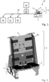
- Figure 1 shows a schematic representation of an example of a system for processing value documents, in particular banknotes.
- the system comprises a singler module 10 which is configured to receive at least one stack 1 of value documents, in particular banknotes, and to separate individual value documents from the stack 1.
- the singler module 10 comprises a feeder device 6 having a lower support surface 2 supporting the received stack 1 from below, at least one stop element 3 serving as a stop and guide for a rear side of the stack 1, and two lateral guide elements 4 provided at the front side of the stop element 3 and configured to guide the stack 1 at two lateral sides of the stack 1.
- the edges of value documents at the rear side of the stack 1 - also referred to as "lead edges" of the value documents - abut on the stop element 3.
- the lower support surface 2 is slightly inclined against the horizontal direction
- the stop element 3 is slightly inclined against the vertical direction. This facilitates slipping of the received stack 1 towards the stop element 3 due to gravitation to ensure that the lead edges of the value documents abut on the stop element 3.
- the singler module 10 further comprises a singler device 5 for separating or removing individual value documents from the stack 1.
- the singler device 5 is configured to separate the respectively lowermost value document from the stack 1.
- the singler device 5 may comprise one or more rollers and/or conveyor belts interacting such that the respectively lowermost value document is separated from the stack 1.
- each individual value document is conveyed along a transport path 20 to one or more sensor units 30 which are configured to detect physical properties of the value document and to generate according sensor signals, based on which a control unit 40 controls a subsequent processing of the value document, e.g. ejection into a stacker compartment 50, 51 or destruction in a shredder 52.
- FIG 2 shows a perspective front view of an example of a singler module comprising a singler device 5 and a feeder device 6, wherein the feeder device 6 comprises a lower support surface 2 for supporting a stack of value documents (not shown, see Figure 1 ) from below, a stop element 3 having a preferably plate-shaped structure and serving as a stop and guide for a rear side of the stack resting on the support surface 2, and two lateral guide elements 4a, 4b provided at the front side of the stop element 3 and serving as lateral guides for opposing lateral sides of the stack.
- the feeder device 6 comprises a lower support surface 2 for supporting a stack of value documents (not shown, see Figure 1 ) from below, a stop element 3 having a preferably plate-shaped structure and serving as a stop and guide for a rear side of the stack resting on the support surface 2, and two lateral guide elements 4a, 4b provided at the front side of the stop element 3 and serving as lateral guides for opposing lateral sides of the stack.
- the lateral guide elements 4a, 4b are preferably designed as guide flaps or plates and are movably mounted on the stop element 3 so as to allow the lateral guide elements 4a, 4b to be moved and/or shifted in a direction (see double arrows) parallel to the plane of the stop element 3 and/or the lower support surface 2.
- the lateral guide elements 4a, 4b are, preferably fixedly, mounted on support elements (not shown), which are movably mounted on the back side of the stop element 3.
- alignment bearings 8a, 8b are provided, which are configured to guide the lateral guide elements 4a, 4b in a direction parallel to the movement direction (see double arrows) of the lateral guide elements 4a, 4b. This will be elucidated in more detail in the following.
- Figure 3 shows an example of a feeder device 6 in a front view.
- the first and second lateral guide element 4a, 4b is provided with two first and second mounting brackets 14a, 14b, respectively, which extend through an elongated first and second aperture 14a', 14b', respectively, in the stop element 3.
- one of the first and second mounting brackets 14a, 14b is provided in an upper region of the respective lateral guide element 4a, 4b, whereas the other first and second mounting bracket 14a, 14b is provided in a lower region of the respective lateral guide element 4a, 4b.
- each of the first and second lateral guide element 4a, 4b comprises a guiding plate 15a, 15b, which is essentially perpendicular to the lateral guide elements 4a, 4b.
- the guiding plate 15a, 15b is essentially parallel to the direction of movement of the lateral guide elements 4a, 4b (see double arrows 100).
- each guiding plate 15a, 15b two first rollers 9a and two second rollers 9b, respectively, are mounted.
- the first and second rollers 9a, 9b are guided in and/or through a slot 11a, 11b, provided in the stop element 3.
- the first and second rollers 9a, 9b can be guided in a first and second guide rail (not shown, for details see description below with respect to Figure 4 ), respectively, provided on the back side of the stop element 3.
- the rollers 9a, 9b together with the slots 11a, 11b and the optional guide rails on the back side of the stop element 3 form a first and second alignment bearing 8a, 8b, respectively, in the sense of present disclosure, by which adverse effects resulting from a possible imbalance of forces acting on the first lateral guide element 4a and/or the second lateral guide element 4b are reduced or can even be avoided.
- Such an imbalance of forces may occur, for example, if the first and/or second lateral guide element 4a, 4b is manually shifted by touching the respective lateral guide element 4a, 4b and/or applying a manual force to a section of the lateral guide element 4a, 4b which is not located in the middle between the first or second mounting brackets 14a, 14b, respectively.
- the alignment bearings 8a, 8b help to, preferably equally, distribute forces occurring at the first and/or second mounting brackets 14a, 14b and/or at first and/or second support elements (not shown, for details see description below with respect to Figure 4 ), by which the lateral guide elements 4a, 4b are movably mounted on the back side of the stop element 3, between the first and/or second mounting brackets 14a, 14b and/or support elements, respectively.
- the alignment bearings 8a, 8b are positioned approximately in the middle between the lower and upper ends of the lateral guide elements 4a, 4b, respectively.
- Figure 4 shows an example of a feeder device 6 in a rear view.
- the first and second mounting brackets 14a, 14b are mounted, for example by means of screws or bolts, on first and second support elements 7a, 7b, respectively, which are movably mounted on the back side of the stop element 3.
- the first and second support elements 7a, 7b have an elongated shape and extend essentially parallel to the movement direction (see double arrows) of the lateral guide elements.
- a respective one of the first support elements 7a is coupled with a respective one of the second support elements 7b by means of toothed racks 13a, 13b provided at the first and second support element 7a, 7b, respectively, and a gear wheel 16 engaging with the respectively opposing toothed racks 13a, 13b, respectively.
- the first and second support elements 7a, 7b are coupled with each other such that the first and second lateral guide element 4a, 4b (see Figure 3 ) can only move simultaneously and in opposite directions (also referred to as "counter movement").
- this allows the width between the first and second lateral guide element to be adjusted by manually moving only one of the lateral guide elements 4a, 4b.
- first and second rollers 9a, 9b which are provided on guiding plates 15a, 15b of the lateral guiding elements 4a, 4b (see Figure 3 ) and guided in and/or through slots 11a, 11b, are guided in guide rails 12a, 12b provided on the back side of the support element 3.
- the feeder device 6 disclosed herein is very robust and yet smooth-running, so that the lateral guide elements 4a, 4b can be moved easily and safely, in particular without the danger of breaking during manual adjustment by a user, while not moving automatically or uncontrollably or unguided from their respectively set positions due to vibrations of the processing system.
- Biased feeding is opposed to centered feeding and means processing banknotes shifted from centered position regarding the banknote path, i.e., to the right or to the left from the middle.
- the banknote guides of the feeder device i.e., the lateral guide elements 4, are enabled to be aligned independently.
- the lateral guide elements 4a, 4b are positioned symmetrically with respect to the middle or center of the banknote path and are coupled with a coupling element or the toothed racks 13a, 13b via the support elements 7a, 7b. This enables the lateral guide elements 4a, 4b to be moved or adjusted synchronously in opposite directions while remaining symmetric with respect to the middle of the banknote path. This is particularly the arrangement used for centered feeding.
- a decouple element e.g., a knob or any other appropriate mean
- a decouple element is operated to disengage or decouple the support elements 7a, 7b with moving the coupling element or the toothed racks 13a, 13b into disengaged position.
- This enables the guide elements 4a, 4b to be moved independently in any of the directions shown with the double arrows 100 in Figure 2 , to any extent.
- the guide elements 4a, 4b are adjusted or moved preferably separately to the positions needed for biased feeding.
- a distance between the lateral guide elements 4a, 4b is preferably slightly bigger than the length of a processed banknote (measured across banknote path).
- the central axis of the banknote path is shifted to the left or to the right from the middle or center of the banknote path.
- the knob or another mean is operated to engage or couple the support elements 7a,7b and to move the coupling element or the toothed racks 13a, 13b back into engaged position.
- This enables the lateral guide elements 4a, 4b to be moved synchronously in opposite directions while remaining symmetric with respect to the point which is shifted from the middle of banknote path. This is the preferred arrangement used for biased feeding.
- the knob or another mean is operated to disengage or decouple the support elements 7a, 7b and to move the coupling element or the toothed racks 13a, 13b into disengaged position.
- the lateral guide elements 4a, 4b are moved separately to the respective extreme positions within the extent allowed by the alignment bearing 8a, 8b. Either both to the middle or right guide to the right side and left guide to the left side. This brings the lateral guide elements 4a, 4b into positions symmetric with respect to the middle or center of the banknote path.
- the knob or another mean is operated to engage or couple the support elements 7a, 7b and to move the coupling element or the toothed racks 13a, 13b back into engaged position. This enables the lateral guide elements 4a, 4b to be moved or adjusted, particularly only, synchronously in opposite directions while remaining symmetric with respect to the middle of the banknote path.
- the lateral guide elements 4a, 4b are adjusted to the positions needed for centered feeding.
- the distance between the lateral guide elements 4a, 4b is preferably slightly bigger than the length of processed banknote (measured across banknote path).
- the position of the banknote path is symmetric with respect to the middle or center of the banknote path.
- This adjustment can be done by moving, e.g., by hand, only one of the two lateral guide elements 4a, 4b because the second one will preferably move automatically due to coupling between the support elements 7a, 7b.
Landscapes
- Physics & Mathematics (AREA)
- General Physics & Mathematics (AREA)
- Engineering & Computer Science (AREA)
- Mechanical Engineering (AREA)
- Sheets, Magazines, And Separation Thereof (AREA)
Claims (8)
- Dispositif d'alimentation (6) destiné à alimenter une pile (1) de documents de valeur, en particulier des billets de banque, vers un dispositif de séparation (5), qui est conçu pour retirer des documents de valeur individuels de la pile (1), le dispositif d'alimentation (6) comprenant :- un élément de butée (3) ayant un côté avant et un côté arrière, le côté avant étant conçu pour servir de butée à un côté arrière de la pile (1) et pour guider la pile (1) au niveau du côté arrière de la pile vers le dispositif de séparation (5),- un premier et un second élément de guidage latéral (4a, 4b) situés au niveau du côté avant de l'élément de butée (3) et conçus pour guider la pile (1) au niveau de deux côtés latéraux de la pile (1) vers le dispositif de séparation (5),- au moins un premier élément de support (7a), sur lequel est monté le premier élément de guidage latéral (4a), et au moins un deuxième élément de support (7b), sur lequel est monté le second élément de guidage latéral (4b), le premier et le deuxième élément de support (7a, 7b) étant montés mobiles sur l'élément de butée (3) et le premier élément de support (7a) étant accouplé au deuxième élément de support (7b) de sorte qu'en déplaçant l'un des éléments de guidage latéraux (4a, 4b) dans une première direction, l'autre élément de guidage latéral (4b, 4a) soit déplacé dans une seconde direction opposée à la première direction, et- au moins un premier palier d'alignement (8a) conçu pour guider le premier élément de guidage latéral (4a) sur l'élément de butée (3) dans la première et la seconde direction, et au moins un second palier d'alignement (8b) conçu pour guider le second élément de guidage latéral (4b) sur l'élément de butée (3) dans la première et la seconde direction, le premier palier d'alignement (8a) comprenant un ou plusieurs premiers rouleaux (9a), qui sont montés rotatifs sur le premier élément de guidage latéral (4a) et guidés dans un premier rail de guidage (11a, 12a) situé au niveau de l'élément de butée (3) et/ou le second palier d'alignement (8b) comprenant un ou plusieurs seconds rouleaux (9b), qui sont montés rotatifs sur le second élément de guidage latéral (4b) et guidés dans un second rail de guidage (11b, 12b) situé au niveau de l'élément de butée (3).
- Dispositif d'alimentation (6) selon la revendication 1, le premier et/ou le second rail de guidage (11a, 11b) étant donné par une ouverture allongée, en particulier une fente, située dans l'élément de butée (3).
- Dispositif d'alimentation (6) selon la revendication 1, le premier et/ou le second rail de guidage (12a, 12b) étant situé au niveau du côté arrière de l'élément de butée.
- Dispositif d'alimentation (6) selon l'une quelconque des revendications précédentes, le dispositif d'alimentation (6) comprenant au moins deux premiers éléments de support (7a) et au moins deux deuxièmes éléments de support (7b), le premier palier d'alignement (8a) étant positionné entre les premiers éléments de support (7a) et/ou le second palier d'alignement (8b) étant positionné entre les deuxièmes éléments de support (7b).
- Dispositif d'alimentation (6) selon l'une quelconque des revendications précédentes, le premier élément de support (7a) étant positionné par rapport au deuxième élément de support (7b) de sorte que les crémaillères (13a, 13b) situées sur le premier et le deuxième élément de support (7a, 7b) respectif soient positionnées à l'opposé l'une de l'autre, et le dispositif d'alimentation (6) comprenant en outre au moins une roue dentée (16) qui est montée rotative sur l'élément de butée (3) et vient en prise avec les crémaillères (13a, 13b) situées sur le premier et le deuxième élément de support (7a, 7b) de sorte à accoupler les éléments de support (7a, 7b) l'un à l'autre.
- Module de séparation (10) comprenant un dispositif de séparation (5), qui est conçu pour retirer des documents de valeur individuels d'une pile (1) de documents de valeur, en particulier des billets de banque, et un dispositif d'alimentation (6) selon l'une quelconque des revendications précédentes pour alimenter la pile (1) de documents de valeur vers le dispositif de séparation (5).
- Système de traitement de documents de valeur, en particulier des billets de banque, comprenant un ou plusieurs modules de traitement (20, 30, 40, 50 - 52) conçus pour traiter, en particulier transporter et/ou compter et/ou examiner et/ou trier, les documents de valeur et au moins un module de séparation (10) selon la revendication précédente.
- Procédé d'alimentation d'une pile (1) de documents de valeur, en particulier des billets de banque, vers un dispositif de séparation (5), qui est conçu pour retirer des documents de valeur individuels de la pile (1), le procédé utilisant un dispositif d'alimentation (6) comprenant un élément de butée (3) ayant un côté avant et un côté arrière, le côté avant étant conçu pour servir de butée pour un côté arrière de la pile (1) et pour guider la pile (1) au niveau du côté arrière de la pile (1) vers le dispositif de séparation (5), deux éléments de guidage latéraux (4) situés au niveau du côté avant de l'élément de butée (3) et conçus pour guider la pile (1) au niveau de deux côtés latéraux de la pile (1) vers le dispositif de séparation (5), au moins un premier élément de support (7a), sur lequel est monté le premier élément de guidage latéral (4a), et au moins un deuxième élément de support (7b), sur lequel est monté le second élément de guidage latéral (4b), le premier et le deuxième élément de support (7a, 7b) étant montés mobiles sur l'élément de butée (3) et le premier élément de support (7a) étant accouplé au deuxième élément de support (7b) de sorte qu'en déplaçant l'un des éléments de guidage latéraux (4a, 4b) dans une première direction, l'autre élément de guidage latéral (4b, 4a) soit déplacé dans une seconde direction opposée à la première direction, et au moins un premier palier d'alignement (8a) conçu pour guider le premier élément de guidage latéral (4a) sur l'élément de butée (3) dans la première et la seconde direction, et au moins un second palier d'alignement (8b) conçu pour guider le second élément de guidage latéral (4b) sur l'élément de butée (3) dans la première et la seconde direction, le premier palier d'alignement (8a) comprenant un ou plusieurs premiers rouleaux (9a), qui sont montés rotatifs sur le premier élément de guidage latéral (4a) et guidés dans un premier rail de guidage (11a, 12a) situé au niveau de l'élément de butée (3) et/ou le second palier d'alignement (8b) comprenant un ou plusieurs seconds rouleaux (9b), qui sont montés rotatifs sur le second élément de guidage latéral (4b) et guidés dans un second rail de guidage (11b, 12b) situé au niveau de l'élément de butée (3), le procédé comprenant les étapes suivantes consistant à :- déplacer au moins un des éléments de guidage latéraux (4a, 4b) de sorte à régler la distance entre les éléments de guidage latéraux (4a, 4b),- déposer une pile (1) de documents de valeur entre les deux éléments de guidage latéraux (4a, 4b) au niveau du côté avant de l'élément de butée (3) et- guider la pile (1) de documents de valeur au niveau du côté arrière de la pile (1) le long du côté avant de l'élément de butée (3) et au niveau de deux côtés latéraux de la pile (1) le long des éléments de guidage latéraux (4a, 4b) vers le dispositif de séparation (5).
Priority Applications (1)
| Application Number | Priority Date | Filing Date | Title |
|---|---|---|---|
| EP21020336.0A EP4113468B1 (fr) | 2021-06-30 | 2021-06-30 | Dispositif d'alimentation et procédé d'alimentation d'une pile de documents de valeur vers un dispositif de séparation, module de séparation et système de traitement de documents de valeur |
Applications Claiming Priority (1)
| Application Number | Priority Date | Filing Date | Title |
|---|---|---|---|
| EP21020336.0A EP4113468B1 (fr) | 2021-06-30 | 2021-06-30 | Dispositif d'alimentation et procédé d'alimentation d'une pile de documents de valeur vers un dispositif de séparation, module de séparation et système de traitement de documents de valeur |
Publications (2)
| Publication Number | Publication Date |
|---|---|
| EP4113468A1 EP4113468A1 (fr) | 2023-01-04 |
| EP4113468B1 true EP4113468B1 (fr) | 2025-03-26 |
Family
ID=76999546
Family Applications (1)
| Application Number | Title | Priority Date | Filing Date |
|---|---|---|---|
| EP21020336.0A Active EP4113468B1 (fr) | 2021-06-30 | 2021-06-30 | Dispositif d'alimentation et procédé d'alimentation d'une pile de documents de valeur vers un dispositif de séparation, module de séparation et système de traitement de documents de valeur |
Country Status (1)
| Country | Link |
|---|---|
| EP (1) | EP4113468B1 (fr) |
Family Cites Families (3)
| Publication number | Priority date | Publication date | Assignee | Title |
|---|---|---|---|---|
| US6942206B2 (en) * | 2001-08-31 | 2005-09-13 | Canon Kabushiki Kaisha | Sheet treating apparatus and image forming apparatus having the same |
| JP4182995B2 (ja) * | 2006-07-21 | 2008-11-19 | 村田機械株式会社 | 給紙カセット |
| WO2008139125A2 (fr) * | 2007-05-16 | 2008-11-20 | Talaris Holdings Limited | Appareil de traitement de documents |
-
2021
- 2021-06-30 EP EP21020336.0A patent/EP4113468B1/fr active Active
Also Published As
| Publication number | Publication date |
|---|---|
| EP4113468A1 (fr) | 2023-01-04 |
Similar Documents
| Publication | Publication Date | Title |
|---|---|---|
| CN102224093B (zh) | 封套输送装置和相关方法 | |
| US8434609B2 (en) | Method for aligning flat products on a side edge and conveying device for realizing the method | |
| US8540227B2 (en) | Accumulating apparatus for discrete paper or film objects and related methods | |
| JPH06298403A (ja) | 紙葉類搬送装置 | |
| EP0061480B1 (fr) | Distrubuteur automatique de feuilles | |
| EP3760449B1 (fr) | Dispositif de transport de blocs de livres | |
| US8262074B2 (en) | Device for collecting printed sheets | |
| EP4113468B1 (fr) | Dispositif d'alimentation et procédé d'alimentation d'une pile de documents de valeur vers un dispositif de séparation, module de séparation et système de traitement de documents de valeur | |
| KR100868715B1 (ko) | 종이류 송출 장치 | |
| JP2023142960A (ja) | 用紙区分け装置 | |
| JP2023155931A (ja) | 用紙区分け装置 | |
| US6367794B1 (en) | Enclosure feeder with ledge-extension fingers | |
| US10611592B1 (en) | Automatic media loader for feeder | |
| CN1151055C (zh) | 纸页类积聚装置和纸页类处理装置 | |
| JPH06305606A (ja) | 搬送装置 | |
| EP2448851B1 (fr) | Dispositif et procédé permettant de déposer des supports en forme de feuille en vue de former une pile | |
| EP4113467B1 (fr) | Dispositif d'alimentation et procédé d'alimentation d'une pile de documents de valeur vers un dispositif de séparation, module de séparation et système de traitement de documents de valeur | |
| JP5294897B2 (ja) | 紙受け装置における紙受け処理方法 | |
| US8146910B2 (en) | Conveying device for feeding printed products to a processing unit | |
| CN211545433U (zh) | 薄片类介质集积分离装置和存取款机 | |
| US20150175370A1 (en) | Media presenter | |
| EP3594157B1 (fr) | Appareil de traitement de feuilles de papier | |
| JP2024122330A (ja) | 用紙積載装置 | |
| JP4624185B2 (ja) | 紙葉類処理装置 | |
| JP4549238B2 (ja) | 給紙装置 |
Legal Events
| Date | Code | Title | Description |
|---|---|---|---|
| PUAI | Public reference made under article 153(3) epc to a published international application that has entered the european phase |
Free format text: ORIGINAL CODE: 0009012 |
|
| STAA | Information on the status of an ep patent application or granted ep patent |
Free format text: STATUS: THE APPLICATION HAS BEEN PUBLISHED |
|
| AK | Designated contracting states |
Kind code of ref document: A1 Designated state(s): AL AT BE BG CH CY CZ DE DK EE ES FI FR GB GR HR HU IE IS IT LI LT LU LV MC MK MT NL NO PL PT RO RS SE SI SK SM TR |
|
| RAP3 | Party data changed (applicant data changed or rights of an application transferred) |
Owner name: GIESECKE+DEVRIENT CURRENCY TECHNOLOGY GMBH |
|
| P01 | Opt-out of the competence of the unified patent court (upc) registered |
Effective date: 20230519 |
|
| STAA | Information on the status of an ep patent application or granted ep patent |
Free format text: STATUS: REQUEST FOR EXAMINATION WAS MADE |
|
| 17P | Request for examination filed |
Effective date: 20230704 |
|
| RBV | Designated contracting states (corrected) |
Designated state(s): AL AT BE BG CH CY CZ DE DK EE ES FI FR GB GR HR HU IE IS IT LI LT LU LV MC MK MT NL NO PL PT RO RS SE SI SK SM TR |
|
| GRAP | Despatch of communication of intention to grant a patent |
Free format text: ORIGINAL CODE: EPIDOSNIGR1 |
|
| STAA | Information on the status of an ep patent application or granted ep patent |
Free format text: STATUS: GRANT OF PATENT IS INTENDED |
|
| INTG | Intention to grant announced |
Effective date: 20241021 |
|
| GRAS | Grant fee paid |
Free format text: ORIGINAL CODE: EPIDOSNIGR3 |
|
| GRAA | (expected) grant |
Free format text: ORIGINAL CODE: 0009210 |
|
| STAA | Information on the status of an ep patent application or granted ep patent |
Free format text: STATUS: THE PATENT HAS BEEN GRANTED |
|
| AK | Designated contracting states |
Kind code of ref document: B1 Designated state(s): AL AT BE BG CH CY CZ DE DK EE ES FI FR GB GR HR HU IE IS IT LI LT LU LV MC MK MT NL NO PL PT RO RS SE SI SK SM TR |
|
| REG | Reference to a national code |
Ref country code: GB Ref legal event code: FG4D |
|
| REG | Reference to a national code |
Ref country code: CH Ref legal event code: EP |
|
| REG | Reference to a national code |
Ref country code: DE Ref legal event code: R096 Ref document number: 602021027982 Country of ref document: DE |
|
| REG | Reference to a national code |
Ref country code: IE Ref legal event code: FG4D |
|
| PG25 | Lapsed in a contracting state [announced via postgrant information from national office to epo] |
Ref country code: RS Free format text: LAPSE BECAUSE OF FAILURE TO SUBMIT A TRANSLATION OF THE DESCRIPTION OR TO PAY THE FEE WITHIN THE PRESCRIBED TIME-LIMIT Effective date: 20250626 |
|
| PG25 | Lapsed in a contracting state [announced via postgrant information from national office to epo] |
Ref country code: FI Free format text: LAPSE BECAUSE OF FAILURE TO SUBMIT A TRANSLATION OF THE DESCRIPTION OR TO PAY THE FEE WITHIN THE PRESCRIBED TIME-LIMIT Effective date: 20250326 |
|
| PGFP | Annual fee paid to national office [announced via postgrant information from national office to epo] |
Ref country code: DE Payment date: 20250618 Year of fee payment: 5 |
|
| PGFP | Annual fee paid to national office [announced via postgrant information from national office to epo] |
Ref country code: GB Payment date: 20250620 Year of fee payment: 5 |
|
| REG | Reference to a national code |
Ref country code: LT Ref legal event code: MG9D |
|
| PG25 | Lapsed in a contracting state [announced via postgrant information from national office to epo] |
Ref country code: NO Free format text: LAPSE BECAUSE OF FAILURE TO SUBMIT A TRANSLATION OF THE DESCRIPTION OR TO PAY THE FEE WITHIN THE PRESCRIBED TIME-LIMIT Effective date: 20250626 |
|
| PG25 | Lapsed in a contracting state [announced via postgrant information from national office to epo] |
Ref country code: HR Free format text: LAPSE BECAUSE OF FAILURE TO SUBMIT A TRANSLATION OF THE DESCRIPTION OR TO PAY THE FEE WITHIN THE PRESCRIBED TIME-LIMIT Effective date: 20250326 |
|
| PG25 | Lapsed in a contracting state [announced via postgrant information from national office to epo] |
Ref country code: LV Free format text: LAPSE BECAUSE OF FAILURE TO SUBMIT A TRANSLATION OF THE DESCRIPTION OR TO PAY THE FEE WITHIN THE PRESCRIBED TIME-LIMIT Effective date: 20250326 |
|
| PG25 | Lapsed in a contracting state [announced via postgrant information from national office to epo] |
Ref country code: GR Free format text: LAPSE BECAUSE OF FAILURE TO SUBMIT A TRANSLATION OF THE DESCRIPTION OR TO PAY THE FEE WITHIN THE PRESCRIBED TIME-LIMIT Effective date: 20250627 Ref country code: BG Free format text: LAPSE BECAUSE OF FAILURE TO SUBMIT A TRANSLATION OF THE DESCRIPTION OR TO PAY THE FEE WITHIN THE PRESCRIBED TIME-LIMIT Effective date: 20250326 |
|
| PGFP | Annual fee paid to national office [announced via postgrant information from national office to epo] |
Ref country code: TR Payment date: 20250625 Year of fee payment: 5 |
|
| REG | Reference to a national code |
Ref country code: NL Ref legal event code: MP Effective date: 20250326 |
|
| PG25 | Lapsed in a contracting state [announced via postgrant information from national office to epo] |
Ref country code: NL Free format text: LAPSE BECAUSE OF FAILURE TO SUBMIT A TRANSLATION OF THE DESCRIPTION OR TO PAY THE FEE WITHIN THE PRESCRIBED TIME-LIMIT Effective date: 20250326 |
|
| PG25 | Lapsed in a contracting state [announced via postgrant information from national office to epo] |
Ref country code: SE Free format text: LAPSE BECAUSE OF FAILURE TO SUBMIT A TRANSLATION OF THE DESCRIPTION OR TO PAY THE FEE WITHIN THE PRESCRIBED TIME-LIMIT Effective date: 20250326 |
|
| REG | Reference to a national code |
Ref country code: AT Ref legal event code: MK05 Ref document number: 1779744 Country of ref document: AT Kind code of ref document: T Effective date: 20250326 |
|
| PG25 | Lapsed in a contracting state [announced via postgrant information from national office to epo] |
Ref country code: SM Free format text: LAPSE BECAUSE OF FAILURE TO SUBMIT A TRANSLATION OF THE DESCRIPTION OR TO PAY THE FEE WITHIN THE PRESCRIBED TIME-LIMIT Effective date: 20250326 |
|
| PG25 | Lapsed in a contracting state [announced via postgrant information from national office to epo] |
Ref country code: ES Free format text: LAPSE BECAUSE OF FAILURE TO SUBMIT A TRANSLATION OF THE DESCRIPTION OR TO PAY THE FEE WITHIN THE PRESCRIBED TIME-LIMIT Effective date: 20250326 Ref country code: PT Free format text: LAPSE BECAUSE OF FAILURE TO SUBMIT A TRANSLATION OF THE DESCRIPTION OR TO PAY THE FEE WITHIN THE PRESCRIBED TIME-LIMIT Effective date: 20250728 |
|
| PG25 | Lapsed in a contracting state [announced via postgrant information from national office to epo] |
Ref country code: IT Free format text: LAPSE BECAUSE OF FAILURE TO SUBMIT A TRANSLATION OF THE DESCRIPTION OR TO PAY THE FEE WITHIN THE PRESCRIBED TIME-LIMIT Effective date: 20250326 Ref country code: PL Free format text: LAPSE BECAUSE OF FAILURE TO SUBMIT A TRANSLATION OF THE DESCRIPTION OR TO PAY THE FEE WITHIN THE PRESCRIBED TIME-LIMIT Effective date: 20250326 |
|
| PG25 | Lapsed in a contracting state [announced via postgrant information from national office to epo] |
Ref country code: AT Free format text: LAPSE BECAUSE OF FAILURE TO SUBMIT A TRANSLATION OF THE DESCRIPTION OR TO PAY THE FEE WITHIN THE PRESCRIBED TIME-LIMIT Effective date: 20250326 |
|
| PG25 | Lapsed in a contracting state [announced via postgrant information from national office to epo] |
Ref country code: EE Free format text: LAPSE BECAUSE OF FAILURE TO SUBMIT A TRANSLATION OF THE DESCRIPTION OR TO PAY THE FEE WITHIN THE PRESCRIBED TIME-LIMIT Effective date: 20250326 |
|
| PG25 | Lapsed in a contracting state [announced via postgrant information from national office to epo] |
Ref country code: RO Free format text: LAPSE BECAUSE OF FAILURE TO SUBMIT A TRANSLATION OF THE DESCRIPTION OR TO PAY THE FEE WITHIN THE PRESCRIBED TIME-LIMIT Effective date: 20250326 |
|
| PG25 | Lapsed in a contracting state [announced via postgrant information from national office to epo] |
Ref country code: SK Free format text: LAPSE BECAUSE OF FAILURE TO SUBMIT A TRANSLATION OF THE DESCRIPTION OR TO PAY THE FEE WITHIN THE PRESCRIBED TIME-LIMIT Effective date: 20250326 |
|
| PG25 | Lapsed in a contracting state [announced via postgrant information from national office to epo] |
Ref country code: IS Free format text: LAPSE BECAUSE OF FAILURE TO SUBMIT A TRANSLATION OF THE DESCRIPTION OR TO PAY THE FEE WITHIN THE PRESCRIBED TIME-LIMIT Effective date: 20250726 |
|
| REG | Reference to a national code |
Ref country code: DE Ref legal event code: R097 Ref document number: 602021027982 Country of ref document: DE |
|
| PG25 | Lapsed in a contracting state [announced via postgrant information from national office to epo] |
Ref country code: DK Free format text: LAPSE BECAUSE OF FAILURE TO SUBMIT A TRANSLATION OF THE DESCRIPTION OR TO PAY THE FEE WITHIN THE PRESCRIBED TIME-LIMIT Effective date: 20250326 |
|
| PG25 | Lapsed in a contracting state [announced via postgrant information from national office to epo] |
Ref country code: CZ Free format text: LAPSE BECAUSE OF FAILURE TO SUBMIT A TRANSLATION OF THE DESCRIPTION OR TO PAY THE FEE WITHIN THE PRESCRIBED TIME-LIMIT Effective date: 20250326 |
|
| REG | Reference to a national code |
Ref country code: CH Ref legal event code: H13 Free format text: ST27 STATUS EVENT CODE: U-0-0-H10-H13 (AS PROVIDED BY THE NATIONAL OFFICE) Effective date: 20260127 |
|
| PG25 | Lapsed in a contracting state [announced via postgrant information from national office to epo] |
Ref country code: MC Free format text: LAPSE BECAUSE OF FAILURE TO SUBMIT A TRANSLATION OF THE DESCRIPTION OR TO PAY THE FEE WITHIN THE PRESCRIBED TIME-LIMIT Effective date: 20250326 |
|
| PLBE | No opposition filed within time limit |
Free format text: ORIGINAL CODE: 0009261 |
|
| STAA | Information on the status of an ep patent application or granted ep patent |
Free format text: STATUS: NO OPPOSITION FILED WITHIN TIME LIMIT |
|
| REG | Reference to a national code |
Ref country code: CH Ref legal event code: L10 Free format text: ST27 STATUS EVENT CODE: U-0-0-L10-L00 (AS PROVIDED BY THE NATIONAL OFFICE) Effective date: 20260211 |
|
| PG25 | Lapsed in a contracting state [announced via postgrant information from national office to epo] |
Ref country code: LU Free format text: LAPSE BECAUSE OF NON-PAYMENT OF DUE FEES Effective date: 20250630 |
|
| REG | Reference to a national code |
Ref country code: BE Ref legal event code: MM Effective date: 20250630 |
|
| 26N | No opposition filed |
Effective date: 20260105 |
|
| PG25 | Lapsed in a contracting state [announced via postgrant information from national office to epo] |
Ref country code: IE Free format text: LAPSE BECAUSE OF NON-PAYMENT OF DUE FEES Effective date: 20250630 |
|
| PG25 | Lapsed in a contracting state [announced via postgrant information from national office to epo] |
Ref country code: BE Free format text: LAPSE BECAUSE OF NON-PAYMENT OF DUE FEES Effective date: 20250630 |
|
| PG25 | Lapsed in a contracting state [announced via postgrant information from national office to epo] |
Ref country code: FR Free format text: LAPSE BECAUSE OF NON-PAYMENT OF DUE FEES Effective date: 20250630 |
|
| PG25 | Lapsed in a contracting state [announced via postgrant information from national office to epo] |
Ref country code: CH Free format text: LAPSE BECAUSE OF NON-PAYMENT OF DUE FEES Effective date: 20250630 |