EP4113752B1 - Blindstecker anordnung und elektroniksystem - Google Patents
Blindstecker anordnung und elektroniksystem Download PDFInfo
- Publication number
- EP4113752B1 EP4113752B1 EP22178991.0A EP22178991A EP4113752B1 EP 4113752 B1 EP4113752 B1 EP 4113752B1 EP 22178991 A EP22178991 A EP 22178991A EP 4113752 B1 EP4113752 B1 EP 4113752B1
- Authority
- EP
- European Patent Office
- Prior art keywords
- connector
- cable
- openings
- right angle
- blind mate
- Prior art date
- Legal status (The legal status is an assumption and is not a legal conclusion. Google has not performed a legal analysis and makes no representation as to the accuracy of the status listed.)
- Active
Links
Images


Classifications
-
- H—ELECTRICITY
- H01—ELECTRIC ELEMENTS
- H01R—ELECTRICALLY-CONDUCTIVE CONNECTIONS; STRUCTURAL ASSOCIATIONS OF A PLURALITY OF MUTUALLY-INSULATED ELECTRICAL CONNECTING ELEMENTS; COUPLING DEVICES; CURRENT COLLECTORS
- H01R13/00—Details of coupling devices of the kinds covered by groups H01R12/70 or H01R24/00 - H01R33/00
- H01R13/62—Means for facilitating engagement or disengagement of coupling parts or for holding them in engagement
- H01R13/629—Additional means for facilitating engagement or disengagement of coupling parts, e.g. aligning or guiding means, levers, gas pressure electrical locking indicators, manufacturing tolerances
- H01R13/631—Additional means for facilitating engagement or disengagement of coupling parts, e.g. aligning or guiding means, levers, gas pressure electrical locking indicators, manufacturing tolerances for engagement only
- H01R13/6315—Additional means for facilitating engagement or disengagement of coupling parts, e.g. aligning or guiding means, levers, gas pressure electrical locking indicators, manufacturing tolerances for engagement only allowing relative movement between coupling parts, e.g. floating connection
-
- H—ELECTRICITY
- H01—ELECTRIC ELEMENTS
- H01R—ELECTRICALLY-CONDUCTIVE CONNECTIONS; STRUCTURAL ASSOCIATIONS OF A PLURALITY OF MUTUALLY-INSULATED ELECTRICAL CONNECTING ELEMENTS; COUPLING DEVICES; CURRENT COLLECTORS
- H01R12/00—Structural associations of a plurality of mutually-insulated electrical connecting elements, specially adapted for printed circuits, e.g. printed circuit boards [PCB], flat or ribbon cables, or like generally planar structures, e.g. terminal strips, terminal blocks; Coupling devices specially adapted for printed circuits, flat or ribbon cables, or like generally planar structures; Terminals specially adapted for contact with, or insertion into, printed circuits, flat or ribbon cables, or like generally planar structures
- H01R12/70—Coupling devices
- H01R12/91—Coupling devices allowing relative movement between coupling parts, e.g. floating or self aligning
-
- H—ELECTRICITY
- H01—ELECTRIC ELEMENTS
- H01R—ELECTRICALLY-CONDUCTIVE CONNECTIONS; STRUCTURAL ASSOCIATIONS OF A PLURALITY OF MUTUALLY-INSULATED ELECTRICAL CONNECTING ELEMENTS; COUPLING DEVICES; CURRENT COLLECTORS
- H01R13/00—Details of coupling devices of the kinds covered by groups H01R12/70 or H01R24/00 - H01R33/00
- H01R13/46—Bases; Cases
- H01R13/516—Means for holding or embracing insulating body, e.g. casing, hoods
- H01R13/518—Means for holding or embracing insulating body, e.g. casing, hoods for holding or embracing several coupling parts, e.g. frames
-
- H—ELECTRICITY
- H01—ELECTRIC ELEMENTS
- H01R—ELECTRICALLY-CONDUCTIVE CONNECTIONS; STRUCTURAL ASSOCIATIONS OF A PLURALITY OF MUTUALLY-INSULATED ELECTRICAL CONNECTING ELEMENTS; COUPLING DEVICES; CURRENT COLLECTORS
- H01R24/00—Two-part coupling devices, or either of their cooperating parts, characterised by their overall structure
- H01R24/38—Two-part coupling devices, or either of their cooperating parts, characterised by their overall structure having concentrically or coaxially arranged contacts
- H01R24/40—Two-part coupling devices, or either of their cooperating parts, characterised by their overall structure having concentrically or coaxially arranged contacts specially adapted for high frequency
-
- H—ELECTRICITY
- H01—ELECTRIC ELEMENTS
- H01R—ELECTRICALLY-CONDUCTIVE CONNECTIONS; STRUCTURAL ASSOCIATIONS OF A PLURALITY OF MUTUALLY-INSULATED ELECTRICAL CONNECTING ELEMENTS; COUPLING DEVICES; CURRENT COLLECTORS
- H01R4/00—Electrically-conductive connections between two or more conductive members in direct contact, i.e. touching one another; Means for effecting or maintaining such contact; Electrically-conductive connections having two or more spaced connecting locations for conductors and using contact members penetrating insulation
- H01R4/28—Clamped connections, spring connections
- H01R4/48—Clamped connections, spring connections utilising a spring, clip, or other resilient member
-
- H—ELECTRICITY
- H01—ELECTRIC ELEMENTS
- H01R—ELECTRICALLY-CONDUCTIVE CONNECTIONS; STRUCTURAL ASSOCIATIONS OF A PLURALITY OF MUTUALLY-INSULATED ELECTRICAL CONNECTING ELEMENTS; COUPLING DEVICES; CURRENT COLLECTORS
- H01R13/00—Details of coupling devices of the kinds covered by groups H01R12/70 or H01R24/00 - H01R33/00
- H01R13/02—Contact members
- H01R13/28—Contacts for sliding cooperation with identically-shaped contact, e.g. for hermaphroditic coupling devices
-
- H—ELECTRICITY
- H01—ELECTRIC ELEMENTS
- H01R—ELECTRICALLY-CONDUCTIVE CONNECTIONS; STRUCTURAL ASSOCIATIONS OF A PLURALITY OF MUTUALLY-INSULATED ELECTRICAL CONNECTING ELEMENTS; COUPLING DEVICES; CURRENT COLLECTORS
- H01R13/00—Details of coupling devices of the kinds covered by groups H01R12/70 or H01R24/00 - H01R33/00
- H01R13/56—Means for preventing chafing or fracture of flexible leads at outlet from coupling part
- H01R13/567—Traverse cable outlet or wire connection
-
- H—ELECTRICITY
- H01—ELECTRIC ELEMENTS
- H01R—ELECTRICALLY-CONDUCTIVE CONNECTIONS; STRUCTURAL ASSOCIATIONS OF A PLURALITY OF MUTUALLY-INSULATED ELECTRICAL CONNECTING ELEMENTS; COUPLING DEVICES; CURRENT COLLECTORS
- H01R13/00—Details of coupling devices of the kinds covered by groups H01R12/70 or H01R24/00 - H01R33/00
- H01R13/648—Protective earth or shield arrangements on coupling devices, e.g. anti-static shielding
- H01R13/658—High frequency shielding arrangements, e.g. against EMI [Electro-Magnetic Interference] or EMP [Electro-Magnetic Pulse]
- H01R13/6581—Shield structure
- H01R13/659—Shield structure with plural ports for distinct connectors
-
- H—ELECTRICITY
- H01—ELECTRIC ELEMENTS
- H01R—ELECTRICALLY-CONDUCTIVE CONNECTIONS; STRUCTURAL ASSOCIATIONS OF A PLURALITY OF MUTUALLY-INSULATED ELECTRICAL CONNECTING ELEMENTS; COUPLING DEVICES; CURRENT COLLECTORS
- H01R24/00—Two-part coupling devices, or either of their cooperating parts, characterised by their overall structure
- H01R24/38—Two-part coupling devices, or either of their cooperating parts, characterised by their overall structure having concentrically or coaxially arranged contacts
- H01R24/40—Two-part coupling devices, or either of their cooperating parts, characterised by their overall structure having concentrically or coaxially arranged contacts specially adapted for high frequency
- H01R24/50—Two-part coupling devices, or either of their cooperating parts, characterised by their overall structure having concentrically or coaxially arranged contacts specially adapted for high frequency mounted on a PCB [Printed Circuit Board]
-
- H—ELECTRICITY
- H01—ELECTRIC ELEMENTS
- H01R—ELECTRICALLY-CONDUCTIVE CONNECTIONS; STRUCTURAL ASSOCIATIONS OF A PLURALITY OF MUTUALLY-INSULATED ELECTRICAL CONNECTING ELEMENTS; COUPLING DEVICES; CURRENT COLLECTORS
- H01R24/00—Two-part coupling devices, or either of their cooperating parts, characterised by their overall structure
- H01R24/38—Two-part coupling devices, or either of their cooperating parts, characterised by their overall structure having concentrically or coaxially arranged contacts
- H01R24/40—Two-part coupling devices, or either of their cooperating parts, characterised by their overall structure having concentrically or coaxially arranged contacts specially adapted for high frequency
- H01R24/54—Intermediate parts, e.g. adapters, splitters or elbows
- H01R24/545—Elbows
-
- H—ELECTRICITY
- H01—ELECTRIC ELEMENTS
- H01R—ELECTRICALLY-CONDUCTIVE CONNECTIONS; STRUCTURAL ASSOCIATIONS OF A PLURALITY OF MUTUALLY-INSULATED ELECTRICAL CONNECTING ELEMENTS; COUPLING DEVICES; CURRENT COLLECTORS
- H01R9/00—Structural associations of a plurality of mutually-insulated electrical connecting elements, e.g. terminal strips or terminal blocks; Terminals or binding posts mounted upon a base or in a case; Bases therefor
- H01R9/03—Connectors arranged to contact a plurality of the conductors of a multiconductor cable, e.g. tapping connections
- H01R9/05—Connectors arranged to contact a plurality of the conductors of a multiconductor cable, e.g. tapping connections for coaxial cables
- H01R9/0515—Connection to a rigid planar substrate, e.g. printed circuit board
-
- Y—GENERAL TAGGING OF NEW TECHNOLOGICAL DEVELOPMENTS; GENERAL TAGGING OF CROSS-SECTIONAL TECHNOLOGIES SPANNING OVER SEVERAL SECTIONS OF THE IPC; TECHNICAL SUBJECTS COVERED BY FORMER USPC CROSS-REFERENCE ART COLLECTIONS [XRACs] AND DIGESTS
- Y10—TECHNICAL SUBJECTS COVERED BY FORMER USPC
- Y10S—TECHNICAL SUBJECTS COVERED BY FORMER USPC CROSS-REFERENCE ART COLLECTIONS [XRACs] AND DIGESTS
- Y10S439/00—Electrical connectors
- Y10S439/901—Connector hood or shell
- Y10S439/902—Angularly disposed contact and conductor
Definitions
- US 8 029 324 B1 discloses an electrical connector assembly including a housing that has an insert and an organizer separate from, and coupled to, the insert.
- the insert and the organizer have insert openings and organizer openings aligned with corresponding insert openings.
- the organizer openings have a smaller diameter than the insert openings and the insert openings have a lip that extends into the insert opening.
- Electrical connectors are received in the housing that have shells and include clips surrounding corresponding shells. The clips engage the lips of the insert openings for securing the electrical connectors in the insert openings.
- the organizer openings circumferentially surround the shells and restrict lateral movement of the electrical connectors.
- an electronics system comprising: a primary electronics assembly; a secondary electronics assembly mechanically and electrically coupled to the primary electronics assembly; a blind mate connector assembly according to claim 1 coupled between the primary electronics assembly and the secondary electronics assembly.
- the panels can have fasteners that mechanically coupled the primary and secondary electronics 104 and 106 together via their substrates in a typical manner. When such panels and CCAs are sandwiched/attached together, for example, this can form a digital receiver module (DRM) used on Ku radio frequency systems (KRFS) as a part of an array back end unit (ABEU).
- DRM digital receiver module
- KRFS Ku radio frequency systems
- ABEU array back end unit
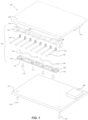
- FIG. 4 shows the primary electronics assembly 104 generally parallel to secondary electronics assembly 106 and attached together between upper and lower panels 112 and 114, which can be attached to each other with fasteners 116, as known in the art.
- Other fasteners can couple respective panels 112 and 114 to the primary and secondary electronics assemblies 104 and 106.
- the blind mate connector assembly 102 can be positioned between the primary and secondary electronics assembly 104 and 106 to facilitate a blind mate connection between the primary and secondary electronics assemblies 104 and 106.
- the blind mate connector assembly 102 can comprise a first manifold 120 that is removably coupled to a second manifold 122 to collectively form a connector housing body, for instance.
- a plurality of fasteners 124 are each positioned through respective apertures of the second manifold 122, as shown, and attached to receiving threads of the first manifold 120.
- These coupled first and second manifolds 120 and 122 can be removably attached to the first electronics assembly 104 using a pair of fasteners 126 (e.g., machine screws) disposed through apertures of the first electronics assembly 104.
- a plurality of cables 128, each comprising a cable line 130 and a cable connector 132, can electrically couple the primary electronics assembly 104 to the secondary electronics assembly 106.
- a particular cable line 130 e.g., coaxial cable
- a multi-contact device 133 can be a commercially available multi-contact RF module (or other backplane RF connector) attached to the primary electronics assembly 104.
- Such multi-contact device 133 can removably receive connector ends (not shown) of the cable lines 130, and therefore can electrically couple transmission of RF signals between the primary and secondary electronics assemblies 104 and 106, for example.
- the plurality of cables 128 can be commercially available as right angle coaxial cables that have connectors, such as SMPM connectors, SMP connectors, or similar connectors. However, this is not intended to be limiting in any way.
- a blind mate connecting portion 134 of each cable connector 132 e.g., a right angle connector
- the second manifold 122 can comprise a plurality of recesses 142 formed along an upper edge of the second manifold 122 at locations corresponding to the recesses 140 of the first manifold 120.
- each recess 140 and each (corresponding) recess 142 can form a second opening 144 through which a particular cable line 30 can pass or extend. See FIG. 4 specifically for an example arrangement of the cable line 30 extending loosely through the second opening 144.
- the mechanical float mechanism in this example can be defined by the second opening 144 being sized larger than the cable line 130 so that the second opening 144 loosely retains a portion of the cable line 130.
- a spring 146 (or other biasing device) can be situated within the connector cavity 137 and configured to bias each cable connector 132 in a z direction (as shown in the drawings) along the respective central axis A of the first opening 138 toward the secondary electronics assembly 106.
- the spring 146 can be one or more compliant dielectric/EMI strips, or the spring can be individual leaf springs or compression springs or O-rings positioned below each of the cable connectors 132.
- each spring 146 (being illustrated as a pair of compliant strips) can each be retained within and along a respective groove 148 formed in the second manifold 122.
- the first and second manifolds 120 and 122 can be removed from the primary electronics assembly 104 by removing fasteners 126 (after the secondary electronics assembly 106 is detached from the primary electronics assembly 104). Once the first and second manifolds 120 and 122 are collectively removed, the second manifold 122 can be detached from the first manifold 120 by removing fasteners 124, which then exposes the cable connectors 132 of the cables 128. Then, one or more cables 128 can be removed and replaced, and then the first and second manifolds 120 and 122 can be reattached to each other and then reattached to the primary electronics assembly 104.
- the first manifold 120 can have downwardly formed protrusions 115 on either end that are biased to the first electronics assembly 104 when attached thereto.
- This configuration positions the second manifold 122 above and away from the first electronics assembly 104 to avoid any unwanted electrical contact to the primary electronics assembly 104 with the fasteners 124 and/or cable lines 130.
- the first and second manifolds 120 and 122 can be comprised of a rigid dielectric material, such as polymer or plastic.
Landscapes
- Connector Housings Or Holding Contact Members (AREA)
Claims (14)
- Blindstecker Anordnung (102), umfassend:einen ersten Verteiler (120), der eine Vielzahl von ersten Öffnungen (138) umfasst, wobei jede eine Mittelachse (A) aufweist;einen zweiten Verteiler (122), der abnehmbar mit dem ersten Verteiler gekoppelt ist, um ein Verbindergehäuse zu definieren, das zwischen einer primären Elektronikanordnung (104) und einer sekundären Elektronikanordnung (106) positionierbar ist, wobei der zweite Verteiler eine Vielzahl von zweiten Öffnungen (144) umfasst, wobei jede eine Mittelachse (B) aufweist;eine Vielzahl von Verbindungshohlräumen (137), die durch die ersten und zweiten Verteiler definiert ist; undeine Vielzahl von rechtwinkligen Kabelverbindern (132), wobei sich jeder in einem der Vielzahl von Verbinderhohlräumen befindet und die rechtwinkligen Kabelverbinder einen Blindstecker zwischen der primären Elektronikanordnung und der sekundären Elektronikanordnung ermöglichen;wobei der erste und der zweite Verteiler lösbar miteinander gekoppelt sind, sodass das Entfernen des ersten Verteilers von dem zweiten Verteiler die Vielzahl der rechtwinkligen Kabelverbinder zum Entfernen aus den jeweiligen Verbinderhohlräumen freilegt; undferner umfassend einen mechanischen Schwebemechanismus, der mindestens eine Vorspannvorrichtung (146) umfasst, wobei jeder Verbinderhohlraum größer bemessen ist als ein entsprechender der rechtwinkligen Kabelverbinder, um die Bewegung des einen rechtwinkligen Kabelverbinders in mindestens drei linearen Freiheitsgraden und einem gewissen Maß an Drehbewegung zu erleichtern.
- Blindstecker Anordnung nach Anspruch 1, wobei der mechanische Schwebemechanismus ferner mindestens eines von Folgendem umfasst:wobei die Vielzahl von Verbinderhohlräumen (137) größer bemessen ist als der darin befindliche rechtwinklige Kabelverbinder (132), sodass die rechtwinkligen Kabelverbinder locker in den jeweiligen Verbinderhohlräumen gehalten werden;wobei die Vielzahl von ersten Öffnungen (138) jeweils größer bemessen ist als ein Blindstecker-Abschnitt (134) des rechtwinkligen Verbinders, um die Bewegung des Abschnitts in einer z-Richtung und in mindestens einer von einer x-Richtung und einer y-Richtung relativ zum Verbindergehäuse zu erleichtern;wobei die Vielzahl von zweiten Öffnungen (144) jeweils größer als eine Kabelleitung (130) bemessen ist, um die Bewegung der Kabelleitung innerhalb der entsprechenden zweiten Öffnung zu erleichtern.
- Blindstecker Anordnung nach Anspruch 1, wobei der mechanische Schwebemechanismus ferner eine Vielzahl von Federn (146) umfasst, die sich in jedem der Vielzahl von Verbinderhohlräumen (137) befindet und so konfiguriert ist, dass sie die Vielzahl von rechtwinkligen Kabelverbindern (132) in einer z-Richtung entlang der Mittelachse der entsprechenden Vielzahl von ersten Öffnungen (138) vorspannt.
- Blindstecker Anordnung nach Anspruch 1, wobei der zweite Verteiler (122) eine Nut (148) umfasst, die die Vielzahl von Verbinderhohlräumen (137) miteinander verbindet, und wobei der mechanische Schwebemechanismus ferner eine Feder (146) in Form einer länglichen Elastomerfeder umfasst, die in der Nut angeordnet ist und sich durch die Vielzahl von Verbinderhohlräumen erstreckt, um die Vielzahl von rechtwinkligen Kabelverbindern (132) in einer z-Richtung entlang der Mittelachse der ersten Öffnungen (138) vorzuspannen.
- Blindstecker Anordnung nach Anspruch 1, wobei jede der Vielzahl von zweiten Öffnungen (144) durch entsprechende Aussparungen (140, 142) in jedem der ersten (120) und zweiten (122) Verteiler definiert ist, wodurch die entsprechenden Aussparungen so ausgerichtet sind, dass sie den Durchgang einer an dem rechtwinkligen Kabelverbinder (132) befestigten Kabelleitung (130) erleichtern.
- Blindstecker Anordnung nach Anspruch 1, wobei die jeweiligen Mittelachsen der Vielzahl von ersten (138) und zweiten (144) Öffnungen orthogonal zueinander sind, sodass die Vielzahl von ersten Öffnungen orthogonal zu der Vielzahl von zweiten Öffnungen ausgerichtet ist.
- Elektronisches System (100), umfassend:eine primäre Elektronikanordnung (104);eine sekundäre Elektronikanordnung (106), die mechanisch und elektrisch mit der primären Elektronikanordnung gekoppelt ist;eine Blindstecker Anordnung (102) nach Anspruch 1, die zwischen der primären Elektronikanordnung und der sekundären Elektronikanordnung gekoppelt ist, wobei die Blindstecker Anordnung Folgendes umfasst:ein Gehäuse, das abnehmbar an der primären Elektronikanordnung befestigt ist, wobei das Gehäuse den ersten und den zweiten Verteiler (120, 122) umfasst, die die Vielzahl von Verbindungshohlräumen (137) definieren; undeine Vielzahl von Kabeln, die jeweils einen der rechtwinkligen Kabelverbinder (132) und eine von dem Kabelverbinder ausgehende Kabelleitung (130) umfasst,wobei sich jede Kabelleitung durch die jeweilige zweite Öffnung (144) erstreckt, die durch die ersten und zweiten Verteiler definiert ist, und jede Kabelleitung elektrisch mit der primären Elektronikanordnung gekoppelt ist, und wobei jeder rechtwinklige Kabelverbinder abnehmbar in einem der Vielzahl von Verbinderhohlräumen positioniert ist und über einen Blindstecker (134) des rechtwinkligen Kabelverbinders, der sich durch die jeweilige erste Öffnung (138) des ersten Verteilers erstreckt, mit der sekundären Elektronikanordnung verbunden ist.
- System nach Anspruch 7, wobei der erste Verteiler (120) und der zweite Verteiler (122) abnehmbar aneinander befestigt sind, um das Entfernen und Austauschen der Kabelverbinder (132) zu erleichtern.
- System nach Anspruch 8, ferner umfassend einen mechanischen Schwebemechanismus, umfassend mindestens eines von:der Vielzahl von Verbinderhohlräumen (137), die größer bemessen ist als der darin befindliche rechtwinklige Kabelverbinder (132), sodass die rechtwinkligen Kabelverbinder in den jeweiligen Verbinderhohlräumen passen; undder Vielzahl von ersten Öffnungen (138), die größer bemessen ist als die Blindstecker-Abschnitte (134) der entsprechenden rechtwinkligen Verbinder, um die Bewegung der zugehörigen Abschnitte in einer z-Richtung und in mindestens einer von einer x-Richtung und einer y-Richtung relativ zum Gehäuse zu erleichtern.
- System nach Anspruch 7, wobei der mechanische Schwebemechanismus die zweiten Öffnungen (144) umfasst, die größer bemessen sind als die entsprechenden Kabelleitungen (130), um die Bewegung der Kabelleitungen innerhalb der zweiten Öffnungen zu erleichtern und eine radiale Fehlausrichtung zwischen der primären (104) und sekundären (106) Elektronikanordnung zu ermöglichen.
- System nach Anspruch 7, wobei der mechanische Schwebemechanismus eine Feder (146) umfasst, die sich in jedem Verbinderhohlraum (137) befindet und so konfiguriert ist, dass sie jeden rechtwinkligen Kabelverbinder (132) in einer z-Richtung entlang einer Mittelachse (A) der ersten Öffnung (138) und in Richtung der sekundären Elektronikanordnung (106) vorspannt.
- System nach Anspruch 10, wobei jede der zweiten Öffnungen (144) durch entsprechende Aussparungen (140, 142) in jedem der ersten (120) und zweiten (122) Verteiler definiert ist, wobei die entsprechenden Aussparungen so ausgerichtet sind, dass sie den Durchgang der entsprechenden Kabelleitungen (130) erleichtern.
- System nach Anspruch 10, wobei die jeweiligen Mittelachsen (A, B) der ersten und zweiten Öffnungen (138, 144) orthogonal zueinander stehen, sodass die ersten Öffnungen (138) orthogonal zu den zweiten Öffnungen ausgerichtet sind.
- System nach Anspruch 12, wobei die Vielzahl der Kabel Hochfrequenz-Verbindungskabel sind.
Applications Claiming Priority (3)
| Application Number | Priority Date | Filing Date | Title |
|---|---|---|---|
| US15/459,295 US10243301B2 (en) | 2017-03-15 | 2017-03-15 | Blind mate connector housing and assembly |
| PCT/US2018/013613 WO2018169598A1 (en) | 2017-03-15 | 2018-01-12 | Blind mate connector housing and assembly |
| EP18709157.4A EP3596785B1 (de) | 2017-03-15 | 2018-01-12 | Blindsteckergehäuse und elektroniksystem |
Related Parent Applications (1)
| Application Number | Title | Priority Date | Filing Date |
|---|---|---|---|
| EP18709157.4A Division EP3596785B1 (de) | 2017-03-15 | 2018-01-12 | Blindsteckergehäuse und elektroniksystem |
Publications (2)
| Publication Number | Publication Date |
|---|---|
| EP4113752A1 EP4113752A1 (de) | 2023-01-04 |
| EP4113752B1 true EP4113752B1 (de) | 2024-07-03 |
Family
ID=61569379
Family Applications (2)
| Application Number | Title | Priority Date | Filing Date |
|---|---|---|---|
| EP18709157.4A Active EP3596785B1 (de) | 2017-03-15 | 2018-01-12 | Blindsteckergehäuse und elektroniksystem |
| EP22178991.0A Active EP4113752B1 (de) | 2017-03-15 | 2018-01-12 | Blindstecker anordnung und elektroniksystem |
Family Applications Before (1)
| Application Number | Title | Priority Date | Filing Date |
|---|---|---|---|
| EP18709157.4A Active EP3596785B1 (de) | 2017-03-15 | 2018-01-12 | Blindsteckergehäuse und elektroniksystem |
Country Status (3)
| Country | Link |
|---|---|
| US (1) | US10243301B2 (de) |
| EP (2) | EP3596785B1 (de) |
| WO (1) | WO2018169598A1 (de) |
Families Citing this family (5)
| Publication number | Priority date | Publication date | Assignee | Title |
|---|---|---|---|---|
| US10566722B2 (en) * | 2018-07-18 | 2020-02-18 | Getac Technology Corporation | Float-type connecting module and float-type docking device having the module |
| CN110247354B (zh) * | 2018-10-17 | 2023-11-24 | 广州番禺电缆集团有限公司 | 一种浮动式限位器 |
| JP7435048B2 (ja) * | 2019-05-10 | 2024-02-21 | 株式会社オートネットワーク技術研究所 | 接続装置およびコネクタ |
| US11399448B1 (en) * | 2021-02-25 | 2022-07-26 | Baidu Usa Llc | Full server liquid system auto-connecting design |
| WO2025109055A1 (de) * | 2023-11-21 | 2025-05-30 | Hirschmann Automotive Gmbh | Steckverbinder mit einem schwimmenden kontaktträger |
Family Cites Families (13)
| Publication number | Priority date | Publication date | Assignee | Title |
|---|---|---|---|---|
| US4892491A (en) * | 1988-12-19 | 1990-01-09 | Motorola, Inc. | Coaxial connector |
| US5676569A (en) * | 1996-07-25 | 1997-10-14 | The Whitaker Corporation | Holder for several electrical connectors |
| US6700464B2 (en) | 2002-02-21 | 2004-03-02 | Intel Corporation | Low cost high speed board-to-board coaxial connector design with co-planar waveguide for PCB launch |
| JP2006066384A (ja) | 2004-07-27 | 2006-03-09 | Hosiden Corp | 基板対基板接続用同軸コネクタ |
| US7165974B2 (en) | 2004-10-14 | 2007-01-23 | Corning Gilbert Inc. | Multiple-position push-on electrical connector |
| WO2009059440A1 (de) | 2007-11-07 | 2009-05-14 | Multi-Holding Ag | Stecker und steckverbindung für roboter |
| CN201438524U (zh) | 2009-08-06 | 2010-04-14 | 深圳速联连接器有限公司 | 板对板连接器 |
| US8029324B1 (en) * | 2010-11-04 | 2011-10-04 | Tyco Electronics Corporation | RF connector assembly |
| US8002574B1 (en) | 2010-11-04 | 2011-08-23 | Tyco Electronics Corporation | RF module with a housing with spring loaded connectors and a strain relief extending rearward of the housing |
| US8137134B1 (en) * | 2010-11-29 | 2012-03-20 | Ezconn Corporation | Coaxial cable connector with an insulating member with a bendable section with a pair of projections |
| US8360806B2 (en) * | 2010-12-22 | 2013-01-29 | Tyco Electronics Corporation | RF module |
| CN203589316U (zh) | 2013-09-26 | 2014-05-07 | 鲁建文 | 一种板到板射频同轴连接器的外壳结构 |
| EP3043425B1 (de) * | 2015-01-12 | 2020-12-16 | Amphenol Corporation | Schwimmeradapter für elektrischen verbinder |
-
2017
- 2017-03-15 US US15/459,295 patent/US10243301B2/en active Active
-
2018
- 2018-01-12 EP EP18709157.4A patent/EP3596785B1/de active Active
- 2018-01-12 EP EP22178991.0A patent/EP4113752B1/de active Active
- 2018-01-12 WO PCT/US2018/013613 patent/WO2018169598A1/en not_active Ceased
Also Published As
| Publication number | Publication date |
|---|---|
| EP3596785B1 (de) | 2022-06-15 |
| EP4113752A1 (de) | 2023-01-04 |
| WO2018169598A1 (en) | 2018-09-20 |
| EP3596785A1 (de) | 2020-01-22 |
| US20180269629A1 (en) | 2018-09-20 |
| US10243301B2 (en) | 2019-03-26 |
Similar Documents
| Publication | Publication Date | Title |
|---|---|---|
| EP4113752B1 (de) | Blindstecker anordnung und elektroniksystem | |
| EP2755282B1 (de) | Adapter | |
| EP2642615B1 (de) | Gehäuse eines elektrischen Moduls | |
| CN102396118B (zh) | 低损耗的板到板连接系统 | |
| EP3399597B1 (de) | Schwimmender elektrischer verbinder zum verbinden von leiterplatten and verfahren dafür | |
| CN102138256B (zh) | 构造用于使接头共地的载体组件和系统 | |
| EP3254341B1 (de) | Elektrischer verbinder mit verriegelungsanordnung | |
| CN108448302A (zh) | 电连接器组件及其转接件 | |
| US7281958B2 (en) | Power terminal block | |
| EP2175525A1 (de) | Verbinderanordnung mit einem Druckkopplungsglied | |
| CN106972301B (zh) | 用于电力连接器的具有顺应销的电力端子 | |
| CN108475860A (zh) | 具有多个同轴触头的同轴连接器组件和通信系统 | |
| CN106558782B (zh) | 互连设备 | |
| EP3467950B1 (de) | Verbinder | |
| US6358075B1 (en) | Mating alignment guide | |
| CN102544882A (zh) | 射频模块 | |
| US7465177B2 (en) | Electrical connector having a fluid coupling | |
| CN104103925A (zh) | 电触头和包括其的电连接器组件 | |
| CN113809563A (zh) | 集束电缆连接装置 | |
| US8758055B2 (en) | RF module | |
| US10050361B1 (en) | Flexible circuit connector | |
| CN105789945B (zh) | 用于电连接器的浮动适配器 | |
| KR200492776Y1 (ko) | 커넥터 | |
| US20120021620A1 (en) | Electrical connector with floating contact | |
| WO2023028369A1 (en) | Single-pair ethernet connector jack |
Legal Events
| Date | Code | Title | Description |
|---|---|---|---|
| PUAI | Public reference made under article 153(3) epc to a published international application that has entered the european phase |
Free format text: ORIGINAL CODE: 0009012 |
|
| STAA | Information on the status of an ep patent application or granted ep patent |
Free format text: STATUS: REQUEST FOR EXAMINATION WAS MADE |
|
| 17P | Request for examination filed |
Effective date: 20220614 |
|
| AC | Divisional application: reference to earlier application |
Ref document number: 3596785 Country of ref document: EP Kind code of ref document: P |
|
| AK | Designated contracting states |
Kind code of ref document: A1 Designated state(s): AL AT BE BG CH CY CZ DE DK EE ES FI FR GB GR HR HU IE IS IT LI LT LU LV MC MK MT NL NO PL PT RO RS SE SI SK SM TR |
|
| GRAP | Despatch of communication of intention to grant a patent |
Free format text: ORIGINAL CODE: EPIDOSNIGR1 |
|
| STAA | Information on the status of an ep patent application or granted ep patent |
Free format text: STATUS: GRANT OF PATENT IS INTENDED |
|
| RIC1 | Information provided on ipc code assigned before grant |
Ipc: H01R 9/05 20060101ALN20240207BHEP Ipc: H01R 12/91 20110101AFI20240207BHEP |
|
| RIC1 | Information provided on ipc code assigned before grant |
Ipc: H01R 9/05 20060101ALN20240213BHEP Ipc: H01R 12/91 20110101AFI20240213BHEP |
|
| INTG | Intention to grant announced |
Effective date: 20240226 |
|
| GRAS | Grant fee paid |
Free format text: ORIGINAL CODE: EPIDOSNIGR3 |
|
| GRAA | (expected) grant |
Free format text: ORIGINAL CODE: 0009210 |
|
| STAA | Information on the status of an ep patent application or granted ep patent |
Free format text: STATUS: THE PATENT HAS BEEN GRANTED |
|
| AC | Divisional application: reference to earlier application |
Ref document number: 3596785 Country of ref document: EP Kind code of ref document: P |
|
| AK | Designated contracting states |
Kind code of ref document: B1 Designated state(s): AL AT BE BG CH CY CZ DE DK EE ES FI FR GB GR HR HU IE IS IT LI LT LU LV MC MK MT NL NO PL PT RO RS SE SI SK SM TR |
|
| REG | Reference to a national code |
Ref country code: CH Ref legal event code: EP |
|
| REG | Reference to a national code |
Ref country code: DE Ref legal event code: R096 Ref document number: 602018071481 Country of ref document: DE |
|
| REG | Reference to a national code |
Ref country code: LT Ref legal event code: MG9D |
|
| REG | Reference to a national code |
Ref country code: NL Ref legal event code: MP Effective date: 20240703 |
|
| PG25 | Lapsed in a contracting state [announced via postgrant information from national office to epo] |
Ref country code: PT Free format text: LAPSE BECAUSE OF FAILURE TO SUBMIT A TRANSLATION OF THE DESCRIPTION OR TO PAY THE FEE WITHIN THE PRESCRIBED TIME-LIMIT Effective date: 20241104 |
|
| REG | Reference to a national code |
Ref country code: AT Ref legal event code: MK05 Ref document number: 1700816 Country of ref document: AT Kind code of ref document: T Effective date: 20240703 |
|
| PG25 | Lapsed in a contracting state [announced via postgrant information from national office to epo] |
Ref country code: NL Free format text: LAPSE BECAUSE OF FAILURE TO SUBMIT A TRANSLATION OF THE DESCRIPTION OR TO PAY THE FEE WITHIN THE PRESCRIBED TIME-LIMIT Effective date: 20240703 |
|
| PG25 | Lapsed in a contracting state [announced via postgrant information from national office to epo] |
Ref country code: PT Free format text: LAPSE BECAUSE OF FAILURE TO SUBMIT A TRANSLATION OF THE DESCRIPTION OR TO PAY THE FEE WITHIN THE PRESCRIBED TIME-LIMIT Effective date: 20241104 Ref country code: NL Free format text: LAPSE BECAUSE OF FAILURE TO SUBMIT A TRANSLATION OF THE DESCRIPTION OR TO PAY THE FEE WITHIN THE PRESCRIBED TIME-LIMIT Effective date: 20240703 |
|
| PG25 | Lapsed in a contracting state [announced via postgrant information from national office to epo] |
Ref country code: NO Free format text: LAPSE BECAUSE OF FAILURE TO SUBMIT A TRANSLATION OF THE DESCRIPTION OR TO PAY THE FEE WITHIN THE PRESCRIBED TIME-LIMIT Effective date: 20241003 |
|
| PG25 | Lapsed in a contracting state [announced via postgrant information from national office to epo] |
Ref country code: GR Free format text: LAPSE BECAUSE OF FAILURE TO SUBMIT A TRANSLATION OF THE DESCRIPTION OR TO PAY THE FEE WITHIN THE PRESCRIBED TIME-LIMIT Effective date: 20241004 Ref country code: FI Free format text: LAPSE BECAUSE OF FAILURE TO SUBMIT A TRANSLATION OF THE DESCRIPTION OR TO PAY THE FEE WITHIN THE PRESCRIBED TIME-LIMIT Effective date: 20240703 Ref country code: PL Free format text: LAPSE BECAUSE OF FAILURE TO SUBMIT A TRANSLATION OF THE DESCRIPTION OR TO PAY THE FEE WITHIN THE PRESCRIBED TIME-LIMIT Effective date: 20240703 |
|
| PG25 | Lapsed in a contracting state [announced via postgrant information from national office to epo] |
Ref country code: BG Free format text: LAPSE BECAUSE OF FAILURE TO SUBMIT A TRANSLATION OF THE DESCRIPTION OR TO PAY THE FEE WITHIN THE PRESCRIBED TIME-LIMIT Effective date: 20240703 |
|
| PG25 | Lapsed in a contracting state [announced via postgrant information from national office to epo] |
Ref country code: LV Free format text: LAPSE BECAUSE OF FAILURE TO SUBMIT A TRANSLATION OF THE DESCRIPTION OR TO PAY THE FEE WITHIN THE PRESCRIBED TIME-LIMIT Effective date: 20240703 |
|
| PG25 | Lapsed in a contracting state [announced via postgrant information from national office to epo] |
Ref country code: IS Free format text: LAPSE BECAUSE OF FAILURE TO SUBMIT A TRANSLATION OF THE DESCRIPTION OR TO PAY THE FEE WITHIN THE PRESCRIBED TIME-LIMIT Effective date: 20241103 Ref country code: AT Free format text: LAPSE BECAUSE OF FAILURE TO SUBMIT A TRANSLATION OF THE DESCRIPTION OR TO PAY THE FEE WITHIN THE PRESCRIBED TIME-LIMIT Effective date: 20240703 |
|
| PG25 | Lapsed in a contracting state [announced via postgrant information from national office to epo] |
Ref country code: CZ Free format text: LAPSE BECAUSE OF FAILURE TO SUBMIT A TRANSLATION OF THE DESCRIPTION OR TO PAY THE FEE WITHIN THE PRESCRIBED TIME-LIMIT Effective date: 20240703 Ref country code: HR Free format text: LAPSE BECAUSE OF FAILURE TO SUBMIT A TRANSLATION OF THE DESCRIPTION OR TO PAY THE FEE WITHIN THE PRESCRIBED TIME-LIMIT Effective date: 20240703 |
|
| PG25 | Lapsed in a contracting state [announced via postgrant information from national office to epo] |
Ref country code: RS Free format text: LAPSE BECAUSE OF FAILURE TO SUBMIT A TRANSLATION OF THE DESCRIPTION OR TO PAY THE FEE WITHIN THE PRESCRIBED TIME-LIMIT Effective date: 20241003 Ref country code: ES Free format text: LAPSE BECAUSE OF FAILURE TO SUBMIT A TRANSLATION OF THE DESCRIPTION OR TO PAY THE FEE WITHIN THE PRESCRIBED TIME-LIMIT Effective date: 20240703 |
|
| PG25 | Lapsed in a contracting state [announced via postgrant information from national office to epo] |
Ref country code: RS Free format text: LAPSE BECAUSE OF FAILURE TO SUBMIT A TRANSLATION OF THE DESCRIPTION OR TO PAY THE FEE WITHIN THE PRESCRIBED TIME-LIMIT Effective date: 20241003 Ref country code: PL Free format text: LAPSE BECAUSE OF FAILURE TO SUBMIT A TRANSLATION OF THE DESCRIPTION OR TO PAY THE FEE WITHIN THE PRESCRIBED TIME-LIMIT Effective date: 20240703 Ref country code: NO Free format text: LAPSE BECAUSE OF FAILURE TO SUBMIT A TRANSLATION OF THE DESCRIPTION OR TO PAY THE FEE WITHIN THE PRESCRIBED TIME-LIMIT Effective date: 20241003 Ref country code: LV Free format text: LAPSE BECAUSE OF FAILURE TO SUBMIT A TRANSLATION OF THE DESCRIPTION OR TO PAY THE FEE WITHIN THE PRESCRIBED TIME-LIMIT Effective date: 20240703 Ref country code: IS Free format text: LAPSE BECAUSE OF FAILURE TO SUBMIT A TRANSLATION OF THE DESCRIPTION OR TO PAY THE FEE WITHIN THE PRESCRIBED TIME-LIMIT Effective date: 20241103 Ref country code: HR Free format text: LAPSE BECAUSE OF FAILURE TO SUBMIT A TRANSLATION OF THE DESCRIPTION OR TO PAY THE FEE WITHIN THE PRESCRIBED TIME-LIMIT Effective date: 20240703 Ref country code: GR Free format text: LAPSE BECAUSE OF FAILURE TO SUBMIT A TRANSLATION OF THE DESCRIPTION OR TO PAY THE FEE WITHIN THE PRESCRIBED TIME-LIMIT Effective date: 20241004 Ref country code: FI Free format text: LAPSE BECAUSE OF FAILURE TO SUBMIT A TRANSLATION OF THE DESCRIPTION OR TO PAY THE FEE WITHIN THE PRESCRIBED TIME-LIMIT Effective date: 20240703 Ref country code: ES Free format text: LAPSE BECAUSE OF FAILURE TO SUBMIT A TRANSLATION OF THE DESCRIPTION OR TO PAY THE FEE WITHIN THE PRESCRIBED TIME-LIMIT Effective date: 20240703 Ref country code: CZ Free format text: LAPSE BECAUSE OF FAILURE TO SUBMIT A TRANSLATION OF THE DESCRIPTION OR TO PAY THE FEE WITHIN THE PRESCRIBED TIME-LIMIT Effective date: 20240703 Ref country code: BG Free format text: LAPSE BECAUSE OF FAILURE TO SUBMIT A TRANSLATION OF THE DESCRIPTION OR TO PAY THE FEE WITHIN THE PRESCRIBED TIME-LIMIT Effective date: 20240703 Ref country code: AT Free format text: LAPSE BECAUSE OF FAILURE TO SUBMIT A TRANSLATION OF THE DESCRIPTION OR TO PAY THE FEE WITHIN THE PRESCRIBED TIME-LIMIT Effective date: 20240703 |
|
| REG | Reference to a national code |
Ref country code: DE Ref legal event code: R097 Ref document number: 602018071481 Country of ref document: DE |
|
| PG25 | Lapsed in a contracting state [announced via postgrant information from national office to epo] |
Ref country code: RO Free format text: LAPSE BECAUSE OF FAILURE TO SUBMIT A TRANSLATION OF THE DESCRIPTION OR TO PAY THE FEE WITHIN THE PRESCRIBED TIME-LIMIT Effective date: 20240703 Ref country code: SM Free format text: LAPSE BECAUSE OF FAILURE TO SUBMIT A TRANSLATION OF THE DESCRIPTION OR TO PAY THE FEE WITHIN THE PRESCRIBED TIME-LIMIT Effective date: 20240703 Ref country code: DK Free format text: LAPSE BECAUSE OF FAILURE TO SUBMIT A TRANSLATION OF THE DESCRIPTION OR TO PAY THE FEE WITHIN THE PRESCRIBED TIME-LIMIT Effective date: 20240703 |
|
| PG25 | Lapsed in a contracting state [announced via postgrant information from national office to epo] |
Ref country code: EE Free format text: LAPSE BECAUSE OF FAILURE TO SUBMIT A TRANSLATION OF THE DESCRIPTION OR TO PAY THE FEE WITHIN THE PRESCRIBED TIME-LIMIT Effective date: 20240703 |
|
| PG25 | Lapsed in a contracting state [announced via postgrant information from national office to epo] |
Ref country code: SK Free format text: LAPSE BECAUSE OF FAILURE TO SUBMIT A TRANSLATION OF THE DESCRIPTION OR TO PAY THE FEE WITHIN THE PRESCRIBED TIME-LIMIT Effective date: 20240703 Ref country code: IT Free format text: LAPSE BECAUSE OF FAILURE TO SUBMIT A TRANSLATION OF THE DESCRIPTION OR TO PAY THE FEE WITHIN THE PRESCRIBED TIME-LIMIT Effective date: 20240703 |
|
| PLBE | No opposition filed within time limit |
Free format text: ORIGINAL CODE: 0009261 |
|
| STAA | Information on the status of an ep patent application or granted ep patent |
Free format text: STATUS: NO OPPOSITION FILED WITHIN TIME LIMIT |
|
| 26N | No opposition filed |
Effective date: 20250404 |
|
| REG | Reference to a national code |
Ref country code: CH Ref legal event code: PL |
|
| PG25 | Lapsed in a contracting state [announced via postgrant information from national office to epo] |
Ref country code: SE Free format text: LAPSE BECAUSE OF FAILURE TO SUBMIT A TRANSLATION OF THE DESCRIPTION OR TO PAY THE FEE WITHIN THE PRESCRIBED TIME-LIMIT Effective date: 20240703 |
|
| PG25 | Lapsed in a contracting state [announced via postgrant information from national office to epo] |
Ref country code: MC Free format text: LAPSE BECAUSE OF FAILURE TO SUBMIT A TRANSLATION OF THE DESCRIPTION OR TO PAY THE FEE WITHIN THE PRESCRIBED TIME-LIMIT Effective date: 20240703 Ref country code: LU Free format text: LAPSE BECAUSE OF NON-PAYMENT OF DUE FEES Effective date: 20250112 |
|
| PG25 | Lapsed in a contracting state [announced via postgrant information from national office to epo] |
Ref country code: BE Free format text: LAPSE BECAUSE OF NON-PAYMENT OF DUE FEES Effective date: 20250131 |
|
| PG25 | Lapsed in a contracting state [announced via postgrant information from national office to epo] |
Ref country code: CH Free format text: LAPSE BECAUSE OF NON-PAYMENT OF DUE FEES Effective date: 20250131 |
|
| REG | Reference to a national code |
Ref country code: BE Ref legal event code: MM Effective date: 20250131 |
|
| PGFP | Annual fee paid to national office [announced via postgrant information from national office to epo] |
Ref country code: GB Payment date: 20251219 Year of fee payment: 9 |
|
| PGFP | Annual fee paid to national office [announced via postgrant information from national office to epo] |
Ref country code: FR Payment date: 20251217 Year of fee payment: 9 |
|
| PG25 | Lapsed in a contracting state [announced via postgrant information from national office to epo] |
Ref country code: IE Free format text: LAPSE BECAUSE OF NON-PAYMENT OF DUE FEES Effective date: 20250112 |
|
| PGFP | Annual fee paid to national office [announced via postgrant information from national office to epo] |
Ref country code: DE Payment date: 20251217 Year of fee payment: 9 |