EP4115105B1 - Ventil - Google Patents
Ventil Download PDFInfo
- Publication number
- EP4115105B1 EP4115105B1 EP21707952.4A EP21707952A EP4115105B1 EP 4115105 B1 EP4115105 B1 EP 4115105B1 EP 21707952 A EP21707952 A EP 21707952A EP 4115105 B1 EP4115105 B1 EP 4115105B1
- Authority
- EP
- European Patent Office
- Prior art keywords
- shaft
- housing
- valve
- adjusting device
- receptacle
- Prior art date
- Legal status (The legal status is an assumption and is not a legal conclusion. Google has not performed a legal analysis and makes no representation as to the accuracy of the status listed.)
- Active
Links
Images

Classifications
-
- F—MECHANICAL ENGINEERING; LIGHTING; HEATING; WEAPONS; BLASTING
- F16—ENGINEERING ELEMENTS AND UNITS; GENERAL MEASURES FOR PRODUCING AND MAINTAINING EFFECTIVE FUNCTIONING OF MACHINES OR INSTALLATIONS; THERMAL INSULATION IN GENERAL
- F16K—VALVES; TAPS; COCKS; ACTUATING-FLOATS; DEVICES FOR VENTING OR AERATING
- F16K35/00—Means to prevent accidental or unauthorised actuation
- F16K35/02—Means to prevent accidental or unauthorised actuation to be locked or disconnected by means of a pushing or pulling action
- F16K35/022—Means to prevent accidental or unauthorised actuation to be locked or disconnected by means of a pushing or pulling action the locking mechanism being actuated by a separate actuating element
- F16K35/025—Means to prevent accidental or unauthorised actuation to be locked or disconnected by means of a pushing or pulling action the locking mechanism being actuated by a separate actuating element said actuating element being operated manually (e.g. a push-button located in the valve actuator)
-
- F—MECHANICAL ENGINEERING; LIGHTING; HEATING; WEAPONS; BLASTING
- F16—ENGINEERING ELEMENTS AND UNITS; GENERAL MEASURES FOR PRODUCING AND MAINTAINING EFFECTIVE FUNCTIONING OF MACHINES OR INSTALLATIONS; THERMAL INSULATION IN GENERAL
- F16K—VALVES; TAPS; COCKS; ACTUATING-FLOATS; DEVICES FOR VENTING OR AERATING
- F16K1/00—Lift valves or globe valves, i.e. cut-off apparatus with closure members having at least a component of their opening and closing motion perpendicular to the closing faces
- F16K1/16—Lift valves or globe valves, i.e. cut-off apparatus with closure members having at least a component of their opening and closing motion perpendicular to the closing faces with pivoted closure-members
- F16K1/18—Lift valves or globe valves, i.e. cut-off apparatus with closure members having at least a component of their opening and closing motion perpendicular to the closing faces with pivoted closure-members with pivoted discs or flaps
- F16K1/22—Lift valves or globe valves, i.e. cut-off apparatus with closure members having at least a component of their opening and closing motion perpendicular to the closing faces with pivoted closure-members with pivoted discs or flaps with axis of rotation crossing the valve member, e.g. butterfly valves
- F16K1/221—Lift valves or globe valves, i.e. cut-off apparatus with closure members having at least a component of their opening and closing motion perpendicular to the closing faces with pivoted closure-members with pivoted discs or flaps with axis of rotation crossing the valve member, e.g. butterfly valves specially adapted operating means therefor
-
- F—MECHANICAL ENGINEERING; LIGHTING; HEATING; WEAPONS; BLASTING
- F16—ENGINEERING ELEMENTS AND UNITS; GENERAL MEASURES FOR PRODUCING AND MAINTAINING EFFECTIVE FUNCTIONING OF MACHINES OR INSTALLATIONS; THERMAL INSULATION IN GENERAL
- F16K—VALVES; TAPS; COCKS; ACTUATING-FLOATS; DEVICES FOR VENTING OR AERATING
- F16K31/00—Actuating devices; Operating means; Releasing devices
- F16K31/44—Mechanical actuating means
- F16K31/60—Handles
- F16K31/602—Pivoting levers, e.g. single-sided
-
- F—MECHANICAL ENGINEERING; LIGHTING; HEATING; WEAPONS; BLASTING
- F16—ENGINEERING ELEMENTS AND UNITS; GENERAL MEASURES FOR PRODUCING AND MAINTAINING EFFECTIVE FUNCTIONING OF MACHINES OR INSTALLATIONS; THERMAL INSULATION IN GENERAL
- F16K—VALVES; TAPS; COCKS; ACTUATING-FLOATS; DEVICES FOR VENTING OR AERATING
- F16K35/00—Means to prevent accidental or unauthorised actuation
- F16K35/02—Means to prevent accidental or unauthorised actuation to be locked or disconnected by means of a pushing or pulling action
- F16K35/027—Means to prevent accidental or unauthorised actuation to be locked or disconnected by means of a pushing or pulling action the locking mechanism being actuated by pushing or pulling the valve actuator, the valve actuator being rotated subsequently to bring the valve closure element in the desired position
-
- F—MECHANICAL ENGINEERING; LIGHTING; HEATING; WEAPONS; BLASTING
- F16—ENGINEERING ELEMENTS AND UNITS; GENERAL MEASURES FOR PRODUCING AND MAINTAINING EFFECTIVE FUNCTIONING OF MACHINES OR INSTALLATIONS; THERMAL INSULATION IN GENERAL
- F16K—VALVES; TAPS; COCKS; ACTUATING-FLOATS; DEVICES FOR VENTING OR AERATING
- F16K35/00—Means to prevent accidental or unauthorised actuation
- F16K35/06—Means to prevent accidental or unauthorised actuation using a removable actuating or locking member, e.g. a key
-
- F—MECHANICAL ENGINEERING; LIGHTING; HEATING; WEAPONS; BLASTING
- F16—ENGINEERING ELEMENTS AND UNITS; GENERAL MEASURES FOR PRODUCING AND MAINTAINING EFFECTIVE FUNCTIONING OF MACHINES OR INSTALLATIONS; THERMAL INSULATION IN GENERAL
- F16K—VALVES; TAPS; COCKS; ACTUATING-FLOATS; DEVICES FOR VENTING OR AERATING
- F16K35/00—Means to prevent accidental or unauthorised actuation
- F16K35/10—Means to prevent accidental or unauthorised actuation with locking caps or locking bars
Definitions
- Valves of the generic type are used in systems for the production of food, beverages, medicines and fine chemical products as well as in biotechnology.
- the WO 2011/123128 A1 presents a valve for controlling gas flows.
- a closing member is attached to a valve rod, which passes through a sleeve rotatably mounted in a housing.
- a handwheel is attached to the sleeve. Turning the handwheel causes the sleeve to rotate. This rotation is translated into an axial movement of the valve rod by means of threads on the valve rod and sleeve.
- the valve rod protrudes from the handwheel and has a cross hole to accommodate a bracket of a U-lock. As a result, the valve can be blocked in an open position of the closing member.
- the WO 2000/022327 A1 proposes a hand-operated valve whose valve rod can be adjusted in an axial direction using a handwheel. This adjustment can be blocked using a U-lock, the shackle of which is inserted through a hole in the handwheel.
- a disc valve with a hand lever adjustment of the closing element provides the DE 10 2013 005 458 A1 before.
- a retrofittable component is proposed which surrounds the part of the valve where the hand lever is connected to the valve rod.
- the component has at least one opening through which a shackle of a U-lock can be inserted. If the hand lever passes through the bracket of the With the U-lock mounted on the component in this way, the valve is secured against adjustment of the closing element.
- a valve is known with a locking device for locking the valve.
- the locking device comprises a housing with at least one bore and a spindle arranged in the housing with a pair of transverse bores and a locking pin which can be selectively inserted into the housing bore and one of the spindle bores in order to allow rotation of the spindle relative to the housing in a first or to lock second position.
- An existing valve should be able to be retrofitted with the locking device.
- the valve has a closing member which can be brought from a closed position to an open position by a rotary movement about an axis of rotation transverse to a flow direction.
- the closing member can be shaped as a disk.
- a valve of this type is also called a disc valve and includes a shaft that is connected to the closing member and that includes a shaft end.
- Valves in which the closing member and shaft are manufactured as one part, for example by using a forging process, are cost-effective and hygienic.
- the valve further comprises a valve housing, an adjusting device, which has an adjusting device housing and includes a receptacle in which the shaft end can be received.
- a shaft section comprises a passage, which can be brought into congruence with two openings on the housing side, and that the passage and openings can be passed through by a securing body, and the connection of the shaft and shaft section is secured against loosening when the passage and openings are in congruence condition.
- “Housing side” means an arrangement on one standing part of the valve or a component attached to it. In the case of the adjustment device, it is the adjustment device housing. "Openings" can be drilled through holes or U-shaped recesses. The function to be fulfilled is to fix the securing body against rotational movement around the axis of rotation.
- the blocking of the movement of the closing member takes place in the manner presented close to the axis of rotation and not radially offset from it as in the prior art.
- the risk of incorrect operation or bypassing the blockage is greatly reduced in this way.
- the arrangement is inexpensive and can be retrofitted.
- a structurally simple and cost-effective retrofitting is achieved by arranging an intermediate housing between the adjusting device and the valve and having an intermediate shaft which is coupled to the adjusting shaft of the adjusting device and the shaft of the valve.
- the intermediate shaft then takes over the function of the shaft section.
- the security of the arrangement against unintentional actuation of the valve is increased in that the shaft and intermediate shaft are secured with a screw connection, with a cover covering the screw in particular when the valve is in the switching position to be blocked.
- the screw is then no longer accessible and the shaft and intermediate shaft are reliably connected to each other.
- the locking element can no longer be fixed.
- a bolt is used as a locking device. It has a head which is larger than the hole in the passage, so that the securing body is positively secured in a first direction.
- the fixing is done, for example, by a U-lock, which goes through a transverse bore of the securing body is inserted, this transverse bore being arranged on the side of the adjusting device or intermediate housing opposite the head.
- a U-lock which goes through a transverse bore of the securing body is inserted, this transverse bore being arranged on the side of the adjusting device or intermediate housing opposite the head.
- the presented embodiments advantageously work together safely with adjustment devices that include a hand lever for manual actuation of the valve.
- the versions can also be used with pneumatic adjustment devices.
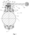
- Fig. 1 shows a valve 110 with a closing member 112, which can be brought from a closed position to an open position by a rotational movement about an axis of rotation Q which is transverse to a flow direction L, with a shaft 114 which is connected to the closing member and which includes a shaft end 116, with a valve housing 118, with an adjusting device 120, which has an adjusting device housing 122 and an adjusting shaft 124 has a receptacle 126 in which the shaft end 116 can be received, and is characterized in that the actuating shaft 124 has a passage 128 includes, which can be brought into congruence with two holes in the adjusting device housing 122, passage and holes can be passed through by a securing body 130, and the axis of rotation Q intersects the securing body 130.
- the actuating shaft 124 forms a shaft section which includes the passage 128, which can be brought into congruence with two openings on the housing side, and passage 128 and openings 158 can be passed through by a securing body 130, and the connection of shaft and shaft section is secured against loosening when passage 128 and openings 158 are in cover.
- the security body 130 can be a bracket of a U-lock. Since this requires a special U-lock for large valves, it is advantageous to design the security body 130 as an independent component and to provide it with a hole which receives the bracket 132 of a standard U-lock 134.
- the shaft end 116 received in the receptacle 126 of the actuating shaft 124 can be secured against rotation relative to one another by a positive design of the receptacle 126 and the shaft end 116.
- a screw 136 secures this connection of the adjusting shaft 124 and the shaft end 116 against movement in the direction of the transverse axis Q.
- the screw 136 is accessible via an opening 138 in the adjusting device housing 122.
- a cover for the opening 138 can be provided.
- This cover is advantageously fixed by the U-lock 134.
- it can be permanently connected to the securing body 130, for example by a material connection.
- the cover can, for example, be designed as a shell section (half-shell or the like), which nestles against an outer wall of the adjusting device housing 122.
- the adjusting device housing 122 has at least one form-fitting element 140, which engages with the valve housing 118 and prevents the adjusting device housing 122 from rotating against the valve housing 118.
- the adjusting device 120 has a hand lever 142, which is movable in a radial direction transverse to the transverse axis Q against the force of a spring 144. With this movement, a nose 146 is removed from a locking receptacle 148 on the adjusting device housing 122. Only when the nose 146 is removed from the locking receptacle 148 is the actuating shaft 124 able to rotate about the transverse axis Q. If the nose 146 is accommodated in the locking receptacle 148, the actuating shaft 124 is secured against rotation about the transverse axis Q.
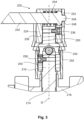
- Fig. 2 , Fig. 3 and Fig. 4 show a further development of the valve described according to the invention.
- a section through a valve 210 with a closing member 212 designed as a disk is shown.
- the closing member 212 is rotatably mounted in a valve housing 218 about a transverse axis Q.
- the transverse axis Q is transverse to the flow direction L, along which flow can flow through the valve housing 218, for example at a right angle.
- the rotation of the closing member 212 about the transverse axis Q can be effected with the help of an adjusting device 220. This can have a hand lever 242.
- the adjusting device 220 also has a hand lever 242 held in an adjusting device housing 222.
- the hand lever 242 is movable relative to the adjuster housing 222 against the force of a spring 244 in order to move a nose 246, which is provided at one of its ends, out of a locking receptacle 248.
- the hand lever 242 is not movable in a circumferential direction about the transverse axis Q.
- This movement in the circumferential direction is possible. This movement causes the actuating shaft 224 to rotate about the transverse axis Q.
- the rotation of the actuating shaft 224 is transmitted to an intermediate shaft 250 which is connected to it and forms a shaft section and which is received in sections in a receptacle 226.
- Recording 226 and the section of the intermediate shaft 250 received therein are designed to transmit force, for example by forming a positive connection in the circumferential direction around the transverse axis Q. This positive connection can be replaced or supported with a screw 236.
- the intermediate shaft 250 is rotatably accommodated in an intermediate housing 252, which is supported in a rotationally fixed manner on the valve housing 218.
- the intermediate shaft 250 has a second receptacle 254 in which the shaft end 216 connected to the closing member is accommodated in a rotationally fixed manner. This arrangement converts a rotation of the actuating shaft 224 about the transverse axis Q initiated with the hand lever 242 into a rotation of the shaft 214 and brings the valve 210 from a closed to an open position and vice versa.
- connection of intermediate shaft 250 and shaft 214 can advantageously be secured, for example with a second screw 256.
- This passes through an opening in the second receptacle 254 and is in engagement with a thread in the shaft end 216, so that at least a positive connection against movement along the transverse axis Q is created.
- the second screw 256 is advantageous to arrange the second screw 256 in at least one angular position of the intermediate shaft 250 covered by the intermediate housing 252. This is preferably the angular position in which the valve should be secured. This prevents removal of the second screw 256 and fixes the valve even more securely in its position.
- the intermediate shaft 250 can be blocked against rotation about the transverse axis Q by a securing body 230 passing through openings and/or recesses in the intermediate shaft 250 and in the intermediate housing 252.
- the security body 230 can in turn be secured against removal by a U-lock.
- the intermediate shaft 250 can have more than one opening or recess, which are arranged angularly offset from one another, so that the valve can be fixed in one of several positions.
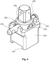
- FIG. 4 the intermediate housing 252 is shown in a perspective view.
- a passage 228 for receiving the fuse body 230 is easier to see in this illustration.
- the passage 228 openings 258 can be brought into line so that the securing body 230 passes through the passage 228 and opening 258. This blocks further rotation of the intermediate shaft 250.
- the opening can be a hole, a bore or a recess.
- a form-fitting element 240 can also be seen, which ensures the support of the intermediate housing 252 on the Valve housing 218 counteracts rotation about the transverse axis Q.
- the intermediate shaft 250 has flat surfaces 260.
- the flat surfaces 260 create a multi-surface which interacts with a corresponding multi-surface in the receptacle 226, so that the intermediate shaft 250 is received in a form-fitting manner in the receptacle 226.
- FIG. 2 An additional advantage of using the Fig. 2 to Fig. 4
- the exemplary embodiment explained is that the intermediate housing 252 and intermediate shaft 250 can be retrofitted to existing valves. This advantage is deepened by the receptacle 226 and the second receptacle 254 being shaped geometrically similar to one another.
- This example therefore describes a valve 210 with a closing member 212, which can be brought from a closed position to an open position by a rotational movement about an axis of rotation Q which is transverse to a flow direction L, with a shaft 214 which is connected to the closing member 212 and which is a Shaft end 216 includes, with a valve housing 218, with an adjusting device 220, which has an adjusting device housing 222 and includes a receptacle 226 in which the shaft end 216 can be received, and with an intermediate housing 252 with an intermediate shaft 250 rotatably received therein, which is connected to the shaft 214 connected and recorded in the receptacle 226.
- This valve 210 is characterized in that the intermediate shaft 250 comprises a passage 228, which can be brought into congruence with two openings 258 in the intermediate housing, and passage 228 and openings 258 can be passed through by a securing body 230, and the connection of shaft 214 and intermediate shaft 250 is secured against loosening when passage 228 and openings 258 are in line.
- the exemplary embodiment according to the Fig. 2 , 3 and 4 is shown with an adjustment device that can be operated manually.
- the adjusting device can also be designed to be operated by pressure medium, for example pneumatically.
- it makes sense to make the connections between the adjusting device and the intermediate housing and between the intermediate housing and the valve housing secure. This can be done, for example, with the help of screws which pass through a flange on a first component, for example an adjusting device housing and an intermediate housing, and are accommodated in threads in the respectively assigned other component, for example an intermediate housing and a valve housing.
- the number of screws in the respective connection depends, among other things, on the valve size and the forces and torques transmitted via the shaft between the adjusting device and the closing element.
- valve is fixed in a position not by fixing an operating element of the adjusting device such as the hand lever or a handwheel, but rather by blocking the shaft of the valve or a shaft connected to it as directly as possible.
Landscapes
- Engineering & Computer Science (AREA)
- General Engineering & Computer Science (AREA)
- Mechanical Engineering (AREA)
- Preventing Unauthorised Actuation Of Valves (AREA)
- Mechanically-Actuated Valves (AREA)
Description
- Ventile der gattungsgemäßen Art werden in Anlagen zur Herstellung von Lebensmitteln, Getränken, Medikamenten und feinchemischen Produkten sowie in der Biotechnologie eingesetzt.
- Während der Wartung solcher Anlagen ist es wichtig, wenigstens Teile von ihr in einen definierten Zustand zu bringen und sicher in diesem zu halten. Beispielsweise kann es notwendig sein, ein Rohrstück mit einem Gerät auszutauschen und dieses Rohrstück aus der Anlage zu entfernen. Damit das Rohrstück entfernt werden kann, wird davor und dahinter ein Ventil abgesperrt. Solange das Rohrstück entfernt ist, ist Sorge dafür zu tragen, dass die Ventile abgesperrt bleiben, da sonst Kontamination der Anlage und/oder Verlust von Produkt droht.
- Die
WO 2011/123128 A1 stellt ein Ventil zum Steuern von Gasströmen vor. Ein Schließglied ist an einer Ventilstange befestigt, welche eine drehbar in einem Gehäuse gelagerten Hülse durchsetzt. An der Hülse ist ein Handrad befestigt. Eine Drehung des Handrades bewirkt eine Drehung der Hülse. Diese Drehung wird mittels Gewinde an Ventilstange und Hülse in eine axiale Bewegung der Ventilstange übersetzt. Die Ventilstange ragt aus dem Handrad und besitzt eine Querbohrung zur Aufnahme eines Bügels eines Bügelschlosses. Hierdurch ist das Ventil in einer Offenstellung des Schließgliedes blockierbar. - Die
WO 2000/022327 A1 schlägt ein handbetriebenes Ventil vor, dessen Ventilstange mit Hilfe eines Handrades in eine axiale Richtung verstellbar ist. Diese Verstellung kann durch eine Bügelschloss blockiert werden, dessen Bügel durch ein Loch im Handrad gesteckt wird. - Ein Scheibenventil mit einer Handhebelverstellung des Schließgliedes stellt die
DE 10 2013 005 458 A1 vor. Es wird ein nachrüstbares Bauteil vorgeschlagen, welches den Teil des Ventils umgibt, an dem der Handhebel mit der Ventilstange verbunden ist. Das Bauteil besitzt wenigstens eine Öffnung, durch die ein Bügel eines Bügelschlosses gesteckt werden kann. Durchsetzt der Handhebel den Bügel des auf diese Weise am Bauteil montierten Bügelschlosses, ist das Ventil gegen Verstellung des Schließgliedes gesichert. - Aus
US 5 236 172 A ist ein Ventil bekannt mit einer Sperrvorrichtung zum Sperren des Ventils. Die Sperrvorrichtung umfasst ein Gehäuse mit mindestens einer Bohrung und einer in dem Gehäuse angeordneten Spindel mit einem Paar von Querbohrungen sowie einen Sperrstift, der wahlweise in die Gehäusebohrung und eine der Spindelbohrungen einsetzbar ist, um eine Drehung der Spindel relativ zu dem Gehäuse in einer ersten oder zweiten Position zu sperren. Dabei soll ein bestehendes Ventil mit der Sperrvorrichtung nachrüstbar sein. - Es war nun daher Aufgabe der Erfindung, ein Ventil zu schaffen, welches kostengünstig mit erhöhter Sicherheit in einer Position festgelegt werden kann.
- Diese Aufgabe wird gelöst durch ein Ventil mit den Merkmalen des Anspruchs 1. Die abhängigen Ansprüche geben vorteilhafte Weiterbildungen an.
- Das Ventil besitzt ein Schließglied, welches durch eine Drehbewegung um eine quer zu einer Durchströmungsrichtung stehenden Drehachse von einer Schließstellung in eine Offenstellung bringbar ist. Das Schließglied kann als Scheibe geformt sein. Ein Ventil dieser Ventilart wird auch Scheibenventil genannt und umfasst eine Welle, die mit dem Schließglied verbunden ist und die ein Wellenende umfasst. Kostengünstig und hygienisch sind solche Ventile, bei denen Schließglied und Welle als ein Teil hergestellt sind, beispielsweise durch Anwendung eines Schmiedeverfahren. Das Ventil umfasst weiterhin ein Ventilgehäuse, eine Verstellvorrichtung, welche ein Verstellvorrichtungsgehäuse aufweist und eine Aufnahme umfasst, in welcher das Wellenende aufnehmbar ist.
- Es wird vorgeschlagen, eine mit einem Schließglied mittelbar oder unmittelbar verbundene Welle direkt zu blockieren.
- Hierzu ist vorgesehen, dass ein Wellenabschnitt einen Durchlass umfasst, welcher mit zwei gehäuseseitigen Öffnungen in Deckung bringbar ist, und Durchlass und Öffnungen von einem Sicherungskörper durchsetzbar sind, und die Verbindung von Welle und Wellenabschnitt gegen Lösen gesichert ist, wenn Durchlass und Öffnungen sich in Deckung befinden. "Gehäuseseitig" meint eine Anordnung an einem stehenden Teil des Ventils oder einer daran angebrachten Komponente. Im Falle der Verstellvorrichtung ist es das Verstellvorrichtungsgehäuse. "Öffnungen" können gebohrte Durchgangslöcher oder u-förmige Aussparungen sein. Die zu erfüllende Funktion ist die Festlegung des Sicherungskörpers gegen Drehbewegung um die Drehachse.
- Die Blockierung der Bewegung des Schließgliedes erfolgt auf die vorgestellte Weise nahe der Drehachse und nicht wie im Stand der Technik radial zu ihr versetzt. Die Gefahr einer Fehlbedienung oder Umgehung der Blockierung wird auf diese Weise sehr stark verringert. Die Anordnung ist kostengünstig und kann nachrüstbar ausgeführt werden.
- Erfindungsgemäß wird eine baulich einfache und kostengünstige Nachrüstbarkeit erreicht, indem ein Zwischengehäuse zwischen Verstellvorrichtung und Ventil angeordnet wird und eine Zwischenwelle aufweist, die mit der Stellwelle der Verstellvorrichtung und der Welle des Ventils gekoppelt wird. Die Zwischenwelle übernimmt dann die Funktion des Wellenabschnitts.
- Erfindungsgemäß wird die Sicherheit der Anordnung gegen unbeabsichtigte Betätigung des Ventils dadurch erhöht, dass die Welle und Zwischenwelle mit einer Schraubverbindung gesichert werden, wobei eine Abdeckung die Schraube insbesondere dann verdeckt, wenn sich das Ventil in der zu blockierenden Schaltstellung befindet. Die Schraube ist dann nicht mehr zugänglich, Welle und Zwischenwelle sind zuverlässig miteinander verbunden. Die Festlegung des Schließglieds ist nicht mehr lösbar.
- Eine vorteilhaft sichere und für die Kraftübertragung während der Ventilbetätigung gut geeignete Weiterbildung sieht vor, das Wellenende in einer zweiten Aufnahme an der Zwischenwelle aufzunehmen, wobei Aufnahme und zweite Aufnahme geometrisch ähnlich zueinander geformt sind. Dies ermöglicht zudem, die Anordnung mit dem Zwischengehäuse und der Zwischenwelle nachrüstbar auszuführen. Die Komponente mit Zwischenwelle, die die LoTo-Funktion enthält, wird nur zwischen Ventil und Verstellvorrichtung eingesetzt, wobei durch die geometrische Ähnlichkeit eine funktionserhaltende Kopplung von Welle, Zwischenwelle und Stellwelle bewirkt. Nach einer kostengünstigen, technisch einfachen und durch den Einsatz weniger Komponenten gegen Fehlbedienung sichere Ausführung sieht vor, einen Abschnitt eines Bügels eine Bügelschlosses, beispielsweise Vorhängeschlosses, als Sicherungskörper zu benutzen.
- In einer anderen Aufführung wird ein Bolzen als Sicherungskörper benutzt. Er besitzt einen Kopf, welcher größer als das Loch des Durchlasses ist, so dass der Sicherungskörper in einer ersten Richtung formschlüssig festgelegt ist. In der anderen Richtung erfolgt die Festlegung beispielsweise durch ein Bügelschloss, welches durch eine Querbohrung des Sicherungskörpers gesteckt wird, wobei diese Querbohrung auf der dem Kopf gegenüberliegenden Seite von Verstellvorrichtung oder Zwischengehäuse angeordnet ist. Solch ein Bolzen ist für große Ventilgröße von Vorteil, da Bügelschlösser nicht in beliebigen Abmessungen erhältlich sind. Zudem ist es für den Bauraumbedarf vorteilhaft, da ein Bolzen in engen Raumverhältnissen leichter als ein Langbügelschloss einsetzbar ist.
- Eine zusätzliche Sicherheit im normalen Betrieb und bei der Festlegung in einer Wunschstellung bietet eine Ausführung, gemäß der Formschlusselemente an Verstellvorrichtungsgehäuse und Zwischengehäuse vorgesehen sind, welche durch einen Formschluss Verstellvorrichtungsgehäuse, Zwischengehäuse und Ventil gegen ein gegenseitiges Verdrehen sichern. Auf diese Weise wird verhindert, dass das Schließglied durch Verdrehung des Zwischengehäuses verstellt wird.
- Die vorgestellten Ausführungen wirken vorteilhaft sicher mit Verstellvorrichtungen zusammen, die einen Handhebel zur manuellen Betätigung des Ventils umfassen. Auch mit pneumatischen Verstellvorrichtungen können die Ausführungen benutzt werden.
- Anhand von Ausführungsbeispielen und deren Weiterbildungen sollen die Erfindung näher erläutert und die Darstellung der Wirkungen und Vorteile vertieft werden.
- Es zeigen:
- Fig. 1:
- Schnitt durch ein Ventil gemäß erstem Beispiel in Offenstellung;
- Fig. 2:
- Schnitt durch ein Ventil gemäß einer erfindungsgemäßen Weiterbildung;
- Fig. 3:
- Teilschnitt A durch das Ventil gemäß
Fig. 2 ; - Fig. 4:
- Perspektivischer Anblick des Zwischengehäuses.
- Das Beispiel gemäß
Fig. 1 zeigt ein Ventil 110 mit einem Schließglied 112, welches durch eine Drehbewegung um eine quer zu einer Durchströmungsrichtung L stehenden Drehachse Q von einer Schließstellung in eine Offenstellung bringbar ist, mit einer Welle 114, die mit dem Schließglied verbunden ist und die ein Wellenende 116 umfasst, mit einem Ventilgehäuse 118, mit einer Verstellvorrichtung 120, die ein Verstellvorrichtungsgehäuse 122 und eine Stellwelle 124 mit einer Aufnahme 126 aufweist, in welcher das Wellenende 116 aufnehmbar ist, und dadurch gekennzeichnet ist, dass die Stellwelle 124 einen Durchlass 128 umfasst, welcher mit zwei Löchern im Verstellvorrichtungsgehäuse 122 in Deckung bringbar ist, Durchlass und Löcher von einem Sicherungskörper 130 durchsetzbar sind, und die Drehachse Q den Sicherungskörper 130 schneidet. - Die Stellwelle 124 bildet einen Wellenabschnitt, der den Durchlass 128 umfasst, welcher mit zwei gehäuseseitigen Öffnungen in Deckung bringbar ist, und Durchlass 128 und Öffnungen 158 von einem Sicherungskörper 130 durchsetzbar sind, und die Verbindung von Welle und Wellenabschnitt gegen Lösen gesichert ist, wenn Durchlass 128 und Öffnungen 158 sich in Deckung befinden.
- Der Sicherungskörper 130 kann ein Bügel eines Bügelschlosses sein. Da dies bei großen Ventilen ein spezielles Bügelschloss erfordert, ist es vorteilhaft, den Sicherungskörper 130 als eigenständiges Bauteil auszuführen und mit einem Loch zu versehen, welches den Bügel 132 eines standardmäßigen Bügelschlosses 134 aufnimmt.
- Das in der Aufnahme 126 der Stellwelle 124 aufgenommene Wellenende 116 kann durch eine formschlüssige Gestaltung von Aufnahme 126 und Wellenende 116 gegen eine Verdrehung gegeneinander gesichert sein. Eine Schraube 136 sichert diese Verbindung von Stellwelle 124 und Wellenende 116 gegen Bewegung in Richtung der Querachse Q. Die Schraube 136 ist über eine Öffnung 138 im Verstellvorrichtungsgehäuse 122 zugänglich.
- Um die von Sicherungskörper 130 und Bügelschloss 134 bewirkte Festlegung des Schließgliedes 112 in einer Position zusätzlich zu sichern, kann eine Abdeckung der Öffnung 138 vorgesehen sein. Diese Abdeckung ist vorteilhaft durch das Bügelschloss 134 fixiert. Alternativ oder zusätzlich kann sie unlösbar mit dem Sicherungskörper 130 verbunden sein, beispielsweise durch einen Stoffschluss. Die Abdeckung kann beispielsweise als Schalenabschnitt (Halbschale oder dergleichen) ausgeführt sein, die sich an eine Auswand des Verstellvorrichtungsgehäuses 122 anschmiegt.
- Das Verstellvorrichtungsgehäuse 122 weist wenigstens ein Formschlusselement 140 auf, welches im Eingriff mit dem Ventilgehäuse 118 steht und eine Verdrehung des Verstellvorrichtungsgehäuses 122 gegen das Ventilgehäuses 118 verhindert.
- Die Verstellvorrichtung 120 weist einen Handhebel 142 auf, welcher in einer radialen Richtung quer zur Querachse Q gegen die Kraft einer Feder 144 bewegbar ist. Mit dieser Bewegung wird eine Nase 146 aus einer Arretieraufnahme 148 am Verstellvorrichtungsgehäuse 122 entnommen. Nur wenn die Nase 146 aus der Arretieraufnahme 148 entfernt ist, ist eine Drehung der Stellwelle 124 um die Querachse Q möglich. Ist die Nase 146 in der Arretieraufnahme 148 aufgenommen, ist die Stellwelle 124 gegen eine Verdrehung um die Querachse Q gesichert.
- Die
Fig. 2 ,Fig. 3 undFig. 4 zeigen eine erfindungsgemäße Weiterbildung des beschriebenen Ventils. - In
Fig. 2 ist ein Schnitt durch ein Ventil 210 mit einem als Scheibe ausgebildeten Schließglied 212 gezeigt. Das Schließglied 212 ist um eine Querachse Q drehbar in einem Ventilgehäuse 218 gelagert. Die Querachse Q steht quer zur Strömungsrichtung L, entlang der das Ventilgehäuse 218 durchströmbar ist, beispielsweise in einem rechten Winkel. Die Drehung des Schließgliedes 212 um die Querachse Q ist mit Hilfe einer Verstellvorrichtung 220 bewirkbar. Diese kann einen Handhebel 242 aufweisen. - Der Ausschnitt A aus
Fig. 2 ist inFig. 3 dargestellt. In dieser Weiterbildung weist die Verstellvorrichtung 220 ebenfalls einen in einem Verstellvorrichtungsgehäuse 222 gehalterten Handhebel 242 auf. Der Handhebel 242 ist relativ zum Verstellvorrichtungsgehäuse 222 gegen die Kraft einer Feder 244 bewegbar, um eine Nase 246, die an einem seiner Enden vorgesehen ist, aus einer Arretieraufnahme 248 heraus zu bewegen. Wenn die Nase 246 in der Arretieraufnahme 248 aufgenommen ist, ist der Handhebel 242 nicht in einer Umfangsrichtung um die Querachse Q bewegbar. Wenn die Nase 246 aus der Arretieraufnahme 248 herausgezogen ist, ist diese Bewegung in Umfangsrichtung möglich. Diese Bewegung bewirkt eine Drehung der Stellwelle 224 um die Querachse Q. - Die Drehung der Stellwelle 224 wird auf eine mit ihr verbundene und einen Wellenabschnitt bildende Zwischenwelle 250 übertragen, welche abschnittsweise in einer Aufnahme 226 aufgenommen ist. Aufnahme 226 und der darin aufgenommene Abschnitt der Zwischenwelle 250 sind kraftübertragend gestaltet, beispielsweise indem sie einen Formschluss in Umfangsrichtung um die Querachse Q bilden. Dieser Formschluss kann ersetzt oder unterstützt sein mit einer Schraube 236.
- Die Zwischenwelle 250 ist drehbar in einem Zwischengehäuse 252 aufgenommen, welches sich drehfest am Ventilgehäuse 218 abstützt. Die Zwischenwelle 250 weist eine zweite Aufnahme 254 auf, in welcher das mit dem Schließglied verbundene Wellenende 216 drehfest aufgenommen ist. Durch diese Anordnung wird eine mit dem Handhebel 242 eingeleitete Drehung der Stellwelle 224 um die Querachse Q in eine Drehung der Welle 214 umgesetzt und das Ventil 210 von einer geschlossenen in eine geöffnete Stellung und umgekehrt gebracht.
- Die Verbindung von Zwischenwelle 250 und Welle 214 kann vorteilhaft gesichert sein, beispielsweise mit einer zweiten Schraube 256. Diese durchsetzt eine Öffnung in der zweiten Aufnahme 254 und steht im Eingriff mit einem Gewinde im Wellenende 216, so dass wenigstens ein Formschluss gegen Bewegung entlang der Querachse Q geschaffen ist.
- Vorteilhaft ist es, die zweite Schraube 256 in wenigstens einer Winkelstellung der Zwischenwelle 250 durch das Zwischengehäuse 252 abgedeckt anzuordnen. Bevorzugt handelt es sich um die Winkelstellung, in der das Ventil gesichert sein soll. Damit wird ein Entfernen der zweiten Schraube 256 verhindert und das Ventil noch sicherer in seiner Stellung fixiert.
- Die Zwischenwelle 250 ist gegen eine Drehung um die Querachse Q blockierbar, indem ein Sicherungskörper 230 Öffnungen und/oder Ausnehmungen in der Zwischenwelle 250 und im Zwischengehäuse 252 durchsetzt. Der Sicherungskörper 230 kann wiederum durch ein Bügelschloss gegen Entnahme gesichert sein. Die Zwischenwelle 250 kann mehr als eine Öffnung oder Ausnehmung aufweisen, die winkelversetzt zueinander angeordnet sind, so dass das Ventil jeweils in einer von mehreren Stellungen fixierbar ist.
- In
Fig. 4 ist das Zwischengehäuse 252 in einer perspektivischen Darstellung gezeigt. Ein Durchlass 228 zur Aufnahme des Sicherungskörpers 230 ist in dieser Darstellung leichter zu erkennen. Durch Drehung der Zwischenwelle 250 ist der Durchlass 228 Öffnungen 258 auf eine Linie bringbar, so dass der Sicherungskörper 230 Durchlass 228 und Öffnung 258 durchsetzt. Dadurch wird eine weitere Drehung der Zwischenwelle 250 blockiert. Die Öffnung kann ein Loch, eine Bohrung oder eine Ausnehmung sein. InFig, 4 ist außerdem ein Formschlusselement 240 zu sehen, welches eine Sicherung der Abstützung des Zwischengehäuses 252 auf dem Ventilgehäuse 218 gegen die Verdrehung um die Querachse Q bewirkt. Die Zwischenwelle 250 weist ebene Flächen 260 auf. Durch die ebenen Flächen 260 entsteht ein Mehrflach, das mit einem korrespondierenden Mehrflach in der Aufnahme 226 zusammenwirkt, so dass die Zwischenwelle 250 in der Aufnahme 226 formschlüssig aufgenommen ist. - Ein zusätzlicher Vorteil des anhand der
Fig. 2 bis Fig. 4 erläuterten Ausführungsbeispiels ist, dass das Zwischengehäuse 252 und Zwischenwelle 250 an bestehenden Ventilen nachrüstbar sind. Dieser Vorteil wird vertieft, indem Aufnahme 226 und zweite Aufnahme 254 geometrisch ähnlich zueinander geformt sind. - Dieses Beispiel beschreibt also ein Ventil 210 mit einem Schließglied 212, welches durch eine Drehbewegung um eine quer zu einer Durchströmungsrichtung L stehenden Drehachse Q von einer Schließstellung in eine Offenstellung bringbar ist, mit einer Welle 214, die mit dem Schließglied 212 verbunden ist und die ein Wellenende 216 umfasst, mit einem Ventilgehäuse 218, mit einer Verstellvorrichtung 220, die ein Verstellvorrichtungsgehäuse 222 aufweist und eine Aufnahme 226 umfasst, in welcher das Wellenende 216 aufnehmbar ist, und mit einem Zwischengehäuse 252 mit einer darin drehbar aufgenommenen Zwischenwelle 250, welche mit der Welle 214 verbunden und in der Aufnahme 226 aufgenommen ist. Dieses Ventil 210 ist dadurch gekennzeichnet, dass die Zwischenwelle 250 einen Durchlass 228 umfasst, welcher mit zwei Öffnungen 258 im Zwischengehäuse in Deckung bringbar ist, und Durchlass 228 und Öffnungen 258 von einem Sicherungskörper 230 durchsetzbar sind, und die Verbindung von Welle 214 und Zwischenwelle 250 gegen Lösen gesichert ist, wenn Durchlass 228 und Öffnungen 258 sich in Deckung befinden.
- Das Ausführungsbeispiel nach den
Fig. 2 ,3 und4 ist mit einer Verstellvorrichtung gezeigt, die manuell betätigbar ist. Die Verstellvorrichtung kann jedoch auch druckmittelbetrieben, beispielsweise pneumatisch, ausgeführt sein. In einer solchen Ausführung ist es sinnvoll, die Verbindungen zwischen Verstellvorrichtung und Zwischengehäuse sowie zwischen Zwischengehäuse und Ventilgehäuse gesichert zu gestalten. Dies kann beispielsweise mit Hilfe von Schrauben geschehen, die einen Flansch an einem ersten Bauteil, beispielsweise Verstellvorrichtungsgehäuse und Zwischengehäuse, durchsetzen und in Gewinden im jeweils zugeordneten anderen Bauteil, beispielsweise Zwischengehäuse und Ventilgehäuse, aufgenommen sind. Die Zahl der Schrauben in der jeweiligen Verbindung hängt unter anderem von der Ventilgröße und den über die Welle zwischen Verstellvorrichtung und Schließglied übertragenen Kräften und Drehmomenten ab. - Ein besonderer Vorteil der vorgestellten Ausführungsbeispiele ist es, die Fixierung des Ventils in einer Stellung nicht durch Festlegung eines Bedienelements der Verstellvorrichtung wie den Handhebel oder ein Handrad zu bewirken, sondern möglichst direkt die Welle des Ventils oder eine damit verbundene Welle zu blockieren.
-
- 110; 210
- Ventil
- 112; 212
- Schließglied
- 114; 214
- Welle
- 116; 216
- Wellenende
- 118; 218
- Ventilgehäuse
- 120; 220
- Verstellvorrichtung
- 122; 222
- Verstellvorrichtungsgehäuse
- 124; 224
- Stellwelle
- 126; 226
- Aufnahme
- 128; 228
- Durchlass
- 130; 230
- Sicherungskörper
- 132
- Bügel
- 134
- Bügelschloss
- 136; 236
- Schraube
- 138
- Öffnung
- 140; 240
- Formschlusselement
- 142; 242
- Handhebel
- 144; 244
- Feder
- 146; 246
- Nase
- 148; 248
- Arretieraufnahme
- 250
- Zwischenwelle
- 252
- Zwischengehäuse
- 254
- zweite Aufnahme
- 256
- zweite Schraube
- 158; 258
- Öffnung für Sicherungskörper
- 260
- ebene Fläche
- L
- Strömungsrichtung
- Q
- Querachse
Claims (8)
- Ventil (110; 210) mit einem Schließglied (112; 212), welches durch eine Drehbewegung um eine quer zu einer Durchströmungsrichtung (L) stehenden Drehachse (Q) von einer Schließstellung in eine Offenstellung bringbar ist, mit einer Welle (114; 214), die mit dem Schließglied (112; 212) verbunden ist und die ein Wellenende (116; 216) umfasst, mit einem Ventilgehäuse (118; 218), mit einer Verstellvorrichtung (120; 220), die ein Verstellvorrichtungsgehäuse (122; 222) aufweist und eine Aufnahme (126; 226) umfasst, in welcher das Wellenende (116; 216) aufnehmbar ist, wobei ein Wellenabschnitt einen Durchlass (128; 228) umfasst, welcher mit zwei gehäuseseitigen Öffnungen (158; 258) in Deckung bringbar ist, und Durchlass (128; 228) und Öffnungen (158; 258) von einem Sicherungskörper (130; 230) durchsetzbar sind, und eine Verbindung von Welle (114; 214) und Wellenabschnitt gegen Lösen gesichert ist, wenn Durchlass (128; 228) und Öffnungen (158, 258) sich in Deckung befinden, wobei ein Zwischengehäuse (252) mit einer darin drehbar aufgenommenen Zwischenwelle (250) vorgesehen ist, welche mit der Welle (214) verbunden und in der Aufnahme (226) aufgenommen ist, und welche den Wellenabschnitt mit dem Durchlass (228) umfasst, und die zwei Öffnungen (258) im Zwischengehäuse (252) ausgebildet sind, dadurch gekennzeichnet, dass eine Schraube (256) eine Öffnung der Zwischenwelle (250) durchsetzt und mit der Welle (214) in Eingriff steht, und die Schraube (256) durch das Zwischengehäuse (252) zur Sicherung gegen Lösen abdeckbar ist.
- Ventil nach Anspruch 1, dadurch gekennzeichnet, dass die Zwischenwelle (250) eine zweite Aufnahme (254) umfasst, in welcher das Wellenende (216) aufnehmbar ist und welche geometrisch ähnlich der Aufnahme (226) geformt ist.
- Ventil nach einem der Ansprüche 1 oder 2, dadurch gekennzeichnet, dass der Sicherungskörper (130; 230) ein Abschnitt eines Bügels eines Bügelschlosses (134) ist.
- Ventil nach einem der Ansprüche 1 oder 2, dadurch gekennzeichnet, dass es den Sicherungskörper (130; 230) umfasst und der Sicherungskörper (130; 230) einen Bolzen mit einem Kopf, welcher größer als der Durchlass (128; 228) ist, und eine Bohrung zur Aufnahme eine Schlossbügels umfasst.
- Ventil nach einem der vorhergehenden Ansprüche, dadurch gekennzeichnet, dass die Verstellvorrichtung (120; 220) einen Handhebel (142; 242) umfasst, mit welchem die Drehbewegung bewirkbar ist.
- Ventil nach Anspruch 5, dadurch gekennzeichnet, dass Formschlusselemente (240) an Verstellvorrichtungsgehäuse (222) und Zwischengehäuse (252) vorgesehen sind, welche durch einen Formschluss Verstellvorrichtungsgehäuse (222), Zwischengehäuse (252) und Ventil (210) gegen ein gegenseitiges Verdrehen sichern.
- Ventil nach einem der Ansprüche 1 bis 4, dadurch gekennzeichnet, dass die Verstellvorrichtung (120; 220) einen druckmittelbetätigten Kolben umfasst.
- Ventil nach einem der vorhergehenden Ansprüche, dadurch gekennzeichnet, dass das Schließglied (112; 212) eine Scheibe umfasst.
Applications Claiming Priority (2)
| Application Number | Priority Date | Filing Date | Title |
|---|---|---|---|
| DE102020001485 | 2020-03-07 | ||
| PCT/EP2021/054405 WO2021180458A1 (de) | 2020-03-07 | 2021-02-23 | Ventil |
Publications (2)
| Publication Number | Publication Date |
|---|---|
| EP4115105A1 EP4115105A1 (de) | 2023-01-11 |
| EP4115105B1 true EP4115105B1 (de) | 2024-03-27 |
Family
ID=74732911
Family Applications (1)
| Application Number | Title | Priority Date | Filing Date |
|---|---|---|---|
| EP21707952.4A Active EP4115105B1 (de) | 2020-03-07 | 2021-02-23 | Ventil |
Country Status (7)
| Country | Link |
|---|---|
| US (1) | US12270488B2 (de) |
| EP (1) | EP4115105B1 (de) |
| CN (1) | CN115210492A (de) |
| DK (1) | DK4115105T3 (de) |
| ES (1) | ES2984159T3 (de) |
| PL (1) | PL4115105T3 (de) |
| WO (1) | WO2021180458A1 (de) |
Families Citing this family (2)
| Publication number | Priority date | Publication date | Assignee | Title |
|---|---|---|---|---|
| CN114909515B (zh) * | 2022-06-29 | 2025-07-18 | 宁波杰克龙精工有限公司 | 一种锁控球阀及其安装方法 |
| CN117569928A (zh) * | 2023-11-16 | 2024-02-20 | 山西柴油机工业有限责任公司 | 一种柴油发动机高原进气量模拟调节装置 |
Family Cites Families (27)
| Publication number | Priority date | Publication date | Assignee | Title |
|---|---|---|---|---|
| US3448762A (en) * | 1967-08-23 | 1969-06-10 | Kerostest Mfg Corp | Valve assembly with indicator and lock |
| US3687415A (en) * | 1970-12-28 | 1972-08-29 | Hill Mccanna Co | Manually operable power actuated valve |
| US4231389A (en) * | 1978-09-15 | 1980-11-04 | New Concepts, Inc. | Removable operator for gate valves |
| US4203572A (en) * | 1978-10-12 | 1980-05-20 | Coffman Manufacturing Corp. | Locking ball valve |
| CH661331A5 (de) * | 1983-08-25 | 1987-07-15 | Fischer Ag Georg | Ventileinrichtung mit einer fernsteuerbaren betaetigungseinrichtung. |
| DE3333061C2 (de) * | 1983-09-14 | 1985-08-01 | Carl Heinz Dipl.-Ing. 4050 Mönchengladbach Häfele | Einstellbare Verriegelung für drehende Antriebe, insbesondere an Armaturen wie Ventile, Schieber oder dergleichen |
| US4936336A (en) * | 1989-10-30 | 1990-06-26 | Mcgard, Inc. | Tamperproof construction for hydrant actuating nut |
| US5236172A (en) * | 1991-04-12 | 1993-08-17 | Automax, Inc. | Lockout modules |
| US5116018A (en) * | 1991-04-12 | 1992-05-26 | Automax, Inc. | Lockout modules |
| US5213308A (en) * | 1992-06-12 | 1993-05-25 | Whitey Company | Valve with handle latch/lock |
| US5557955A (en) * | 1994-12-20 | 1996-09-24 | Kinsella; Daniel E. | Hot water faucet locking device |
| IL124146A (en) * | 1997-04-22 | 2001-08-08 | Fujikin Kk | Device for locking channel opening-closing handle of fluid controller |
| EP1121550A2 (de) | 1998-10-13 | 2001-08-08 | Swagelok Company | Verriegelbarer drehhandgriff |
| US6640688B1 (en) * | 2000-08-25 | 2003-11-04 | Tyco Flow Control, Inc. | Actuator assembly |
| US6568422B2 (en) * | 2000-12-14 | 2003-05-27 | Leopold J. Niessen | Valve locking mechanism and method |
| US6446539B1 (en) * | 2000-12-14 | 2002-09-10 | Leopold J. Niessen | Dual end stop actuator and method |
| US6848672B2 (en) * | 2001-10-04 | 2005-02-01 | Swagelok Company | Mounting bracket for valve actuator |
| US6920894B1 (en) * | 2004-01-15 | 2005-07-26 | Flow Security Systems, Inc. | Valve security device |
| US6994106B1 (en) * | 2004-12-13 | 2006-02-07 | Plasticsworks, Inc. | Fire hydrant locking device |
| US8210201B2 (en) * | 2008-03-17 | 2012-07-03 | Honeywell International Inc. | Regulator valve with locking system |
| EP2264346B2 (de) * | 2009-06-16 | 2016-08-24 | Georg Fischer Rohrleitungssysteme AG | Betätigungsvorrichtung zur Betätigung von Ventilen |
| WO2011123128A1 (en) | 2010-04-01 | 2011-10-06 | Parker-Hannifin Corporation | Ultra high purity gas valve with bellows assembly |
| DE102013005458B4 (de) | 2013-03-28 | 2015-07-16 | Gea Tuchenhagen Gmbh | Ventil mit einem Halter zur Befestigung von Stellungsmeldern |
| JP6128591B2 (ja) * | 2013-04-17 | 2017-05-17 | 株式会社フジキン | ロック装置及び弁装置 |
| US9989154B2 (en) * | 2013-07-30 | 2018-06-05 | Hayward Industries, Inc. | Butterfly valve handle |
| US9982798B2 (en) * | 2016-03-11 | 2018-05-29 | Inner-Tite Corp. | Adjustable locking mechanism for a valve |
| CN206329746U (zh) * | 2016-12-30 | 2017-07-14 | 温州华瀛科技有限公司 | 一种蝶阀 |
-
2021
- 2021-02-23 ES ES21707952T patent/ES2984159T3/es active Active
- 2021-02-23 DK DK21707952.4T patent/DK4115105T3/da active
- 2021-02-23 WO PCT/EP2021/054405 patent/WO2021180458A1/de not_active Ceased
- 2021-02-23 CN CN202180018756.7A patent/CN115210492A/zh active Pending
- 2021-02-23 US US17/909,533 patent/US12270488B2/en active Active
- 2021-02-23 EP EP21707952.4A patent/EP4115105B1/de active Active
- 2021-02-23 PL PL21707952.4T patent/PL4115105T3/pl unknown
Also Published As
| Publication number | Publication date |
|---|---|
| US20230112237A1 (en) | 2023-04-13 |
| US12270488B2 (en) | 2025-04-08 |
| PL4115105T3 (pl) | 2024-07-29 |
| CN115210492A (zh) | 2022-10-18 |
| ES2984159T3 (es) | 2024-10-29 |
| WO2021180458A1 (de) | 2021-09-16 |
| DK4115105T3 (da) | 2024-06-10 |
| EP4115105A1 (de) | 2023-01-11 |
Similar Documents
| Publication | Publication Date | Title |
|---|---|---|
| EP0224516B1 (de) | Absperrorgan für rohrleitungen | |
| EP2596906B1 (de) | Handwerkzeugmaschine | |
| DE69902944T2 (de) | Befestigungsvorrichtung zum schnellen an- bzw. abkoppeln eines bauteils an eine bzw. von einer auflagefläche | |
| DE3126507A1 (de) | "armatur" | |
| EP1447286A1 (de) | Vorrichtung zur Verriegelung der Lenkspindel eines Fahrzeuges | |
| DE60219774T2 (de) | Ventilsperrvorrichtung | |
| EP4115105A1 (de) | Ventil | |
| DE2821766C3 (de) | Absperrklappe | |
| DE20103850U1 (de) | Schaltscharnier | |
| EP1525417B1 (de) | Ventil, insbesondere dampfventil | |
| EP1838499A1 (de) | Werkzeug zum ein- und/oder ausbauen eines zapfenlosen drahtgewindeeinsatzes | |
| EP0772746B1 (de) | Positionierantrieb, insbesondere für eine werkzeugmaschine | |
| DE102017123308B4 (de) | Stellventil | |
| EP3524862B1 (de) | Umschaltvorrichtung | |
| DE4112661C2 (de) | Vorrichtung zur Anbringung eines Meßgebers an einer Wand, insbesondere eines Behälters | |
| DE102008044772B3 (de) | Dreh-Absperrventil mit Leckagesicherung | |
| DE102012108987B4 (de) | Absperr- und/oder Regelvorrichtung zum Absperren und/oder Regeln eines Fluids in einer Fluidleitung mit einer Verriegelungseinrichtung | |
| DE10130268B4 (de) | Schließanlage für Fahrzeugtüren | |
| CH647058A5 (de) | Ventil fuer sanitaerarmaturen. | |
| DE19709736C1 (de) | Absperrventil, insbesondere Kurzhubventil | |
| DE9400744U1 (de) | Schließzylinder | |
| DE19911527C2 (de) | Abschließbarer Drehgriff für Oberteile von Ventilen | |
| DE202019102432U1 (de) | Filtervorrichtung zum Filtern von Fluiden | |
| DE10305724B4 (de) | Heizkörperanschluss | |
| EP1614943B1 (de) | Kugelhahn |
Legal Events
| Date | Code | Title | Description |
|---|---|---|---|
| STAA | Information on the status of an ep patent application or granted ep patent |
Free format text: STATUS: UNKNOWN |
|
| STAA | Information on the status of an ep patent application or granted ep patent |
Free format text: STATUS: THE INTERNATIONAL PUBLICATION HAS BEEN MADE |
|
| PUAI | Public reference made under article 153(3) epc to a published international application that has entered the european phase |
Free format text: ORIGINAL CODE: 0009012 |
|
| STAA | Information on the status of an ep patent application or granted ep patent |
Free format text: STATUS: REQUEST FOR EXAMINATION WAS MADE |
|
| 17P | Request for examination filed |
Effective date: 20220817 |
|
| AK | Designated contracting states |
Kind code of ref document: A1 Designated state(s): AL AT BE BG CH CY CZ DE DK EE ES FI FR GB GR HR HU IE IS IT LI LT LU LV MC MK MT NL NO PL PT RO RS SE SI SK SM TR |
|
| DAV | Request for validation of the european patent (deleted) | ||
| DAX | Request for extension of the european patent (deleted) | ||
| P01 | Opt-out of the competence of the unified patent court (upc) registered |
Effective date: 20230601 |
|
| GRAP | Despatch of communication of intention to grant a patent |
Free format text: ORIGINAL CODE: EPIDOSNIGR1 |
|
| STAA | Information on the status of an ep patent application or granted ep patent |
Free format text: STATUS: GRANT OF PATENT IS INTENDED |
|
| INTG | Intention to grant announced |
Effective date: 20231103 |
|
| GRAS | Grant fee paid |
Free format text: ORIGINAL CODE: EPIDOSNIGR3 |
|
| GRAA | (expected) grant |
Free format text: ORIGINAL CODE: 0009210 |
|
| STAA | Information on the status of an ep patent application or granted ep patent |
Free format text: STATUS: THE PATENT HAS BEEN GRANTED |
|
| AK | Designated contracting states |
Kind code of ref document: B1 Designated state(s): AL AT BE BG CH CY CZ DE DK EE ES FI FR GB GR HR HU IE IS IT LI LT LU LV MC MK MT NL NO PL PT RO RS SE SI SK SM TR |
|
| REG | Reference to a national code |
Ref country code: GB Ref legal event code: FG4D Free format text: NOT ENGLISH |
|
| REG | Reference to a national code |
Ref country code: CH Ref legal event code: EP |
|
| REG | Reference to a national code |
Ref country code: DE Ref legal event code: R096 Ref document number: 502021003116 Country of ref document: DE |
|
| REG | Reference to a national code |
Ref country code: IE Ref legal event code: FG4D Free format text: LANGUAGE OF EP DOCUMENT: GERMAN |
|
| REG | Reference to a national code |
Ref country code: DK Ref legal event code: T3 Effective date: 20240604 |
|
| REG | Reference to a national code |
Ref country code: SE Ref legal event code: TRGR |
|
| PG25 | Lapsed in a contracting state [announced via postgrant information from national office to epo] |
Ref country code: LT Free format text: LAPSE BECAUSE OF FAILURE TO SUBMIT A TRANSLATION OF THE DESCRIPTION OR TO PAY THE FEE WITHIN THE PRESCRIBED TIME-LIMIT Effective date: 20240327 |
|
| REG | Reference to a national code |
Ref country code: LT Ref legal event code: MG9D |
|
| PG25 | Lapsed in a contracting state [announced via postgrant information from national office to epo] |
Ref country code: GR Free format text: LAPSE BECAUSE OF FAILURE TO SUBMIT A TRANSLATION OF THE DESCRIPTION OR TO PAY THE FEE WITHIN THE PRESCRIBED TIME-LIMIT Effective date: 20240628 |
|
| REG | Reference to a national code |
Ref country code: NL Ref legal event code: FP |
|
| PG25 | Lapsed in a contracting state [announced via postgrant information from national office to epo] |
Ref country code: HR Free format text: LAPSE BECAUSE OF FAILURE TO SUBMIT A TRANSLATION OF THE DESCRIPTION OR TO PAY THE FEE WITHIN THE PRESCRIBED TIME-LIMIT Effective date: 20240327 Ref country code: RS Free format text: LAPSE BECAUSE OF FAILURE TO SUBMIT A TRANSLATION OF THE DESCRIPTION OR TO PAY THE FEE WITHIN THE PRESCRIBED TIME-LIMIT Effective date: 20240627 |
|
| PG25 | Lapsed in a contracting state [announced via postgrant information from national office to epo] |
Ref country code: RS Free format text: LAPSE BECAUSE OF FAILURE TO SUBMIT A TRANSLATION OF THE DESCRIPTION OR TO PAY THE FEE WITHIN THE PRESCRIBED TIME-LIMIT Effective date: 20240627 Ref country code: NO Free format text: LAPSE BECAUSE OF FAILURE TO SUBMIT A TRANSLATION OF THE DESCRIPTION OR TO PAY THE FEE WITHIN THE PRESCRIBED TIME-LIMIT Effective date: 20240627 Ref country code: LT Free format text: LAPSE BECAUSE OF FAILURE TO SUBMIT A TRANSLATION OF THE DESCRIPTION OR TO PAY THE FEE WITHIN THE PRESCRIBED TIME-LIMIT Effective date: 20240327 Ref country code: HR Free format text: LAPSE BECAUSE OF FAILURE TO SUBMIT A TRANSLATION OF THE DESCRIPTION OR TO PAY THE FEE WITHIN THE PRESCRIBED TIME-LIMIT Effective date: 20240327 Ref country code: GR Free format text: LAPSE BECAUSE OF FAILURE TO SUBMIT A TRANSLATION OF THE DESCRIPTION OR TO PAY THE FEE WITHIN THE PRESCRIBED TIME-LIMIT Effective date: 20240628 Ref country code: FI Free format text: LAPSE BECAUSE OF FAILURE TO SUBMIT A TRANSLATION OF THE DESCRIPTION OR TO PAY THE FEE WITHIN THE PRESCRIBED TIME-LIMIT Effective date: 20240327 Ref country code: BG Free format text: LAPSE BECAUSE OF FAILURE TO SUBMIT A TRANSLATION OF THE DESCRIPTION OR TO PAY THE FEE WITHIN THE PRESCRIBED TIME-LIMIT Effective date: 20240327 |
|
| PG25 | Lapsed in a contracting state [announced via postgrant information from national office to epo] |
Ref country code: LV Free format text: LAPSE BECAUSE OF FAILURE TO SUBMIT A TRANSLATION OF THE DESCRIPTION OR TO PAY THE FEE WITHIN THE PRESCRIBED TIME-LIMIT Effective date: 20240327 |
|
| PG25 | Lapsed in a contracting state [announced via postgrant information from national office to epo] |
Ref country code: IS Free format text: LAPSE BECAUSE OF FAILURE TO SUBMIT A TRANSLATION OF THE DESCRIPTION OR TO PAY THE FEE WITHIN THE PRESCRIBED TIME-LIMIT Effective date: 20240727 |
|
| PG25 | Lapsed in a contracting state [announced via postgrant information from national office to epo] |
Ref country code: SM Free format text: LAPSE BECAUSE OF FAILURE TO SUBMIT A TRANSLATION OF THE DESCRIPTION OR TO PAY THE FEE WITHIN THE PRESCRIBED TIME-LIMIT Effective date: 20240327 Ref country code: PT Free format text: LAPSE BECAUSE OF FAILURE TO SUBMIT A TRANSLATION OF THE DESCRIPTION OR TO PAY THE FEE WITHIN THE PRESCRIBED TIME-LIMIT Effective date: 20240729 |
|
| PG25 | Lapsed in a contracting state [announced via postgrant information from national office to epo] |
Ref country code: CZ Free format text: LAPSE BECAUSE OF FAILURE TO SUBMIT A TRANSLATION OF THE DESCRIPTION OR TO PAY THE FEE WITHIN THE PRESCRIBED TIME-LIMIT Effective date: 20240327 Ref country code: EE Free format text: LAPSE BECAUSE OF FAILURE TO SUBMIT A TRANSLATION OF THE DESCRIPTION OR TO PAY THE FEE WITHIN THE PRESCRIBED TIME-LIMIT Effective date: 20240327 |
|
| PG25 | Lapsed in a contracting state [announced via postgrant information from national office to epo] |
Ref country code: SK Free format text: LAPSE BECAUSE OF FAILURE TO SUBMIT A TRANSLATION OF THE DESCRIPTION OR TO PAY THE FEE WITHIN THE PRESCRIBED TIME-LIMIT Effective date: 20240327 |
|
| REG | Reference to a national code |
Ref country code: ES Ref legal event code: FG2A Ref document number: 2984159 Country of ref document: ES Kind code of ref document: T3 Effective date: 20241029 |
|
| PG25 | Lapsed in a contracting state [announced via postgrant information from national office to epo] |
Ref country code: SM Free format text: LAPSE BECAUSE OF FAILURE TO SUBMIT A TRANSLATION OF THE DESCRIPTION OR TO PAY THE FEE WITHIN THE PRESCRIBED TIME-LIMIT Effective date: 20240327 Ref country code: SK Free format text: LAPSE BECAUSE OF FAILURE TO SUBMIT A TRANSLATION OF THE DESCRIPTION OR TO PAY THE FEE WITHIN THE PRESCRIBED TIME-LIMIT Effective date: 20240327 Ref country code: RO Free format text: LAPSE BECAUSE OF FAILURE TO SUBMIT A TRANSLATION OF THE DESCRIPTION OR TO PAY THE FEE WITHIN THE PRESCRIBED TIME-LIMIT Effective date: 20240327 Ref country code: PT Free format text: LAPSE BECAUSE OF FAILURE TO SUBMIT A TRANSLATION OF THE DESCRIPTION OR TO PAY THE FEE WITHIN THE PRESCRIBED TIME-LIMIT Effective date: 20240729 Ref country code: IS Free format text: LAPSE BECAUSE OF FAILURE TO SUBMIT A TRANSLATION OF THE DESCRIPTION OR TO PAY THE FEE WITHIN THE PRESCRIBED TIME-LIMIT Effective date: 20240727 Ref country code: EE Free format text: LAPSE BECAUSE OF FAILURE TO SUBMIT A TRANSLATION OF THE DESCRIPTION OR TO PAY THE FEE WITHIN THE PRESCRIBED TIME-LIMIT Effective date: 20240327 Ref country code: CZ Free format text: LAPSE BECAUSE OF FAILURE TO SUBMIT A TRANSLATION OF THE DESCRIPTION OR TO PAY THE FEE WITHIN THE PRESCRIBED TIME-LIMIT Effective date: 20240327 |
|
| REG | Reference to a national code |
Ref country code: DE Ref legal event code: R097 Ref document number: 502021003116 Country of ref document: DE |
|
| PLBE | No opposition filed within time limit |
Free format text: ORIGINAL CODE: 0009261 |
|
| STAA | Information on the status of an ep patent application or granted ep patent |
Free format text: STATUS: NO OPPOSITION FILED WITHIN TIME LIMIT |
|
| 26N | No opposition filed |
Effective date: 20250103 |
|
| PG25 | Lapsed in a contracting state [announced via postgrant information from national office to epo] |
Ref country code: SI Free format text: LAPSE BECAUSE OF FAILURE TO SUBMIT A TRANSLATION OF THE DESCRIPTION OR TO PAY THE FEE WITHIN THE PRESCRIBED TIME-LIMIT Effective date: 20240327 |
|
| PGFP | Annual fee paid to national office [announced via postgrant information from national office to epo] |
Ref country code: AT Payment date: 20250417 Year of fee payment: 5 |
|
| PG25 | Lapsed in a contracting state [announced via postgrant information from national office to epo] |
Ref country code: MC Free format text: LAPSE BECAUSE OF FAILURE TO SUBMIT A TRANSLATION OF THE DESCRIPTION OR TO PAY THE FEE WITHIN THE PRESCRIBED TIME-LIMIT Effective date: 20240327 |
|
| PG25 | Lapsed in a contracting state [announced via postgrant information from national office to epo] |
Ref country code: LU Free format text: LAPSE BECAUSE OF NON-PAYMENT OF DUE FEES Effective date: 20250223 |
|
| REG | Reference to a national code |
Ref country code: BE Ref legal event code: MM Effective date: 20250228 |
|
| PG25 | Lapsed in a contracting state [announced via postgrant information from national office to epo] |
Ref country code: BE Free format text: LAPSE BECAUSE OF NON-PAYMENT OF DUE FEES Effective date: 20250228 |
|
| PG25 | Lapsed in a contracting state [announced via postgrant information from national office to epo] |
Ref country code: IE Free format text: LAPSE BECAUSE OF NON-PAYMENT OF DUE FEES Effective date: 20250223 |
|
| REG | Reference to a national code |
Ref country code: CH Ref legal event code: U11 Free format text: ST27 STATUS EVENT CODE: U-0-0-U10-U11 (AS PROVIDED BY THE NATIONAL OFFICE) Effective date: 20260301 |
|
| PGFP | Annual fee paid to national office [announced via postgrant information from national office to epo] |
Ref country code: NL Payment date: 20260218 Year of fee payment: 6 |
|
| PGFP | Annual fee paid to national office [announced via postgrant information from national office to epo] |
Ref country code: SE Payment date: 20260218 Year of fee payment: 6 |
|
| PGFP | Annual fee paid to national office [announced via postgrant information from national office to epo] |
Ref country code: GB Payment date: 20260219 Year of fee payment: 6 |
|
| PGFP | Annual fee paid to national office [announced via postgrant information from national office to epo] |
Ref country code: ES Payment date: 20260319 Year of fee payment: 6 |
|
| PGFP | Annual fee paid to national office [announced via postgrant information from national office to epo] |
Ref country code: DK Payment date: 20260217 Year of fee payment: 6 |
|
| PGFP | Annual fee paid to national office [announced via postgrant information from national office to epo] |
Ref country code: IT Payment date: 20260227 Year of fee payment: 6 |
|
| PGFP | Annual fee paid to national office [announced via postgrant information from national office to epo] |
Ref country code: FR Payment date: 20260223 Year of fee payment: 6 |
|
| PGFP | Annual fee paid to national office [announced via postgrant information from national office to epo] |
Ref country code: CH Payment date: 20260301 Year of fee payment: 6 |
|
| PGFP | Annual fee paid to national office [announced via postgrant information from national office to epo] |
Ref country code: PL Payment date: 20260123 Year of fee payment: 6 |
|
| PG25 | Lapsed in a contracting state [announced via postgrant information from national office to epo] |
Ref country code: CY Free format text: LAPSE BECAUSE OF FAILURE TO SUBMIT A TRANSLATION OF THE DESCRIPTION OR TO PAY THE FEE WITHIN THE PRESCRIBED TIME-LIMIT Effective date: 20240327 |
|
| PG25 | Lapsed in a contracting state [announced via postgrant information from national office to epo] |
Ref country code: TR Free format text: LAPSE BECAUSE OF FAILURE TO SUBMIT A TRANSLATION OF THE DESCRIPTION OR TO PAY THE FEE WITHIN THE PRESCRIBED TIME-LIMIT Effective date: 20240327 |
|
| PGFP | Annual fee paid to national office [announced via postgrant information from national office to epo] |
Ref country code: DE Payment date: 20260409 Year of fee payment: 6 |